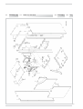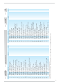
1
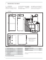
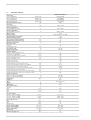
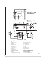
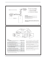
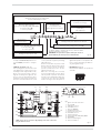
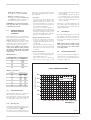
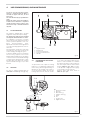
UK
PLEASE LEAVE THIS INSTRUCTION
WITH THE USER
Dewy 30/130
HE FS
Installation and
servicing instructions
SAFE HANDLING
This boiler may require 2 or more operatives to move it into its installation site, remove it from its packaging and during
movement into its installation location. Manoeuvring the boiler may include the use of a sack truck and involve lifting pushing
and pulling.
Caution should be exercised during these operations.
Operatives should be knowledgeable in handling techniques when performing these tasks and the following precautions
should be considered:
– Grip the boiler at the base
– Be physically capable
– Use personal protective equipment as appropriate e.g. gloves, safety footwear.
During all manoeuvres and handling actions, every attempt should be made to ensure the following unless unavoidable
and/or the weight is light.
– Keep back straight
– Avoid twisting at the waist
– Always grip with the palm of the hand
– Keep load as close to the body as possible
– Always use assistance
WARNING
Caution should be exercised when performing any work on this appliance.
Protective gloves and safety glasses are recommended.
– Avoid direct contact with sharp edges.
– Avoid contact with any hot surfaces.
NOTICE
Please be aware that due to the wet testing of the appliance, there may some residual water in the hydraulic circuit.
– Protect any surfaces, carpets or floorings.
– Use a suitable container to catch any water that escape when removing the protective caps from the connections.
All descriptions and illustrations provided in this manual have been carefully prepared but we reserve the right to make changes
and improvements in our products that may affect the accuracy of the information contained in this manual.
The Benchmark Scheme
Sime Ltd is a licensed member of the Benchmark Scheme which aims to improve the standards of installation and
commissioning of domestic heating and hot water systems in the UK and to encourage regular servicing to optimise safety, efficiency and performance.
Benchmark is managed and promoted by the Heating and Hotwater Industry Council.
For more information visit www.centralheating.co.uk
IPX4D
Dewy 30/130 HE FS:
Gas Council number 47-283-05
These appliances comply with the S.E.D.B.U.K. scheme, band “A”
CONTENTS
1
DESCRIPTION OF THE BOILER . . . . . . . . . . . . . . . . . . . . . . . . . . . . . . . . . . . . . . . . . . . . . . . . . . . . . . . . . . . . . . . . pag.
6
2
INSTALLATION . . . . . . . . . . . . . . . . . . . . . . . . . . . . . . . . . . . . . . . . . . . . . . . . . . . . . . . . . . . . . . . . . . . . . . . . . . . . . . pag.
10
3
4
CHARACTERISTICS . . . . . . . . . . . . . . . . . . . . . . . . . . . . . . . . . . . . . . . . . . . . . . . . . . . . . . . . . . . . . . . . . . . . . . . . . . pag.
USE COMMISSIONING, AND MAINTENANCE
(including BENCHMARK/Mains Pressure Hot Water Storage Checklist & Service Record) . . . . . . pag.
19
23
5
EXPLODED VIEWS . . . . . . . . . . . . . . . . . . . . . . . . . . . . . . . . . . . . . . . . . . . . . . . . . . . . . . . . . . . . . . . . . . . . . . . . . . . pag.
32
Important Information
IT IS A STATUTORY REQUIREMENT THAT ALL GAS APPLIANCES ARE INSTALLED BY COMPETENT PERSONS,
IN ACCORDANCE WITH THE GAS SAFETY (INSTALLATION AND USE) REGULATIONS (CURRENT EDITION). The
manufacturer’s instructions must not be taken as overriding any statutory requirements, and failure to comply with these regulations may lead to prosecution.
No modifications to the appliance should be made unless they are fully approved by the manufacturer.
GAS LEAKS: DO NOT OPERATE ANY ELECTRICAL SWITCH, OR USE A NAKED FLAME. TURN OFF THE GAS
SUPPLY AND VENTILATE THE AREA BY OPENING DOORS AND WINDOWS CONTACT THE GAS EMERGENCY
SERVICE ON 0800111999.
Please refer to commissioning instructions for filling in the checklist of this installation guide.
Note: All Gas Safe registered installers carry a ID Card.
You can check your installer is Gas Safe Registered by calling 0800 408 5577
IMPORTANT
When carrying out commissioning of the boiler, you are highly recommended to perform the following checks:
– Make sure that there are no liquids or inflammable materials in the immediate vicinity of the boiler.
– Make sure that the electrical connections have been made correctly and that the earth wire is connected to a
good earthing system.
– Open the gas tap and check the soundness of the connections, including that of the burner.
– Make sure that the boiler is set for operation for the type of gas supplied.
– Check that the flue pipe for the outlet of the products of the combustion is unobstructed and has been properly
installed.
– Make sure that any shutoff valves are open.
– Make sure that the system is charged with water and is thoroughly vented.
– Check that the circulating pump is not locked (CAUTION: Remember to release the pump coupled with the control
panel, if necessary, to protect the electronic control card).
– Purge the system, bleeding off the air present in the gas pipe by operating the pressure relief valve on the gas
valve inlet.
– Check that the syphened drip is fully filled with water. If necessary, fill it via the special opening.
– Ensure that the Benchmark checklist in the use and maintenance section of this manual is completed.
1
DESCRIPTION OF THE BOILER
1.1
INTRODUCTION
“DEWY 30/130 HE FS” boilers are premix
condensation thermal appliances which use
microprocessor technology for function
These appliances can be fired by natural
gas (methane) and propane gas (G31).
The instructions given in this manual are
provided to ensure proper installation and
perfect operation of the appliance.
DIMENSIONS
610
600
65
1.2
control and management. They comply with
the european directives 90/396/CEE,
2004/108/CE,
2006/95/CE,
92/42/CEE and with the european specifications EN 483 - EN 625.
252
76
140
M2
R2
M1
R1
M
R
70
70
315
S1
117
1620
C1
62
U
S3
828
846
712
946
1349
1229
1109
G
349
C
109
E
S2
300
300
E
SUPPLIED WITH THE BOILER:
- Pressure reducing valve
- Single check valve
- Expansion relief valve and
associated tundish
Fig. 1
SERVICE CLEARANCES
CONNECTIONS
R
R1
R2
M2
M1
M
G
E
U
S1/S2
S3
6
Zone 1 system return
Zone 2 system return (optional)
Zone 3 system return (optional)
Zone 3 system delivery (optional)
Zone 2 system delivery (optional)
Zone 1 system delivery
Gas connection
D.H.W. inlet
D.H.W. outlet
C.H. safety relief valve/tank
Condensation outlet ø 25
3/4” (UNI-ISO 228/1)
3/4” (UNI-ISO 228/1)
3/4” (UNI-ISO 228/1)
3/4” (UNI-ISO 228/1)
3/4” (UNI-ISO 228/1)
3/4” (UNI-ISO 228/1)
3/4” (UNI-ISO 228/1)
3/4” (UNI-ISO 228/1)
3/4” (UNI-ISO 228/1)
ABOVE THE APPLIANCE CASING
AT THE R.H.S.
AT THE L.H.S.
IN FRONT OF THE APPLIANCE
300 mm
300 mm
300 mm
700 mm
ACCESS TO THE CONNECTIONS AT THE REAR OF THE BOILER MUST
BE PROVIDED.
1.3
TECHNICAL FEATURES
DEWY 30/130 HE FS
Heat output
Nominal (80-60°C)
Minimum (80-60°C)
Nominal (50-30°C)
Minimum (50-30°C)
Nominal D.H.W. heat output
Heat input
Nominal/Minimum
Efficiency (80-60°C)
Nominal/Minimum output
Efficiency (50-30°C)
Nominal/Minimum output
Water content
Electrical supply
Adsorbed power consumption
Electrical protection grade
C.H. pressure relief valve setting
Maximum C.H. working pressure
Maximum temperature
Expansion vessel
Capacity
Preloading pressure
C.H. setting range
D.H.W. setting range
D.H.W. production
Maximum D.H.W. supply pressure
D.H.W. flow rate (EN 625)
Continuous D.H.W. flow rate ∆t 30°C
D.H.W. operating pressure
Maximum D.H.W. pressure
D.H.W. tank capacity
D.H.W. expansion vessel
D.H.W. expansion vessel charge pressure
D.H.W. tank heating time between 15 and 60°C
Recuperation time between 25 and 55°C
Recuperation time to raise 70% of volume to 60°C
D.H.W. expansion relief valve setting
Combined temperature & pressure relief valve setting
Combined temperature & pressure relief valve setting
Smokes temperature
Maximum/ Minimum (80-60°C)
Maximum/ Minimum (50-30°C)
Smokes flow
Category
Type
Weight
Weight (full)
Main burner nozzles
Quantity
G20
G25
G31
Gas consumption
Nominal / Minimum (G20)
Nominal / Minimum (G25)
Nominal / Minimum (G31)
Gas supply pressure
G20
G25
G31 (Propan)
CO2 % methane (G20)
CO2 % methane (G25)
CO2 % propan (G31)
CO emission
NOx emission (Class 5)
(1) Flow
kW (kcal/h)
kW (kcal/h)
kW (kcal/h)
kW (kcal/h)
kW
29,3 (25.200)
10,4 (9.000)
32,0 (27.600)
11,4 (9.800)
29,3
kW
30,0 / 10,8
%
97,7 / 96,7
%
l
bar
bar
°C
106,8 / 105,8
10,9
230V 50 Hz Fuse et 1.6AT
175
IP X4D
3
2.5
85
l
bar
°C
°C
10
1
20 - 80
10 - 60
bar
l/min
l/min
bar
bar
l
l
bar
min
min
min
bar
bar
°C
10
21,0
14
3.5
6
120
4
3.5
18’ 7”
9’ 40”
14’ 49”
6
7
90
°C
°C
kg/h
70 / 69
48 / 45
49
II2H3P
B23/C13-33-43-53
190
321.1
W
kg
kg
n°
ø mm
ø mm
ø mm
1
6,0
7,7
4,3
m3st/h
m3st/h
kg/h
3,17 / 1,14
3,69 / 1,32
1,22 / 0,44
mbar
mbar
mbar
min/max
min/max
min/max
ppm
ppm
20
25
37
9,2 / 9,3
9,5 / 9,6
10,1 / 10,3
27
35
calculated with a fixed temperature on the hot-water service potentiometer of 60°C for a maximum period of 10 minutes
7
1.4
FUNCTIONAL DIAGRAM
PUMP KIT 2/3 ZONE
CONFIGURATION
KEY
1 Fan
2 Main heat exchanger
3 Main heat exchanger air vent
4 Gas valve
5 Gas rate adjuster
6 C.H. sensor (SM)
7 Flow switch assembly
8 Zone 1 system pump
9 Non return valve
10 Hot water cylinder pump
11 Expansion vessel
12 Drain vent
13 Air relief valve
14 Automatic by-pass
15 D.H.W. Cylinder drain cock
16 Cylinder sensor pocket (SB)
17 Cylinder
18 Sacrificial Anode
19 D.H.W. temperature/pressure relief.
20 Filling loop (optional cod. 8091810)
21
22
23
24
25
26
27
28
29
30
31
32
33
D.H.W. expansion vessel
Water pressure transducer
System pressure relief valve
Condensation trap
Limit stat 85°C
100°C safety stat
System delivery manifold
System return manifold
Tundish
Pressure reducing valve
Single check valve
Expansion relief valve
Tundish expansion relief valve
PUMP KIT 2/3 ZONE CONFIGURATION
(code 8100700/8100710)
34 Zone 2 and 3 system pump
35 Zone 2 and 3 single-acting valve
36 Zone 2 and 3 system bypass
Fig. 2
8
1.5
MAIN COMPONENTS
PUMP KIT 2/3 ZONE CONFIGURATION
(Cod. 8100700/8100710)
FILLING LOOP CONFIGURATION
(Cod. 8091810)
LEGEND
1 Cylinder
2 Cylinder drain cock
3 Cylinder expansion vessel.
4 Tun dish
5 Cylinder temperature/pressure relief
6 Air relief valve
7 Gas valve
8 Zone 1 heating system
pump
9 Gas rate adjuster
10 Zone 1 non return valve
11 Condensation trap
12 Heat exchanger air vent
13 Positive pressure intake
14 Negative pressure intake
15 Ignition transformer
16 Ionisation electrode
17 Main exchanger
18 Ignition electrode
19 Control panel
20
21
22
23
24
25
27
28
31
32
33
34
35
36
37
38
Fan
Heating sensor (SM)
100°C safety thermometer
System pressure
relief valve
Water pressure transducer
Non return valve
Hot water cylinder pump
Flow switch assembly
Drain vent
Drain vent
Zone 2 heat pump
(optional)
Zone 2 single-acting valve
(optional)
Zone 3 single-acting valve
(optional)
Zone 3 heat pump
(optional)
Smoke stat
Filling loop (optional)
Fig. 3
9
2
INSTALLATION
Where no specific instructions are given,
the installation should be in accordance
with the relevant recommendations in the
current editions of the following British
Standards and Codes of Practice: BS
5440-1, BS 5440-2, BS 5449, BS 5482
(propane installations), BS 5546, BS 6700,
BS 6798, BS 6891, Institute of Gas Engineer document IGE/UP-7, BS 7074 (expansion vessel), and to other relevant British
Standards or code of Practice as necessary. It is a Statutory Requirement that
the installation conforms to the appropriate Building Regulations either The Building
Regulations, The Building Regulations (Scotland), Building Regulations (Northern Ireland), the Water Fitting Regulations or
Water Byelaws in Scotland, and the current I.E.E Wiring Regulations. When handling, due consideration should be given to
the appliance weight. If the appliance is not
to be installed immediately it should be stored in a clean dry place.
2.1
BOILER ROOM
The “DEWY 30/130 HE FS” version boilers
can be installed in any domestic environment without any location restrictions ,
other than the load bearing capacity of the
floor where the appliance is to be sited,
(consult section 1.3 for weight), or “Combustion” air requirements. However, suitable
clearances for maintenance and servicing
should be provided, see fig. 1.
2.2
CONNECTING UP SYSTEM
Before connecting the boiler it is recommended that the system is flushed in
accordance with BS7593. When making
the hydraulic connections, make sure that
the dimensions indicated in fig. 1 are
respected. Fit the supplied; pressure reducing valve (30 fig. 2), check valve (31 fig. 2)
and expansion relief valve assembly (32 fig.
2) with its associated tundish (33 fig. 2), in
the D.H.W. supply to the appliance, see fig.
2 and fig. 4 for details. It is important that
no isolating valve is fitted between the
expansion relief valve and the inlet to the
D.H.W. tank. Any additional D.H.W. drain
down cock fitted should be positioned as low
as possible to ensure that at least 80% of
the D.H.W. tank’s capacity can be drained.
If installed in a Hard Water area, then a suitable device should be fitted to treat the
mains supply to the appliance (Contact your
Water Distribution Company for advice on
suitable devices). The pressure relief
discharge pipes must be connected to
ensure safe discharge. The gas connection must be made using seamless steel
pipe (Mannesmann type), galvanized and
with threaded joints provided with
gaskets, excluding three-piece connections, except for initial and end connections. Where the piping has to pass through walls, a suitable insulating sleeve must
10
be provided. When sizing gas piping, from
the meter to the boiler, take into account
both the volume flow rates (consumption)
in m3/h and the relative density of the gas
in question. The sections of the piping
making up the system must be such as to
guarantee a supply of gas sufficient to cover
the maximum demand, limiting pressure
loss between the gas meter and any apparatus being used to not greater than 1.0
mbar for family II gases (natural gas). An
adhesive data plate is stuck inside the front
panel; it contains all the technical data identifying the boiler and the type of gas for
which the boiler is arranged.
the occupants and any tundish, drain valve
and discharge pipe and must be sited away
from any electrical components. The connections to the expansion relief valve and
temperature and pressure relief valve
should not be used for any other purpose.
See fig. 4 for example of the discharge
pipe(s) for the temperature and pressure
relief valve, and expansion relief valve terminations.
NOTE: it is permitted to connect discharge
pipes together provided that the joint pipe is
sized to accommodate the combined flow.
2.2.5
2.2.1
Connection of condensation water trap
To ensure safe disposal of the condensate
produced by the flue gases, reference
should be made to BS6798:2009. The boiler incorporates a condensate trap which
has a seal of 75 mm, therefore no additional trap is required. The condensate should
ideally be discharged internally into an internal waste pipe(washing machine/sink
waste) or a soil pipe to avoid the risk of freezing. External pipe runs should be avoided,
but if it is necessary, the pipework should be
at least 32 mm and protected from the risk
of freezing with a waterproof insulation and
the length kept to a minimum and not
exceeding 3 m termination should be into
an external gully or purpose made
soakaway. We recommend that the condensate drain at the boiler is in 20 mm solvent weld pipe with a socket covering the
connection to the trap. Alternatively a suitable hose can be secured to the trap and terminated as required.
NOTE: All pipework must have a continuous
fall from the boiler and must be resistant to
corrosion by condensate, copper or steel is
NOT suitable. It should be noted that the
connection of a condensate pipe to a drain
may be subject to local building control
requirements.
2.2.2
Filter on the gas pipe
The gas valve is supplied with an inlet filter,
however, this may not be adequate to entrap
all the impurities in the gas or in gas main
pipes. To prevent malfunctioning of the valve
it may be necessary toinstall an adequate filter on the gas pipe.
2.2.3
Filling the Condensate Trap
The condensate trap can be filled, prior to fitting the flue by carefully pouring approximately 1 litre of water into the centre of the
exhaust terminal of the main heat exchanger.
2.2.4
Discharge Pipes and fittings
The position of any tundish must be visible to
Expansion Vessel (C.H. only)
C.H. EXPANSION VESSEL – The integral
expansion vessel is pre-charged to a pressure of 1.0 bar, which should be checked
before the C.H. water system is filled.
This vessel is suitable for correct operation
of system capacities up to 82 litre capacity.
If the actual C.H. system volume is greater,
then an additional vessel must be fitted to
the system.
For systems where the volume is greater,
the additional expansion vessel volume can
be determined by multiplying the volume in
excess of that which can be accommodated by the appliance by the factor 0.901.
BS 7074 gives further details regarding
C.H. expansion vessel sizing.
2.3
CHARACTERISTICS
OF C.H. FEEDWATER
– All recirculatory systems will be subject
to corrosion unless an appropriate
water treatment is applied. This means
that the efficiency of the system will
deteriorate as corrosion sludge accumulates within the system, risking damage to pump and valves, boiler noise
and circulation problems.
– For optimum performance after installation this boiler and its associated central heating system must be flushed in
accordance with the guidelines given in
BS 7593 “Tr eatment of wat er in
domestic hot water central heating systems”.
– Sime Ltd recommend only the use of
FERNOX products for the flushing and
final treatment of the system water.
This is particularly important in hard
water areas. Failure to flush and add
inhibitor to the system may invalidate
the appliance warranty. Artificially softened water must not be used to fill the
heating system.
Failure to flush and add inhibitor to
the system may invalidate the appliance warranty.
– It is important to check the inhibitor
concentration after installation, system
modification and at every service in
accordance with the manufacturer’s
instructions (Test kits are available from
inhibitor stockists).
Fig. 4
2.4.
FILLING AND COMMISSIONING
2.4.1
D.H.W. circuit
Before filling the D.H.W. system, ensure
appliance selector knob is in the “Off” position, then open the hot water tap nearest
the appliance.
Open the D.H.W. supply isolating valve to
the appliance, once water starts to flow
from the tap close it, and then open and
close each hot water tap in turn to ensure
t hat all t he air is r emoved fr om t he
pipework. Open the hot water tap furthest
away from the appliance and let water flow
for about 10 minutes, or for sufficient time
to flush out the system. Check for leaks.
2.4.2
arrangement. Ensure both the D.H.W. and
C.H. temperature controls are set to minimum, and that there is no room thermostat demand. Turn on the electrical supply
to the appliance (see Section 2.8), and turn
the selector knob to the summer position.
To use the internal filling loop, ensure that
the flexible hose is attached to both valves,
then open the C.H. isolating valve and then
open the D.H.W. double check isolating
valve, (See fig. 2).
Once the green “1 bar” led lights up close
both isolating valvesensure that all the
radiators are vented, continue opening the
filling loop to maintain the 1 bar pressure.
When all the radiators are vented ensure
the pressure is at 1 bar. then disconnect
the flexible hose from the D.H.W. double
check isolating valve. Check for leaks and
free rotation of the circulating pumps.
sate trap can be filled see 2.2.3. The coaxial
suction and discharge pipes are supplied in
a special kit (that can be purchased separately) along with assembly instructions. The
diagrams of fig. 5 illustrate some examples
of different types of discharge options
allowed and the maximum lengths that can
be reached. It is essential that a flue gas
analysis test point is made available directly
above the boiler.
2.5.1
Coaxial duct accessories
The maximum flue length using 60/100
ducts and accessories must not exceed 2.8
metres.
2.5.2
Positioning the outlet terminals
C.H. circuit
Once the D.H.W. circuit is commissioned
the C.H. circuit can be filled via the internal
filling loop (if fitted), or via any external
2.5
COAXIAL DUCT ø 60/100
Prior to fitting the flue system the conden-
The outlet terminals for forced-draught
appliances may be located in the external
perimeter walls of the building.
To provide some indications of possible solu11
NOTE: Place the duct horizontally.
KEY
1a-b
2a
2b
3
4a
4b
Coaxial duct kit code 8096250
Extension L. 1000 code 8096150
Extension L. 500 code 8096151
Vertical extension L. 140 with
take-off point code 8086950
90° additional bend code 8095850
45° additional bend code 8095950
IMPORTANT:
Each additional 90° curve installed reduces the
available length by 0.90 metres.
Each additional 45° curve installed reduces the
available length by 0.45 metres.
NOTE: Before installing accessories, lubricate the internal
part of gaskets with silicon-based products. Avoid using
oils and greases.
Fig. 5
TABLE 1
Terminal position
Minimum spacing
A
Directly below an openable window, air vent
or any other ventilation opening
300 mm 12 in
B
Below guttering, drain pipes or soil pipes
75 mm
3 in
C/D Below eaves, balconies or carport roof (*)
200 mm
8 in
E
From vertical drain pipes or soil pipes
75 mm
3 in
F
From internal or external corners
300 mm 12 in
G
Above adjacent ground, roof or balcony level
300 mm 12 in
H
From a boundary or surface facing the boiler
600 mm 24 in
I
From a terminal facing the terminal
1,200 mm 48 in
J
From an opening in the carport
(eg door, window into dwelling)
1,200 mm 48 in
K
Vertically from a terminal on the same wall
1,500 mm 60 in
L
Horizontally from a terminal on the same wall
300 mm 12 in
M Horizontally from a vertical terminal to a wall
300 mm 12 in
N Horizontally from an openable window or other opening 300 mm 12 in
P
Above an openable window or other opening
300 mm 12 in
Q
From an adjacent vertical terminal
600 mm 24 in
– If the terminal discharges into a pathway or passageway
check that combustion products will not cause nuisance
and that the terminal will not obstruct the passageway.
– Where the lowest part of the terminal is fitted less than 2
m (78 in) above ground, above a balcony or above a flat roof
to which people have access, the terminal MUST be protected by a purpose designed guard.
– Where the terminal is fitted within 850 mm (34 in) of a
plastic or painted gutter, or 450 mm (18 in) of painted
eaves, an aluminium shield at least 1,500 mm (59 in) long
must be fitted to the underside of the painted surface.
– The air inlet/outlet flue duct MUST NOT be closer than 25
mm (1 in) to combustible material.
– In certain weather conditions the terminal may emit a
plume of steam. This is normal but positions where this
would cause a nuisance should be avoided.
(*) Note : this can be reduced to 25 mm, but it would be necessary to protect the
surfaces from the effects of condensate.
Fig. 5/a
12
tions, Table 1 gives the minimum distances
to be observed, with reference to the type
of building shown in fig. 5/a.
SEPARATE PIPES ø 80
A special kit may be used to separate the
flue gas outlet from the air intake. The
intake may be installed to the right or left of
the flue gas outlet. It is essential that a flue
gas analysis test point is made available
directly above the boiler. Refer to fig. 8 for
2.6.1
Separate pipe accessories
Kit code 8089911 is supplied for this purpose (fig. 9).
ELECTRICAL CONNECTION
Wiring external to the appliance must be in
accordance with the current I.E.E Wiring
regulations (BS 7671) for electrical installation and any local regulations, which apply.
Connection to the mains supply must facilitate complete electrical isolation of the
appliance. A 3A fused double pole switch
having a 3 mm contact separation in both
poles and serving only the appliance (and its
external controls) may be used.
The boiler is supplied with an electric cable.
105
Z
P
Ø 80
L
2.8
Ø 80
K
155
2.6
positioning. The maximum overall length of
the intake and exhaust ducts depends on
the head losses of the single fittings
installed (excluding the doublers) and
must not be greater than 15,5 mm H2O.
For head losses in the fittings, refer to Table
2.
CA
CS
KEY
CA Inlet
CS Outlet
TABLE 2
Accessories ø 80
Inlet
K
L
P
Z
mm
mm
mm
mm
90° elbow MF
45° elbow MF
Extension L. 1000 (horizontal)
Extension L. 1000 (vertical)
Outlet terminal
Inlet terminal
Doubler fitting
Roof outlet terminal L. 1381
DEWY 30/130 HE FS
348
263
230
315
3
2
4
5
3
0.30
0.20
0.20
0.30
–
0.10
0.30
–
Head loss (mm H2O)
Outlet Roof outlet
0.50
0.40
0.40
0.30
0.40
–
–
–
–
–
–
–
–
–
–
0.60
Fig. 8
1
KEY
1 Blind flange
2 Flue gas duct flange
3 Fixing screw
4 Gasket ø 125/95
5 Intake duct collar
Fig. 9
13
Should this require replacement, it must be
purchased exclusively from SIME.
The electric power supply to the boiler must
be 230V - 50Hz single-phase.
Respect the L and N polarities and the
earth connection.
on the electrical panel.
NOTE: Device must be connected to an
efficient earthing system. SIME declines
all responsibility for injury or damage to
persons, animals or things, resulting from
the failure to provide for property
earthing of the appliance. Always turn off
the power supply before doing any work
To gain access to the electronic board connector (3), remove the control panel cover
and connect the room stat to the terminals
TA (5-6) after having removed the jumper.
The thermostat or timer-thermostat, must
be class II as specified by standard EN
60730.1 (clean contact).
2.8.1
Room thermostat
connection
(fig. 12 pos. A)
KEY
1 Control panel
2 “Logica Remote Control” socket
3 Conector (J2)
TA Room stat (not supplied)
CR Logica Remote Control (optional)
SE External temperature sensor (optional)
SB D.H.W. sensor
WARNING: Applying mains voltage to the
terminals of conector (3) will irreparably
damage the control board. Make sure
that any connections to be made are not
carrying mains voltage.
2.8.2
“Logica Remote Control”
connection (fig. 12 pos. B)
The electrical plant must comply with local
standards and all cables must comply with
low voltage safety requirements of EN
60730. For lengths up to 25 m, use cables
TA
SB
A
3
2
CR
SB
B
1
CR
SE
SB
C
Fig. 12
14
of section 0.25 mm2, for longer lengths up
to 50 m use cables of section 0.5 mm2.
Connect as shown (2). To gain access to
connector (3) remove the control panel
cover and connect the climate regulator to
terminals CR (7-8).
connected to terminals 1-2-3-4 of the
"Logica Remote Control".
WARNING: External voltage must not be
The cables must comply with low safety vol-
2.8.4
2.8.3
tage requirements of EN 60730. For lengths
up to 25 m, use cables of section 0.25 mm2,
for longer lengths up to 50 m use cables of
section 0.5 mm2.
To gain access to boiler connector (3) remove the control panel cover and connect the
external temperature sensor to terminals
SE (9-10).
External temperature sensor
connection (fig. 12 pos. C)
Wiring diagram
J7
J5
J6
J4
J8
J3
J2
J1
J2
J9
J10
KEY
EV1
EV2
EA
ER
TS
V
TPA
PI
SE
TA
SM
TL
TRA
TR
FL
SB
CR
SV
OP
Gas valve coil
Gas valve coil
Ignition electrode
Ionisation electrode
100°C safety stat
Fan
Water pressure transducer
Pump
External sensor (optional)
Room thermostat
C.H. sensor
Limit stat
Ignition transformer
Transformer 230 - 24V
Flow switch
D.H.W. sensor
Logica Remote Control (optional)
Fan board
Time programmer
TF
PB
PR
J1
Smoke stat
Hot water cylinder pump
Recirculation pump (optional)
Note: Room thermostats (TA), with voltage free(clean
contacts) are connected to terminals 5-6.
CONNECTOR SPARE PART CODES (Main PCB):
J1 code 6316215
J2 code 6278613
J3 code 6299961
J4 code 6293564
J5 code 6299921
J6 code 6278699
J7 code 6278636
J8 code 6098305
CONNECTOR SPARE PART CODES (Fan driver PCB):
J1 code 6260996
J2 code 6278661
Fig. 13
15
2.9
TIME PROGRAMMER
The boiler is supplied with a programmer
clock (fig. 14).
For instructions on how to use this clock,
see the user's manual.
Fig. 14
2.10
LOGICA REMOTE CONTROL
The boilers functions can be remotely controlled with the use of a optional programmer 8092204. Climatic influence can also
be achieved with the further additional
external sensor 8094100.
Characteristics:
– Ergonomic control unit divided according
to function (control levels)).
– Clear division of basic functions:
• operating regime, correction of set
value and presence button are directly
accessible;
• Dif ferent real current values are
accessible through the "info" button;
• other functions can be programmed
after the cover has been opened;
• special service level with protected
access;
– Each setting or modification is displayed
and confirmed.
– Tome setting (special line for changing
BST/CET).
– Heating programme with max. 3 heating
periods per day, individually selectable.
– Copy function for easy transfer of heating programme to the next or previous day.
– Holiday programme: the programme is
interrupted for the holiday period and automatically restarted on returning home.
16
– Option to return the heating program to
default values.
– Programming lock (child safety).
Functions:
– Delivery temperature control guided by
the atmospheric conditions, taking into
account the dynamics of the building.
– Delivery temperature control guided by
atmospheric conditions with influence of
ambient temperature.
– Ambient temperature control only.
– Adjustable influence of ambient temperature shift .
– Switch-on and switch-off optimisation.
– Rapid lowering.
– ECO functions (daily heating limiter, automatic summer/winter switch-over).
– Controllable maximum delivery temperature limit (specifically for floor plants).
– Limitation of increase in pre-set delivery
temperature.
– Anti-freeze protection for buildings.
– Hourly programming of the tank unit
temperature on two levels: comfort and
reduced.
– Domestic hot water control with nominal
value requirement and enable.
– Connection to room sensor or switching
of operating regime through the telephone system with external contact or
through a window contact.
– Anti-bacterial.
2.10.1 Installation
The unit must be installed in the main living
room. For installation, follow the assembly
instructions inserted in the package.
At this point, with the selector knob on ( ),
the installer can adjust the basic parameters settings according to the individual
needs (point 2.8.2).
If there is a thermostatic radiator valve
fitted, this must be set to maximum.
2.10.2 Installation settings
The settings for the basic operating parameters for individual needs are reported in
the instruction leaflet supplied with the
"Logica Remote Control" and in the section
reserved for the user in this manual.
For further adjustments which can be carried out by the installer, the "Logica Remote
Control" offers a level of service and parameterising which can only be accessed
through a special combination of buttons.
To activate this level of service or parameterising press buttons
and
least 5
seconds.
This will activate the parameterising level.
Then use the same arrow buttons to select
the individual input lines and adjust the
values with
or
.
HEATING CIRCUIT SETTINGS
Antifreeze protection
"Pre-set ambient
temperature value"
51
Heating takes place up to this pre-set value if the plant is activated in standby
(e.g. holidays).
In this way, the building antifreeze function is active, preventing an excessive
lowering of the ambient.
Summer/Winter switch-over
temperature
52
This parameter regulates the temperature of the automatic summer/winter switch-over.
Type of control:
0 = with ambient influence
1 = without ambient influence
53
This parameter de-activates the ambient influence and as a result all the
optimisations and adaptations.
If a valid external temperature is not transmitted , the controller switches to
the pure ambient control guide variable.
Influence of ambient temperature
54
If the ambient controller is used only as a remote control (placed in the reference room and without an external sensor connected), the value must be
set at 0 (zero).
If the change in ambient temperature from the pre-set value remains high
during the entire day, the influence must be increased. If the ambient temperature is around the pre-set value (control oscillation), the influence must
be reduced.
Note: If the ambient temperature influence constant is set at 0, the adaptation of the heating curve is deactivated. In this case, parameter 57 will
have no effect at all.
Maximum limit of delivery
temperature
55
The delivery temperature is limited to the maximum set value.
Variation of the maximum speed of the
delivery temperature
56
The increase per minute of the prescribed delivery temperature value sent
in °C is limited to the imposed value.
Activation of adaptation
57
With the activation of the adaptation, the pre-set value transmitted to the
boiler regulator is adapted to the effective heat need.
The adaptation functions with both the atmospheric guide with ambient
influence and with pure ambient control.
If the "Logica Remote Control" is set as a remote control only, the adaptation
must be is deactivated.
Optimisation of
switch-on time
58
If the switch-on time optimisation is active, the "Logica Remote Control" modifies the heating gradient until it finds the optimum heating point
0 = off
1 = on
Heating gradient
59
The "Logica Remote Control" selects the switch-on time such that the set
value has more or less been reached at the start of the usage time.
The more severe the night-time cooling, the earlier the heating time starts.
Example: Current ambient temperature
Nominal ambient temperature
Heating gradient
Presetting of switch-on time:
1.5 K x 30 min/K =
18.5°C
20°C
30 min/K
45 minutes
00 means that the switch-o time has not been pre-set (function disabled).
Presetting switch-off
time (00 = off)
60
If the switch-off time optimisation is active (value > 0), the "Logica Remote
Control" modifies the pre-set time until it finds the optimum switch-off time..
17
DOMESTIC HOT WATER SETTINGS
Reduced domestic hot
water pre-set value
61
The reduced pre-set value of the temperature of the domestic hot water allow
the required water temperature to be obtained outside the programmed
usage times (daily programme 8).
Domestic hot water load
62
0 = 24 hours/ day - Hot water is always available at the temperature set
with user parameter n°3.
1 = standard - Hot water according to the daily heating programme.
In the comfort areas of heating the temperature of the boiler unit is regulated to the value set with user parameter n° 3.
In the reduced areas of heating the temperature of the boiler unit is
regulated to the value set with parameter n° 61 of the service level.
2 = service disconnected
3 = second daily programme (8) - Every day of the week the temperature of
the hot water is set according to programme 8. In this case there is a
single programming for all the days of the week and three time zones are
available. In the time spans set the temperature of the boiler unit is regulated according to that set in parameter n°3. In the remaining hours the
boiler unit is controlled to the temperature set with parameter n° 61 the
of service level.
63
This block (1) can be activated to display all the parameters without
modifying them. Pressing buttons
or
displays “OFF”.
SERVICE VALUES
Final user level 2
programming block
WARNING:
The activation block can be deactivated temporarily by pressing buttons
and
simultaneously; a confirmation sign appears on the display.
At this point press simultaneously the buttons
and
for at least 5
seconds.
To permanently remove the activation block, set parameter 63 on 0.
Input function terminal 3-4
64
The freely programmable input (terminals 3-4) allows three different functions
to be activated. The parameter has the following significance:
1 = If an external sensor is connected, the display will show the temperature
of the external sensor ( _ _ = no sensor connected, function disabled).
2 = With an external contact, it is possible to switch-over to "reduced preset value of the ambient temperature".
3 = With an external contact, it is possible to switch-over to "reduced preset value of the antifreeze ambient temperature" (short circuit 0 0 0 or
interruption _ _ _ ). The display shows the current status of the external
contact.
Operating mode of external contact
65
If the entrance (terminals 3 and 4 of the base) is connected to a zero potential
external contact (parameter 64 = 2 or 3), the operating mode of the contact
can be determined (remote telephone switch or window contact). The operating
mode specifies the status of the contact in which the required function is active.
Display:
External and ambient
sensor influence
66
Operating mode closed (short circuit)
Operating mode open (interruption)
000
___
Determines the mix ratio between the internal and external ambient sensor
when parameter 64 = 1.
0%
= internal sensor only active (0% external - 100% internal)
50 % = mean value of external + internal sensor
100 % = external sensor only active
The set mix is used for ambient control and display.
If the external sensor is short circuited or interrupted, the operation continues with the internal sensor.
Anti-bacterial function
(with storage capacity boiler unit)
18
69
This function allows the hot water to be brought to a high temperature once
a week in order to eliminate eventual pathogenic agents.
It is active every Monday for a maximum duration of 2.5 hours at a delivery
temperature of 65°C.
0 = not active
1 = active
2.10.3 Gradient of the characteristic
heating curve
The gradient of the characteristic heating
curve is imposed on the current value “15”
of Logica. Increasing the gradient as shown
in the drawing of fig. 15, the delivery temperature increases in correspondence to the
outside temperature.
2.11
EXTERNAL TEMPERATURE
SENSOR
The "Logica Remote Control" can be connected to an external temperature sensor
available a an optional extra (code
8094100). This configuration ensures and
maintains the required temperature constant in the room. The ambient temperature is, in fact, indicted and evaluated as
the calculated mean of the value measured inside and outside the dwelling.
For installation, follow the assembly instructions inserted in the package.
Example: Choosing a gradient of 15 with an outside temperature
of –10°C we shall have a delivery temperature of 60°C.
Fig. 15
3
CHARACTERISTICS
3.1
ELECTRONIC BOARD
The electronic boards are manufactured in
compliance with the EEC 73/23 low-voltage
directives.
They are supplied with 230V and, through a
built-in transformer, send a voltage of 24V
to the following components: gas valve,
safety stat, C.H. and D.H.W. sensor, external
temperature sensor (optional), modulator,
micro divertor valve, flow switch safety
valve, water pressure transducer, room
stat or “Logica Remote Control”.
An automatic and continuous modulation
system enables the boiler to adjust the heat
output to the various system requirements
or the User’s needs.
The electronic components are guaranteed
against a temperature range of 0 to
+60°C.
3.1.1
Fault finding
– “POT. RISC.” trimmer (10 fig. 17)
Sets the maximum heating power value.
To increase the value turn the trimmer
clockwise; to reduce the value turn the
trimmer anticlockwise.
ignition (STEP), of the gas valve.
According to the type of gas for which
the boiler is equipped, the trimmer must
be regulated so as to obtain a pressure
of approx. 3 mbar at the burner for
methane gas and 7 mbar for propane
gas (G31).
To increase pressure, turn the trimmer
clockwise; to reduce pressure, turn the
trimmer counterclockwise.
The slow ignition pressure level can be
set during the first 3 seconds following
burner ignition.
After setting the pressure level upon
ignition (STEP) according to the type of
gas, check that the pressure for heating is still at the value previously set.
– “POT. ACC.” trimmer (6 fig. 17)
Trimmer to vary the pressure level upon
– “MET-GPL” connector (7 fig. 17)
With the connector linked-off, the boiler
The indicator leds signalling irregular
and/or incorrect operation of the equipment are indicated in fig. 16.
3.1.2
Devices
The electronic board is equipped with the
following devices:
19
Flashing red led, fan fault.
30 minutes after the fan has switched off,
the board will attempt a restart
Flashing red led, water
pressure is too low (*)
Flashing red led,
communication fault
with “Logica Remote Control”
Red led on, ignition blocked:
rotate selector CR/OFF/SUM/WIN/RESET
to release position ( )
to restore operation
Green led off if
power is cut-off
Flashing red led,
plant safety
valve tripped (*)
Flashing red led, flame detection circuit fault
Flashing red led, safety/smoke stat tripped.
Rotate selector CR/OFF/SUM/WIN/RESET
to release position ( )
to restore operation
Flashing red led, heating sensor fault (SM)
(*) When all 0.5 to 2.5 bar leds are off, check the water
pressure transducer connection.
WARNING: the operation of plants with open vessels is
guaranteed only for static pressures above 0.7 bar.
Flashing red led, flowmeter fault
is set-up for NATURAL GAS; with the connector linked-on, the boiler is ready for
LPG.
occur in particular in systems presenting
high head losses.
At each restart after the period of slow
ignition, the boiler will set itself for about
1 minute at the minimum modulation
pressure, and will then move to the heating pressure value set.
When the connecting link is inserted,
both the programmed technical pause
and the period of operation at minimum
pressure in the startup phase will be cancelled. In this case, the times elapsing
between turning off and subsequent re-
– “ANN. RIT.” connector (5 fig. 17)
In the heating phase, the electronic board
is programmed to include a burner technical delay interval of approx. 90 seconds,
which occurs both at system cold starting and at subsequent re-ignitions. The
aim is to overcome the problem of repeated ignitions and turning off with very
short time intervals between. This could
11
9
Fig. 16
ignition will depend on a temperature difference of 5°C detected by the SM sensor (heating flow sensor).
– DIP SWITCH (13 fig. 17)
Check that the switches are positioned
as shown.
10
1
6
3
7
12
5
14
15
NOTE: To gain access to trimmers (6) and (10), unscrew the central heating potentiometer knob
8
6
13
10
KEY
1 Ignition electrode earth faston
3 Fuse (1,6 AT)
5 “ANN. RIT.” connector
6 “POT. ACC.” trimmer
7 Conector “MET-GPL”
8 D.H.W. potentiometer
9 Ionisation electrode faston
10 “POT. RISC.” trimmer
11 C.H. potentiometer
12 Selector CR/OFF/SUM/WIN/RESET
13 DIP SWITCH
14 Connector “Modureg Sel.”
15 Connector “Albatros”
Fig. 17
20
– “Modureg Sel.” connector (14 fig. 17)
The bridge must always be connected.
– “Albatros” connector (15 fig. 17)
The bridge must always be disconnected.
It is connected only when multiple boilers
are installed in a sequence/cascade.
ATTENTION: It is essential that the operations described above be carried out by
authorized technical staff.
3.2
TEMPERATURE SENSOR
AND WATER PRESSURE
TRANSDUCER
Boiler frost protection is achieved via the
NTC heating sensor that activates when
the water temperature reaches 6°C.
Tables 3 - 3/a show the resistance values
(Ω) that are obtained on the sensor as the
temperature varies and the transducer
values obtained as the pressure varies.
When sensor (SM) is int errupt ed,
neither of the boiler's heating services
will function. With D.H.W. sensor (SB)
interrupted, the boiler will only work in
heating mode.
TABLE 3 (Sensors)
Temperature (°C)
Resistance (Ω)
20
30
40
50
60
70
80
12.090
8.313
5.828
4.161
3.021
2.229
1.669
failures to occur, with consequent activation of signal indicating that the control box
has “locked out”.
– Gas failure
The control box runs through the cycle
normally sending electric power to the
ignition electrode. The electrode continues spark discharge for a maximum of
10 sec.If the burner does not light, the
lock-out indicator will light up.
This may occur upon first ignition or
after long periods of boiler lay-off when
there is air in the pipes. It may be caused
by the gas cock being closed or by one of
the valve coils having a break in the winding, so that the valve cannot open.
– Ignition electrode fails to spark
In the boiler, only the gas to the burner
is seen to open. After 10 sec. the warning light indicating equipment “lockout” lights up.
This may be due to a break in the wire of
the electrode or to the wire not properly
fastened to the electric terminal of the
control box;
– No detection of flame
The continuous spark discharge of the
electrode is noted starting from ignition
even though the burner is lit.
Af t er 10 seconds have elapsed, the
sparks cease, the burner goes out, and
the warning light indicating equipment
“lock-out” lights up.
There could have a break in the wire of
the sensing electrode or the electrode
itself is touching earth: the electrode is
worn out and needs replacing. The control box is defective.
When there is a sudden voltage failure, the
burner shuts down immediately; when the
power supply returns, the boiler will start
up again automatically.
3.4
FLOW SWITCH
A flow switch (28 fig. 3) intervenes, blocking
the operation of the burner if the boiler is
without water due to the formation of an air
lock in the heat exchanger or if the pump is
not working.
NOTE: the flow switch assembly is replacede, make sure that the arrow stamped
on the valve points in the same direction
as the flow of water.
3.5
SYSTEM AVAILABLE HEAD
For boilers with the standard fittings, the
residual head for the heating system on
the basis of rate of flow is represented in
the diagram in figure 18.
1 HIGH TEMPERATURE ZONE
0
0,5
1
1,5
2
2,5
3
3,5
3.3
Resistance (Ω)
min
max
297
260
222
195
167
137
108
90
320
269
228
200
173
143
113
94
ELECTRONIC IGNITION
Ignition and flame detection is controlled by
two electrodes located on the burner.
These guarantee maximum safety with
intervention times, for accidental switching
off or gas failure, of within one second.
3.3.1
Operating cycle
Rotate the selector knob to summer or winter, and verify that green led ( ) lights up to
confirm the presence of voltage.
The burner must be ignited within 10
seconds. However, it is possible for ignition
600
500
Dewy
Pressure
(bar)
PREVALENZA
RESIDUA
(mbar)
RESIDUAL
HEAD (mbar)
TABLE 3/a (Transducer)
vers. 30/80
vers. 30/130
400
300
200
100
0
200 400 600 800 1000 1200 1400 1600
FLOW RATE (l/h)
(l/h)
PORTATA
Fig. 18
21
3.5.1
Head with total rate of flow
to other zones
In “DEWY 30/130 HE FS” versions using
the second and third zone kit, determine
the head available to the zones as shown in
the following example:
Rate of flow calculated for zone 1 = 350 l/h
Rate of flow calculated for zone 2 = 400 l/h
Rate of flow calculated for zone 3 = 400 l/h
To obtain head available to zone 1, add the
total rate of flow to the other zones (in this
case zones 2 and 3): 400 l/h + 400 l/h =
800 l/h.
As shown in the graph (fig. 18/a) at the
800 l/h curve, head at 350 l/h for zone 1
= 180 mbar.
Zone 3 = 350 l/h + 400 l/h = 750 l/h.
As shown in the graph at the 800 l/y
curve (curve E), head at 400 l/h = 160
mbar.
3.6
The same procedure may be applied to
other zones to obtain:
Zone 2 = 350 l/h + 400 l/h = 750 l/h.
As shown in the graph at the 800 l/h
curve, head at 400 l/h = 160 mbar.
SMOKE
STAT
To ensure an effective protection of the flue
from becoming damaged from excessive
heat, the boiler is supplied with a standard
smoke thermostat (37 Fig. 3).
PREVALENZA
RESIDUA
(mbar)
RESIDUAL HEAD
(mbar)
500
A= 0 l/h
B= 200 l/h
C= 400 l/h
400
D= 600 l/h
E= 800 l/h
DEWY 30/130
3 HIGH TEMPERATURE ZONES
300
200
100
E D C B
0
200
400
600
A
800 1000 1200 1400 1600
FLOW RATE(l/h)
(l/h)
PORTATA
Fig. 18/a
22
4
USE COMMISSIONING, AND MAINTENANCE
To ensure correct operation and efficiency it is important that the boiler is
serviced at regular intervals, at least
once a year.
This must be done only by a qualified technician.
During the routine service the condensate drain can be checked. It is important
should the boiler not be used for some
time that the trap is checked and filled if
required.
4.1
2
D.H.W. PRODUCTION
The cylinder is equipped with a sacrificial
magnesium anode, and inspection flange.
The magnesium anode must be checked
annually and substituted when it is worn.
It is advisable to incorporate a isolation
valve in the domestic supply to the boiler. It
must be positioned upstream of the combined
pressure/backflow
valves.
Adjustment of the flow rate through the boiler can be achieved by adjustment of the isolation valve.
The temperature and pressure relief valve
and expansion relief valves should not be
used for venting or draining the system.
To drain the D.H.W. circuit, turn off the gas
and electricity supplies and close the
D.H.W. supply isolating valve to the appliance. Connect a hose to the D.H.W. discharge
cock (See item 2, fig 3) and feed to a suitable drain. Open a hot water tap, and then
open the D.H.W. discharge cock, to drain
the tank.
4.2
5
1
4 3
KEY
1 Regulation intake
2 EV1-EV2 coils
3 Pressure inlet upstream
4 Pressure inlet downstream
5 OFF-SET
Fig. 20
4.3
ADJUSTMENT OF HEAT OUTPUT
FOR HEATING
To adjust boiler heat output for heating
purposes, i.e., modifying the setting made
at the factory which is approximately 17
kW. Remove the heating control knob to
access the trimmer "B". To increase the
heating output, turn the trimmer clockwi-
GAS VALVE
The boiler, is equipped standard with the
HONEYWELL VK 8115M gas valve (fig. 20).
se; to reduce the heating output, turn the
trimmer counterclockwise. To establish
the output of the boiler conduct a gas rate
test and compare with the values shown
in fig. 21 Tables 4 - 4/a - 4/b; or measure “air ∆p” with a digital pressure gauge
connected up as shown in fig. 21.
Compare values with those shown in
Tables 4 - 4/a - 4/b.
7 6
5
KEY
1 Gas pressure intake
2 Gas valve
3 Mixer intake (–)
4 Ventilator intake (+)
5 Nozzle
6 Fan
7 Air/gas mixer
9 Digital manometer
4
3
9
1
2
Fig. 21
23
Diagram illustrating heat output in relation to “air ∆p”
4.3.1
G31
35
HeatPotenza
outout (kW)
termica kW
HeatPotenza
outout (kW)
termica kW
G20
30
25
C
0°
0-6
C
0°
20
8
-3
50
35
30
25
C
0°
20
15
15
10
10
5
C
0°
-6
80
-3
50
5
0
10
20
30
40
50
60
0
70
10
20
30
40
Air∆p
∆paria
mmmm
H2OH2O
60
70
TABLE 4/b - G31
TABLE 4/a - G20
Variable heat output
(80-60°C) (50-30°C)
kW
kW
29,3
32,0
22,9
25,0
16,1
17,6
10,4
11,4
50
∆p∆p
dearia
airemm
mmHH2O
2O
Air ∆p*
Gas consum.**
(80-60°C) (50-30°C)
G20
mm H2O mm H2O
m3/h st
63,8
66,4
3,17
45,0
45,0
2,48
25,0
25,0
1,75
8,4
9,2
1,14
Variable heat output
(80-60°C) (50-30°C)
kW
kW
29,3
32,0
21,8
23,4
15,4
16,6
10,4
11,4
Air ∆p*
Gas consum.**
(80-60°C) (50-30°C)
G31
mm H2O mm H2O
kg/h
68,4
70,4
1,52
45,0
45,0
1,19
25,0
25,0
0,84
9,2
9,5
0,55
* Air ∆p is measured during boiler operation using a differential pressure gauge connected to the ventilator intake.
** The gas consumptions refer to the calorific value at standard conditions at 15°C - 1013 mbar.
Fig. 22
COMMISSIONING
The gas valve is factory set and should
require no adjustment.
PLEASE NOTE: The combustion for this
appliance has been checked, adjusted and
preset at the factory for operation on the
gas type specified on the appliance data
plate. However it is advisable to check for
correct combustion having first checked:
– That the boiler has been installed in
accordance with these instructions.
– The integrity of the flue system and the
flue seals
– The integrity of the boiler combustion circuit and the relevant seals.
Proceed to put the boiler into operation as
follows, after installation a gas purge and
tightness/drop test have been made.
Ensure that the pump has been manually
rotated. Switch the boiler to the SUMMER
position. Open the gas cock, Ensure that any
timers or room thermostats are in the on
position.
The boiler will attempt to light.
4.5
CHECK THE OPERATIONAL
(WORKING) GAS INLET PRESSURE
Set up the boiler to operate at maximum
24
rate condition (chimney sweep) as
described in 4.6.2.
With the boiler operating in the maximum
rate condition, check that the operational
(working) gas pressure at the inlet test
point (see fig. 20 item 3), complies with the
requirements of 1.3.
Ensure that this inlet pressure can be maintained with all other appliances in the property working.
4.5.1
which covers the use of electronic
portable combustion gas analysers in
accordance with BS7967, parts 1 to 4.
Connect the flue gas analyser to the flue
gas sampling point as shown in fig 23 and
check the combustion following the
sequence described in 4.4.
Combustion Check
Competence to carry out the check of the
combustion performance.
PLEASE NOTE: BS 6798: 2009 Specification
for installation and maintenance of gas-fired
boilers of rated input not exceeding 70 kw
net advises that:
– The person carrying out a combustion
measurement should have been
assessed as competent in the use of a
flue gas analyser and the interpretation
of the results;
– The flue gas analyser should be one
meeting the requirements of BS7927 or
BS-EN50379-3 and be calibrated in
accordance with the analyser manufacturers requirements, and competence
can be demonstrated by satisfactory
completion of the CPA1 ACS assessment
Fig. 23
CO / CO2 RATIO
100
CO2 %
4.4
NG 9%
LPG 10%
0,0011
0,0010
CO ppm
400
0,0044
0,0040
4.6
BOILER CALIBRATION
The boiler must always be calibrated while set on heating.
“∆p air” ADJUSTMENT
“∆p air-gas” ADJUSTMENT
To measure “∆p air” simply connect a differential pressure
gauge with a decimal or Pascal
scale to the positive and negative tap, observing the symbols
(Drawing 1).
To measure “∆p air-gas”, simply
connect the positive tap of the
differential pressure gauge to
the gas tap and the negative
tap to the corresponding tap on
the boiler (Drawing 4)
Drawing 1
Sequence of operations:
1) Turn the heating power control trimmer clockwise as
far as it will go (B – Drawing
2) with the fan at its top
speed.
2) Attempt to achieve the “∆p
air” values given in the table
by adjusting the MAX trimmer on the fan board
(Drawing 3):
∆p air max.
Dewy
25
Natural gas (G20) 49,5
Propane (G31) 49,5
B
Drawing 2
Always adjust gas pressure
with the fan at its top speed.
Drawing 4
Sequence of operations:
1) Turn the heating power control trimmer anti-clockwise
as far as it will go (B –
Drawing 5) with the fan at
its top speed.
B
2) Open the gas capacity step
(1 – Drawing 6) all the way
so that the notch is in a horizontal position.
30
63,8
68,4
1
3) Turn the heating power control trimmer anti-clockwise
as far as it will go (B –
Drawing 2) with the fan at
its top speed.
4) Attempt to achieve the “∆p
air” values shown in the
table using the “MIN” trimmer on the fan board
(Drawing 3):
MIN. MAX
“∆p air”
adjustment
2
Drawing 6
3) Adjust the gas valve OFFSET regulation (2 – Drawing 6), aiming
to achieve the “∆p air- gas” shown in the table:
Capacity step open
Dewy
Natural gas (G20)
Propane (G31)
Drawing 3
∆p air min.
25
7,3
8,1
30
7,0
10,1
4) Using the capacity step (1 – Drawing 6), attempt to achieve the
“∆p air-gas” shown in the table:
Capacity step regulated
Dewy
25
Natural gas (G20) 7,1
Propane (G31)
Drawing 5
7,1
30
Dewy
Natural gas (G20)
Propane (G31)
8,4
9,2
25
5,3
4,4
30
6,3
9,0
Upon completion of the calibration procedure, check CO2 values using a combustion analyser. If a difference which is more than 0.2 above
or below the values indicated in the table is found, it will be necessary to correct it:
“MIN” output
“MAX” output
“Dewy 25”
CO2 (Natural gas) CO2 (Propane)
9,3
10,2
8,9
10,0
“Dewy 30”
CO2 (Natural gas) CO2 (Propane)
9,0
10,1
9,1
10,3
– Use the OFFSET screw (2 – Drawing 6) to correct CO2 at “MIN” output.
– Use the capacity step to correct CO2 at “MAX” output (1 – Drawing 6).
ATTENTION:
– On PROPANE – G31 boilers
it is a good idea to check
that the position of the GPL
bridge on the control board
is correct.
– Diaphragm code 6028640
(Drawing 7) is assembled
on the “Dewy 25” model
functioning on PROPANE –
G31 only.
– If the fan control board code
8260501 is replaced on
“Dewy” models running on
PROPANE – G31 it is very
important to remember to
cut the specified resistance
(Drawing 8).
Drawing 7
Drawing 8
Fig. 24
25
4.7
DISASSEMBLY OF
EXPANSION VESSEL
To disassemble the expansion vessel, proceed as follows:
– Make sure that the water has been emptied out of the boiler.
– Unscrew the connection and the locknut.
– Remove the expansion vessel.
Before refilling the system, using a pressure gauge attached to the valve make sure
that the expansion vessel is preloaded at a
pressure of 0.8 to 1 bar.
4.8
CLEANING AND
MAINTENANCE
Preventive maintenance and checking of
efficient operation of equipment and safety
devices must be carried out exclusively by
authorized technical personnel.
During maintenance operations the
authorised technician must check that
the condensate trap is full of water (this
check is of importance particularly when
the generator has been out of use for a long
period of time).
Filling is done via the special opening (fig.
25).
4.8.1
Fig. 25
1
2
Disassembly the control panel
and skirt cover lid (fig. 26)
To remove the cover, take out the screws
(1 – 2) that hold it in place on the instrument panel. Position side “A” of the bracket on the skirt side so that the instrument
panel is hooked on the side in order to
facilitate this operation.
4.8.2
Chimney sweep function
To carry out the verification of combustion
in the boiler, turn the selector and stop on
the position ( ) until the orange led ( )
starts to flash intermittently (fig. 27).
From that moment the boiler will start
ignite in heating mode at the maximum
power, switching off at 80°C and restarting
at 70°C.
Before activating the chimney sweep function make sure that the radiator valves
and any zone valves are open.
The test may be carried out using the hot
water function.
It may be necessary to draw off domestic
water until the cylinder temperature
reduces and the switches on the led (
).
In this condition the boiler ignites at the
maximum output with the primary circuit
controlled between 80°C and 70°C.
During the duration of the testing the hot
water taps must remain open. After verifying the combustion the boiler should be
switched off by placing the selector on the
26
Side AA
Lato
Side
LatoAA
Fig. 26
(OFF) position; then return the selector to
the desired function.
ATTENTION: After about 15 minutes the
chimney sweep function automatically
deactivates.
FLASHING
YELLOW LED
SPIA
GIALLA INTERMITTENTE
Fig. 27
27
Failure to install and commission according to the manufacturer’s instructions and complete this Benchmark Commissioning Checklist will invalidate the warranty. This
does not affect the customer’s statutory rights.
If yes, and if required by the manufacturer, has a water scale reducer been fitted?
CONDENSING BOILERS ONLY
28
The condensate drain has been installed in accordance with the manufacturer’s instructions and/or BS5546/BS6798
Yes
If the condensate pipe terminates externally has the pipe diameter been increased and weatherproof insulation fitted?
Yes
Service Record
It is recommended that your heating system is serviced regularly and that the appropriate Service Interval Record is completed.
Service Provider
Before completing the appropriate Service Record below, please ensure you have carried out the service as described in the
manufacturer’s instructions.
Always use the manufacturer’s specified spare part when replacing controls.
Service 1
Date:
Service 2
Date:
Engineer Name:
Engineer Name:
Company Name:
Company Name:
Telephone No.
Telephone No.
Gas Safe Register No.
Gas Safe Register No.
Comments:
Comments:
Signature:
Signature:
Service 3
Date:
Service 4
Date:
Engineer Name:
Engineer Name:
Company Name:
Company Name:
Telephone No.
Telephone No.
Gas Safe Register No.
Gas Safe Register No.
Comments:
Comments:
Signature:
Signature:
Service 5
Date:
Service 6
Date:
Engineer Name:
Engineer Name:
Company Name:
Company Name:
Telephone No.
Telephone No.
Gas Safe Register No.
Operative ID No.
Comments:
Comments:
Signature:
Signature:
Service 7
Date:
Service 8
Date:
Engineer Name:
Engineer Name:
Company Name:
Company Name:
Telephone No.
Telephone No.
Gas Safe Register No.
Gas Safe Register No.
Comments:
Comments:
Signature:
Signature:
Service 9
Date:
Service 10 Date:
Engineer Name:
Engineer Name:
Company Name:
Company Name:
Telephone No.
Telephone No.
Gas Safe Register No.
Gas Safe Register No.
Comments:
Comments:
Signature:
Signature:
29
MAINS PRESSURE HOT WATER STORAGE SYSTEM COMMISSIONING CHECKLIST
This Commissioning Checklist is to be completed in full by the competent person who commissioned the storage system as a means of
demonstrating compliance with the appropriate Building Regulations and then handed to the customer to keep for future reference.
Failure to install and commission this equipment to the manufacturer’s instructions may invalidate the warranty but does not affect statutory rights.
Customer Name
Telephone Number
Address
Cylinder Make and Model
Cylinder Serial Number
Commissioned by (print name)
Registered Operative ID Number
Company Name
Telephone Number
Company Address
Commissioning Date
To be completed by the customer on receipt of a Building Regulations Compliance Certificate*:
Building Regulations Notification Number (if applicable)
ALL SYSTEMS PRIMARY SETTINGS (indirect heating only)
Is the primary circuit a sealed or open vented system?
Sealed
Open
°C
What is the maximum primary flow temperature?
ALL SYSTEMS
bar
What is the incoming static cold water pressure at the inlet to the system?
Has a strainer been cleaned of installation debris (if fitted)?
Yes
No
Is the installation in a hard water area (above 200ppm)?
Yes
No
If yes, has a water scale reducer been fitted?
Yes
No
What type of scale reducer has been fitted?
°C
What is the hot water thermostat set temperature?
l/min
What is the maximum hot water flow rate at set thermostat temperature (measured at high flow outlet)?
Time and temperature controls have been fitted in compliance with Part L of the Building Regulations?
Type of control system (if applicable)
Yes
Y Plan
Is the cylinder solar (or other renewable) compatible?
S Plan
Other
Yes
No
°C
What is the hot water temperature at the nearest outlet?
All appropriate pipes have been insulated up to 1 metre or the point where they become concealed
Yes
UNVENTED SYSTEMS ONLY
Where is the pressure reducing valve situated (if fitted)?
bar
What is the pressure reducing valve setting?
Has a combined temperature and pressure relief valve and expansion valve been fitted and discharge tested?
Yes
The tundish and discharge pipework have been connected and terminated to Part G of the Building Regulations
No
Yes
Are all energy sources fitted with a cut out device?
Yes
No
Has the expansion vessel or internal air space been checked?
Yes
No
THERMAL STORES ONLY
What store temperature is achievable?
°C
What is the maximum hot water temperature?
°C
ALL INSTALLATIONS
The hot water system complies with the appropriate Building Regulations
Yes
The system has been installed and commissioned in accordance with the manufacturer’s instructions
Yes
The system controls have been demonstrated to and understood by the customer
Yes
The manufacturer’s literature, including Benchmark Checklist and Service Record, has been explained and left with the customer
Yes
Commissioning Engineer’s Signature
Customer’s Signature
(To confirm satisfactory demonstration and receipt of manufacturer’s literature)
*All installations in England and Wales must be notified to Local Authority Building Control (LABC) either directly or through a Competent Persons Scheme.
A Building Regulations Compliance Certificate will then be issued to the customer.
www.centralheating.co.uk
30
SERVICE RECORD
It is recommended that your hot water system is serviced regularly and that the appropriate Service Record is completed.
Service Provider
Before completing the appropriate Service Record below, please ensure you have carried out the service as described in the manufacturer’s
instructions.
SERVICE 1
Date
SERVICE 2
Date
Engineer Name
Engineer Name
Company Name
Company Name
Telephone Number
Telephone Number
Comments
Comments
Signature
Signature
SERVICE 3
Date
SERVICE 4
Date
Engineer Name
Engineer Name
Company Name
Company Name
Telephone Number
Telephone Number
Comments
Comments
Signature
Signature
SERVICE 5
Date
SERVICE 6
Date
Engineer Name
Engineer Name
Company Name
Company Name
Telephone Number
Telephone Number
Comments
Comments
Signature
Signature
SERVICE 7
Date
SERVICE 8
Date
Engineer Name
Engineer Name
Company Name
Company Name
Telephone Number
Telephone Number
Comments
Comments
Signature
Signature
SERVICE 9
Date
SERVICE 10 Date
Engineer Name
Engineer Name
Company Name
Company Name
Telephone Number
Telephone Number
Comments
Comments
Signature
Signature
31
5
COD.
32
EXPLODED VIEWS
3810009/505
TYPE
DEWY 30/130 HE FS
DATE
31.10.2007
PAGE
1/6
COD.
3810009/505
TYPE
DEWY 30/130 HE FS
DATE
31.10.2007
PAGE
2/6
33
COD.
34
3810009/505
TYPE
DEWY 30/130 HE FS
DATE
31.10.2007
PAGE
3/6
35
DESCRIPTION
TYPE
DEWY 30/130 HE FS
MODEL
NOTE
38
39
40
41
42
43
44
45
46
47
48
49
50
51
52
53
54
55
56
57
58
59
60
61
62
63
64
65
66
67
68
69
70
71
72
73
74
75
POSITION
CODE
DESCRIPTION
DATE
31.10.2007
• 6231351 Plunged sensor
• 6022010 Sensor gasket
6291900 C.H. return manifold
6291810 C.H. flow manifold
6297400 Tee joint M 1/2”x16
• 6040202 Pressure relief valve 1/2” 3 bar
6073315 Expansion vessel fixing bracket
1010213 Condensate drainage rubber pipe
2000716 Screw T.C.B. M4x8
6292510 Right rear frame part
6292610 Left rear frame part
• 6221617 Ionisation electrode
6258613 Sealed chamber LH side rear support
6174810 Gasket for ionisation electrode
• 6226412 O-ring 3068
• 6221616 Ignition electrode
• 6273603 Water pressure transducer
6037580 Water pressure reducer 3/4”
• 6254605 Grundfos circulating pump UPS 15-60
• 6013100 Automatic air vent 3/8”
2030229 Gasket Ø 22x30x2
6227656 Pipe connecting expansion vessel
6293001 Boiler frame-D.H.W. tank fixing brack.
6215814 Pipe conn. exch. flow-waterflow switch
• 6149304 Flow water switch
• 6146701 100°C safety stat
• 6243809 Honeywell gas valve type VK8115V
6235802 Pressure test point M5
6195206 Gas inlet pipe
• 6174809 Gasket for ignition electrode
6258614 Sealed chamber RH side rear support
• 6226407 O-ring 130 ø 22,22x2,62 XP70
6216607 Gas shutter 1/2”
6277504 Pipe conn. gas valve-sealed chamber
6023100 Pressure test nipple Ø 1/8”
6265850 5 ways water collector
6229515 Fixing nut 1/2”x16 OT
2004110 Self tapping screw TCB 8Px1/2” Zn
Fonderie Sime S.p.A. - Via Garbo, 27 - 37045 Legnago (Verona) - Tel. +39-0442-631111 - Fax +39-0442-631292 - www.sime.it
• Recommended stock parts - Componenti da tenere a scorta
1
6266034 Sealed chamber rear panel
2
6266121 Sealed chamber side panel
3
• 6231331 D.H.W. tank sensor
4
6119343 Cap for stat hole
5
6179200 Holder complete with locking nut
6
• 6277201 Water trap
7
2013302 Fastener for self tapping screw
8
6280500 3-ways junct. with press. test nipple
9
6146303 Brass Nut 1/8”
10
5003105 Glass-lined H.W. cylinder l. 130
11
6179102 Drain cock 1/2”
12
6277301 Condensate drainage pipe
13
6274303 Upstream side mixer part
14
6226427 O-ring 156
15
6274304 Downstream side mixer part
16
6274105 Burner nozzle ø 6,00 natural gas
16 A
6274104 Burner nozzle ø 4,30 LPG
17
6226428 O-ring 115
18
6174804 Gasket for fan flange
19
6174807 Gasket for downstream side mixer part
20
• 6261401 Fan RG130/0800-3612
21
6146713 Limit stat
22
6278303 Premix burner
23
6028703 Gasket for duct flange
24
6083052 Duct flange
25
2030240 Teflon gasket Ø 17x24x2
26
6277401 Pipe connecting gas valve-mixer
27
2030227 Gasket Ø 12x18x2
28
6146301 Brass nut 1/2”
29
6227413 Heat exchanger inlet pipe
30
6227414 Heat exchanger outlet pipe
31
2030228 Gasket Ø 17x24x2
32
6146302 Brass nut 3/4”
33
6277800 Pipe connecting air vent
34
2030226 Gasket Ø 10,2x14,8x2
35
• 6017210 Manual air vent 1/4”
36
• 5183720 Rectang. expansion vessel 10 l. 3/8” M
37
6292901 Sealed chamber supporting bracket
CODE
3810009/505
POSITION
COD.
MODEL
PAGE
NOTE
4/6
36
DEWY 30/130 HE FS
Pope conn. H.W. circ.pump-return man.
TRONCH.COLL.A VALLE FILLI.LOOP
Front casing cover
Microswitch for flowmeter
Rear frame bracket
Copper ogive for pipe Ø 16
Peephole
Gasket for sealed chamber
Non return valve 1”Mx1”F
By-pass
Automatic air vent 1/4”
Tray
Loading bracket
Sealed chamber right fixing bracket
Side panels fixing bracket
D.H.W. tank inlet pipe
D.H.W. tank outlet pipe
Drain cock 3/8”
Circulating pump Grundfos UPS 15-50
2nd zone flow pipe
3rd zone flow pipe
3rd zone return pipe
Pipe conn. low temp. pump-mixer valve
Mixer valve
Low temperature system flow pipe
Low temperature system return pipe
Pipe mixer valve-l.t.return manifold
Pipe conn. low temp. pump-mixer valve
50°C safety stat
Grundfos UP 15-14 pump
Pipe conn. recircul. pump-fixing jig
Pipe conn. D.H.W. tank-recircul. pump
Nipple 1/2”x1/2” OT
Non return valve 1/2”
Air vent 1/4”
Pipe connecting filling to tank
Filling Loop
H.W. supply tube conn.
DESCRIPTION
TYPE
MODEL
NOTE
6157629
• 5191990
5064603
5188351
6118152
6127210
6186538
6186596
6245338
6260996
6260999
6278600
6278613
6278636
6278661
6278699
6293564
• 6233506
5185121
5190127
6299921
6299961
6299965
6197713
6248851
CODE
DATE
31.10.2007
Tundish drain pipe
Smoke stat kit
Pipe for smoke sensor
Complete main exchanger
Square bayonet joint
Main cable L=2000
Ignition lead L=550
Cable for ionisation electrode L=1100
Honeywell gas valve connector
4 pole female cable connector Lumberg
3 pole female cable connector Inarca
5 pole female cable connector
8 pole cable connector TA-CR-SE-SB
4 pole female cable connector J7
14 pole female cable connector J2
Circulating pump connector L=720
7 pole female cable connector J4
Fuse T1,6A 250V
Conversion kit to the L.P.G.
Control panel assembly
6 pole Stocko connector
6 pole Lumberg cable connector
4 pole Lumberg cable connector
Digital time programmer
Smoke chamber outlet gasket
DESCRIPTION
Check the correspondence with the boiler data plate.
8101905: Dewy 30/130 HE FS
Products reference:
190
191
POSITION
Fonderie Sime S.p.A. - Via Garbo, 27 - 37045 Legnago (Verona) - Tel. +39-0442-631111 - Fax +39-0442-631292 - www.sime.it
• Recommended stock parts - Componenti da tenere a scorta
•
•
•
•
•
5152040
6142550
6287840
6131401
6292710
6100206
6001210
5192203
6238303
6270900
6013102
6261685
6052404
6010818
6199411
6292301
6194803
6179100
6124808
6292104
6292105
6292200
6293201
6112510
6293301
6293101
6293401
6293202
6146719
6297100
6297300
6297200
6120501
6078603
6017201
6149850
5199100
6157627
•
CODE
152
153
154
155
156
157
158
159
160
161
162
163
164
165
166
167
168
169
170
171
172
173
174
175
176
177
178
179
180
181
182
183
184
185
186
187
188
189
3810009/505
POSITION
COD.
MODEL
PAGE
NOTE
6/6
37
6281600
6273200
6273201
6201501
6201502
6230683
6201503
• 6240703
2211610
• 6260501
2213230
6201504
6281800
6281900
6230921
6281700
6228891
6282000
6040208
6278964
6280941
6281041
2003000
6280871
2015000
6278850
6280550
6269005
6278993
6248850
6278700
6278962
6266741
6174813
6020102
6278965
6278966
6269004
DEWY 30/130 HE FS
Control panel
Guidelight - 12 ways out
Guidelight - 6 ways out
Trimmer spindle Ø 5
Trimmer spindle Ø 6
Main PCB with ignition
Selector spindle
Transformer 230/24V
Earth faston
Fan driver PCB
Spacer h=6.4
Trimmer spindle Ø 5 L=34
Control panel protecting cover
Room stat cover
Knob Ø 40
Flap door
Sealed chamber front panel
Flap door tap
Pressure relief valve
Nut for exchanger flange
Casing right hand side panel
Casing left hand side panel
Pin M5 Zn
Casing front door
Spring clip M0/A8
Complete flange for main exchanger
Cap for 3-ways junction
Combustion chamber rear insulation
Main exchanger body
Gasket for smoke chamber
Smoke chamber
Smoke chamber fixing screw
Front lower panel
Gasket for peephole
Glass for peephole
O-ring ø 223x231x4
Glass fibre sealing cord Ø 6
Combustion chamber door insulation
DESCRIPTION
TYPE
MODEL
NOTE
•
•
•
6174808
6278963
6278961
6278960
6120511
6226601
6163102
5002404
6100202
6269405
6168401
6292401
6215815
6292103
6098305
6267102
6189547
6189549
6189548
2000206
2000504
6258305
6157624
6052702
6245105
6227657
6029002
6157616
6072706
6229550
2041032
2041080
6282103
2013304
6281335
2004180
6229500
6284721
114
115
116
117
118
119
120
121
122
123
124
125
126
127
128
129
130
131
132
133
134
135
136
137
138
139
140
141
142
143
144
145
146
147
148
149
150
151
•
CODE
POSITION
DATE
31.10.2007
Gasket for burner flange
Burner fixing screw
Comb. chamber rear insul. fixing screw
Comb. chamber rear insul. fixing plate
Nipple 3/4”x3/4” OT
Spring for heat exchanger connection
Gas valve flange c/w brass nut 3/4”
Bulb holder 1/2” Ø 7x8x400
Ogive for pipe Ø 15
Tundish
Locking nut for pipe Ø 15
Pipe conn. exchanger-return manifold
Pipe conn. w. flow switch-flow manif.
First zone C.H. flow pipe
Ignition transformer
Control panel supporting bracket
Expansion vessel supporting bracket
Gas pipe supporting bracket
Water trap supporting bracket
Screw M4 x 25
Screw M5 x 70
D.H.W. cylinder flange Ø 196
Pressure relief valve drain pipe
Flange oval gasket
D.H.W. expansion vessel l. 4
Pipe connecting D.H.W. expans. vessel
Pressure relief valve 1/2” - 7 bar
Pressure relief valve drain pipe
Magnesium anode Ø 21 L=300
Plug 3/4”
Plug 1/2”
Plug 1”
Section for casing top cover L=337
Fastener for self tapping screw
Rear panel
Self-tapping screw TCB 8SPx3/4”
Plug 1/2”
Rear casing cover
DESCRIPTION
Fonderie Sime S.p.A. - Via Garbo, 27 - 37045 Legnago (Verona) - Tel. +39-0442-631111 - Fax +39-0442-631292 - www.sime.it
• Recommended stock parts - Componenti da tenere a scorta
76
77
78
79
80
81
82
83
84
85
86
87
88
89
90
91
92
93
94
95
96
97
98
99
100
101
102
103
104
105
106
107
108
109
110
111
112
113
CODE
3810009/505
POSITION
COD.
MODEL
PAGE
NOTE
5/6
Dealing with Condensate
Five suitable drainage points
1. Internal drain stack pipe
2. Waste water pipe *
3. External drain or gully *
4. Rainwater hoppers that carry both rain water and foul water *
5. Purpose-made soakaways
* Care should be taken not to contaminate any “Grey Water Systems”
Pipework
Condensate pipework should be plastic, same as used for standard wastewater plumbing.
Similarly the drainage system where the condensate discharges to should also be resistant to the acidic condensate.
Connection to the internal trap in the boiler can be achieved by using a 20mm solvent weld socket.
Pipework should be kept as short as possible.
External runs should be avoided, but when necessary be a minimum of 3 meters in 32mm diameter pipework and
lagged to avoid freezing, this also applies to pipe runs in unheated areas such as garages.
To reduce the possibility of condensate being trapped in the pipe, the number of bends should be kept to a minimum.
Pipework must be angled down from the boiler with a fall of at least 2.5.
The pipework must be supported at a distance of 0.5m for inclined runs and 1.0m for vertical runs.
Condensate traps
Where the condensate drain is not sealed to the discharge connection a trap will be required. The water seal should
be 38mm or more for external discharge and 75mm or more for internal discharge. When connecting to a external stack the trap should be located within the building.
Stack Pipes
Condensate connections should be at least 450mm above any bend at the bottom of a stack pipe in a single or multistory dwelling up to 3 storeys.
There are specific requirements when connecting to a stack pipe serving
multi-storey buildings greater than 3 storeys.
All connections to stack pipes should avoid across flow between other Branch pipes.
Soakaways
Any soakaways have to be purpose-made and located as close to the boiler as possible, but clear of the buildings
foundations and any buried services. The best option is to purchase a soakaway from a drainage manufacturer and
install it to the manufacturers recommendation.
38
Cod. 6255543A - 08/10 - Documentation Dpt.
Sime Ltd
1a Blue Ridge Park
Thunderhead Ridge
Glasshoughton, Castleford, WF10 4UA
Phone: 0845 9011114
Fax: 0845 9011115
www.sime.ltd.uk
Email: [email protected]