1
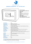
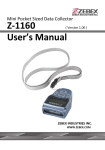
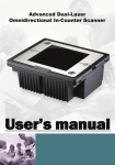
Important
This equipment grnerates, uses and can radiate radio frequency
energy. If not installed and used in accordance with the instructions
in this manual, it may cause interference to radio communications.
The equipment has been tested and found to comply with the limits
for a Class B computing device pursuant to EN55022 and to Subpart J of Part 15 of FCC Rules. These specifications are designed
to provide reasonable protection against interference when
operated in a commercial environment.
USER’S MANUAL
ALPHA-30 SERIES
OMNI-DIRECTIONAL LASER SCANNER
For CE-countries:
- The Alpha-30 is in conformity with the CE standards. Please
note that a ZEBEX CE-Marked power supply unit should be used
to conform to these standards.
For USA & Canada:
- To be used with UL listed and CSA certified computers/POS
system.
Radio and television interference
Operation of this equipment in a residential area can cause
interference to radio or television reception.
This can be
determined by turning the equipment off and on. The user is
encouraged to try to correct the interference by one or more of the
following measures:
u
Re-orientate the receiving antenna
u
Relocate the device with respect to the receiver
u
Move the device away from the receiver
u
Plug the device into a different outlet so that the device
and the receiver are on different branch circuits
If necessary, the user should consult the manufacturer, an
authorized ZEBEX dealer or experienced radio/television technician
for additional suggestion. The user may find the following booklet
prepared by the Federal Communications Commission helpful:
“ How to ldentify and Resolve Radio-TV Interference Problems” .
This booklet is available from the U.S. Government Printing Office,
Washington, DC 20402, Stock No. 004000003454.
HEADQUARTERS
ZEBEX INDUSTRIES INC.
Mobile Computer Division
ZEBEX INDUSTRIES INC.
Auto ID Division
2F, 531-1, Chung-Cheng Road,
Hsin-Tien City, Taipei, Taiwan, R.O.C.
Tel. +886-2-2218-2018
Fax. +886-2-2218-8670
Web site:www.zebex.com.tw
e-mail:[email protected]
3F, 540-1, Chung-Cheng Road,
Hsin-Tien City, Taipei, Taiwan, R.O.C.
Tel. +886-2-2218-3501
Fax. +886-2-2218-1415
Web site:www.zebex.com.tw
E-mail:[email protected]
USA
ZEBEX AMERICA INC.
GERMANY
ZEBEX Vertriebs-GmbH
Ilene Court, Building 11, Unit 4,
Belle Mead, New Jersey 08502, USA
Tel. +1-908-359-2070
Fax. +1-908-359-1272
Web site:www.zebex.com
E-mail:[email protected]
Stimpelwiese 2,
61250 Usingen, Germany
Tel. +49-1805-258443
Fax. +49-1805-258442
Web site:www.zebex.com.tw
E-mail:[email protected]
IMPORTANT NOTICE
TABLE OF CONTENTS
ZEBEX INDUSTRIES INC. MAKES NO WARRANTY OF ANY
KIND WITH REGARD TO THIS MATERIAL, INCLUDING,
BUT NOT LIMITED TO, THE IMPLIED WARRANTIES OF
MERCHANT ABILITY AND FITNESS FOR A PARTICULAR
PRYPOSE. ZEBEX INDUSTRIES INC. SHALL NOT BE
LIABLE FOR ERRORS CONTAINED HEREIN OF FOR
INCIDENTAL
CONSEQUENTIAL
DAMAGES
IN
CONNECTION WITH THE FURISHING, PERFORMANCE,
OR USE OF THESE MATERIALS.
Copyright 1997 by
iii
PREFACE
CHAPTER 1
1
THE ALPHA-30
1.1
Unpacking The Alpha-30
2
1.2
Scanning Bar Codes With The Alpha-30
3
1.3
Scanner Labeling
5
1.4
Maintaining The Scanner
7
1.5
Controlling The Scanner From The POS System
7
ZEBEX INDUSTRIES INC.
INSTALLING THE ALPHA-30
9
2.1
Installing The Scanner On a Counter Surface
10
2.2
Installing The Scanner Using The US-30 Universal Stand
13
CHAPTER 2
All other registered trade marks are registered companies’
property. ZEBEX is a registered trade mark of ZEBEX
INDUSTRIES INC.
APPENDIX 1
All rights reserved, reproduction of this document or any
portion of its contents is not allowed without the specific
written consent of ZEBEX INDUSTRIES INC.
CONNECTOR TYPES AND PIN OUT CONFIGURATION
A.1. Pinout Configuration For The Data Port Of the Scanner
17
18
A.2. Connector Types And Pin-Out Configuration For Us-30 Universal Stand And P/N 53110
nternal Cable Adaptor
20
Printed In January, 1997
APPENDIX 2
TECHNICAL SPECIFICATION
22
APPENDIX 3
TROUBLE SHOOTING
25
C.1. Trouble Shooting
i
26
ii
PREFACE
ALPHA-30 is a high performance omni-directional presentation laser
scanner. Bar code labels are read by presenting the labels to the
scanner. Scanning labels with ALPHA-30 hardly requires any arm
movement. As a result only little free space on the counter top is
required.
ALPHA-30 can be fixed either on a counter surface or on a US-30
universal stand. The US-30 universal stand allows you to direct the
scan pattern in a way that is optimal for your application by
adjusting the scanner window forward, backward, right or left.
ALPHA-30 reads most all popular bar-code symbologies. An
outstanding feature of ALPHA-30 is its programmable sleep mode.
If the scanner is not used within a programmable period of time, the
scanner turns off automatically. The scanner can be waked up by
pressing the switch on the top of the scanner or on the US-30 stand.
CHAPTER 1
THE ALPHA-30
ALPHA-30 is available in two versions. Each version features a
specific dual interface combination for communication with the POS
system. The dual interface combinations are: RS-232C/OCIA and
IBM RS-485/Keyboard Wedge.
This manual contains two chapters and three appendices. The first
chapter describes ALPHA-30 and its general features. ALPHA-30
can be installed on a counter surface or a US-30 universal stand.
Instructions for both installations are described in the second
chapter. The default settings can be changed with the bar-code
labels from the Configuration Guide that comes with the scanner.
Appendix A gives the pin out configuration for the Data ports of the
scanner. The pin out configuration is necessary if you want to
make a new cable for communication with the POS/computer.
Appendix B gives an overview about the technical specifications of
0. Go to Appendix C for troubleshooting if the scanner is not
working properly.
iii
1
1.1 UNPACKING ALPHA-30
Take out the scanner and its accessories from the box and packing
material. Make sure you have received all of the items ordered by
referring to the packing list. Check if the scanner and accessories are
received in good condition. Refer to the upper figure 1.4 on page 5 to
locate the label with the interface information and make sure that the
interface of the scanner corresponds with the POS systems interface.
Immediately contact your dealer if there is anything missing or appears to
be damaged, or if the supported interface does not correspond with the
POS system interface.
The various parts of ALPHA-30 are:
ON/OFF Switch
−
Control the main power of ALPHA-30.
Sleep Mode Switch
−
When ALPHA-30 enters into the sleep mode,
the scanner can be waked up by pressing this
switch. The sleep mode feature can be
programmed using the menu labels from the
Programming Guide.
NOTE: The default value for the sleep mode
time-out is set to 30 minutes. When
the scanner is in sleep mode, the LED
is intermittently flashing red.
Sleep mode switch
(RE-START SWITCH)
LED
−
A red LED indicates the scanner is ready to
read a bar code while a green LED indicates
a good read.
Good Read Buzzer
−
If the data is captured correctly, the buzzer
will be heard.
Both the volume and
frequency are programmable using the menu
labels from the Programming Guide.
Universal stand (US-30)
−
This stand allows you to direct the scan
pattern in a way that is the best for your
application by adjusting the scanner window
forward, backward, right or left.
LED
Good read buzzer
Good read buzzer
(POWER ON/OFF SWITCH)
Universal stand
(RE-START SWITCH)
1.2 SCANNING BAR CODES WITH ALPHA-30
ALPHA-30 omni-directional laser scanner features a 7 directions scan field
with a 24 lines scan pattern. Bar code labels can be read easily by
presenting them to the scanner.
The scanner’ s scan volume is illustrated in figure 1.2 on the next page.
The density of the pattern has an optimum at 70 mm (3 inches) from the
scanner window, but bar codes can be read up to 250 mm (10 inches) from
the scanner window.
The scanner window can be adjusted forward, backward and left or right
which allows you to direct the optimal reading zone in a way that suits your
application most.
Figure 1.1
2
3
Important:
Please prevent from touching the scan window with the
n
articles to be scanned. This might cause tinny scratches
which consequently can have a negative influence on the
scanning performance.
1.3 SCANNER LABELLING
There are two labels on the housing of ALPHA-30 as illustrated in figure 1.4
(for IBM validated scanner these two labels are also present at the exterior
of the scanner). In addition, there are two labels visible through the
scanner window. All the labels are attached by the manufacturer and
should not be removed.
ALPHA-30
SERIES
OMNI-DIRECTIONAL LASER SCANNER
MODEL NO: ALPHA-30 K/I
S/N:******** P/N:93010
Figure 1.2
How to scan a bar code label with ALPHA-30 is very simple: simply by
presenting the label of the product to the scanner as illustrated here in
figure 1.3.
This device
complies with
part 15 of
the FCC rules
1.Move the label to the scanner
.
Bar code is read (green led)
2.Move the label from the scanner.
You will find a serial number on the scanner. This number is underneath
the bar code label as illustrated in figure 1.4. This official registration
number is strictly related to the device. The dealer can ask for this number
when the scanner needs servicing.
sp
ch ecia
ew l
in of
g- fe
gu r
m
1
Figure 1.4
2
Figure 1.3
4
5
Adjustments: Do not attempt any adjustments or alteration of this product.
Do not remove the protective housing of the scanner. There are no userserviceable parts inside.
CAUTION: Use of controls or adjustments or performance of
procedures other than those specified herein may result in hazardous
laser light exposure.
CAUTION
LASER LIGHT
DO NOT STARE INTO BEAM
670mm LASER DIODE,1.0mW MAX OUTPUT
IEC 825-1(1993)CLASS 1,US 21 CFR 1040 CLASS
lla
LASER PRODUCT
Figure 1.5
Laser Safety
ALPHA-30 laser scanner complies with safety standard IEC 825-1 (1993)
for a Class I laser product. It also complies with U.S. 21CFR1040 as
applicable to a Class IIa laser product. Avoid long term viewing of direct
laser light.
1.4 MAINTAINING THE SCANNER
ALPHA-30 laser scanner rarely needs any maintenance.
Only an
occasional cleaning of the scanner window is necessary in order to remove
dirt and fingerprints. The cleaning of the scanner window can be done
during operation with a soft lint-free cloth and a non-abrasive glass spray
cleaner.
1.5 CONTROLLING THE SCANNER FROM THE POS SYSTEM
ALPHA-30 can be controlled from the POS system via the RS-232C
interface. Controlling can be accomplished by transmitting the following
single byte commands to the scanner. The default setting of the
commands are as follows (more details are available upon request):
ASCII Code
Function
Byte is Also Called:
Optical: The use of optical instruments with this product will increase eye
hazard.
Optical instruments include binoculars, microscopes and
magnifying glasses but do not include eye glasses worn by the user.
OE Hex
enable (resumes disable)
Shift Out or <Ctrl-N>
OF Hex
disable
Shift In or <Ctrl-O>
Radiant Energy: ALPHA-30 uses a low-power laser diode operating at
670nm in an opto-mechanical scanner resulting less than 0.6 mW peak
output power. Laser light observed at 13cm (5.1 inches) above the window
through a 7 mm (0.28 inches) aperture and averaged over 1000 seconds is
less than 3.9µW PER CDRH Class IIa specification. Do not attempt to
remove the protective housing of the scanner, as unscanned laser light
with a peak output up to 0.8mW would be accessible inside.
05 Hex
power-up re-initialization
ENQ or <Ctrl-E>
12 Hex
sleep
DC2 <Ctrl-R>
14 Hex
wake up (resumes sleep)
DC4 <Ctrl-T>
Laser Light Viewer: The scanner window is the only aperture through
which laser light may be observed on this product. A failure of the scanner
motor, while the laser diode continues to emit a laser beam, may cause
emission levels to exceed those for safe operation. The scanner has
safeguards to prevent this occurrence. If, however, a stationary laser
beam is emitted, the failing scanner should be disconnected from its power
source immediately.
6
When the scanner is disabled, the motor of the scanner will stay on until
the scanner goes into sleep mode.
7
POS system
Scanner control
CHAPTER 2
+12V dc
-12V dc
+5V dc
*
Figure 1.6
8
INSTALLING THE ALPHA-30
9
There are two different ways to install ALPHA-30 depending on how you
want to use it: fix it on a counter surface or on a US-30 universal stand.
Data port 2.Connect the communication
cable to this port if the host system
features the OCIA or KBW interface
To install on a counter surface, please refer to Section 2.1.
To install on the US-30 universal stand, please refer to Section 2.2.
As there are many computer devices on the market, ZEBEX provides a
large number of communication cables as options. Make sure you order
the right cable to connect the scanner to your POS or computer.
Data port 1.Connect the communication
cable to this port if the host system features
the RS232C or IBM RS485 interface
Notice:
It is our advice to turn off your POS system before starting
n
the installation of the scanner. By following this precaution,
you can avoid your computer from electronically being
damaged.
It is also our advice to install the scanner in an air circulated
n
place out of the direct sunlight.
2.1. INSTALLING THE SCANNER ON A COUNTER SURFACE
You are advised to mount the scanner in a fixed counter surface position
by following the procedure here below.
1. Locate the small hole at the back cover of the scanner. Press it with the
tip of a stick to remove the back cover of the scanner as illustrated in
figure 2.1.
Figure 2.2
2.
Slit for cables
Figure 2.1
10
3.
If the POS system is the RS-232C or IBM 485 interface, plug the
communication cable with the 8 pin modular jack into Data port 1, or if
the POS system interface is OCIA or Keyboard Wedge, plug the
communication cable into Data port 2. Plug the other end of the cable
into the appropriate serial port of your POS or computer. Use the
ZEBEX universal power supply. Lead the cables through the scanner
as illustrated in figure 2.2.
Important:
If the POS system is an IBM 4683/4684 POS, the scanner
n
with IBM RS-485 interface should only be connected to port
17 of the POS.
If the POS system is an IBM 4693/4694 POS, the scanner
n
with IBM RS-485 interface should only be connected to port
9E of the POS.
Use the back cover as a template to mark the places for the mounting
holes at the counter surface and bore two holes.
11
4.
Lead the communication cable and power supply cable through the slit.
Then use the two screws to fasten the back cover to the surface as
illustrated here follows:
2.2. INSTALLING THE SCANNER USING THE US-30 UNIVERSAL STAND
To install the scanner on a US-30 universal stand, the cables should be led
through the central hold of the US-30 universal stand to be connected to
the scanner. The stand should be mounted to the counter top first and then
the scanner to the stand.
to Data port 1 of scanner
to socket for Fan
Notice:
We strongly suggest you to use two screws to mount the
scanner on the counter surface.
n
to Data port 2
of sacnner
to socket for
power supply
coming form
POS system
Follow the next few steps to mount the stand on a counter:
1.
Figure 2.3
5.
6.
Place the scanner as illustrated in figure 2.4 and rotate the scanner
around the cover. Make sure the connectors and cables are placed
properly as illustrated in the figures to allow easy attachment of the
scanner to the back cover. Press the scanner until a “ click” is heard.
Turn on the POS system.
If you prefer to mount the stand with two screws, on the counter top
where the scanner is to be installed, mark the two places for the
mounting holes Refer to the figure for the relative position and the
diameter. Do not mount the stand to the counter top yet.
Figure 2.5
Figure 2.4
You may start scanning bar-codes as soon as the scanner is installed. If
you want to change the default setting of the scanner, go to the
“ Programming Guide” that is included with the scanner.
2.
3.
4.
12
Lead the communication cable with the 8 pin modular jack and the
power supply cable from the bottom through the stand. Refer to figure
2.6 to locate the hole through which the cable should be led.
Press the small hole at the back cover of the scanner with the tip of a
stick to remove the back cover, as illustrated in figure 2.1.
Plug the communication cable with the 8 pin modular jack in the
appropriate Data port of the scanner. Refer to figure 2.2 for the Data
port applicable to the interface used. Plug the other end of the cable
into the appropriate serial communication port of the POS system.
Important:
13
n
n
If the POS system is an IBM 4683/4684 POS, the scanner with
IBM RS-485 interface should only be connected to port 17 of the
POS.
If the POS system is an IBM 4693/4694 POS, the scanner with
IBM RS-485 interface should only be connected to port 9E of the
POS.
to data port 2 of scanner
to data port 1 of scanner
6. Place the scanner onto the US-30 universal stand and rotate the
scanner as shown in figure 2.8. Make sure that the connectors and cables
are placed as indicated in the figures, such to allow easy attachment of the
scanner to the back cover. Press the scanner until a “ click” is heard.
to socket for power supply
to socket for fan supply
Lead the commumication cable
through this hole if it should be
connected to Data port 1.
Figure 2.6
5.
Use either screws or the double sided tape to fasten the stand at the
bottom of the plate.
Figure 2.8
7. Switch on the POS system.
You may start scanning bar-codes as soon as the scanner is installed. If
you want to change the default setting of the scanner, go to the
“ Programming Guide” that is included with the scanner.
ø4.5mm(2x)
Figure 2.7
15
15
This page is intentionally left blank.
APPENDIX A
CONNECTOR TYPES AND PIN OUT
CONFIGURATION
16
17
A.1. PINOUT CONFIGURATION FOR THE DATA PORT OF THE SCANNER
Pin Definition For Dual Interface Version RS-232C/OCIA
RS-232C Interface
Data Port 1
Pin
1
2
3
4
5
6
7
8
Data port 2
PIN1
PIN8
Description
CTS
RD
TX
RTS
GND
N.C.
OCIA Interface
Data Port 2
Direction
input
input
output
output
-
for factory use only
Pin
1
2
3
4
5
6
7
8
Description
lfid
DATA
DATA RTN
CLOCK IN
GND
CLOCK IN RTN
RESET
RESET RTN
Direction
input
output
output
input
input
input
input
Pin Definition For Dual Interface Version IBM RS-485/KB Wedge
IBM RS485 Interface
Data Port 1
#1
Fan socket
#4
PIN8
PIN1
#1
Power supply port
Data port 1
KB Wedge Interface
Data Port 2
Pin Description
Direction
1
N.C.
2
IO-A
input/output
3
IO-B
input/output
4
N.C.
5
GND
6
N.C.
7
for factory use only
8
Pin
1
2
3
4
5
6
7
8
Description
lfid1
KB_DATA
KB_CLCK
PC_DATA
PC_GND
PC_ CLCK
PC_5V
lfid2
Pin Definition For Power Supply Port and Fan Port
Power Supply port
Figure A.1
18
Pin
1
2
3
4
Fan port
Description
+5V
-12V
+12V
GND
Pin
1
2
3
19
Description
+5V
RE-START
GND
Direction
input
output
input
input
input
input
input
input
A.2. CONNECTOR TYPES AND PIN-OUT CONFIGURATION FOR US30 UNIVERSAL STAND AND P/N 53110 INTERNAL CABLE ADAPTOR
US-30, the universal stand, and the P/N 53110 Internal cable adaptor are
good for ALPHA-30. The pin-out of the D-Sub 25pin communication port
varies according to the interface versions of the US-30. Please refer to p
21 for detailed information. Besides, US-30 supports an auxiliary RS-232C
port. When it works with the Alpha-30R/A version, it can be connected
with an external RS-232C hand-held scanner (of any type).
Power Supply Port
4
5
13
3
1
25
RS-232/OCIA Interface
IBM 468x/469x KB Wedge Interface
Pin
Description
Description
1
Shield GND
Shield GND
2
TX
RS232
C
Inter
face
I0-A (input/output)
IBM
I0-B (input/output)
RS-485
3
RX
4
RTS
5
CTS
7
GND
11/18
for factory use only
12
CLOCK IN RTN
13
DATA RTN
14
CLOCK IN
15
DATA
KB DATA
24
RESET
PC 5V output
9
lfid1
lfid1
10
RESET RTN
lfid2
2
1
D-SUB 25PIN
Communication Port
D-Sub 25 Pin Communication Port
N.C.
N.C.
GND
for factory use only
PC CLOCK
OCI
A
Inter
face
KB CLOCK
PC DATA
6, 8, 16, 17, 19, 20, 21, 22, 23, 25
14
1
5
6
9
5
Auxiliay Port
3
13
1
4
25
14
2
1
D-SUB 25PIN
Communication Port
Power Supply Port
Figure A.2
N.C.
Power Supply Port
Auxiliary Port (for US-30 only)
Pin
1
2
3
4
5
Shell
Pin
1
2
3
4
5
6
7
8
9
Description
GND
+5V
+12V
-12V
GND
Shield
Figure A.3
20
21
Description
N.C.
RX
TX
N.C.
GND
N.C.
N.C.
N.C.
+5V DC output
Key
boar
d
Wed
ge
Inter
face
SPECIFICATIONS
ELECTRICAL
Supply Voltage
DC Input To Scanner
Interfaces
100~240V AC, 50/60 Hz
+5V DC, 450mA,
+12V DC, 150mA
-12V DC, 50mA
RS232C Interface
Keyboard Emulation
(IBM PC/AT, PS/2 compatible)
OCIA Interface
IBM RS-485 (IBM 4683/4684/4693/4694) Interface
OPTICAL
Light Source
Depth Of Field
Scan Pattern
Scan Rate
670 ± 5 nm visible laser diode
250 mm (10 inches)
7 direction scan field, 24 line scan pattern
2400 scans / second
APPENDIX B
TECHNICAL SPECIFICATION
ENVIRONMENT
Operating Temp.
Humidity
PHYSICAL
Weight
Dimensions
o
O
0 C ~ 40 c
20% ~ 95% RH
(non-condensing dew)
700 g (excl. stand)
L x W x D: 160 x 150 x 75 mm
: 6.29 x 5.90 x 2.95 inch
150.0(5.90")
160.0(6.29")
75.0(2.95")
150.0(5.90")
Figure B.1
22
23
25.0(0.98")
70.25(2.76")
7.5
90.0(3.54")
SPECIFICATIONS
DECODING
Bar Code Types
SAFETY
Laser Safety
Electrical Safety
Flammability Ratio
EM COMPATIBILITY
Radio And TV
Interference
Radio Frequency
Immunity
ElectroStatic Discharge
(ESD)
Radio Frequency EMimmunity
Electrical Fast Transient
EAN/UPC/JAN + Add-on Code 128, EAN 128,
Code 39, Code 32, Codabar, Interleaved 2 of 5
IEC 825-1 (1993) Class I, U.S. 21CFR1040 Class IIa
EN 60950 second edition
UL1950, c-UL (according CSA22.2.950)
94V-0
EN 55022 Class B (1994), FCC part 15 Class B
(1992)
EN 50082-1 (1992)
APPENDIX C
IEC 801-2 (1991)
IEC 801-3 (1984) / ENV 50140 (1993)
TROUBLE-SHOOTING
IEC 801-4 (1988)
24
25
C.1 Trouble-shooting
This section contains information about how to solve problems that you
may encounter when operating the scanner. If troubles occur, please refer
to the following diagnostic tips as a mean to solve the trouble. However,
before referring to the tips, make sure that the scanner is installed as
instructed in Chapter 2 and that all cables are properly connected. If the
problem remains, contact your dealer.
Problem
Problem
Diagnostic Tips
The LED remains green.
u
The scanner is continuously
seeing a bar-code. Remove all
bar-code labels out of the scan
volume of the scanner and try
again.
u
The scanner cannot send the
data to the POS system. There
is no proper handshaking
between the scanner and the
host. Make sure that all cables
are connected and your POS
system is ready to receive data.
The scanner does not accept more
than two or three barcode labels.
u
There is no proper handshaking
with the POS system. Switch
on the POS system and check
connection and communication
settings.
The LED is orange.
u
The laser in not functioning.
The laser is either defect or
switched off by the temperature
protection circuit. Turn off the
scanner for 5 minutes and try
again. Make sure the scanner
has enough air ventilation and is
not placed in direct sunlight.
Diagnostic Tips
The scanner is on but can not read u The scanner window is dirty.
bar codes. The LED is red.
Clean the scanner window as
described in the Maintenance
section.
u
The presented bar-code type is
not enabled. Select the barcode type with the Configuration
Guide.
u
The scanner is disabled by the
host. Refer to Section 1.5.
u
The bar-code type you
presented to the scanner is not
supported by ALPHA-30.
The scanner is on, but the motor is
not rotating. A bar code cannot be
read.
The LED is intermittently
flashing red.
u
The scanner has entered into
the sleep mode. Press the
switch on the top or front of the
scanner to wake up the scanner
(or use the wake protocol.
Refer to section 1.5)
The LED is alternating red/green and
beeps are heard.
u
Possible failure of the scanning
safeguard circuit. Disconnect
the scanner from its power
source immediately and contact
your dealer.
26
27
Problem
Diagnostic Tips
A barcode is read by the scanner
but not accepted by the POS
system.
u
The communication cable is not
connected to the serial port of
your POS system. Refer to the
manual of your POS system to
locate the serial port.
u
The communication settings of
the system and scanner do not
match. Adjust the settings in
order to be equal for both
device.
u
The communication cable does
not suit your POS system..
Contact your dealer for the
correct communication cable.
u
The data format of the label is
not supported by the software
running on the POS system.
28