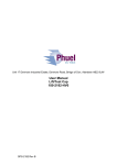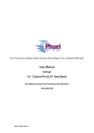
1
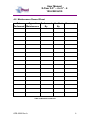
Unit 17 Denmore Industrial Estate, Denmore Road, Bridge of Don, Aberdeen AB23 8JW
User Manual
X-Over 9.5” – 4 x 9” - 4
150-2522-HV0
OPS-2522 Rev A
User Manual
X-Over 9.5” – 4 x 9” - 4
150-2522-HV0
Table of Contents
Revision History ........................................................................................... ii
Safety .............................................................................................................. iii
1 Introduction ............................................................................................... 1
1.1
General .............................................................................................. 1
1.2
Product Identification ......................................................................... 1
2 Technical Specification ............................................................................. 2
3 Operation .................................................................................................. 3
3.1
Pre Job .............................................................................................. 3
3.2
During Job ......................................................................................... 3
3.3
Post Job............................................................................................. 3
4 Maintenance ............................................................................................. 4
4.1
Introduction ........................................................................................ 4
4.2
Schedule............................................................................................ 4
4.2.1
Pre & Post Job............................................................................ 4
4.2.2
Yearly ......................................................................................... 4
4.2.3
Five Yearly.................................................................................. 4
4.3
Safety ................................................................................................ 4
4.4
Tools .................................................................................................. 5
4.5
Redress Procedure ............................................................................ 5
4.5.1
Dis-Assembly.............................................................................. 5
4.5.2
Re-Assembly .............................................................................. 5
4.6
Maintenance Record Sheet ............................................................... 6
5 Testing ...................................................................................................... 7
6 Parts List and Drawings ............................................................................ 8
7 Spares ...................................................................................................... 9
7.1.1
Individual Items........................................................................... 9
Table 1: Technical Data ................................................................................... 2
Table 2: Maintenance Record .......................................................................... 6
Table 3: Parts List ............................................................................................ 8
Figure 1: X-Over 9.5 – 4 x 9 - 4........................................................................ 2
Figure 2: X-Over Assembly .............................................................................. 8
OPS-2522 Rev A
i
User Manual
X-Over 9.5” – 4 x 9” - 4
150-2522-HV0
Revision History
Issue, Release Date
Rev A, 11 Dec 08
OPS-2522 Rev A
Description
Initial Issue
ii
User Manual
X-Over 9.5” – 4 x 9” - 4
150-2522-HV0
Safety
WARNING: Trapped air requires considerable time to compress and
when it is compressed is highly dangerous. It has enough stored
energy to separate parts with considerable force.
All pressure equipment has a particular pressure rating and care must be
taken to ensure that no item is used in a situation that may cause its working
pressure to be exceeded.
All personnel involved in pressure testing must be formally trained, competent
and utilising the appropriate PPE.
Ensure the identification band/plate is fitted and is displaying the correct
information as per the Tag Sheet/Index
This equipment and the equipment it is attached to is heavy never position
yourself below a suspended load
OPS-2522 Rev A
iii
User Manual
X-Over 9.5” – 4 x 9” - 4
150-2522-HV0
1 Introduction
1.1 General
The X-Over riser is designed to allow interconnection between equipment with
9½”- 4 Acme connectors to equipment with 9’’ – 4 Acme connections.
This user manual serves as an introduction to the equipment and contains the
relevant specifications, operation, planning and maintenance instructions,
parts list and drawings.
1.2 Product Identification
Phuel products are identified by a unique serial number that facilitates full
product traceability. Each product is supplied with a documentation pack that
contains product certification and material/inspection reports. The serial
number is always etched on the surface of the product but can sometimes be
difficult to find or read after painting. A customer identification number is also
included to allow the customer to track the asset in their system.
A stainless steel band secures the nameplate tag that is stamped with the
information shown below. This tag should be located in the first instance to
ensure that this manual refers to the correct equipment.
PHUEL OIL TOOLS LTD
DESCRIPTION & SIZE
CUSTOMER ID No
PHUEL ID No 06-XXX-XX
MWP & SERVICE
TEST DATE
OPS-2522 Rev A
1
User Manual
X-Over 9.5” – 4 x 9” - 4
150-2522-HV0
2 Technical Specification
Part Number
Connection
Maximum Working Pressure
Test Pressure
Service
Weight
Overall Length
Make Up Length
150-2521-HV0
9.5 – 4 Acme Pin
9 – 4 Acme Box
6,500 Psi
10,000 Psi
H2S
226 lbs
20.92”
17.3”
Table 1: Technical Data
Figure 1: X-Over 9.5 – 4 x 9 - 4
OPS-2522 Rev A
2
User Manual
X-Over 9.5” – 4 x 9” - 4
150-2522-HV0
3 Operation
All operations to be carried out by suitably qualified and competent
personnel
3.1 Pre Job
•
•
•
•
•
•
•
•
•
•
•
Ensure thread protectors are fitted
Check maintenance record sheet and ensure the equipment has been
maintained by competent personnel
Check all certification is in date
Confirm information band is fitted and correct
Ensure equipment is suitable for the maximum working pressures and
services involved
Ensure ‘O’ ring is seated correctly and there are no signs of damage
Ensure threads are clean
Inspect for signs of damage
Pressure test to 1.2x the maximum well pressure
Ensure all connections are tight
Ensure that spare o-rings are available and sent with the equipment.
3.2 During Job
•
Avoid excessive movement
3.3 Post Job
•
•
•
Inspect for signs of damage and report any findings
Ensure threads are cleaned and the re-greased
Ensure thread protectors are fitted
OPS-2522 Rev A
3
User Manual
X-Over 9.5” – 4 x 9” - 4
150-2522-HV0
4 Maintenance
All maintenance to be carried out by suitably qualified and competent
personnel
4.1 Introduction
Regular maintenance of the equipment using Phuel redress kits or Phuel
approved parts is essential to its continued safe operation. Ensure that the pre
and post job operating procedures are followed and that maintenance records
are kept.
4.2 Schedule
The maintenance schedule may be governed by international or company
standards and the following is considered to be the minimum requirements.
4.2.1 Pre & Post Job
Refer to Section 3.1 and Section 3.3 for details
4.2.2 Yearly
•
•
•
•
•
•
•
•
Disassemble X-Over (see 4.5.1) clean and degrease all components
Inspect the condition of all sealing surfaces and surface coatings
Re-coat threads and sealing surfaces if necessary. If in doubt contact
Phuel Oil Tools Ltd
Replace all elastomeric seals with items from redress kit (see spares
Section 7)
Regrease components
Re-assemble (see 4.5.2)
Pressure test to maximum working pressure in accordance to testing
procedure (see 5)
Inspect paint work and repair as necessary
4.2.3 Five Yearly
•
•
•
Yearly Maintenance (plus the following)
Carry out 100% surface NDE on all surfaces
Pressure test to test pressure witnessed by certifying authority
4.3 Safety
•
•
Many of the components are heavy and should not be lifted without
lifting aids.
Ensure all pressure testing is carried out in the appropriate testing area
by suitably qualified personnel.
OPS-2522 Rev A
4
User Manual
X-Over 9.5” – 4 x 9” - 4
150-2522-HV0
•
•
•
•
Wear appropriate personal protective equipment.
Do not over exert yourself while using torque wrenches. Use
appropriate mechanical advantages when available.
Ensure that all tools and equipment are in good condition and are
suitable for the intended use.
Clear up any fluid spills immediately to avoid slips.
4.4 Tools
The following tools are required:
• Wire Brush
• 3/8 hex Allen key
4.5 Redress Procedure
4.5.1 Dis-Assembly
•
•
•
•
Remove stop pins and washers
Remove split ring
Remove collar
Remove ‘O’ ring and discard
4.5.2 Re-Assembly
•
•
•
•
Fit ‘O’ ring to test cap
Fit collar
Fit split rings and make up until all four holes in the split ring are
aligned with the holes in the collar
Fit stop pins and washers
OPS-2522 Rev A
5
User Manual
X-Over 9.5” – 4 x 9” - 4
150-2522-HV0
4.6 Maintenance Record Sheet
Date
Type of
Performed
Performed Maintenance
By
Verified
By
Comments
Table 2: Maintenance Record
OPS-2522 Rev A
6
User Manual
X-Over 9.5” – 4 x 9” - 4
150-2522-HV0
5 Testing
All testing is to be carried out in the designated test area and by suitably
qualified and competent personnel.
WARNING: Trapped air requires considerable time to compress and
when it is compressed is highly dangerous. It has enough stored
energy to separate parts with considerable force.
•
•
•
•
•
•
•
•
Fit appropriate test caps and blanking plugs
Fill with testing fluid bleeding off any air within the system
Apply a pressure of 500 psi and ensure pressure holds for a minimum
of 10 minutes
Increase pressure to 6,500 psi (Maximum Working Pressure), allow to
stabilise and maintain this pressure until it is evident there are no
apparent leaks. (Testing to be carried out to Test pressure when
decreed by maintenance schedule)
Bleed off pressure, drain test fluid and dry
Remove test caps
Apply coating of de-watering solution to protect the bore and threads
Fit thread protectors
On completion of all maintenance ensure the maintenance record sheet (Para
4.6) is completed
OPS-2522 Rev A
7
User Manual
X-Over 9.5” – 4 x 9” - 4
150-2522-HV0
6 Parts List and Drawings
Item Number
1
2
3
4
5
6
100
101
Part Number
150-2520-480
117-2381-480
117-2382-480
110-2329-3A4
WNL-0580-STL
801-0443-V90
910-2551-N66
910-2156-N66
Quantity
1
1
1
4
4
1
1
1
Description
CROSSOVER 9.5"-4 PIN X 9"-4 BOX
SPLIT COLLAR 9 1/2"-4 (SPLIT TYPE)
SPLIT RING
STOP PIN
Nord Lock Washer (M12)
O-Ring - B.S Size 443
9-1/2 MALE PROTECTOR
9-4 ACME FEMALE PROTECTOR
Table 3: Parts List
Note: Thread protectors (items 100 and 101) not shown on Assembly Drawing
(Figure 2)
Figure 2: X-Over Assembly
OPS-2522 Rev A
8
User Manual
X-Over 9.5” – 4 x 9” - 4
150-2522-HV0
7 Spares
Use only spares supplied or approved by Phuel Oil Tools Ltd.
It is recommended that sufficient quantities of the following spares be
maintained to ensure that the equipment is always available when required.
Elastomeric spares are supplied in Viton material as standard. Many other
materials are available please specify when ordering.
Part No
801-0443-V90
Qty
1
Description
O-Ring - B.S Size 443
Comments
7.1.1 Individual Items
Individual items may be ordered as required using the part number specified
Note: O-Rings conform to industry standards and may be substituted with
those from other suppliers -– at the sole risk of the user
OPS-2522 Rev A
9