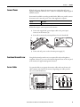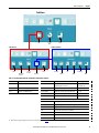
1
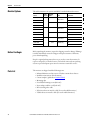
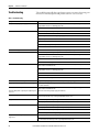
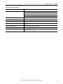
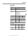
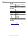
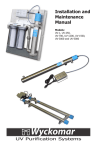
User Manual
Standard Industrial Monitors
Catalog Numbers 6176M-15VN, 6176M-15VT, 6176M-15PN, 6176M-15PT, 6176M-17VN, 6176M-17VT, 6176M-17PN,
6176M-17PT, 6176M-19VN, 6176M-19VT, 6176M-19PN, 6176M-19PT
Important User Information
Solid-state equipment has operational characteristics differing from those of electromechanical equipment. Safety
Guidelines for the Application, Installation and Maintenance of Solid State Controls (publication SGI-1.1 available from
your local Rockwell Automation sales office or online at http://www.rockwellautomation.com/literature/) describes some
important differences between solid-state equipment and hard-wired electromechanical devices. Because of this difference,
and also because of the wide variety of uses for solid-state equipment, all persons responsible for applying this equipment
must satisfy themselves that each intended application of this equipment is acceptable.
In no event will Rockwell Automation, Inc. be responsible or liable for indirect or consequential damages resulting from the
use or application of this equipment.
The examples and diagrams in this manual are included solely for illustrative purposes. Because of the many variables and
requirements associated with any particular installation, Rockwell Automation, Inc. cannot assume responsibility or
liability for actual use based on the examples and diagrams.
No patent liability is assumed by Rockwell Automation, Inc. with respect to use of information, circuits, equipment, or
software described in this manual.
Reproduction of the contents of this manual, in whole or in part, without written permission of Rockwell Automation,
Inc., is prohibited.
Throughout this manual, when necessary, we use notes to make you aware of safety considerations.
WARNING: Identifies information about practices or circumstances that can cause an explosion in a hazardous environment,
which may lead to personal injury or death, property damage, or economic loss.
ATTENTION: Identifies information about practices or circumstances that can lead to personal injury or death, property
damage, or economic loss. Attentions help you identify a hazard, avoid a hazard, and recognize the consequence.
SHOCK HAZARD: Labels may be on or inside the equipment, for example, a drive or motor, to alert people that dangerous
voltage may be present.
BURN HAZARD: Labels may be on or inside the equipment, for example, a drive or motor, to alert people that surfaces may
reach dangerous temperatures.
IMPORTANT
Identifies information that is critical for successful application and understanding of the product.
Allen-Bradley, Rockwell Software, Rockwell Automation, and TechConnect are trademarks of Rockwell Automation, Inc.
Trademarks not belonging to Rockwell Automation are property of their respective companies.
Summary of Changes
This manual contains new and updated information. Changes throughout this
revision are marked by change bars, as shown to the right of this paragraph.
New and Updated
Information
This table contains the changes made to this revision.
Topic
Page
Added ‘Preface Objectives’ title and updated section information
7
Added ‘Abbreviations’ section
7
Updated hypertext links for Rockwell Automation websites
7, 12, 42
Added Bezel column to table in ‘Monitor Options’ section
10
Consolidated Environment and Enclosure Information and European Union Directive information
into new ‘Installation Precautions’ section
12
Added Important table and cross-references in ‘Installation Guidelines’ section
13
Added monitor tilt information and illustration in ‘Installation Guidelines’ section
13
Removed mounting clearance information from ‘Panel Mounting’ section for new ‘Mounting
Clearance Requirements’ section
14
Consolidated all dimensions into one illustration and one table in ‘Monitor Dimensions’ section
15
Added ‘Install the Monitor’ section title and introductory paragraph
15
Added table for replacement panel mounting clips
15
Consolidated two mounting clip illustrations into Figure 1
16
Removed rack mounting information for 1550M and 1750M monitors
17
Added step 2 and illustration to ‘Mounting the Monitor on a Bench or Tabletop’ subsection
19
Modified illustration in ‘Monitor Connections’ section
19
Updated information and illustration in ‘Connecting the USB and Optional USB Touchscreen
Interface’ subsection
22
Added the ‘Installing the Touchscreen Driver’ subsection
22
Added the ‘Performing a Calibration’ subsection
22
Changed Chapter 3 title from ‘Video Setup’ to ‘Display Configuration’
25
Added Tip table to ‘Check and Change the Display Resolution’ section
25
Changed OSD lock access time from eight to three seconds
26
Changed section title from ‘Perform the Automatic Video Adjustment Function’ to ‘Use the Auto
Adjust Control’
27
Updated information and Important table in ‘Use the Auto Adjust Control’ section
27
Added Important table to ‘Use the Auto Adjust Control’ section
27
Updated information in ‘General OSD Menu Navigation Guidelines’ subsection
28
Added cross reference to Tip table for ‘Brightness and Contrast Menu’ subsection
30
Removed ‘Auto’ button and corresponding information in ‘Color Menu’ subsection
31
Added OSD Submenu and Rotation Submenu tables in ‘Tool Menu’ subsection
33
Added replacement screen covers table in ‘Clean the Monitor’ section
35
Updated and added information in Table 8, Display, in the ‘Specifications’ section
41
Added illustration to ‘HD-15 Video Connector’ section
45
Added illustration to ‘DVI Video Connector’ section
46
Rockwell Automation Publication 6176M-UM001D-EN-P - December 2012
3
Summary of Changes
Notes:
4
Rockwell Automation Publication 6176M-UM001D-EN-P - December 2012
Table of Contents
Preface
Preface Objectives. . . . . . . . . . . . . . . . . . . . . . . . . . . . . . . . . . . . . . . . . . . . . . . . . . 7
Purpose of This Manual . . . . . . . . . . . . . . . . . . . . . . . . . . . . . . . . . . . . . . . . . . . . 7
Abbreviations. . . . . . . . . . . . . . . . . . . . . . . . . . . . . . . . . . . . . . . . . . . . . . . . . . . . . . 7
Additional Resources . . . . . . . . . . . . . . . . . . . . . . . . . . . . . . . . . . . . . . . . . . . . . . . 7
Chapter 1
Monitor Features
Chapter Objectives. . . . . . . . . . . . . . . . . . . . . . . . . . . . . . . . . . . . . . . . . . . . . . . . . 9
Monitor Overview . . . . . . . . . . . . . . . . . . . . . . . . . . . . . . . . . . . . . . . . . . . . . . . . . 9
Monitor Options . . . . . . . . . . . . . . . . . . . . . . . . . . . . . . . . . . . . . . . . . . . . . . . . 10
Before You Begin . . . . . . . . . . . . . . . . . . . . . . . . . . . . . . . . . . . . . . . . . . . . . . . . 10
Parts List . . . . . . . . . . . . . . . . . . . . . . . . . . . . . . . . . . . . . . . . . . . . . . . . . . . . . . . . 10
Chapter 2
Installation
Chapter Objectives. . . . . . . . . . . . . . . . . . . . . . . . . . . . . . . . . . . . . . . . . . . . . . .
Installation Precautions. . . . . . . . . . . . . . . . . . . . . . . . . . . . . . . . . . . . . . . . . . .
Environment and Enclosure Information. . . . . . . . . . . . . . . . . . . . . . .
European Union Directive . . . . . . . . . . . . . . . . . . . . . . . . . . . . . . . . . . . .
Installation Guidelines . . . . . . . . . . . . . . . . . . . . . . . . . . . . . . . . . . . . . . . . . . .
Required Tools . . . . . . . . . . . . . . . . . . . . . . . . . . . . . . . . . . . . . . . . . . . . . . . . . .
Mounting Clearance Requirements. . . . . . . . . . . . . . . . . . . . . . . . . . . . . . . .
Monitor Dimensions . . . . . . . . . . . . . . . . . . . . . . . . . . . . . . . . . . . . . . . . . . . . .
Install the Monitor . . . . . . . . . . . . . . . . . . . . . . . . . . . . . . . . . . . . . . . . . . . . . . .
Panel Mounting . . . . . . . . . . . . . . . . . . . . . . . . . . . . . . . . . . . . . . . . . . . . . .
Rack Mounting (1950M monitors) . . . . . . . . . . . . . . . . . . . . . . . . . . . .
VESA Mounting . . . . . . . . . . . . . . . . . . . . . . . . . . . . . . . . . . . . . . . . . . . . .
Monitor Connections . . . . . . . . . . . . . . . . . . . . . . . . . . . . . . . . . . . . . . . . . . . .
Connect to an Analog Video Source . . . . . . . . . . . . . . . . . . . . . . . . . . .
Connect to a Digital Video Source . . . . . . . . . . . . . . . . . . . . . . . . . . . . .
Connect USB Peripheral Devices . . . . . . . . . . . . . . . . . . . . . . . . . . . . . .
Connect the Optional Touchscreen Interface. . . . . . . . . . . . . . . . . . .
Connect Power . . . . . . . . . . . . . . . . . . . . . . . . . . . . . . . . . . . . . . . . . . . . . . . . . .
Functional Ground Screw . . . . . . . . . . . . . . . . . . . . . . . . . . . . . . . . . . . . . . . .
Secure Cables . . . . . . . . . . . . . . . . . . . . . . . . . . . . . . . . . . . . . . . . . . . . . . . . . . . .
11
12
12
12
13
14
14
15
15
15
17
18
19
20
20
21
21
23
23
23
Chapter 3
Display Configuration
Chapter Objective . . . . . . . . . . . . . . . . . . . . . . . . . . . . . . . . . . . . . . . . . . . . . . .
Set the Monitor Type . . . . . . . . . . . . . . . . . . . . . . . . . . . . . . . . . . . . . . . . . . . .
Check and Change the Display Resolution . . . . . . . . . . . . . . . . . . . . . . . . .
How to Use the OSD Buttons . . . . . . . . . . . . . . . . . . . . . . . . . . . . . . . . . . . .
Lock Access to the OSD . . . . . . . . . . . . . . . . . . . . . . . . . . . . . . . . . . . . . .
Adjust the Monitor Brightness . . . . . . . . . . . . . . . . . . . . . . . . . . . . . . . . . . . .
Use the Auto Adjust Control . . . . . . . . . . . . . . . . . . . . . . . . . . . . . . . . . . . . .
Change Monitor Settings with OSD. . . . . . . . . . . . . . . . . . . . . . . . . . . . . . .
General OSD Menu Navigation Guidelines . . . . . . . . . . . . . . . . . . . .
Rockwell Automation Publication 6176M-UM001D-EN-P - December 2012
25
25
25
26
26
26
27
28
28
5
Table of Contents
OSD Menus . . . . . . . . . . . . . . . . . . . . . . . . . . . . . . . . . . . . . . . . . . . . . . . . . . . . .
OSD Main Menu . . . . . . . . . . . . . . . . . . . . . . . . . . . . . . . . . . . . . . . . . . . . .
Signal Selection Menu. . . . . . . . . . . . . . . . . . . . . . . . . . . . . . . . . . . . . . . . .
Brightness and Contrast Menu . . . . . . . . . . . . . . . . . . . . . . . . . . . . . . . .
Color Menu. . . . . . . . . . . . . . . . . . . . . . . . . . . . . . . . . . . . . . . . . . . . . . . . . .
Image Menu. . . . . . . . . . . . . . . . . . . . . . . . . . . . . . . . . . . . . . . . . . . . . . . . . .
Tool Menu. . . . . . . . . . . . . . . . . . . . . . . . . . . . . . . . . . . . . . . . . . . . . . . . . . .
29
29
30
30
31
32
33
Chapter 4
Perform Routine Maintenance
Chapter Objective . . . . . . . . . . . . . . . . . . . . . . . . . . . . . . . . . . . . . . . . . . . . . . . .
Clean the Monitor . . . . . . . . . . . . . . . . . . . . . . . . . . . . . . . . . . . . . . . . . . . . . . .
Replace a Line Cord . . . . . . . . . . . . . . . . . . . . . . . . . . . . . . . . . . . . . . . . . . . . . .
Other Maintenance. . . . . . . . . . . . . . . . . . . . . . . . . . . . . . . . . . . . . . . . . . . . . . .
Backlight Assembly Disposal . . . . . . . . . . . . . . . . . . . . . . . . . . . . . . . . . . . . . .
Ship or Transport the Monitor . . . . . . . . . . . . . . . . . . . . . . . . . . . . . . . . . . . .
35
35
35
36
36
36
Chapter 5
Troubleshoot the Monitor
Chapter Objective . . . . . . . . . . . . . . . . . . . . . . . . . . . . . . . . . . . . . . . . . . . . . . . . 37
Run the Self-test. . . . . . . . . . . . . . . . . . . . . . . . . . . . . . . . . . . . . . . . . . . . . . . . . . 37
Troubleshooting . . . . . . . . . . . . . . . . . . . . . . . . . . . . . . . . . . . . . . . . . . . . . . . . . 38
Appendix A
Specifications
. . . . . . . . . . . . . . . . . . . . . . . . . . . . . . . . . . . . . . . . . . . . . . . . . . . . . . . . . . . . . . . . . 41
Appendix B
Touchscreen Serial Interface
Set Up the Touchscreen Interface. . . . . . . . . . . . . . . . . . . . . . . . . . . . . . . . . .
Enable the Touchscreen Interface. . . . . . . . . . . . . . . . . . . . . . . . . . . . . . . . . .
Install the Touchscreen Driver Software. . . . . . . . . . . . . . . . . . . . . . . . . . . .
Perform a Calibration. . . . . . . . . . . . . . . . . . . . . . . . . . . . . . . . . . . . . . . . . . . . .
43
44
44
44
Appendix C
Video Cables
HD-15 Video Connector . . . . . . . . . . . . . . . . . . . . . . . . . . . . . . . . . . . . . . . . . 45
DVI Video Connector . . . . . . . . . . . . . . . . . . . . . . . . . . . . . . . . . . . . . . . . . . . . 46
Index
. . . . . . . . . . . . . . . . . . . . . . . . . . . . . . . . . . . . . . . . . . . . . . . . . . . . . . . . . . . . . . . . . 47
6
Rockwell Automation Publication 6176M-UM001D-EN-P - December 2012
Preface
Preface Objectives
This preface covers the following topics:
• Purpose of This Manual
• Abbreviations
• Additional Resources
Purpose of This Manual
This manual is a user guide for the monitors. It provides procedures to the
following:
• Install the monitor.
• Make monitor connections.
• Configure the monitor’s video setup.
• Troubleshoot the monitor.
Abbreviations
The following abbreviations are used in this publication.
Additional Resources
Abbr
Meaning
Abbr
Meaning
BIOS
Basic input/output system
PELV
Protective extra-low voltage
COM
Communication (serial port interface)
POST
Power on self test
CRT
Cathode ray tube
SELV
Safety extra-low voltage
DIMM
Dual in-line memory module
TFT
Thin film transistor
DVI
Digital visual interface
USB
Universal serial bus
LCD
Liquid crystal display
VGA
Video graphics array
OSD
On screen display
These documents contain additional information concerning related products
from Rockwell Automation.
Resource
Description
Industrial Monitors Cutout Template,
publication 6186M-DS001
Provides cut-out templates to panel mount 6176M industrial monitors.
Industrial Automation Wiring and Grounding
Guidelines, publication 1770-4.1
Provides general guidelines for installing a Rockwell Automation industrial system.
You can view or download publications at the http://www.rockwellautomation.com/
literature/. To order paper copies of technical documentation, contact your local
Allen-Bradley distributor or Rockwell Automation sales representative.
Rockwell Automation Publication 6176M-UM001D-EN-P - December 2012
7
Preface
Notes:
8
Rockwell Automation Publication 6176M-UM001D-EN-P - December 2012
Chapter
1
Monitor Features
Chapter Objectives
This chapter covers the following topics:
• Monitor Overview
• Monitor Options
• Before You Begin
• Parts List
Monitor Overview
Standard industrial monitors provide the latest in LCD flat panel technology.
Combine these monitors with an industrial non-display computer or any
computer to create a visualization, maintenance, control, or information
computing solution.
Standard industrial monitors offer the following features:
• 15, 17, and 19-inch displays
• VESA and panel mount options
• Active matrix TFT display
• Native display resolutions from 1024x768 to 1280x1024
• Wide viewing angles
• Optional RS-232 or USB touchscreen interface
• USB hub for external devices such as keyboard and mouse
• One button screen auto-adjust
• OSD controls with lockout feature
• Input power, adapter (AC models)
• Space efficient chassis that is less than 58 mm (2.3 in.) deep
• Optional bench-mount adapters (for VESA mount monitors)
Rockwell Automation Publication 6176M-UM001D-EN-P - December 2012
9
Chapter 1
Monitor Features
Monitor Options
This table summarizes the options available for standard industrial monitors.
Cat. No.
6176M-15VN
Display
Size (in.)
15
Mounting
Option
VESA
6176M-15VT
6187M-15PN
Bezel
Touch Screen
Plastic with
reinforced steel
None
Panel
Aluminum alloy
VESA
Plastic with
reinforced steel
6176M-15PT
6186M-17VN
6186M-17PN
Panel
Aluminum alloy
6186M-17PT
19
VESA
Plastic with
reinforced steel
Panel
Aluminum alloy
6186M-19PT
Before You Begin
None
Resistive touch screen
None
Resistive touch screen
6186M-19VT
6186M-19PN
None
Resistive touch screen
17
6186M-17VT
6186M-19VN
Resistive touch screen
None
Resistive touch screen
None
Resistive touch screen
Before unpacking the monitor, inspect the shipping carton for damage. If damage
is visible, immediately contact the shipper and request assistance. Otherwise,
proceed with unpacking.
Keep the original packing material in case you need to return the monitor for
repair or transport it to another location. Use both the inner and outer packing
cartons to provide adequate protection for a monitor returned for service.
Parts List
10
The monitors are shipped with the following items:
• Industrial Monitors and Accessories CD that contains device drivers
• Installation instructions (this document)
• Cutout template (publication 6186M-DS001)
• Mounting clips
• Four VESA mounting screws (M4 x 0.7)
• Power adapter and line cord (both AC)
• HD-15 analog video cable
• RS-232 touchscreen interface cable (for touch-enabled monitors)
• USB touchscreen interface cable (for touch-enabled monitors)
Rockwell Automation Publication 6176M-UM001D-EN-P - December 2012
Chapter
2
Installation
Chapter Objectives
This chapter provides pre-installation information and procedures to mount the
monitor and make connections. The chapter covers the following topics:
• Installation Precautions
• Installation Guidelines
• Required Tools
• Mounting Clearance Requirements
• Monitor Dimensions
• Install the Monitor
• Monitor Connections
• Connect Power
• Functional Ground Screw
• Secure Cables
Review each mounting type and the monitor dimensions before installation.
Rockwell Automation Publication 6176M-UM001D-EN-P - December 2012
11
Chapter 2
Installation
Installation Precautions
Read and follow these precautions before installing the monitor.
Environment and Enclosure Information
ATTENTION: This monitor is intended for use in a Pollution Degree 2 industrial
environment, in overvoltage Category II applications (as defined in IEC 606641), at altitudes up to 2000 m (6561 ft) without derating.
This monitor is considered Group 1, Class A industrial equipment according to
IEC/CISPR 11. Without appropriate precautions, there may be potential difficulties
ensuring electromagnetic compatibility in other environments due to conducted as
well as radiated disturbance.
This monitor is supplied as open-type equipment. UL recognized and hazardous
location equipment must be mounted in an enclosure that is suitably designed or
rated for those specific environmental conditions that will be present, and
designed to prevent personal injury resulting from accessibility to live parts.
UL Listed equipment need not be mounted inside another enclosure in ordinary
(nonhazardous) locations if NEMA Type and IEC ratings are not required, but the
mounting method must limit the tilt of the product to no more than 30° from
vertical. The mounting means must be firmly attached to the supporting surface
using screws, bolts, or clamps so the monitor cannot tip.
All monitors ship with a gasketed bezel to meet specified NEMA and IEC ratings
only when mounted in a panel or enclosure with an equivalent rating.
Subsequent sections of this publication may contain additional information
regarding specific enclosure type ratings that are required to comply with certain
product safety certifications.
In addition to this publication, see the following:
• Industrial Automation Wiring and Grounding Guidelines, publication 1770-4.1,
for additional installation requirements
• NEMA Standard 250 and IEC 60529, as applicable, for explanations of the
degrees of protection provided by enclosures
European Union Directive
This monitor meets the European Union Directive requirements when installed
within the European Union or EEA regions and have the CE mark. A copy of the
declaration of conformity is available at the Rockwell Automation website at
http://www.rockwellautomation.com/certification/overview.page.
ATTENTION: This monitor is intended to operate in an industrial or control
room environment, which uses some form of power isolation from the public
low–voltage mains. Some computer configurations may not comply with the
EN 61000-3-2 Harmonic Emissions standard as specified by the EMC Directive of
the European Union. Obtain permission from the local power authority before
connecting any computer configuration that draws more than 75 W of AC power
directly from the public mains.
12
Rockwell Automation Publication 6176M-UM001D-EN-P - December 2012
Installation
Installation Guidelines
Chapter 2
Follow these guidelines to make sure your monitor provides safe and reliable
service:
• The installation site must have sufficient power.
ATTENTION: To maintain an electrically safe installation, the AC
powered monitors must be plugged into a grounded outlet.
• The enclosure must allow sufficient space around air inlets and outlets to
provide the circulation necessary for cooling. See Mounting Clearance
Requirements on page 14 for further information. Never allow air passages
to become obstructed.
• The ambient air temperature must not exceed the maximum operating
temperature specified in Table 13 on page 42. Consider heat produced by
other devices in the enclosure. You may need a user-supplied fan, heat
exchanger, or air conditioner to meet this condition.
TIP
Hot air rises. The temperature at the top of the enclosure is often
higher than the temperature in other parts of the enclosure, especially
if air is not circulating.
IMPORTANT
The monitor can operate at a range of extremes. However, the life span
of any electronic device is shortened if you continuously operate the
monitor at its highest rated temperature.
• The humidity of the ambient air must not exceed limits specified in
Table 13 on page 42, and must avoid condensation.
• In dry environments, static charges build up easily. Proper grounding of the
equipment through the AC power cord helps to reduce static discharges,
which may cause shocks and damage electronic components.
• The enclosure or cover must remain in place at all times during operation.
The cover provides protection against high voltages inside the monitor
and inhibits radio-frequency emissions that might interfere with other
equipment.
• For VESA mounting, the installation must provide sufficient mechanical
stability to minimize the effects from vibration and shock. The mounting
means must be firmly attached to the supporting surface with the
appropriate hardware.
• When mounted, the monitor cannot be tilted more than 30° from vertical.
≤30°
from Vertical
≤30°
from Vertical
Rockwell Automation Publication 6176M-UM001D-EN-P - December 2012
13
Chapter 2
Installation
Required Tools
These tools are required for installation:
• Panel cutout tools
• #2 Phillips torque screwdriver
Mounting Clearance
Requirements
Review the monitor dimensions to make sure you allow adequate clearance
around the monitor for ventilation and cable connections.
1
3
2
Item Monitor Location
Clearance, min
1
77 mm (3 in.)
Top
2
Side (both)
50 mm (2 in.)
3
Back
50 mm (2 in.)
4
Bottom
50 mm (2 in.)
4
IMPORTANT
14
Do not operate the monitor in an enclosure that uses minimum clearances
unless adequate ventilation or other cooling methods are used to maintain
the monitor temperature at its specified rating.
The ambient temperature around the monitor must not exceed the operating
temperature specified in Table 13 on page 42.
Rockwell Automation Publication 6176M-UM001D-EN-P - December 2012
Installation
Chapter 2
The following illustration and table show dimensions for the panel mount and
VESA mount monitors.
Monitor Dimensions
1750M Panel Mount Shown
1750M VESA Mount Shown
A
A
B
C
B
C
Table 1 - Monitor Dimensions
6176M Model
Mount
A (height)
B (width)
C (depth)
Panel Cutout Height
Panel Cutout Width
1550M
Panel
309 mm (12.3 in.)
410 mm (16.1 in.)
50 mm (2.0 in.)
285.6 mm (11.24 in.)
386.6 mm (15.22 in.)
VESA
282.6 mm (11.0 in.)
383.6 mm (15.0 in.)
50 mm (2.0 in.)
—
—
Panel
356 mm (14.0 in.)
452 mm (17.8 in.)
53 mm (2.1 in.)
329.5 mm (12.97 in.)
424 mm (16.69 in.)
VESA
326.5 mm (12.9 in.)
421 mm (16.6 in.)
53 mm (2.1 in.)
—
—
Panel
399.3 mm (15.7 in.)
482.6 mm (19.0 in.)
58 mm (2.3 in.)
363.5 mm (14.31 in.)
449.6 mm (17.70 in.)
VESA
357 mm (14.1 in.)
444 m (17.5 in.)
58 mm (2.3 in.)
—
—
1750M
1950M
Install the Monitor
There are various ways to install the monitors:
• Panel mount
• Rack mount (for only 1950M monitors)
• VESA mount
Review each mounting type and monitor dimensions before installation.
Panel Mounting
Panel mount monitors are installed directly into a panel with mounting clips.
The number of clips varies by model.
Cat. No.
Monitor Model
Mounting Clips
6176M-15PN, 6176M-15PT
1550M
10
6176M-17PN, 6176M-17PT
1750M
10
6176M-19PN, 6176M-19PT
1950M
12
Cat. No.
Description
6189V-MCLPS2
Replacement mounting clips (12)
Rockwell Automation Publication 6176M-UM001D-EN-P - December 2012
15
Chapter 2
Installation
Panel Mounting Guidelines
Observe these guidelines when installing the monitor in a panel:
• Included with the monitor is Industrial Monitors Cutout Template,
publication 6186M-DS001, with a cutout template for each monitor
model. Panel cutout dimensions are also listed in Table 1 on page 15.
• Cut supporting panels to specifications before installation. Take precautions
so metal cuttings do not enter components already installed in the panel.
• Supporting panels must be at least 14 gauge to be sure of proper sealing
against water and dust and to provide proper support. The mounting
hardware supplied accommodates panels up to 6.25 mm (0.25 in.) thick.
ATTENTION: Failure to follow these guidelines may result in personal
injury or damage to the panel components.
Mount the Monitor in a Panel
Follow these steps to mount the monitor in a panel.
1. Cut the panel opening using the appropriate cutout dimensions.
2. Attach cables to the monitor before installing if rear access to the monitor
is limited after installation.
See Monitor Connections on page 19 for where to attach cables.
3. Verify that the sealing gasket is properly positioned on the monitor.
This gasket forms a compression-type seal. Do not use sealing compounds.
4. Place the monitor in the panel cutout.
5. Slide the mounting clips into the slots on the top, bottom, and sides of the
monitor.
6. Hand-tighten the clips in the sequence shown in Figure 1 until the gasket
is compressed uniformly against the panel.
Figure 1 - Tightening and Torque Sequence
7
7
9
1
1
9
4
5
5
4
12
11
3
3
6
6
10
10
2
1550M and 1750M Monitors
16
8
Rockwell Automation Publication 6176M-UM001D-EN-P - December 2012
2
1950M Monitors
8
Installation
Chapter 2
7. Tighten the mounting clips to a torque of 1.1 N•m (10 lb•in) by following
the torque sequence in Figure 1 on page 16, making sure to not overtighten.
ATTENTION: Tighten the mounting clips to the specified torque to
provide a proper seal and prevent damage to the monitor. Rockwell
Automation assumes no responsibility for water or chemical damage to
the monitor or other equipment within the enclosure because of
improper installation.
8. Repeat the torque sequence at least three times until all mounting clips are
torqued to 1.1 N•m (10 lb•in) and the sealing gasket is compressed
uniformly against the panel.
Rack Mounting (1950M monitors)
The 1950M monitor is installed directly into a standard 19-inch rack.
Make sure there is adequate space behind the rack panel. Allow minimum
clearances for cables and airflow. See Panel Mounting Guidelines on page 16.
Mount the 1950M Monitor in a Rack
Follow these steps to mount the 1950M monitor in an EIA-rack cabinet.
1. Position the monitor into a standard 19-inch EIA-rack cabinet (A) as
shown in Figure 2 on page 18.
TIP
For ease of installation, make sure two or more people help to install
the monitor.
2. Slide the two clips into the first slots on the sides of the monitor (B).
3. Tighten the clips to a torque of 1.1 N•m (10 lb•in) (C).
4. Slide the remaining clips into the slots on the sides of the monitor (D).
5. Tighten the remaining clips to a torque of 1.1 N•m (10 lb•in) (C).
Rockwell Automation Publication 6176M-UM001D-EN-P - December 2012
17
Chapter 2
Installation
Figure 2 - Rack Mounting a 1950M Monitor
B
A
D
D
B
D
D
C
ATTENTION: The mounting rails that run vertically along the inside edges of
the front opening of an EIA-rack cabinet are either wide or universal:
• Wide rails have holes spaced 12.7 mm (0.5 in.) and 31.8 mm (1.25 in.) on
centers, in a repeating pattern. Wide rails are prevalent in Europe.
• Universal rails have holes spaced 12.7 mm (0.5 in.), 15.9 mm (0.625 in.), and
31.8 mm (1.25 in.) on centers, in a repeating pattern. The universal rails have a
hole pattern that contains the wide pattern but provides an additional hole at
the midpoint of the pattern. Universal rails are prevalent in the United States.
VESA Mounting
Use the optional bench/tabletop adapter for monitors, catalog number
6189V-MBA, to mount your VESA monitor on a bench or tabletop.
VESA Mounting Guidelines
Observe these guidelines when installing the VESA monitor on an arm:
• The mounting surface and the mounting arm must be strong enough to
support both the monitor and the mounting hardware.
• The interface between the arm and the monitor must meet VESA
FPMPMI 100 mm (3.94 in.) standards.
• The mounting location must provide adequate clearance for positioning
and moving the adjustable unit and for routing cables.
18
Rockwell Automation Publication 6176M-UM001D-EN-P - December 2012
Installation
Chapter 2
Mount the Monitor on a Bench or Tabletop
Follow these directions to mount the VESA monitor to a bench or tabletop.
1. Mount the arm to the bench or tabletop by using screws, bolts, or clamps
so the monitor cannot tip.
2. Align the VESA mounting holes in the back of the monitor with the holes
in the arm bracket.
3. Insert the four supplied VESA mounting screws through the arm brackets
and into the monitor.
Install Arm
Install Monitor to Arm
Monitor Mounting Holes (4)
4. Tighten the screws to secure the VESA monitor to the arm.
Monitor Connections
Use the connectors on the rear of the monitor to connect the following:
• Analog video source (HD-15 VGA connector)
• Digital video source (DVI connector)
• Serial port on a computer for the optional touchscreen interface
• USB port on a computer for the optional touchscreen interface
• USB hub device ports for connecting peripheral devices
• Power (DC input connector must be used with supplied AC power adapter)
Back of Monitor
1
2
3
4
5
6
7
No.
Connector
No.
Connector
1
DVI-D video input
5
DC power input (AC adapter)
2
HD-15 video input
6
USB Type A connection to peripheral devices (2)
3
USB Type B connection to computer
7
M5 ground screw
4
RS-232 input (optional)
Rockwell Automation Publication 6176M-UM001D-EN-P - December 2012
19
Chapter 2
Installation
Connect to an Analog Video Source
All monitors support analog video. Your monitor is shipped with a high-quality
analog video cable. Use this video cable to connect a computer to the monitor.
Cat. No.
Description
6189V-VGACBL2
Analog video cable, 1.9 m (6.3 ft)
6189V-PCIDVI
Dual analog/digital video card, PCI
Follow these steps to connect the monitor to an analog video source.
1. Connect one end of the analog video cable to the female, HD-15 video
input connector on the monitor.
2. Connect the other cable end to the VGA port on the computer or to the
video generator VGA port, if used.
TIP
You can use a cable with a maximum length of 15 m (50 ft) at lower
monitor resolutions, provided it is a high-quality video cable. Video
amplifiers are available for longer distances.
You can connect the monitor to a video generator that does not
conform to VGA standards if the generator provides analog RGB video
signals (0.714V above reference black into 75 W) and separate
horizontal and vertical sync signals. Depending on the signal, the
monitor may or may not function properly.
Connect to a Digital Video Source
All monitors support digital video. Use a digital video cable to connect a
computer to the DVI connector on the monitor. This cable is not supplied, but
can be purchased as an accessory.
Cat. No.
Description
6189V-DVICBL2
Digital video cable, 1.8 m (6 ft)
6189V-DVICBL5
Digital video cable, 5 m (16.4 ft)
6189V-PCIDVI
Dual analog/digital video card, PCI
Follow these steps to connect the monitor to a digital video source.
1. Connect one end of the digital video cable to the female, DVI video input
connector on the monitor.
2. Connect the other cable end to the output of any digital DVI video source.
TIP
20
For a DVI cable longer than 5 m (16.4 ft), use a DVI cable extension.
However, DVI cables longer than 5 m (16.4 ft) exceed the DVI
maximum cable length specification.
Rockwell Automation Publication 6176M-UM001D-EN-P - December 2012
Installation
Chapter 2
Connect USB Peripheral Devices
The monitor is equipped with a USB hub that provides communication between
a computer and any USB compatible device, such as a keyboard, mouse, or
memory stick. The USB hub ports are enabled only when the monitor is powered
on and the connection is made between the type B connector and the computer.
Connect the Optional Touchscreen Interface
An optional touchscreen provides a high-resolution touch input system. The
driver software included with the monitor lets the touchscreen function with
many Microsoft Windows industrial applications such as a pointing device or
mouse.
A touchscreen interface to the computer can be configured using either the serial
RS-232 connection or USB connection.
Connect the Optional Serial RS-232 Touchscreen Interface
The RS-232 DB9 (female) D-shell connector on the bottom side of the monitor
provides the serial touchscreen interface connection to the host.
Follow these directions to connect the touchscreen interface.
1. For units with the touchscreen option, connect one end of the included
touchscreen serial cable to the RS-232 port connector on the monitor.
2. Connect the other end of the cable to a serial port on the host computer.
3. Tighten the captive screws on the cable connector to secure it.
Connect the USB and Optional USB Touchscreen Interface
The USB Type A connection to the host computer is used to connect USB
devices and the optional USB touchscreen interface to the host computer.
Cat. No.
Description
6189V-TCHCBL2
Serial touch cable, RS-232 cable, 1.8 m (6 ft)
6189V-USBCBL2
USB/USB touch cable, Type A to Type B, 1.8 m (6 ft)
Rockwell Automation Publication 6176M-UM001D-EN-P - December 2012
21
Chapter 2
Installation
Follow these directions to connect the touchscreen interface.
1. Connect the USB Type A male connector on the included USB cable to
the USB Type A female connector on the monitor.
2. Connect the USB Type B male connector on the USB cable to the USB
Type B female connector on the host computer.
USB Type B Male
Connector of USB Cable
USB Type A Male
Connector of USB Cable
Install the Touchscreen Driver
Before installing the touchscreen driver, we recommend that you check cable
connections and communication rate for the interface you are using.
Interface
Action
RS-232
• Verify that the supplied RS-232 cable is properly installed between RS-232 input connector on
the monitor and the host’s COM port.
• Verify that the communication rate of the COM port matches the touchscreen controller
communication rate.
The controller communication rate is factory-set at 9,600 baud.
USB
• Verify that the USB cable is properly installed between the USB input connector on the monitor
and a USB port on the host computer.
You are now ready to install the touchscreen driver found on the Accessories CD
or at http://www.ab.com/linked/industrialcomputers/drivers/monitors.html.
Perform a Calibration
After installing the driver, follow the calibration instructions in the touchscreen
documentation. After calibration, the touchscreen is ready to use.
22
Rockwell Automation Publication 6176M-UM001D-EN-P - December 2012
Installation
Connect Power
Chapter 2
With the AC power adapter, the monitor can use a single-phase AC power
supply, providing 90…264V AC at 47…63 Hz. Use only the AC adapter supplied
with the monitor.
Power must be available at a nearby grounded outlet. Whenever possible, connect
the monitor to the same AC power source that supplies the computer.
Cat. No.
Description
6189V-MPS3
Replacement AC power adapter
Follow these steps to connect power to the monitor.
1. Connect the supplied AC power adapter cable to the power input
connector on the monitor (A).
2. Secure this connection by screwing the barrel over the threads (B).
A
B
C
3. Connect the AC power cord to the main power supply (C).
Functional Ground Screw
Using the functional ground screw is not required for safety and regulatory
compliance. However, you can use the functional ground screw on the rear panel
of the monitor if a supplemental ground is desired.
Secure Cables
Use optional cable ties to organize the monitor cables and secure them to the
cable restraints on the back of the monitor. Organizing your cables provides
easier access and identification.
Monitor Cables
Optional
Cable
Ties
Cable Restraints on Back of Monitor
Rockwell Automation Publication 6176M-UM001D-EN-P - December 2012
23
Chapter 2
Installation
Notes:
24
Rockwell Automation Publication 6176M-UM001D-EN-P - December 2012
Chapter
3
Display Configuration
Chapter Objective
This chapter covers the following topics:
· Set the Monitor Type
· Check and Change the Display Resolution
· How to Use the OSD Buttons
· How to Use the OSD Buttons
· Use the Auto Adjust Control
· Change Monitor Settings with OSD
· OSD Menus
Set the Monitor Type
The monitors are plug-and-play compliant devices. Your computer automatically
sets the monitor type. Additional setup is not required.
Check and Change
the Display Resolution
Flat panel monitors are fixed-resolution devices. The image looks best when the
monitors are operated at their native resolution. However, the monitors have
advanced scaling capabilities to make the display look as good as possible while
running in non-native modes.
These are the native resolutions of the monitors:
· 1550M: 1024x768
· 1750M and 1950M: 1280x1024
If you switch the resolution of your monitor from its native resolution, the
display may look slightly distorted due to the replication techniques used to fill
the full screen with an image.
To check or change your monitor’s display resolution, access the Display settings
in the Control Panel on your computer.
TIP
A refresh rate of 60 Hz is optimal for LCD flat-panel displays.
Rockwell Automation Publication 6176M-UM001D-EN-P - December 2012
25
Chapter 3
Display Configuration
How to Use the OSD Buttons
To adjust your monitor, use the OSD buttons at the rear of the monitor.
Table 2 - OSD Buttons Description
OSD Button
Control
Description
Menu/Return
• Opens the OSD and submenus.
• Selects the highlighted function.
• Saves selections.
Adjust Buttons
(up and down arrows)
• Moves between OSD menus and submenus.
• Increases or decreases values in OSD menus and submenus.
• Increase or decrease monitor brightness level when OSD is off.
Auto Adjust/Exit
• Starts the automatic (video) adjustment function.
• Exits the OSD.
Lock Access to the OSD
OSD Lockout prevents unauthorized or unintentional adjustments to OSD
functions.
To perform an OSD Lock or Unlock on the monitors while the OSD is off, press
and hold the up and down arrow buttons simultaneously for at least three seconds.
Adjust the Monitor
Brightness
26
To adjust brightness levels, use the Adjust
buttons on the rear of the
monitor. Press the ‘+’ button to increase brightness and the ‘–’ button to decrease
brightness while the OSD is off. Adjusted settings are automatically saved.
Rockwell Automation Publication 6176M-UM001D-EN-P - December 2012
Display Configuration
Use the Auto Adjust Control
IMPORTANT
Chapter 3
The Auto Adjust function applies only to a VGA analog video source; there is
no effect on a DVI digital video source.
When you press the Auto Adjust/Exit
button, the monitor samples the
input video signal and accurately adjusts the screen size, position, and phasing.
This function works with most screens that use reasonable video content, but
Rockwell Automation ships a ScreenSet monitor set-up utility on a CD to
display the best possible image for setup.
IMPORTANT
The ScreenSet monitor set-up utility is designed for only Windows 32-bit and
64-bit operating systems.
1. Insert the Accessories CD, provided with the monitor, into your
computer’s CD-ROM drive.
2. Locate and start the ScreenSet utility that is named ScreenSet.exe.
3. Press the Auto Adjust/Exit
button.
The auto adjustment display appears. Your screen has the potential to
flicker during the Auto Setup process. When the auto adjustment is
complete, your monitor is properly adjusted and the settings are
automatically saved.
TIP
A computer switches through several video modes while starting. The
monitor stores set-up information for each video mode. If you have
trouble reading the display during the starting video modes, you can
also press the Auto Adjust/Exit button during that time.
Rockwell Automation Publication 6176M-UM001D-EN-P - December 2012
27
Chapter 3
Display Configuration
Change Monitor Settings
with OSD
Use the OSD buttons on the back of your monitor to change your monitor’s
settings.
The OSD contains similar menu functions for each monitor. The menus are icon
driven.
General OSD Menu Navigation Guidelines
See How to Use the OSD Buttons on page 26 for where the Menu/Return and
arrow buttons are located. See any of the six OSD main menu tabs starting on
page 30 for where the Back
and Exit
buttons are located.
• Press the Menu/Return
button to do the following:
– Open the OSD main menu.
– Activate the highlighted function.
– Activate a highlighted sub-function.
• Press the arrow
buttons to do the following:
– Move between the function icons.
– Make your changes.
– Select the sub-function if an icon has more than one sub-button.
• As you move from one function to the other, the function menu changes
to represent the correct icon.
• Press the Back
button once to return to the OSD main menu where
you can select another function.
• Press the Exit
button to exit the OSD main menu.
28
Rockwell Automation Publication 6176M-UM001D-EN-P - December 2012
Display Configuration
OSD Menus
Chapter 3
You can modify the settings to the monitors by using the following menus:
• Signal Selection
• Brightness and Contrast
• Color
• Image
• Tools
OSD Main Menu
Video Resolution
and Refresh Rate
Signal
Selection
Brightness
& Contrast
Color
Image
Tools
Exit
Table 3 - Main Menu Description
Main Menu
Description
Signal Selection
Accesses options for selecting analog or digital picture input. The input selection
depends on the signal from the computer and the type of cable connected to the
monitor.
Brightness & Contrast
Accesses functions to adjust the brightness and contrast.
Color
Accesses functions to select standard RGB levels, manually adjust RGB levels or set the
color temperature.
Image
Accesses functions to auto-adjust the display settings or manually adjust the
horizontal and vertical image position, frequency phase, and width level.
Tools
Accesses functions to adjust the OSD, reset factory settings.
Exit
Exits the OSD main menu.
Rockwell Automation Publication 6176M-UM001D-EN-P - December 2012
29
Chapter 3
Display Configuration
Signal Selection Menu
VGA
DVI
Back
Table 4 - Signal Selection Menu Description
Icon
Function
VGA (analog input)
Displays the incoming VGA analog signal from the 15-pin VGA input connector.
DVI (digital input)
Displays the incoming DVI digital signal from the DVI input connector.
Back
Returns to the OSD main menu.
Brightness and Contrast Menu
Brightness
Contrast
Back
Table 5 - Brightness and Contrast Menu Description
Icon
Function
Value Range
Brightness
Adjusts the brightness of the screen.
0…100
Contrast
Adjusts the contrast of the screen.
0…100
Back
Returns to the OSD main menu.
TIP
30
The more common way to adjust brightness is to use the Up/Down buttons
on the back of the monitor. See page 26 for further information.
Rockwell Automation Publication 6176M-UM001D-EN-P - December 2012
Display Configuration
Chapter 3
Color Menu
Manual
sRGB
Temperature
Back
Temperature Submenu
Table 6 - Color Menu and Temperature Submenu Descriptions
Color Functions
Description
Value Range
Manual
Adjusts the amount of red, green, and blue on the screen.
0…100
sRGB
Automatically adjusts the RGB settings.
Temperature
Adjusts the color temperature values.
Back
Returns to the OSD main menu.
Temperature
Functions
Description
Value Range
Temperature Settings
Sets the white point/color temperature based on degrees
Kelvin (K):
• 4200
• 5000
• 6500 = typical personal computer
• 7500
• 9300 = typical television and monitor default setting
4200…9300
Back
Returns to the Color menu.
Rockwell Automation Publication 6176M-UM001D-EN-P - December 2012
31
Chapter 3
Display Configuration
Image Menu
Auto
Width
Phase
Horizontal
Position
Vertical
Position
Back
Table 7 - Image Menu Description
Image Functions
Description
Auto
Automatically adjusts the horizontal and vertical image
position, frequency phase, and black level.
Width
Adjusts the width.
0...100
Phase
Adjusts the sampling phase.
0...100
Horizontal Position
Adjusts the horizontal position of the image on the
screen.
0...100
Vertical Position
Adjusts the vertical position of the image on the screen.
0...100
Back
Returns to the OSD main menu.
TIP
32
Value Range
The Image functions are not available with a DVI connection.
Rockwell Automation Publication 6176M-UM001D-EN-P - December 2012
Display Configuration
Chapter 3
Tool Menu
OSD
Factory
Reset
OSD Submenu
Back
Rotation Submenu
Timer
Horizontal
Position
Vertical
Position
Back
Standard
Rotation
Left
Mirror
180 Degree
Right
Back
Table 8 - Tool Menu, OSD Submenu, and Rotation Submenu Descriptions
Tool Functions
Description
OSD Functions
Description
Value Range
OSD
Accesses the OSD submenu.
Timer
Sets a maximum idle time for exiting the OSD
system if input is not received.
0…100 seconds in
increments of 2
Factory Reset
Resets all OSD settings to factory defaults.
Horizontal Position
Adjusts the horizontal position of the OSD menu.
0…255
Back
Returns to the OSD main menu.
Vertical Position
Adjusts the vertical position of the OSD menu.
0…155
Rotation
Adjusts the direction of the OSD menu.
See submenu below
Back
Returns to the Tools menu.
Rotation Functions(1)
Description
Standard
Images are upright and text is read left-to-right.
Mirror
Images and text are reversed (backwards).
Left
View moves from bottom-to-top of monitor.
Right
View moves from top-to-bottom of monitor.
180 Degree
Images and text are reversed and upside down.
Back
Returns to the Tools menu.
(1) Rotation functions apply to display but not the monitor. See installation guidelines on page 13 for monitor orientation.
Rockwell Automation Publication 6176M-UM001D-EN-P - December 2012
33
Chapter 3
Display Configuration
Notes:
34
Rockwell Automation Publication 6176M-UM001D-EN-P - December 2012
Chapter
4
Perform Routine Maintenance
Chapter Objective
This chapter describes how to clean the monitors, replace a line cord, and
perform other routine maintenance.
Clean the Monitor
Occasionally clean the display panel and cabinet with a soft cloth dampened (not
soaked) with a mild (non-abrasive) glass cleaner. Keep turning a fresh side of the
cloth towards the screen surface to avoid scratching it with accumulated grit.
Displays and touch screens are resistant to the following chemicals:
• Ethyl alcohol
• Methyl alcohol
• Cleaning naphtha
• Commercial glass cleaners
• Ammonia in 10% diluted solution
Apply the solvent only to the cloth, and not directly on the monitor screen. Do
not use paper products as they may scratch the surface. To minimize the risk of
abrasion, allow the screen to air dry.
IMPORTANT
ATTENTION: You can use alcoholic or ammonia cleaners to clean the
polycarbonate shield or a touchscreen. However, use only one or the other at all
times. A residue mixture can cause a chemical reaction.
Be careful when cleaning a touch screen shield that is installed over the screen.
Abrasive and certain chemical cleaners can easily damage the surface.
Replace a Line Cord
Cat. No.
Description
6189V-SCRNCOVER15
15" Screen Cover for flat front bezels
6189V-SCRNCOVER17
17" Screen Cover for flat front bezels
To avoid shock and fire hazards, replace the monitor’s power cord if the
insulation breaks or if the cord develops a loose internal connection. Contact
your authorized Allen-Bradley distributor for ordering information.
Rockwell Automation Publication 6176M-UM001D-EN-P - December 2012
35
Chapter 4
Perform Routine Maintenance
Qualified service personnel must perform all maintenance, except for the power
cord replacement. Contact Allen-Bradley Technical Support for assistance.
Other Maintenance
Backlight Assembly Disposal
Ship or Transport the
Monitor
ATTENTION: The backlight assembly in this monitor contains mercury. At the
end of its life, this monitor must be collected separately from any unsorted
municipal waste.
If you need to ship the monitor via common carrier or transport it to another
location, you must first uninstall the monitor and place it in its original packing
material.
ATTENTION: Do not ship or transport the monitor when it is installed in a
machine, panel, or rack. Doing so may cause damage to the monitor. You must
uninstall the monitor and place in its original packing material before shipping.
Rockwell Automation is not responsible for damage incurred to a monitor that
is shipped or transported while installed in a machine, panel, or rack.
36
Rockwell Automation Publication 6176M-UM001D-EN-P - December 2012
Chapter
5
Troubleshoot the Monitor
Chapter Objective
This chapter covers the following topics:
• Run the Self-test
• Troubleshooting
Run the Self-test
Use the self-test procedure to verify that your monitor is running correctly. If the
monitor and computer are property connected but the monitor remains dark and
the power indicator is blinking, run the self-test.
Follow these steps to run the self-test.
1. Shut down the computer and disconnect power to the monitor.
2. Unplug the video cable from the back of the computer.
3. Apply power to the monitor.
If the monitor is functioning properly, a self-test box appears that reads:
No Signal
IMPORTANT
This self-test box also appears during normal operation if the monitor
is disconnected or damaged.
4. Disconnect power from your monitor and reconnect the video cable
5. Apply power to your computer and the monitor.
6. If your monitor screen remains blank after the previous procedure, check
your video controller and computer system because your monitor is
functioning properly.
Rockwell Automation Publication 6176M-UM001D-EN-P - December 2012
37
Chapter 5
Troubleshoot the Monitor
The troubleshooting table lists typical issues you may encounter when using your
monitor. It contains symptoms and possible actions to correct an issue.
Troubleshooting
Table 9 - Troubleshooting
Symptom
Action
No Sync or No Signal, going to sleep appears
Check the video cable connection between the computer and monitor. Make sure you are using the video cable
supplied with the monitor or a similar high quality cable.
Perform the automatic video adjustment function.
Screen is blank
The video mode may be out of range. Change to the native resolution.
Disable the screen saver.
Adjust the brightness and contrast settings using the appropriate OSD menu.
Verify that the power cord is connected.
Test the outlet by plugging in a properly functioning device.
Replace the suspected faulty cable or power cord.
Have the monitor serviced.
Video mode is not supported
Check the maximum resolution and the frequency on the video port of your computer.
Picture is scrambled
The video mode may be out of range. Change to the native resolution.
Check the video cable connection between the computer and monitor. Make sure you are using the video cable
supplied with the monitor or a similar high quality cable.
Check the maximum resolution and the frequency of the video port of your computer.
Perform the automatic video adjustment function.
Picture is not clear
Verify that the refresh frequency rate is set to 60 Hz. Access the Control Panel>Displays>Settings, then click the
Advanced button and the Monitors tab.
Check the video cable connection between the computer and monitor. Make sure you are using the video cable
supplied with the monitor or a similar high quality cable.
Perform a monitor reset.
Eliminate unnecessary accessories such as video extension cables.
Perform the automatic video adjustment function.
Vertical shaded bars on screen image
Image lock is not properly adjusted. Reset the horizontal positioning using the appropriate OSD menu.
Display is present, but bars appear across it or roll through it
Eliminate ground loops by connecting the monitor and computer to the same power source location, or installing an
ac isolation transformer.
Picture bounces or has wavy oscillations
Verify that the refresh frequency rate is set to 60 Hz. Access the Control Panel>Displays>Settings, then click the
Advanced button and the Monitors tab.
Adjust the contrast settings using the appropriate OSD menu.
Picture has blurry streaks or ghosting to the right of objects on
the screen
Images are too bright or too dark
Adjust the brightness and contrast settings using the appropriate OSD menu. Brightness issues that cannot be
corrected can be the result of a poor video signal output from the video source.
Image is not stable
The video mode may be out of range. Change to the native resolution.
Check for proper video cable installation. Replace the suspected faulty cable.
Screen jitter or noisy video
The video mode may be out of range. Change to the native resolution.
Check for proper video cable installation. Replace the suspected faulty cable.
Reroute the cables or replace suspected faulty cables.
Check the host computer and monitor grounding.
Image is dim, even with brightness, and contrast controls set to
highest level
38
Check for proper video cable installation. Replace the suspected faulty cable.
Test the video source by connecting to another monitor that you know is operational. Brightness issues that cannot
be corrected can be the result of a poor video signal output from the video source.
Rockwell Automation Publication 6176M-UM001D-EN-P - December 2012
Troubleshoot the Monitor
Chapter 5
Table 9 - Troubleshooting (continued)
Symptom
Action
Screen image is not centered or sized properly
The video mode may be out of range. Change to the native resolution.
Adjust the horizontal and vertical position settings using the appropriate OSD menu.
Check the image size selection using the appropriate OSD menu.
Perform the automatic video adjustment function.
Color is not uniform
Adjust the color setting using the appropriate OSD menu.
Colors are distorted with dark or shadowed areas
Adjust the color setting using the appropriate OSD menu.
White does not look white
Adjust the color setting using the appropriate OSD menu.
Image position changes are not saved
Reposition the image using the appropriate OSD menu. Make sure you press the Menu/Return button to save
selections.
The power indicator blinks amber once
The monitor is saving your changes to the OSD menu.
The power indicator is amber
The monitor is using its power management.
OSD does not respond to any button press except ON/OFF and
Auto adjust.
A firm button press is required.
Make sure the OSD lockout is disabled.
Rockwell Automation Publication 6176M-UM001D-EN-P - December 2012
39
Chapter 5
Troubleshoot the Monitor
Notes:
40
Rockwell Automation Publication 6176M-UM001D-EN-P - December 2012
Appendix
A
Specifications
Table 10 - Display
Attribute
1550M Models
Display type
Color Active Matrix TFT LCD
Touchscreen description
Resistive antiglare
Touchscreen controller
Series A and B
Series C
Panjit
EETI
Available touchscreen drivers
Series A and B
1750M Models
1950M Models
Series C
•
•
•
•
•
•
•
Windows XP Professional
Windows Server 2003 (32-bit)
Windows 7 Professional (32-bit)
Windows XP Professional
Windows Server 2003 (32-bit)
Windows 7 Professional (32-bit and 64-bit)
Windows Server 2008 (64-bit)
Display size (diagonal)
381 mm (15.0 in.)
432 mm (17.0 in.)
483 mm (19.0 in.)
Display area (WxH), approx
305 x 229 mm
(9.0 x 12.0 in.)
338 x 270 mm
(13.3 x 10.7 in.)
377 x 302 mm
(14.8 x 11.9 in.)
Resolution (WxH), approx
1024 x 768 (native
mode), 16.7M colors
1280 x 1024 (native mode), 16.7M colors
Luminance (typical)
350 cd/m2 (Nits)
300 cd/m2 (Nits)
Contrast ratio (typical)
400:1
800:1
Response time
Rising
Falling
4 ms
12 ms
6 ms
3 ms
Backlight
CCFT tubes; 50,000 hr (for 1/2 brightness)
Table 11 - Mechanical
Attribute
Dimensions (HxWxD), approx
Panel mount monitors
VESA mount monitors
Weight
Panel mount monitors
VESA mount monitors
1550M Models
1750M Models
1950M Models
309.0 x 410.0 x 50.0 mm
(12.2 x 16.1 x 2.0 in.)
282.6 x 383.6 x 50.0 mm
(11.0 x 15.0 x 2.0 in.)
356.0 x 452.0 x 53.0 mm
(14.0 x 17.8 x 2.1 in.)
326.5 x 421.0 x 53.0 mm
(12.9 x 16.6 x 2.1 in.)
399.3 x 482.6 x 58.0 mm
(15.7 x 19.0 x 2.3 in.)
357.0 x 444.0 x 58.0 mm
(14.1 x 17.5 x 2.3 in.)
4.1 kg (9.02 lb)
3.1 kg (6.82 lb)
5.7 kg (12.54 lb)
4.6 kg (10.12 lb)
7.5 kg (16.50 lb)
6.0 kg (13.20 lb)
Rockwell Automation Publication 6176M-UM001D-EN-P - December 2012
41
Appendix A
Specifications
Table 12 - Electrical
Attribute
1550M Models
1750M Models
Input voltage,
AC
DC
90…264V, autoranging
12V (power adapter required)
Line frequency
47…63 Hz
Power consumption
2 A at 24 W
3 A at 36 W
1950M Models
3.5 A at 42 W
Table 13 - Environment
Attribute
1550M, 1750M, 1950M Models
Temperature
Operating
Nonoperating
0…45 °C (32…113 °F)
-20…60 °C (-4…140 °F)
Relative humidity
10…90% noncondensing
Shock
Operating
Nonoperating
15 g (1/2 sine, 11 ms)
20 g (1/2 sine, 11 ms)
Shock
Operating
Nonoperating
15 g (1/2 sine, 11 ms)
20 g (1/2 sine, 11 ms)
Vibration
Operating
Nonoperating
Enclosure ratings(1)
0.015 in p-p, 10…53 Hz,
1.0 g peak, 53…640 Hz
0.015 in p-p, 10…53 Hz,
2.0 g peak, 53…640 Hz
NEMA Type 4, 12, IEC IP66
(1) Applies only to panel mounted monitors.
Table 14 - Certifications
1550M, 1750M, 1950M Models(1)
• C-Tick
• CE Marked for all applicable
directives
• European RoHS
• China RoHS
• RoHS Compliant
• UL/c-UL Listed
(1) See http://www.rockwellautomation.com/certification/overview.page for declarations of conformity, certificates, and other
certification details.
42
Rockwell Automation Publication 6176M-UM001D-EN-P - December 2012
Appendix
B
Touchscreen Serial Interface
All touchscreen controllers are configured by default to provide serial
communication at 9600 Kbps, 8 data bits, 1 stop bit, and no parity.
The RS-232 and USB input connectors on the monitor provide a
communication channel between the touchscreen controller, which is mounted
inside the monitor, and either the RS-232 or USB connector on the host
computer. Because the touch controller obtains power from the monitor’s power
supply, no external touch power connections are necessary. The monitors ship
with a serial RS-232 and USB touch screen interface cable.
Software supplied with the touchscreen must be loaded on the host computer to
handle communication with the touch controller over the channel.
Because the touchscreen emulates a mouse, there may be compatibility issues
involving how the touchscreen emulates mouse buttons, especially multiple
buttons. For a complete discussion of these issues and how to troubleshoot them,
refer to the touchscreen documentation.
Set Up the Touchscreen
Interface
To set up the touchscreen system, you must do the following:
• Enable the Touchscreen Interface
• Install the Touchscreen Driver Software
• Perform a Calibration
Rockwell Automation Publication 6176M-UM001D-EN-P - December 2012
43
Appendix B
Touchscreen Serial Interface
Enable the Touchscreen
Interface
The monitors have an RS-232 input and USB input connector on the rear of the
unit. These connectors provide the interface for the touch controller.
The table shows how to interconnect the RS-232 wiring to the host serial port.
Monitor
(DCE Device)
DB-9 (Male)
Install the Touchscreen
Driver Software
Host (DTE Device)
Signal Description
DB-9 (Female)
DB-25 (Male)
1
Not connected (DCD)
1
8
2
Transmit Data (TXD)
2
3
3
Receive Data (RXD)
3
2
4
Data Terminal Ready (DTR)
4
20
5
Common Signal Return (SG)
5
7
6
Not Connected (DSR)
6
6
7
Request to Send (RTS)
7
4
8
Clear to Send (CTS)
8
5
9
Not Connected
9
22
Before installing the touchscreen driver software, check the following for the
interface you are using:
• RS-232 Interface: Verify that the supplied RS-232 cable is properly
installed between the RS-232 input connector on the monitor and the
COM port (typically COM2) on the host computer.
• USB interface: Verify that the USB cable is properly installed between the
USB input connector on the monitor and a USB port on the host
computer.
• Verify that the COM port communication rate matches the touchscreen
controller communication rate, which is factory-set at 9600 Kbps.
You are now ready to install the touchscreen driver on the Industrial Monitors
and Accessories CD.
Perform a Calibration
After installing the driver software, follow the instructions in the touchscreen
documentation.
Following installation of the touchscreen software and calibration, the
touchscreen is ready to use.
44
Rockwell Automation Publication 6176M-UM001D-EN-P - December 2012
Appendix
C
Video Cables
You can use the HD-15 connector cable included with your monitor to connect
the monitor to the host computer.
HD-15 Video Connector
The HD-15 video cable, 1.83 m (6 ft), has a conventional HD-15 connector at
each end.
The Standard DVI Video Cable table provides the pin numbers and corresponding
pin assignments for the HD-15 video connector with the DDC2B capability.
1
2
6
7
11
3
4
8
12
9
13
5
10
14
15
Table 15 - Standard HD-15 Video Cable
Monitor
(female)
Signal Description
Host
(male)
Monitor
(female)
Signal Description
Host
(male)
1
Red video
1
9
VGA power
9
2
Green video
2
10
Not used
10
3
Blue video
3
11
Not used
11
4
Not used
4
12
DDC data
12
5
Hot plug detect
5
13
Horizontal sync
13
6
Red video ground
6
14
Vertical sync
14
7
Green video ground
7
15
DDC clock
15
8
Blue video ground
8
Rockwell Automation Publication 6176M-UM001D-EN-P - December 2012
45
Appendix C
Video Cables
DVI Video Connector
The Standard DVI Video Cable Connector table provides the pin numbers and
corresponding pin assignments for the supported video connectors. Each
connector is female.
1
2
3
4
5
6
7
8
9
10
11
12
13
14
15
16
17
18
19
20
21
22
23
24
Table 16 - Standard DVI Video Cable
46
Pin #
DVI Port
Pin #
DVI Port
1
DATA2-
13
Not used
2
DATA2+
14
DVI power +5V
3
DATA 2/4 shield
15
Ground
4
Not used
16
Hot plug detect
5
Not used
17
DATA0–
6
DDC clock
18
DATA0+
7
DDC DATA
19
DATA 0 shield
8
Not used
20
Not used
9
DATA1-
21
Not used
10
DATA1+
22
Clock shield
11
DATA 1/3 shield
23
Clock+
12
Not used
24
Clock–
Rockwell Automation Publication 6176M-UM001D-EN-P - December 2012
Index
A
auto calibration 27
automatic setup 27
B
brightness adjustment 26
brightness and contrast
OSD (on-screen display) menu 33
using monitor buttons 26
C
cables 45
DVI video connector 46
HD-15 video connector 45
catalog numbers 10
cleaning 35
connections
analog video source 20
D
DVI video connector 46
monitors
brightness adjustment 26
catalog numbers 10
features 9
installation 11
native resolution 25
OSD buttons 26
plug and play device 25
mounting clearances 14
N
native resolutions 25
navigation 28
O
on-screen display (OSD) 26
OSD (on-screen display)
buttons 26
factory reset 33
horizontal and vertical position 33
lockout 26
menus 28
timer for exiting OSD 33
OSD menus
navigation 28
F
factory reset 33
features 9
functional ground screw lug
usage 23
H
HD-15 video connector 45
I
installation
environment and enclosure notice 12
functional ground connection 23
guidelines 13
mounting clearances 14
secure cables 23
M
maintenance 35
cleaning 35
replacing line cord 35
monitor type 25
P
parts list 10
plug and play device 25
R
resolution 25
S
ScreenSet utility 27
self-test 37
setup
automatic 27
OSD menus 28
setup utility 27
specifications
general 41
T
touchscreen interface 43
RS-232 43
setup 43
USB 43
troubleshooting 37
self-test 37
table 38
Rockwell Automation Publication 6176M-UM001D-EN-P - December 2012
47
Index
Notes:
48
Rockwell Automation Publication 6176M-UM001D-EN-P - December 2012
Index
Notes:
Rockwell Automation Publication 6176M-UM001D-EN-P - December 2012
49
Index
Notes:
50
Rockwell Automation Publication 6176M-UM001D-EN-P - December 2012
Rockwell Automation Support
Rockwell Automation provides technical information on the Web to assist you in using its products.
At http://www.rockwellautomation.com/support, you can find technical manuals, technical and application notes, sample
code and links to software service packs, and a MySupport feature that you can customize to make the best use of these
tools. You can also visit our Knowledgebase at http://www.rockwellautomation.com/knowledgebase for FAQs, technical
information, support chat and forums, software updates, and to sign up for product notification updates.
For an additional level of technical phone support for installation, configuration, and troubleshooting, we offer
TechConnectSM support programs. For more information, contact your local distributor or Rockwell Automation
representative, or visit http://www.rockwellautomation.com/support/.
Installation Assistance
If you experience a problem within the first 24 hours of installation, review the information that is contained in this
manual. You can contact Customer Support for initial help in getting your product up and running.
United States or Canada
1.440.646.3434
Outside United States or Canada
Use the Worldwide Locator at http://www.rockwellautomation.com/support/americas/phone_en.html, or contact your local Rockwell
Automation representative.
New Product Satisfaction Return
Rockwell Automation tests all of its products to ensure that they are fully operational when shipped from the
manufacturing facility. However, if your product is not functioning and needs to be returned, follow these procedures.
United States
Contact your distributor. You must provide a Customer Support case number (call the phone number above to obtain one) to your
distributor to complete the return process.
Outside United States
Please contact your local Rockwell Automation representative for the return procedure.
Documentation Feedback
Your comments will help us serve your documentation needs better. If you have any suggestions on how to improve this
document, complete this form, publication RA-DU002, available at http://www.rockwellautomation.com/literature/.
Rockwell Otomasyon Ticaret A.Ş., Kar Plaza İş Merkezi E Blok Kat:6 34752 İçerenköy, İstanbul, Tel: +90 (216) 5698400
Publication 6176M-UM001D-EN-P - December 2012
Supersedes Publication 6176M-UM001C-EN-P - September 2007
PN-XXXXXX-XX
Copyright © 2012 Rockwell Automation, Inc. All rights reserved. Printed in the U.S.A.