1
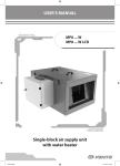
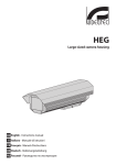
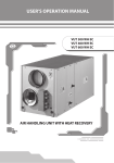
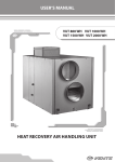
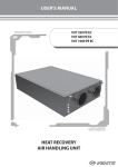
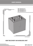
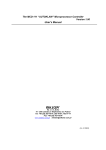
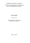
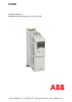
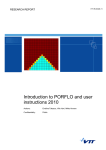
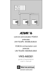
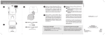
Operation Manual
PA 01W
PA 02W
PA 03W
PA 04W
Automatic Control System for Air Supply Ventilation Unit
with Hydronic Coil Heat Exchanger
2
PA W
Contents
General description
Technical Specifications
Safety Requirements
Functional Diagram
ACS DESIGN AND OPERATION
Safety Precautions
Controller Function Set
Remote control
External Connections Diagram
General Operation Guidelines
Transportation and Storage
Safety Precautions
Manufacturer’s Warranty
Acceptance Certificate
Connection Certificate
Warranty Card
3
4
4
5
5
7
10
14
15
18
18
19
19
20
20
20
3
GENERAL DESCRIPTION
The present technical specification is intended for technicians and engineers involved in design,
installation and setup of ventilation equipment automation systems.
The General Operation Guidelines (see. Page 18) are intended for end users.
Following the control unit operation and maintenance instructions is a prerequisite of its troublefree operation and long service life.
The automatic control system (Fig. 1) is designed for integrated management and control of
ventilation and air conditioning systems.
The device is enclosed in a plastic casing.
The control unit casing contains automatic equipment circuitry of the as well as control and
protective elements of the power components.
The regulating functionality is implemented by means of a programmable controller. The control
unit is suitable for indoor installation in a dust-free dry environment free from chemical contaminants.
The control unit casing meets IP65 standard (units PA 01 W, PA 02 W and PA 03 W) and IP54
standard (unit PA 04 W) with the top lid closed.
The permissible ambient temperature during operation is from +5 °С to +40 °С.
TE5
TE1
P1
PD1
Control Unit
PD1 - pressure safety switch.
P1 - remote control.
TE1 - ambient temperature sensor.
TE5 - supply air temperature sensor.
Fig. 1
The electronic ACS automatic control and monitoring unit performs a number of functions
- in particular:
1.
Switching the unit electric motor on and off.
2.
Selecting the fan speed (3 settings).
3.
Air supply fan operation control and monitoring.
4.
Maintaining the supply air temperature at the pre-set level by actuating the three-way
valve which adjusts the heat-transfer medium delivery into the heating coils.
5.
Protecting the hydronic coil heater against freezing (using the input data from the
downstream air temperature and return water temperature sensors).
6.
Monitoring and control over the operation of the circulation pump delivering the heat
transfer agent to the heating coils.
4
PA W
7. Control of the air cooler compressor and condenser unit (CCU) using the pre-set
temperature.
8.
Filter contamination control.
9.
Control of of the external air damper electric actuator;
10. System shutdown on command from the fire alarm panel.
TECHNICAL SPECIFICATIONS
The main technical specifications are given in Table 1.
Table 1
PA 01W
PA 02W
PA 03W
Supply Voltage, V / 50 Hz
1~230
Operating Voltage of Plugged-in Electric Motor, V
3~230
PA 04W
Motor Power Consumption (max.), kW
0,75
1,1
1,5
2,2
Motor Current Consumption (max.), A
3,5
5,5
7,5
10
340
340
340
500
Width
280
280
280
400
Depth
135
135
135
250
Dimensions, mm
Control Unit Dimensions,
mm
Height
Weight, kg
Рабочая температура окружающего воздуха, °С
Not more than 6
from +5 to +40
Permissible Relative Humidity, %
Protection class (top lid closed)
Not
more
than 11
80
IP65
IP54
SAFETY REQUIREMENTS
Installation and operation of the automatic equipment shall be subject to the present User’s
Operation Manual, «Electrical Installations Code», «Regulations for Customer’s Electric Installations
Operation», the current construction norms and regulations, and the provisions of «Fire Safety
Regulations in Ukraine».
ATTENTION!
The Automatic Control System is to be connected by duly qualified technicians with
appropriate work permits.
Disconnect the automatic equipment from the power mains prior to any installation,
maintenance, connection and repair work.
•
RESTRICTIONS
Do not operate the Automatic Control System outside the permissible temperature
range specified in the User’s Operation Manual or in areas with aggressive admixtures
in the air and in explosive environments.
5
FUNCTIONAL DIAGRAM
Indoors
Outdoors
CCU
Digital Input
Digital Output
Analogue Input
Analogue Output
Design.
Designation
ATV1
Frequency Transformer.
DD1
Pump dry running relay.
PD1
Pressure safety switch on supply air filter.
F1
Supply air filter.
M1
Supply fan.
M2
Circulation Pump.
P1
Control panel.
Q1
Hydronic Coil Heat Exchanger.
Q2
Freon chiller.
SM1
Supply air damper actuator.
SM2
Three-way valve actuator.
TE1
Ambient temperature sensor.
TE3
Return water temperature sensor.
TE4
Heat exchanger freezing protection sensor.
TE5
Supply air temperature sensor.
Fig. 2
AUTOMATIC CONTROL SYSTEM (ACS) DESIGN AND OPERATION
The ACS operates in two modes: «Heating» or «Cooling». The «Heating» or «Cooling» mode is
selected automatically according to the outdoor temperature. if the outdoor temperature is in excess
of Тперех. parameter value (as set from the controller menu, Тперех. parameter (see Table 2), factory
setting +5°С) the system runs in the «Cooling» mode whereas on temperature dropping below the
Тперех. threshold value the system switches to the «Heating» mode.
The fans are started and shut down using button (1) (see Fig. 10) on the control panel.
The air flow (fan speed) is set by button (3) also located on the control panel (see Fig. 10)
The controller activates and deactivates the water coil circulation pump, controls the heattransfer medium valve and opens and closes the ambient air damper automatically.
In the «Cooling» mode the ACS additionally performs the following functions:
When the fan is on the ACS maintains the supply air temperature at the pre-set level (set
from the control panel) by actuating the water coil valve;
On fan shutdown the ACS shuts off the water coil valve and closes the supply and exhaust
air valves.
6
PA W
In the «Heating» mode the ACS additionally performs the following functions:
when the fan is on the ACS maintains the supply air temperature at the pre-set level (set from
the control panel) by actuating the water coil valve;
on fan activation command the ACS warms-up the water coils for n minutes (Warm-up Time
parameter set from the controller menu (see Table 2), factory setting 180 s)prior to the fan
start by means of complete opening the water coil valve.
when the fan is off the ACS maintains the return water temperature downstream of the water
coils at the pre-set minimum level of +20°С.
In both «Heating» and «Cooling» modes ACS protects the water coils against freezing (using the
input data from the air duct thermostat sownstream of the water coils).
If freezing is imminent the control system automatically shuts down the fans, closes the ambient
supply air damper, opens the water coil valve completely and activates the circulation pump.
Circulation Pump Operation.
In the ACS «Heating» or «Cooling» mode the circulation pump activates automatically while the
fans are on or on water coil warm-up initialization and deactivates on fan switching off.
While on standby the circulation pump activates on freezing danger detection irrespective of the
ACS mode.
When freezing is no longer imminent and upon emergency reset the circulation pump reverts to
the pre-emergency state - i.e. continues operation or goes on standby.
In either of the modes the circulation pump will not activate if the heattransfer medium pressure relay DD1 contacts are open. The pressure relay protects the
circulation pump against «dry» running. If the water coil circuit is not equipped with
pressure relay DD1 install a jumper wire on contacts 11-12 (see Fig. 11) and 14-15 (see
Fig. 11) to enable the circulation pump operation. Circulation pump protection may not
be guaranteed without a pressure relay.
Compressor and Condenser Unit Operation
To enable the CCU operation install the unit control panel (see Fig. 10) on the serviced premises.
To activate the cooling mode change the setting on the control panel using button 2 (see Fig. 10)
as confirmed by * symbol on the control panel screen. The ACS switches to cooling automatically on
ambient temperature exceeding +20 0C .
In this mode the water valve is completely closed. The air cooler compressor and condenser unit
(CCU) is activated on room temperature exceeding the pre-set value.
The CCU deactivates on room temperature reverting to the pre-set value. To prevent CCU
overloading due to frequent activation/deactivation there is 600 s interval between the CCU shutdown
and subsequent activation (Min. Act. Time parameter set from the controller menu, see Table 2).
7
SAFETY PRECAUTIONS
The control unit is not intended for operation in environments containing a high concentration of dust,
moisture, explosive and aggressive admixtures etc. If the automatic control system is supplied separately
from ventilation equipment its installation must enable convenient access by maintenance personnel
and easy connection of cables. The mounting surface must be even. The control unit installation must
ensure sufficient space for preventive maintenance and service. Prior to installation check the package for
completeness against the bill of lading and make sure that the contents are intact.
Control unit installation:
While choosing the automatic control system installation site refer to the design
documentation and technical regulations.
Check the installation site for control unit mounting and attachment readiness and ensure
availability of piping and electrical wires at the intended control unit site as well as their proper
marking according to the design documentation.
Install and secure the control unit and make sure it is properly grounded.
Install and secure the external sensors and instruments. Connect the wires to the control
unit terminal blocks in accordance with the external connections diagram (see Fig. 11 and 12).
Control System Sensor Layout.
Supply air temperature sensor TE5 must be installed downstream of the water coils or air cooler
at all times to ensure proper regulation and prevent its freezing. The sensor is intended for measuring
the supply air temperature and, therefore, may not be installed indoors.
Heat exchanger freezing protection sensor TE3 (measuring the return water temperature) must
be installed in the return water pipe in such a way so as to ensure its sufficient contact with the return
water (see Fig. 3).
The heating water circuit must ensure all the required functions specific to the hydronic coil
heater control and safety (in addition to maintaining the proper hot water temperature and flow or
antifreeze filling to the proper level) according to the specifications contained in the air handling
equipment design documentation.
Heat exchanger freezing protection sensor. TE4 (measuring the return water temperature
downstream of the hydronic water coil heater) must be installed directly on the hydronic water coil
heater surface on the hot air exhaust side (see Fig. 3).
Direct Flow Connection
Counterflow Connection
Thermal Converter
Thermal Converter
Wat
er -
Thermal Converter
Fig. 3
Wa
ter
-
Ou
t
Wa
ter
-
In
Thermal Converter
Wat
er -
Ou
In
t
8
PA W
Heat transfer medium connection to the hydronic water coil heater is shown on Fig. 4.
2
1
Mixing Unit Diagram
3
4
6
2
1.
2.
3.
4.
5.
6.
7.
8.
Hydronic Coil Heat Exchanger.
Shutoff Ball Valves.
Circulation Pump.
Flow Control Bypass Valve.
Boiler.
Three-Way Motorized Valve.
Check Valve.
Coarse Filter.
M
7
5
8
.
Three-Way Valve Actuator
Fig. 4
Outdoor Temperature Sensor TE1.
Sensor ТЕ1 should be placed in the ambient environment to ensure its accurate readings while
the system is off or immediately upon its activation (i.e. sufficient heat exchanger warm-up relative
to the actual ambient temperature etc.). If the sensor is mounted in the supply air duct the measured
temperature will only be true when the fan is on.
Supply Air Temperature Sensor TE5.
Supply air temperature sensor TE5 enables temperature regulation and must ne installed
downstream of the water coils or air cooler (relative to the air stream direction). The sensor is intended
for air supply air temperature measurement and, therefore, may not be installed indoors.
ATTENTION!
Incorrect installation of sensor TE1 may distort the measurements and adversely
affect the start-up conditions which, in turn, may cause the hydronic coil heater failure.
Fig. 5
Pressure Safety Switch on Filter PD1.
The pressure safety switch should be installed on the
filter in such a way that the negative input (-) of the relay is
placed in the lower pressure area (i.e. upstream of the filter)
by means of a tube whereas the positive input (+) - in the
higher pressure are (i.e. downstream of the filter) as shown
on Fig. 5.
The maximum pressure drop value set on the pressure
safety switch must correspond to the maximum pressure
drop value on a contaminated filter (please refer to the
ventilation equipment manufacturer’s recommendations).
9
Wall-Mounted Control Panel Р1.
To ensure correct control panel
operation on the premises select a place
where the temperature remains as stable
as possible for the given area and which
does not suffer from a temperature impact
produced by heating radiators, convective
vertical temperature distribution etc. (see
Fig. 6).
Fig. 6
Electronic Control Unit.
The air supply and exhaust unit is equipped with an integrated electronic control unit (see Fig. 7).
PA 01W, PA 02W, PA 03W
TR1 K1
PА 04W
F1 F2
X1
TR1 K1
Z1
Гермовводы
ATV1
Q1
X1
Z1
F1
F2
F1 — fuse
F2 — fuse
К1 — electromagnetic CCU control relay
TR1 — 230VАС/24 VАС transformer
Х1 — terminal box for external leads
Z1 — digital microcontroller
Fig. 7
ATV1 — frequency transformer
F1 — fuse
F2 — fuse
К1 — electromagnetic CCU control relay
TR1 — 230VАС/24 VАС transformer
Х1 — terminal box for external leads
Z1 — digital controller
10
PA W
CONTROLLER FUNCTION SET
Indicator
Left
Right
Fig. 8
The digital controller is the principal control unit component (Fig. 8).
The digital controller has the following controls and indicators:
Indicator
Buttons
LEDs
Indicator — backlit LCD indicator. The indicator displays the current system operation parameters,
temperature, parameter settings and alarms;
Buttons — the digital controller has 6 buttons with the following functions:
ESC — to navigate one level up through the circular list tree (see «Controller Circular List Tree
Menu») or to cancel parameter editing.
Enter — to navigate one level down through the circular list tree (see «»Controller Circular List
Tree Menu»»);
LEFT — to navigate left through the function list; to decrease the parameter being edited.
RIGHT — to navigate right through the function list; to increase the parameter being edited.
F1 — to enter the controller menu.
F2 — to enter the factory controller settings.
11
The main menu as displayed on the indicator screen contains the following icons (Fig. 9):
1 - Current temperature display menu;
2 - Temperature setting;
3 - Current system state;
4 - Service settings menu;
5 - Malfunction signal (displayed when a
malfunction occurs);
6 - Fan state display;
7 - Current supply air temperature display.
Fig. 9
To call the necessary function:
Enter the controller menu by pressing F1. Use LEFT and RIGHT buttons to select the necessary
parameter and press Enter. To go back to the main function list keep pressing Esc until you return to the
main function list.
To change a parameter value:
Select the necessary parameter using LEFT and RIGHT buttons and then press Enter. You can
decrease or increase the value using LEFT or RIGHT buttons correspondingly. The parameter value will
flash. To save the new value press Enter. To leave the menu and cancel parameter changes press Esc. The
modifiable parameter values are framed.
ATTENTION!
The service settings of the controller are programmed at the factory. Any
modifications to these settings must be made by qualified experts using the
«Service Settings Menu» (password-protected). Changing other parameters does
not require a service password.
The controller menu tree is described in Table. 2. The “Factory Setting” column contains the
factory parameters.
Table. 2
Menu Tree
Factory Setting
Purpose of Functions and Parameters, Their Effect
Current Temperature Measurement Display Menu.
TE1
Fresh Air Temperature.
TE3
Return water temperature.
TE4
Air Temperature Downstream of Calorifier.
TE5
Supply air temperature.
Hardware Status and Current Modes Menu.
12
PA W
Heater
Current Heater Power Output (percent).
Pump
Circulation Pump Activation/Deactivation.
CCU
CCU Activation/Deactivation.
Heating/
Cooling
System Operation Mode.
Temperature Setting Menu.
50
Return water temperature at the end of warm-up (in °С). If the return
water temperature at the end of warm-up is lower than the Tret.
warmup value the fan start is blocked and an emergency signal is
generated (see Alarms, alarm, Underheating).
Tret.danger
15
The minimum return water temperature to identify the coil unit
freezing danger (in °С). If the return water temperature falls below
the minimum threshold value (in the «Heating» mode) the water coil
freezing protection is initiated (see Alarms, alarm, Water Alarms).
Тswitch.
0
The ambient temperature in excess of which the ACS switches to
«Cooling» mode.
Tret.warmup
System Malfunction Codes.
E1
The fan shuts down in case of an interruption or shorting in the
ambient air temperature sensor circuit.
E2
The fan shuts down in case of an interruption or shortening in the
circuit of exhaust air temperature sensor downstream of the thermal
wheel.
E3
The fan shuts down in case of an interruption or shortening in the
circuit of the return water temperature sensor.
E5
The fan shuts down in case of an interruption or shortening in the
circuit of supply air temperature sensor.
U1
Alarm U1 (water coils freezing danger) is generated if the water
temperature downstream of the water coils falls below the pre-set
critical value causing the fan to shut down.
U2
Alarm U2 (low return water temperature downstream of the
water heating coils) is generated if the return water temperature
downstream of the water heating coils falls below the pre-set critical
value. In case of any of the alarms due to imminent freezing the
fan shuts down, the water coil valve is set to 100% open and the
circulation pump is started. It should be noted that the fans cannot be
started while any of the alarms due to imminent freezing is active.
The system can be restarted only when the water coil freezing danger
is no longer imminent - i.e. after the return water temperature ТЕ3 (for
Alarm U2) and air temperature downstream of the water coils ТЕ4 (for
Alarm U1) raises over the threshold value set to prevent the water coils
against freezing.
13
U3
Alarm U3 (Underheating) is generated if while in the «»Heating»»
mode at the end of the water coils warm-up cycle (preceding
the fan start) the return water temperature downstream of the water
heating coils remains below the pre-set value (factory setting - 50°С).
This alarm will prevent the fans from starting.
U4
Alarm U4 (pump failure) is generated if the water coils line pressure
relay generates no signal on the air coils start command. In case of this
alarm the water coil pump is disabled. However, this has no effect on
the fan status - i.e. if the pump fails the fan may continue operation if
previously on.
P1
Supply fan failure causes fan shutdown.
P2
Exhaust fan failure causes fan shutdown.
O1
Emergency system shutdown on command from the fire alarm panel
causes fan shutdown.
TM
Alarm – emergency shutdown while in the scheduled (weekly timer)
mode. This alarm is generated if the ventilation system is manually
shut down using «STOP» button on the control unit front panel during
the scheduled fan operation.
F1
Filter Alarm. This alarm is generated on closure of the pressure safety
switch installed on the fresh air filter.
Service Settings Menu.
Settings Menu. This menu contains the basic settings of the controller. Any modifications to these settings must
be made by qualified experts. Failure to do so may cause controller malfunction or faulty operation. Therefore,
the settings menu is password-protected. The password shall be only disclosed to service engineers responsible
for the system to avoid unauthorized changes of the controller settings.
Settings menu password («2222» by default). The password consists of 4 characters displayed in asterisks (****)
Use LEFT and RIGHT buttons to enter the first number of the password and then press ENTER. Then use the LEFT
and RIGHT buttons to enter the second digit followed by pressing ENTER, then repeat for the remaining digits.
To re-enter the previous password digit press RETURN. On entering the 4th password digit (if entered correctly)
the system will automatically switch to the settings menu. The indicator screen will show «Service Menu».
Heater
Heater Settings Menu
Heater->
Control Settings
This menu enables setting the water coils valve control pattern.
Heater ->
Control Settings
-> Кр
2
PI control proportion factor.
Heater ->
Control Settings
-> Ti
60
PI integration constant (in seconds).
14
PA W
Heater ->
Control
Settings ->
Deadband.
0,5
Heater ->
Protection
Settings
Heater ->
Protection
Settings ->
Warm-up Time
Heater Protection Settings Menu.
180
Cooler
Cooler ->
MinTime. On.
Deadband.
Water coils warm-up time (in seconds). During the warm up the water
coil valve is set to 100% open while the «Warm-Up/Alarm» indicator
flashes.
Cooler Settings Menu.
600
Fan
CCU minimum activation time.
Fan Settings Menu.
Fan -> Start
Timeout
30
Pump
The pre-set fan failure analysis time (in seconds). This is the timeout
of the fan start command given for the corresponding fan frequency
converter to respond whereas no response generates a supply or
exhaust alarm (see Alarms).
Pump Settings Menu.
Pump ->
MinOpTime.
20
Pump ->
Cooling
Operation
Enabled
The minimum time of the circulation pump operation (in seconds).
This parameter enables circulation pump operation in the «Cooling»
mode. Two values are possible: Disabled — pump operation in the
«Cooling» mode is disabled; Enabled - the pump will activate with the
water coils valve in the «Cooling» mode.
Any of the alarms listed in the table is signaled by the indicator
and the alarm
code shown on the screen. The system alarm response is described in Table 2. The
controller has the automatic alarm reset function on system re-start from a remote
control provided the elimination of the alarm cause.
REMOTE CONTROL
The air supply and exhaust unit is equipped with a remote control enabling:
Switching the air handling unit on/off.
Setting the necessary air flow rate.
Setting the desired supply air temperature.
Room temperature indication.
Day/Night mode activation/deactivation.
15
Fig. 10
1.
2.
3.
4.
5.
6.
7.
8.
9.
10.
11.
12.
13.
14.
ON button;
Heating/Cooling mode switch;
Fan speed selector (auto/high/med/low);
Day/Night mode;
Supply air temperature button (temperature up);
Supply air temperature button (temperature down);
Output temperature signal indicator;
Output temperature signal value;
Supply air temperature setting indication;
Temperature unit;
Day/Night mode indication;
Selected fan speed indication;
Mode indication: Heating or Cooling;
Room temperature indication.
The system is switched on or off using button (1), Fig. 10. The air flow rate (LOW, MED, HIGH or
AUTO) is cycled by pressing button (3), see Fig. 10, while the current speed setting is shown on the
remote control screen. The Day/Night mode is selected by pressing button (4). To switch the system
from the «Day» mode to the «Night» mode press button (4) and hold it for 3 s. The selected mode
is shown on the remote control screen (11). The supply air temperature can be set as desired using
buttons (5) and (6) whereas the current temperature setting shows on the remote control screen (9).
The «Heating» or «Cooling» modes are cycled by pressing button (2) as shown on the remote control
screen (13).
EXTERNAL CONNECTIONS DIAGRAM
Disconnect the unit from the power supply prior to any electric work. The power mains connection
shall only be performed by a professional electrician. The nominal electrical parameters of the unit are
given on the manufacturer’s label. Any tampering with the internal connections is prohibited and will
void the warranty. The unit takes 230V/50 Hz single-phase alternating current.
The connection must be made using durable, insulated and heat-resistant conductors (cables and
wires) with the minimum section of 2,5 mm2.
The given wire sections are for reference only. The conductor section selection shall account for
the maximum permissible wire heating which depends on the wire type, its insulation, length and
installation method (i.e. overhead, in pipes or inside the walls). The unit connection shall be made
on terminal block X1 mounted inside the control unit (see Fig. 7) in accordance with the external
connections diagram and terminal designations as shown on Fig. 11 (for PA 01W, PA 02W and PA 03W
units) or on Fig. 12 (for PA 04W unit) according to the air handling unit type.
DO6 DI6
DI7
∼
24V AC
AO3
AI7
DI2
AI6
D010
DIgnd
DI8
AI1
AIgnd
AI3
AIgnd
AI4
AI5
DIgnd
DI4
AOgnd
AO1
Freemax MX
DO9
Power Input 230 V AC
2
PE
3x2,5 mm
PE
PE
M2*
PE N
N
L
L
M1
W2 V2 U2 U1 V1 W1 PE ТК ТК
V W U PE
L N PE
N
ATV1.1
L
2
L
SM1*
N
1 2
1
N
2
2x1 мм
L
2
DD1*
1
1
2
PK1*
2 1
1
1
3
+
SM2*
-
Y
1
1
2
6
6
11
10
12 11 10
12
14
4
9 14 13 4
9
5
5
Р1
SAS908PIT-V2-S1-F3
2
- ELECTRIC SHOCK HAZARD!!!
U
1 2 3 5
2
3
PD1
2
3
1
1
1
TE3
TE4
1 2
2
1 2
1
1 2
2
TE1
1
2 1
nc
TE5
1
no
1
1
2
2
ATV1.2
3 4 с no nc
3
1. The system may operate without the water pressure relay in calorifier DD1 in which case contacts 1 and 11
must be closed with a jumper.
2. The cable from the remote control (Р1) shall not exceed 10 m in length.
3. *- The devices are supplied separately.
Сигнал включения ККБ
(NO)
N
tÅ
L
L N PE 1 2 3 4 5 6 7 8 9 10 11 12 13 14 15 16 17 18 19 20 21 22 23 24 25 26 27 28 29 30 31 32 33 34 35 36 37 38 39
DO7
DI3
tÅ
tÅ
X1
DO5
DI1
tÅ
Fig. 11
DIgnd
External Connections Diagram for PA 01W, PA 02W and PA 03W Units
16
PA W
DO7
DO6 DI6
DI7
∼
24V AC
AO3
AI7
DI1
DI2
DI3
AI6
DIgnd
DI8
AI1
AIgnd
AI3
AIgnd
AI4
AI5
Freemax MX
2
V
W
U
PE
TK
TK
PE
N
M1
W2 V2 U2 U1 V1 W1 PE ТК ТК
L
L
2
L
SM1*
N
1 2
1
Power Input 230 V AC
N
L
DD1*
1
1
2
2 1
1
PK1*
2
3
-
+
U
1
1
2
6
6
11
10
12 11 10
12
14
4
9 14 13 4
9
5
5
Р1
SAS908PIT-V2-S1-F3
2
- ELECTRIC SHOCK HAZARD!!!
Y
1 2 3 5
2
SM2*
1
1
3
PD1
2
3
1
1
1
TE1
TE3
TE4
TE5
2 1
1
1 2
2
1 2
1
1 2
2
1. The system may operate without the water pressure relay in calorifier DD1 in which case contacts 14 and 15
must be closed with a jumper.
2. The cable from the remote control (Р1) shall not exceed 10 m in length.
3. *- The devices are supplied separately.
M2*
1 2 3 4 5 6 7 8 9 10 PE N
X2
3x2,5 mm
2
2x1 мм
Сигнал включения
ККБ (NO)
PE
tÅ
N
tÅ
L
L N PE 1 2 3 4 5 6 7 8 9 10 11 12 13 14 15 16 17 18 19 20 21 22 23 24 25 26 27 28 29 30 31 32 33 34 35 36 37
DO5
D010
tÅ
X1
U V W PE
ATV1
L1 L2 PE
DIgnd
DIgnd
tÅ
Fig. 12
DI5
External Connections Diagram for PA 04W Unit
17
18
PA W
Design.
Name
ATV1
Frequency Transformer
DD1*
Pump Dry Running Protection Relay
PD1
Pressure safety switch on fresh air filter
M1
Supply Fan
M2*
Circulation pump
P1
PK1*
Type
Depends on motor
type
NO
2x0.75
DTV500
2x0.75
Depends on unit
type
max. 0,3 kW
3x0.75
NO
2x0.75
Remote control
Fire alarm panel lead-in
SM1*
Supply air damper actuator
SM2*
Three-way valve actuator
Recommended Cable
Sections*
8x0.2
LF 230 Belimo
2x0.75
LR 24 SR Belimo
3x0.75
ST-01
2x0.75
TE1
Ambient temperature sensor
TE3
Return water temperature sensor
STw-02
2x0.75
TE4
Water coil freezing protection sensor
STw-02
2x0.75
TE5
Supply air temperature sensor
Sta-02.l
2x0.75
The cables are routed into the terminal box through a sealed lead-in on control unit side wall to
ensure protection class compliance (see Fig. 7). The external lead-in (230V/50Hz) must be equipped
with an automatic cutout switch with a magnetic breaker built into the stationary wiring to disconnect
the power voltage. The external switch location must ensure free access for quick shutdown of the
unit. The trip current shall be consistent with the current consumption of the unit.
GENERAL OPERATION GUIDELINES
The operation, technical maintenance and repair shall be performed only by qualified
experts familiar with the present document.
Unpack the control unit carefully, perform a visual inspection and check for mechanical
damage.
Check the package for completeness. After transportation under temperatures below zero
the automatic unit shall be kept unpacked in normal conditions for 24 hours.
While making connections and installing equipment follow the instructions in the
present User’s Operation Manual.
The system will operate normally only provided a 24-hour uninterrupted power supply.
TRANSPIRATION AND STORAGE
The control unit must be handled as fragile goods.
The control units must be stored in premises where:
- the maximum relative humidity does not exceed 85 % and the conditions prevent moisture
condensation
- the ambient temperature is within the range from –25 °C to +60 °C.
The equipment storage methods must prevent ingress of dust, water, caustic or other
corrosive substances or adversely affecting the structural parts and elements (reduce the strength of
plastic insulation parts etc.).
19
SAFETY PRECAUTIONS
The system maintenance shall be performed by electricians with the minimum electrical
safety qualification Level 3 (electrical installations with a voltage of up to 1000 V).
The system and its peripheral equipment service shall be performed pursuant to the Safety
Requirements in the Electrical Installations Code (PUE) and Safety Regulations (PTB).
All the adjustments performed on energized equipment must be performed by at least 2
persons.
The control unit is compliant with the Electrical Installations Code (PUE).
The control unit is classified as follows:
rank 3 in terms of operational completeness;
in terms of metrological properties the unit is classified as a measuring instrument only
insofar as the built-in measurement instrumentation is concerned;
in terms of ingress protection the unit design offers no special protection against the
elements;
in terms of mechanical stress resistance the control unit is rated vibration-proof «L3».
The control unit is:
susceptible to seismic activity;
insensitive to static or alternating magnetic fields of power grid frequency at voltages up
to 400 A/m;
resistant to admissible industrial radio interference;
the characteristic properties are given with respect to electric insulation of the power
circuits and insulation of circuits with different nominal voltages.
MANUFACTURER’S WARRANTY
Manufacturer hereby guarantees normal performance of the unit during two years from the date of
retail sale provided compliance with transport, storage, mounting and operation regulations.
In case of no confirmation of the sales date the warranty period is calculated from the manufacturing
date. In case of failures in the unit operation during the warranty period the manufacturer will accept
reclamations and complaints from the owner of the device only after receiving technically sound act
with detailed description of the failure. Unit damage as a result of unauthorized tampering with the
circuit diagram is not a warranty case. For warranty and post-warranty services of the unit please contact
the product manufacturer. In case of warranty claim please submit the present user’s manual with the
seller’s stamp, filled connection certificate and warranty card. Warranty repair services (provided that
the warranty card and the seller’s stamp and the present user’s manual) and post-warranty services
are fulfilled at the manufacturing facility. If returning the device under warranty please show this
User’s Operation Manual, the duly filled-in Connection Certificate and the Warranty Card. Fulfill the
requirements set in the user’s manual to ensure proper functioning of the unit.
WARRANTY CLAIMS ARE ACCEPTED WITH THIS USER’S MANUAL AND FILLED
CONNECTION CERTIFICATE ONLY.
The MANUFACTURER is not responsible for any mechanical or physical damages
resulting from the manual requirements violence, the unit misuse or gross mechanical
effect.
The unit owner must follow the applicable instructions.
20
PA W
ACCEPTANCE CERTIFICATE
The PA W air supply system control unit is compliant with the Electrical Installations Code (PUE)
and is hereby declared ready for service.
Acceptance Inspector’s Stamp
Date of manufacture ____________________
Sold by
Name of trade company _______________________________________________________________
___________________________________________________________________________________
Date of sale_____________________________
ELECTRICAL CONNECTION CERTIFICATE
This is to certify that the PA W has been connected to power mains pursuant to the requirements
stated in the present user’s manual by a qualified technician:
Company___________________________________________________________________________
Name______________________________________________________________________________
Date_________________________Signature_______________________________________________
___________________________________________________________________________________
WARRANTY CARD
21
22
PA W
23
2012
V43(automatic)ENG-06