1
Quad-Relay Delay Switch (QRDS)
User Manual (v1.0)
Introduction:
The QRDS-1000 Quad-Relay Delay Switch provides general purpose control for up to four independent
devices. It also offers optional activation and deactivation delays via configurable onboard DIP switches.
The product provides four (4) wired control inputs and is operated standalone without the need for a host
PC. The following control methods are provided:
• External switch closures
• Discrete TTL inputs
The product is useful in a variety of applications including the following:
•
•
•
•
•
•
•
•
Security
Access control
Automation
Industrial control
HVAC
Lighting
Pumps
Robotics
Features:
The product has the following features:
•
•
•
•
•
•
•
•
•
•
Four (4) form-C relays with N/C, N/O, and COM contacts (see not below)
Four (4) wired control inputs (accept switch closure or TTL signal)
LED indicators for visual relay activation status
Configurable activation delay (1 to 3 minutes)
Optional deactivation delay (1 to 3 minutes)
Configurable external switch type (normally-open, normally-closed)
Accepts optional digital pulse input
Piezo buzzer for audible alert (enabled via DIP switch)
Accepts optional AC adapter (12VDC)
Optional slimline enclosure with mounting flange
Hardware Overview:
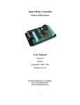
The QRDS-1000 features a printed-circuit board with digital microcontroller and required peripherals. The
microcontroller continuously monitors the four switch inputs and provides relay activation control with
specified relays. The following photo depicts key elements of the device:
Power Source:
The QRDS-1000 accepts an input voltage range of 7 to 25VDC which may be provided at TB-5 screw
terminals 1 & 2. In addition, an onboard barrel jack is provided for use with compatible AC adapter.
(Inner pin is positive polarity. Recommended plug dimensions: 2.1mm I.D., 5.5mm O.D.)
Note: Power should be applied at either the screw terminals or the barrel plug - never both at once.
Operation:
A relay is activated by trigger input due to external switch action (e.g., switch closure). Either normallyopen or normally-closed switches may be used. (Refer to section, Configuration DIP Switches for details.)
If an optional activation delay has been configured, the relay will not engage until the delay expires. If
the trigger input returns to its pre-activation state before that time (e.g., switch opens), the pending
activation will be cancelled and the delay timer will be reset.
Once activated, the relay remains engaged until the trigger condition has cleared (i.e., external switch
opens or TTL signal returns high). If optional deactivation delay has been enabled, the relay will remain
engaged until the delay expires. (The deactivation delay will be the same duration as the configured
activation delay.)
Notes: 1) Triggers may also be optionally initiated by TTL signal.
2) Do not use lighted doorbell switches or similar devices since current may leak through the
bulb, resulting in inadvertent activation.)
Indicators:
There are five onboard LED indicators as desbribed below:
• Green LED
This LED is a system status indicator (slow blinking = firmware is active)
• Solid - activated
• Fast blinking = pending activation
• Red LEDs
There are four (4) red LEDs which provide an indication of relay activation status as follows:
• Off - No activation, no trigger condition
• Solid - relay activated
• Fast blinking - trigger condition present, relay activation is pending (following prescribed delay)
Note: If an activation is pending, the trigger condition must remain active for the entire duration of the
delay period. Otherwise, the activation will be cancelled and the timer will be reset.
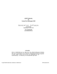
Configuration DIP Switches:
The QRDS-1000 contains six (6) available configuration DIP switches. The individual switch assignments
are identified in the photo below:
Switches may be adjusted using a miniature screwdriver or similar implement. Available parameter
settings are listed below:
•
•
•
•
•
Relay Activation Delay
Relay Deactivation Delay
Piezo Beeper Enable
Pulse Input Enable
Input Trigger State
Notes: 1) The device should be powered off prior to making DIP switch setting adjustments.
2) Use caution when adjusting settings to avoid damaging individual switches.
Parameter settings are described in detail below:
•
Relay Activation Delay:
An optional activation delay may be configured using onboard DIP switches 1 & 2. Activation
delay defines the amount of time that the trigger input must remain enabled before the relay will
engage. (A delay of "0" implies no activation delay and will cause the relay to enage
immediately.)
This delay will be invoked when any trigger input becomes active and effectively postpones relay
engagement for the specified period of time. (The trigger must remain active for the entire time
period. Otherwise, relay engagement will be cancelled.)
To configure the activation delay, set the DIP switches up or down according to listing below:
Activation
Delay
----0 (none)
1 min.
2 min.
3 min.
•
Sw. 1-2
------Up - Up
Dn - Up
Up - Dn
Dn - Dn
Relay Deactivation Delay:
An optional deactivation delay may be specified in conjunction with the activation delay described
above. The deactivation delay is configured using onboard DIP switch 3. This delay will be invoked
following a relay activation and will keep the relay engaged for a period of time after the trigger
input becomes disabled (high). The period of time that the relay will remain engaged is equal to
the activation delay described above (configured at switches 1 & 2).
For example, a configured activation delay of 2 minutes will result in a deactivation of the same
duration. (If there is no activation delay (i.e., "0"), then there will be no deactivation delay, even
if enabled at the DIP switch.) To enable deactivation delay, set the DIP switch as shown below:
Deactivation
Delay
----Enabled
Disabled
Sw. 3
----Dn
Up
Note: A switch in the down ("Dn") position designates enabled while the up position denotes
disabled.
•
Piezo Beeper Enable:
An onboard piezo beeper (if installed) provides audible annunciation when a relay activation
occurs. To enable the piezo, set the applicable DIP switch listed below:
Beeper
----Enabled
Disabled
Sw. 4
----Dn
Up
Note: A switch in the down position designates "Enabled" while the up position denotes
"Disabled".
•
Pulse Input Enable:
The QRDS-1000 may accept external switch closure or TTL inputs. Some devices may deliver a
pulsed TTL output rather than a constant voltage. Enabling pulse input processing allows the
onboard digital controller to properly interpret this signals for subsequent relay activation. To
enable pulse inputs, set the applicable DIP switch listed below:
Pulse
Input
----Enabled
Disabled
Sw. 5
----Dn
Up
Notes: 1) This setting is applicable to each of the four available wired inputs.
2) Pulsed signals must have a minimum frequency of 1 Hz.
3) A switch in the down position designates "Enabled" while the up position denotes
"Disabled".
•
External Switch Type:
Relay engagement (trigger) will occur following activation of an external input switch. The QRDS1000 can accept the following switch types:
• Normally-open
• Normally-closed
The type you use is likely to be defined by the application. For instance, a home alarm system
might typically use a normally-closed switch at each door or window. These switches would be
wired in series, forming a circuit. If any door or window is breached, the circuit would be opened
causing the relay to sound an alarm and/or activate flood lights. On the other hand, a normallyopen sensor switch might be expected for an automatic sump pump application. The switch closes
when the water level gets too high, causing the relay to activate the pump.
To select the desired switch type, set the applicable DIP switch listed below:
Switch
Type
---Normally-Closed
Normally-Open
Sw. 6
----Dn
Up
Notes: 1) The normally-closed selection requires jumper wires at all unused external switch
inputs. (Jumpers are unnecessary for the normally-open setting.) For example, consider
an application using three (3) normally-closed switches which are wired at external
inputs #1, #2, & #3 (with correponding return wires). Since external input #4 is
unused, a jumper would be applied from this terminal to return #4. (Refer to External
Switch Wiring for details.)
2) For TTL inputs, choose normally-open for active-low signals or normally-closed for
active-high signals. (The normally-closed selection requires jumpers for all unused
external signal inputs as explained in the previous note.)
3) A switch in the down position designates "Normally-closed" while the up position
indicates "Normally-open".
Hardware Installation:
The General Purpose Quad Relay Delay Switch is easily installed:
• Remove the two retaining screws which attach the enclosure lid to its base (if supplied).
• Connect wiring for your equipment under control to relay contacts at terminal blocks TB-1 to TB-4.
(Refer to the Wiring section for details.)
• Connect input control wiring at terminal block TB-5. (Refer to the Wiring section for details.)
• Configure optional delays, piezo-enable, and/or other settings using the onboard DIP switches.
• Mount the unit on a wall or other surface and attach using compatible screws (not included).
• Apply 7 to 12VDC power using compatible AC adapter (500 mA minimum). (Optionally, you may
supply power at TB-5, terminals 1 & 2).
• Re-attach the lid (if supplied).
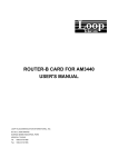
External Switch Wiring:
The QRDS-1000 provides a screw terminal block (TB-5) for wiring up to four (4) external switches. (You
may also interface TTL signals from a microcontroller or other device.) The photo below identifies
applicable terminals:
To wire an external switch, connect it as described below:
Normally-closed:
Switch
Contact
-------N/C
COM
TB-5
Terminal
-------Ext. Input #N
Return #N
Normally-open:
Switch
Contact
-------N/O
COM
TB-5
Terminal
-------Ext. Input #N
Return #N
The complete listing of TB-5 screw terminal definitions is given below:
TB-5: Control inputs:
-------------------1) +12VDC In/Out
2) Ground
3) +5VDC out (100mA max.)
4) Ext. Input 1
5) Gnd-return 1
6) Ext. Input 2
7) Gnd-return 2
8) Ext. Input 3
9) Gnd-return 3
10) Ext. Input 4
11) Gnd-return 4
12) not used
13) not used
14) Ground
Notes: 1) Screw terminal #1 is indicated by a small white square imprinted on the circuit board
beside the connector.
2) External input connections can accept external switch-closure or TTL input.
3) Only a subset of the given terminals will be needed for any given application.
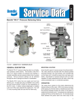
Relay Wiring:
Four (4) terminal block connectors are provided for relay wiring purposes (TB1 through TB4). The photo
below identifies the terminals corresponding to individual relay contacts:
Screw terminal definitions for each of the four relays are listed below:
TB-1: Relay #1 Contacts:
----------------------1) N/C
2) COM
3) N/O
TB-2: Relay #2 Contacts:
----------------------1) N/C
2) COM
3) N/O
TB-3: Relay #3 Contacts:
----------------------1) N/C
2) COM
3) N/O
TB-4: Relay #4 Contacts:
----------------------1) N/C
2) COM
3) N/O
Notes: 1) Screw terminal #1 is denoted by a small white square imprinted on the circuit board
beside the connector.
2) Relays have a specified 10A capacity but board traces limit actual capacity to 5A.
Maintenance:
The product requires no special care or maintenance other than protection from direct exposure to
moisture, power surges, static electricity, weather, and other hazards.
Warranty:
This product is warranted for a period of 90 days from the date of purchase and is guaranteed to be free
from defects. The warranty covers the entire unit, except if any part or component has been modified or
otherwise converted from its original form. The warranty does not cover damage or failure due to
neglect, improper use, or unshielded exposure to the elements.
Note: The customer is responsible to provide protection against static electricity and over-voltage
situations including power surges, spikes, and lightning strikes. The use of a surge protection at the AC
power source is strongly encouraged.
Disclaimer:
Kadtronix and Delahoussaye Consulting shall not be held liable or responsible for incurred damage or
injury which may result due to the use or misuse of this product.
Contact Information
Should you have any questions or comments please contact us at:
Ken Delahoussaye
Senior Engineer / Consultant
Delahoussaye Consulting
http://www.kadtronix.com
[email protected]
321-757-9280