1
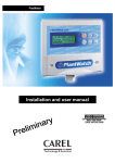
Data Acquisition Software User’s Manual Version 2.1 Triangle BioSystems International 2224 Page Rd. Suite 108 Durham, NC 27703 Phone: (919) 361‐2663 • Fax: (919) 544‐3061 www.trianglebiosystems.com NeuroWare © User’s Manual Contents Document Overview ....................................................................................................................... ‐ 3 ‐ System Overview ............................................................................................................................ ‐ 3 ‐ Standard Shipped items list ............................................................................................................. ‐ 4 ‐ System Requirements ..................................................................................................................... ‐ 4 ‐ System I/O ..................................................................................................................................... ‐ 4 ‐ POWER INPUT ................................................................................................................. ‐ 5 ‐ Analog Input .................................................................................................................... ‐ 5 ‐ DATA A............................................................................................................................ ‐ 5 ‐ DATA B ............................................................................................................................ ‐ 5 ‐ USB A .............................................................................................................................. ‐ 5 ‐ USB B .............................................................................................................................. ‐ 5 ‐ GND ................................................................................................................................ ‐ 5 ‐ DATA I/O ......................................................................................................................... ‐ 5 ‐ Headstage input pinout .................................................................................................... ‐ 5 ‐ NeuroWare © Installation................................................................................................................. ‐ 6 ‐ Loading and Configuration .............................................................................................................. ‐ 8 ‐ Start NeuroWare ................................................................................................................. ‐ 8 ‐ Load a Configuration File...................................................................................................... ‐ 8 ‐ Configure NeuroWare © ........................................................................................................ ‐ 9 ‐ Load New Config.................................................................................................................. ‐ 9 ‐ Save.................................................................................................................................. ‐ 10 ‐ Return to NeuroWare ........................................................................................................ ‐ 10 ‐ Daq tab ............................................................................................................................. ‐ 10 ‐ Spike Tab .......................................................................................................................... ‐ 10 ‐ LFP Tab ............................................................................................................................. ‐ 11 ‐ Notch Filter Tab ................................................................................................................. ‐ 12 ‐ Chart Display Tab............................................................................................................... ‐ 12 ‐ Reference Tab ................................................................................................................... ‐ 12 ‐ Record Data Tab ................................................................................................................ ‐ 12 ‐ Record Data Tab ................................................................................................................ ‐ 13 ‐ Version1.2 ‐1‐ 1/2014 NeuroWare © User’s Manual System Gain Tab ................................................................................................................ ‐ 13 ‐ Start Data Acquisition ................................................................................................................... ‐ 14 ‐ Notch Filter .................................................................................................................................. ‐ 15 ‐ Spike Detection and Display .......................................................................................................... ‐ 17 ‐ Spike Filter ........................................................................................................................ ‐ 17 ‐ Spike Triggering ................................................................................................................. ‐ 18 ‐ Audio Output .................................................................................................................... ‐ 18 ‐ Graph Settings................................................................................................................... ‐ 19 ‐ Auto Trigger Settings ......................................................................................................... ‐ 19 ‐ Threshold Settings ............................................................................................................. ‐ 20 ‐ Spike Channels Tabs...................................................................................................................... ‐ 21 ‐ Strip Chart.................................................................................................................................... ‐ 22 ‐ LFP Waveform .............................................................................................................................. ‐ 23 ‐ Multi‐Channel Viewer ................................................................................................................... ‐ 24 ‐ Channel Reference........................................................................................................................ ‐ 26 ‐ Record Data ................................................................................................................................. ‐ 27 ‐ File Types .......................................................................................................................... ‐ 27 ‐ File Save Path .................................................................................................................... ‐ 28 ‐ Recording Data Selection ................................................................................................... ‐ 28 ‐ Comments......................................................................................................................... ‐ 28 ‐ Recorded Channel ............................................................................................................. ‐ 28 ‐ Recorded File Name........................................................................................................... ‐ 29 ‐ Start/Stop Recording ......................................................................................................... ‐ 30 ‐ How to Load Nex File ......................................................................................................... ‐ 30 ‐ How to Load Text Data....................................................................................................... ‐ 30 ‐ Events.......................................................................................................................................... ‐ 31 ‐ Digital Lines Connection ..................................................................................................... ‐ 31 ‐ Digital Events .................................................................................................................... ‐ 31 ‐ Event File .......................................................................................................................... ‐ 33 ‐ Analog Input Channel.................................................................................................................... ‐ 34 ‐ Error Log Window......................................................................................................................... ‐ 35 ‐ Version1.2 ‐2‐ 1/2014 NeuroWare © User’s Manual Quit NeuroWare ........................................................................................................................... ‐ 35 ‐ Reading files................................................................................................................................. ‐ 36 ‐ Load Data into NeuroExplorer ............................................................................................ ‐ 36 ‐ Load Data into MatLAB ...................................................................................................... ‐ 38 ‐ Technical Support ......................................................................................................................... ‐ 41 ‐ Contact Information.................................................................................................................. ‐ 41 ‐ Version history for this manual...................................................................................................... ‐ 41 ‐ DocumentOverview This document is intended to educa te users about the full functionality of TBSI’s online da ta © a cquisi tion softwa re. NeuroWa re has the capabili ty to graphi call y display and s tore up to 32 simul taneous channels of neural da ta . SystemOverview © NeuroWare is designed to interface s eamlessly with all TBSI tethered and wireless (shown above) neural recording systems. Version1.2 ‐3‐ 1/2014 NeuroWare © User’s Manual StandardShippeditemslist 1 Wi reless headsta ge 1 Magnet on/off wand 1 Wi reless recei ver/demux base s tation 2 recei ver antenna 2 recei ver antenna extension ca bles 2 antenna clamps 1 USB A‐B cable 1 6v power suppl y 1 heads tage cha rger 1 heads tage tes t cable 1 heads tage shorti ng plug SystemRequirements The recommended minimum PC requi rements a re as follows : At leas t i7 Quad Core Processor 8 GB RAM, DDR1333 or higher 512MB of video memory C: dri ve (OS) SATA 2 3GB/S or faster, 250GB or grea ter D: dri ve (s tora ge) SATA 3 6GB/S SSD 500GB or grea ter RECOMMENDED HARDWARE IS A SATA 3 (6GB/S) SAMSUNG EVO SSD 500GB OR LARGER. USB 2.0 port Wi ndows 7 64 bi t OS SystemI/O Version1.2 ‐4‐ 1/2014 NeuroWare © User’s Manual POWERINPUT – This is to be connected to the 6V DC power suppl y provided by TBSI onl y. AnalogInput ‐ TTL i nput, ±5V, 30kS/s . DATAA – Digi tal Events input DATAB – Digi tal Events input USBA – Pri ma ry ADC I/O connection USBB – Seconda ry ADC I/O connection GND – Ea rth ground connecti on lug DATAI/O– Not supported Headstageinputpinout– refer to appropria te channel ha rdwa re manual Version1.2 ‐5‐ 1/2014 NeuroWare © User’s Manual NeuroWare©Installation Install the driver for the USB‐2533 DAQ card Na viga te to CD dri ve:\NeuroWa re\DAQ Dri vers and run mccdaq.exe. Follow the prompts to ins tall the DAQ dri vers and the Insta cal and Tra cerDAQ softwa re tools. You ma y be requi red to resta rt your computer once ins tallation is complete. Install NeuroWare Na viga te to CD dri ve:\NeuroWa re Ins taller\Volume and run the file labeled setup.exe. Follow the prompts to ins tall the NeuroWa re © softwa re. Copy files from Installation CD to PC Copy the TBSI folder on the ins tallation CD to the C:\ dri ve on your PC. Configure the DAQ card’s channel number in Instacal Connect the recei ver to your computer wi th the USB cable. Your computer will detect this as a new devi ce and ins tall additional dri vers automa ti cally. Once the dri vers a re ins talled, you ma y na vi ga te to the Devi ce Mana ger on your computer a nd check to see if “DAS‐COMPONENT‐USB 2533” is included the lis t of a vailable devi ces . Run the newl y installed Instacal progra m. Version1.2 ‐6‐ 1/2014 NeuroWare © User’s Manual In Ins ta cal, you will see Board# 0 ‐ USB‐2533 (serial#******) under Uni versal Serial Bus . (Note: Ea ch DAQ boa rd is assigned a different serial number, but the boa rd number in Ins ta cal should alwa ys be “0”.) If you can’t see a devi ce like this, check the s ys tem’s USB and power connections. Version1.2 ‐7‐ 1/2014 NeuroWare © User’s Manual Ri ght‐cli ck the DAQ boa rd shown in the list, then cli ck Configure. Select 64 Single Ended i n the field for No. of Channels. Cli ck OK to a ccept these changes . You ma y now close the Ins tacal progra m window. A s creen resolution of at least 1280x1024 is recommended to run NeuroWa re©. LoadingandConfiguration StartNeuroWare © You can run NeuroWa re via the Windows Start Menu by na viga ting to Start͢/All Programs/NeuroWare. If there is no ri ght license file named as “NeuroWa re li cence.dat” in C:\TBSI\configure file, NeuroWa re ma y run in demo mode. In demo mode Recording is disabled. LoadaConfigurationFile Upon loadi ng NeuroWa re © for the fi rs t ti me, you will be asked to select a configura tion file. Ea ch configura tion file contains progra m functionality settings for a specifi c TBSI recording devi ce. Version1.2 ‐8‐ 1/2014 NeuroWare © User’s Manual Choose the confi gura tion file which ma tches your da ta a cquisi tion ha rdwa re model (ex. a file ending in M32 should be used wi th a 32 channel M‐Series recording s ys tem). ConfigureNeuroWare© Adjusting Settings in a Configuration File © To change and sa ve selected DAQ settings to be loaded in future ins tances of NeuroWa re , na vi ga te to the Tools menu at the top left of the program, then select Configuration from the drop‐down menu to open the Configuration Dialog. Many settings in the Configura tion Dialog a re unique to tha t menu and can’t be a ccessible in NeuroWare . It is recommended to review all settings in the Confi gura tion Dialog to ensure tha t ea ch pa rameter is appropria tel y defined. Refer to other sections for how to set up those settings tha t a re onl y a ccessible in Configuration. Be sure to s top DAQ before opening the confi gura tion dialog. LoadNewConfig Use this button when you want to load a new configura tion file. Version1.2 ‐9‐ 1/2014 NeuroWare © User’s Manual Save Use this button to overwri te the defaul t configura tion file provided by TBSI or Save As to open a prompt for sa ving a new confi gura tion file. ReturntoNeuroWare Use this button when you ha ve completed and sa ved all changes to your confi gura tion file. Daqtab Under the DAQ tab of the Confi gura tion Dialog you will see a mapping of the physical channels (this cannot be edi ted) and the Sample Rate drop down box. The default sample ra te is 30k cycles /second whi ch is the ideal sample ra te for spi ke recordings . This can be lowered signi fi cantl y if onl y LFP da ta will be recorded. SpikeTab Minimum Spike Width: Sets the mini mum number of DAQ samples requi red to cross the threshold(s) to allow tha t portion of da ta to be regis tered as a spike. Pre Spike Samples: the number of samples the spike cha rt displa ys to the left of the tri ggered da ta . Windows Samples: This is the number of samples shown in the Spike Display Window. Spike Repeat(<200): the number of detected spike wa veform overlapped in the Spike Display Version1.2 ‐10‐ 1/2014 NeuroWare © User’s Manual Window Spike Filter: A low cutoff frequency of more than 100Hz is recommended to remove the low‐ frequency component signal . Taps determine the order of the digi tal fil ter. Selecting an odd number larger than 101 is recommended. Threshold Selection: There a re two threshold a re a vailable to set up the threshold levels. Threshold1: Onl y Threshold1 is enabled. Threshold2: Onl y Threshold2 is enabled. Threshold1 and Threshold2: Both Threshold1 and Threshold2 a re enabled. Onl y Spikes crossing Threshold1 and Threshold2 will be detected. Threshold1 or Threshold2: Both Threshold1 and Threshold2 are enabled. Spike crossing ei ther Threshold1 or Threshold2 will be detected. Trigger Oder: (onl y a vailable when Threshold1 and Threshold2 is selected in Threshold Selection ) Threshold Level: This displays the ampli tude in uV. Tha t ea ch channels Threshold is set a t. LFPTab LFP sample rate: This is the sample ra te at which LFP signal is acquired and displayed. Since LFPs do not requi re as high a sample rate as Spike recordings this tab gi ves you the option to sample LFPs at a much lower sample rate. LFP filter: A lowpass filter is used to remove unwanted high frequency noise and signals. Adjust filter bandwidths by changing low cut frequency. The high cut frequency will be ignored when you use the lowpass filter. The “taps” is the order of digital filter. An odd number more than 101 is recommended. The “window” option affects the digital filter performance. If the “Click to enable” button is on, the current filter is used. If the “Click to enable” button is of”, the current filter is off. Version1.2 ‐11‐ 1/2014 NeuroWare © User’s Manual NotchFilterTab A Notch Filter can be applied to the raw data of all channels from DAQ ca rd. The default cutoff frequencies are set around 60Hz rejection. It is recommended to review the Notch Filter Settings under the Filters tab before setting up spike triggering condi tions and browsing spike and LFP wa veform. Filter Selection: The default filter is Butterworth filter. ChartDisplayTab Display Mode/Strip Display Mode: Strip Chart: displa ys the selected channel ’s da ta as a cons tantl y scrolling s tream Scope Chart: refreshes enti re window wi th new data after cha rt is filled Sweep Chart: sa me as s cope cha rt, but continues to displa y previ ous data until it is overwri tten by newer da ta Multiple chs Window Config: Window Width (ms): a djus ts the ma ximum amount of x‐da ta displa yed at a time Display Zoom: increases or decreases the zoom of the Y‐a xis. Strip Window config: Data Select Raw Data: displa ys the incoming raw da ta (unfil tered) Spike Waveform: displays the selected channel wi th spike fil ter setti ngs applied LFP Waveform: displays the selected channel wi th LFP fil ter settings applied ReferenceTab Neurowa re is set defaul t to reference from the headsta ge “AGND” whi ch should be connected to an animal ground i mplant. If you wish to ins tead use differential referencing from a speci fic recorded channel cli ck the oval Enable Referencing button. When enabled, the green light on the oval button will be lit. Reference Channel Setting: This function is also a vailable through the Reference Tab in Neurowa re . For each channel you a re able to set up separate reference channels for Spike data and LFP data recordings. RecordDataTab File save path: The defaul t file pa th is “C:\TBSI\recording file. However, i t is highl y recommended that you change this pa th to an appropria tel y sized SATA 3 Solid s ta te s tora ge dri ve or high speed RAID a rra y. Recording Data Selection: You can select to record simul taneous spike wa veform, LFP, and continuous ra w data by checking associa ted boxes . Spike chain is checked by defaul t. Comments: You can add addi tional informa tion to recording files before s ta rting record. Recording time: Use this box to set the dura tion (in seconds ) of your recordings . Recorded channel setting: Set up if the channel is recorded and select wha t type of continuous da ta are selected. Version1.2 ‐12‐ 1/2014 NeuroWare © User’s Manual RecordDataTab Max Event num: This is the max number of events showed in Event Table. For example, if we set it up to 50, the 51st event will be displayed on the fi rst line of Event Table. Min Event Interval: This box sets the minimum time expected for an event to take place. Default this is set to 100mS. If more than one event input is to be recorded this needs to be set to 1. Event Definition Table: Use this table to change the definition of the events recorded. SystemGainTab System Gain: This displays the gain applied to the signal acquired by the DAQ. This cannot be changed. Version1.2 ‐13‐ 1/2014 NeuroWare © User’s Manual StartDataAcquisition After the configura tion file has been loaded, you can tell the progra m to s ta rt a cqui ring data by cli cking the Start DAQ button. Sta rting the DAQ does NOT ini tiate a recording session. The Times tamp counter will begin to increase as soon as you s ta rt the DAQ. Version1.2 ‐14‐ 1/2014 NeuroWare © User’s Manual The raw da ta acqui red by the DAQ will then be processed by NeuroWa re ©’s digi tal spike and LFP fil ters (if they a re enabled under the Filters tab). © NeuroWa re ’s spike detecti on functions utilize the da ta genera ted by the designa ted spike fil ter settings . Onl y one spi ke filtered channel can be displa yed at a time wi thin the Main Window ta b. Refer to the settings provided under the Spike Display Settings tab to confi gure spike thresholding and tri gger condi tions for ea ch channel as they a re displa yed in the Main Window. Use the Channel counter to the left of the Spike Display cha rt under the Main Window tab to cycle through your s ys tem’s a vailable channels . Na viga te to the Spike Ch1‐Ch16, Spike Ch17‐Ch32, Spike Ch33‐Ch48, and Spike Ch49‐Ch64 tabs to simul taneousl y view those channels’ Main Window da ta streams . This is a good wa y to quickl y determine whi ch channels s till requi re tri gger/zoom/filter adjus tments. Cli cking the Clear Window button will clea r the Spike Displa y and the corresponding Spike Ch tab cha rt of all detected spike wa veforms . This is for viewing purposes onl y and will not delete any recorded data . NotchFilter Notch Filter can be applied to the raw da ta of all channels from DAQ ca rd. It is recommended to review the Notch Filter Settings under the Filters tab before setting up spike triggering condi tions and browsing spike and LFP wa veform. © NeuroWa re defaul ts the notch fil ter enabled(Yellow) as shown below. You can choose to disable i t by cli cking the Enable button. NeuroWa re © defaul ts the fil ter settings to the ones shown below. You can adjus t the high, low cutoff frequencies and order any ti me. Note: You may adjust the cutoff frequency based on local power line frequency Version1.2 ‐15‐ 1/2014 NeuroWare © User’s Manual Version1.2 ‐16‐ 1/2014 NeuroWare © User’s Manual SpikeDetectionandDisplay SpikeFilter It is recommended to review the Spike Filter Settings under the Filters tab before setting up spike triggering condi tions . © NeuroWa re defaul ts the fil ter settings to the ones shown below. You ca n adjus t the hi gh and low cutoff frequencies any ti me before or during a recording. A l ow cutoff frequency of more than 100Hz is recommended to remove the low‐frequency component signal . Taps determine the order of the digi tal filter. Selecting an odd number larger than 101 is recommended. Version1.2 ‐17‐ 1/2014 NeuroWare © User’s Manual SpikeTriggering Once you ha ve finalized your Spi ke Filter Settings , you can begin setting up the spike trigger condi tions , found wi thin the Spike Display Settings tab. AudioOutput If any s pike is detected in the current selected channel, you will hea r “pu” if Audi o output is enabled. Use the oval button to enable/disable audio output. The audio corresponds to the channel currentl y displa yed in the Spike Display cha rt. Drag the slider to a djust the volume output. Version1.2 ‐18‐ 1/2014 NeuroWare © User’s Manual GraphSettings Note: Windows Samples and Spike Repeat(<200) a re onl y a ccessible in Configuration Dialog and you can’t change them when DAQ is going. Minimum Spike Width: the minimum number of DAQ samples requi red to cross the threshold(s) to allow tha t portion of da ta to be regis tered as a spike Pre Spike Samples: the number of samples the spike cha rt displa ys to the left of the tri ggered data Windows Samples: the number of samples the Spike Display Window. Spike Repeat(<200): the number of detected spike wa veform overlapped in the Spike Display Window AutoTriggerSettings Trigger Settings a re loca ted in Spike Display Settings tab Auto tri ggering applies to all channels and will take a few seconds to complete as i t processes samples from the current channel ’s da ta. Cli cking the Auto trigger button will automa ti call y set up tri gger threshold(s) for every a vailable channel , which ca n be useful for qui ckl y identifyi ng Version1.2 ‐19‐ 1/2014 NeuroWare © User’s Manual possible spikes on any gi ven channel . This function sets the spike threshold(s) by cal cula ting ea ch channel’s root mean squa re (RMS) volta ge and mul tipl ying i t by a user‐defined ra tional number. If you wish to use auto tri ggeri ng wi th both a vailable thresholds (TH1 and TH2), you mus t enable them by selecting Threshold1 and Thres hold2 from the dropdown list in the Threshold Selection of Threshold Settings section found in the same tab. ThresholdSettings Two threshold sliders (green and yellow) a re a vailable to set up the threshold levels. Si mpl y dra g the sliders up and down to control the thresholds . Threshold1 (green curs or) is used to detect positi ve spikes . Threshold2 (yellow cursor) is used to detect nega ti ve spikes . Threshold Selection Threshold1: Onl y Threshold1 is enabled. Threshold2: Onl y Threshold2 is enabled. Threshold1 and Threshold2: Both Threshold1 and Threshold2 a re enabled. Spike crossing Threshol d1 and Threshold2 will be detected. Threshold1 or Threshold2: Both Threshold1 and Threshold2 are enabled. Spike crossing ei ther Threshold1 or Threshold2 will be detected. Trigger Mode: (onl y a vailable when Threshold1 and Threshold2 is selected i n Threshold Selection) Th1 First: Spike crossing Threshold1 fi rst and, then, Threshold2 is detected and displa yed. Th2 First: Spike crossing Threshold2 fi rst and, then, Threshold1 is detected and displa yed. Both Th1 and Th2: Any spike crossing both Threshold1 and Threshold2 is detected and displa yed. Version1.2 ‐20‐ 1/2014 NeuroWare © User’s Manual The manually adjus table spike trigger thresholds appl y onl y to the channel currentl y displa yed in the Spike Displa y cha rt. These two threshold sliders (green and yellow), found on either side of the cha rt, update the current channel’s trigger settings in real time. Si mpl y dra g the sliders up and down or enter a new value into the Threshold Levels table (found in the Spike Displa y Setti ngs tab) to control the indi vidual positions of the thresholds . Spike Zoom slider will increase or decrease the verti cal zoom wi thin the Spi ke Display window. If Zoom All Channels is checked, Spike Zoom will be applied to all Spi ke windows . Cli cking the Clear Window button will clea r the Spike Displa y and the Spi ke Ch1‐64 windows of all detected spi ke wa veforms. This will not delete any recorded data . Channel will select whi ch channel is shown Spike Display and Strip Chart. SpikeChannelsTabs Ea ch of the Spike ChX‐ChX panels contain up to 16 indi vidual spi ke channel windows . Version1.2 ‐21‐ 1/2014 NeuroWare © User’s Manual The same spikes detected by the thresholds from the Main Window a re shown in these small cha rts . Cli cking the Clear All Channel Windows button will clea r the Spi ke Display and the Spike Ch1‐64 tabs of all detected spike wa veforms . This is for viewing purposes onl y and will not delete any recorded da ta . StripChart The Strip Chart is loca ted a t the bottom of the Mai n Window tab and displa ys the real‐ti me wa veform of the channel selected for display within the Spi ke Display window. Version1.2 ‐22‐ 1/2014 NeuroWare © User’s Manual Center Signal Cli ck the oval Center Signal button to automati call y center the incoming signal to 0V. Data Select Raw Data: displa ys the incoming raw da ta (unfil tered) Spike Waveform: displays the selected channel wi th spike fil ter setti ngs applied LFP Waveform: displays the selected channel wi th LFP fil ter settings applied Display Mode Strip Chart: displa ys the selected channel ’s da ta as a cons tantl y scrolling s tream Scope Chart: refreshes enti re window wi th new data after cha rt is filled Sweep Chart: sa me as s cope cha rt, but continues to displa y previ ous data until it is overwri tten by newer da ta Window Width (ms): a djus ts the ma ximum amount of x‐da ta displa yed at a time Chart zoom: i ncreases or decreases the zoom of the Y‐a xis. LFPWaveform LFP wa veform can be viewed by Strip Chart or Multi‐Channels Viewer when selecting the ri ght da ta type. It is recommended to review the Fil ter tab before viewing LFP. NeuroWare defaul ts the filter settings to the ones shown as follows . Version1.2 ‐23‐ 1/2014 NeuroWare © User’s Manual The hi gh cutoff frequency will be ignored, but you can change the low cutoff frequency a t any time, even during an experiment. LFP si gnals a re of a much lower frequency than spikes , so three lower sampling ra tes (2K/s, 1K/s , and 7.5K/s ) are a vailable. But, the sample ra te for LFP ca n onl y be a ccessible in Configuration Dialog and you can’t change them when DAQ is going. Multi‐ChannelViewer Every channel ’s real‐time wa veform can be viewed wi thin the Multi ‐Channel Viewer page. Cha nnels ma y be added or removed from the Charted Chart in the Multi‐Channel Settings ta b. A channel legend ca n be found to the left of the M‐C cha rt. Version1.2 ‐24‐ 1/2014 NeuroWare © User’s Manual Charted Channels: Select the channels that a re displa yed in Mul ti‐Channel by Add or Remove buttons Center Signal Cli ck the oval Center Signal button to automati call y center the incoming signal to 0V. Continuous Data Type Raw Data: displa ys the incoming raw da ta (unfil tered) Spike Waveform: displays the selected channel wi th spike fil ter setti ngs applied LFP Waveform: displays the selected channel wi th LFP fil ter settings applied Window Width (ms): a djus ts the ma ximum amount of x‐da ta displa yed at a time Zoom: increases or decreases the zoom of the Y‐a xis . Interval: a djus t the interval a mong the channels of Y‐a xis. Version1.2 ‐25‐ 1/2014 NeuroWare © User’s Manual ChannelReference Under the Reference tab, cli ck the oval Enable Referencing button to enable channel referencing. These settings ma y be adjusted during a recording if necessary, a nd any changes will be reflected in real ti me. When channel referenci ng is enabled, the selected Reference Channel (wi thin the Reference Settings box) will be applied to the channel currentl y being viewed in the Spi ke Display cha rt. Cli ck the Apply Current Reference to All Channels button to change every channel ’s reference channel or manuall y enter any cha nnel number into the Channel Reference Chart to cha nge reference channel for indi vi dual channel . So, you a re able to select di fferent channel as reference channel. Note: If Reference is enabled, both Spike and LFP fil ter will functi on based on referenced da ta . Version1.2 ‐26‐ 1/2014 NeuroWare © User’s Manual RecordData FileTypes IT IS IMPORTANT THAT CUSTOMERS RECORDING MULTIPLE SIMULTANIOUS, CONTINUOUS DATA TYPES CHANGE THE RECORD FILE LOCATION TO A D DRIVE. RECOMMENDED HARDWARE IS A SATA 3 (6GB/S) SAMSUNG EVO SSD 500GB OR LARGER. Nex File: a type of bina ry file wi th predefined file header and da ta body. If Nex File is selected, Seven types of da ta ma y be genera ted by NeuroWa re a fter a recording is complete upon the selected options in Recording Data Selection. Event.nex: Di gital event log (ex. lever press or audio tone). SE‐CSC‐LFP‐Ch#.nex: Continuous LFP filtered a nd referenced neural signal from channel #. SE‐CSC‐RAW‐Ch#.nex: Continuous neural signal referenced from AGND channel #. SE‐CSC‐SPIKE‐Ch#.nex: Continuous SPIKE filtered and referenced neural signal from channel #. SE‐Spike‐Ch#.nex: – spi ke wa veform detected by NeuroWa re threshold on channel #. SE‐Spike‐TS‐Ch#.nex: Times ta mp train of detected spikes on channel #. Analog Input Ch#.nex: Analog signal from BNC connector. Version1.2 ‐27‐ 1/2014 NeuroWare © User’s Manual FileSavePath NeuroWa re defaul ts the file pa th for recorded file to C:\TBSI\recording file. Change the file pa th before s ta rt recording if needed. RecordingDataSelection If Nex File is selected, Spi ke Train is selected by defaul t. Spike Waveform, Continuous Data and Analog Input Channel a re ready for being selected. If Continuous Data is checked, you get a chance to select wha t kind of da ta is recorded. Raw Data: the incoming ra w da ta (unfil tered) Spike Waveform: data with spike filter settings applied LFP Waveform: data wi th LFP fil ter settings a pplied Analog Input Channel i s pa rticularl y for BNC a nalog input. Comments Any informa tion less than 256 cha r typed in Comment will be not onl y sa ved in Nex file, but also in “Note.txt” file whi ch is in the same folder as Nex or Txt file. RecordedChannel All channels will be recorded by defaul t. You ca n add or remove the channel by cli cking Remove or Add button in Recorded Channels ta b. Version1.2 ‐28‐ 1/2014 NeuroWare © User’s Manual RecordedFileName By default, the Nex files a re na med as SE‐CSC‐Ch#_.nex/ SE‐Spike‐Ch#_.nex/ SE‐Spike‐TS‐ Ch#_. If you want to change them, you can go to Configuration Dialog to add suffi x to ea ch channel. For example, i f you type in Neuron1 in Ch1 and Neuron2 in Ch2, the recorded file na me will be SE‐CSC‐Ch1_Neuron1.nex. Version1.2 ‐29‐ 1/2014 NeuroWare © User’s Manual Start/StopRecording It is recommended to review the Charted Channel, File type, Recording Data Selection and Record Duration before recording. Record Duration is requi red to be a number wi th the unit Second, whi ch means you ha ve to convert the recording ti me to ti me wi th the uni t second. Cli ck Start/Stop recording button to s ta rt recording. The recording process ca n be moni tored ei ther by Elapsed Time or by progress ba r. Whenever you want to stop recording before Record Duration run out, you can cli ck Start/Stop recording. HowtoLoadNexFile The .nex files generated by NeuroWa re can be loaded di rectl y into NeuroExplorer for anal ysis. These bina ry files can also be loaded into Ma tlab – please refer to the Appendi x for details. HowtoLoadTextData The .txt file genera ted by NeuroWa re is an ASCII file whi ch can be loaded di rectl y into MS Excel . Version1.2 ‐30‐ 1/2014 NeuroWare © User’s Manual Events NeuroWa re can detect the sta tus change of up to 24 digi tal lines wi thin the ADC DAQ boa rd. Di gi tal level changes (such as 0→1 or 1→0) a re thought of as an event and ca n be displayed and recorded in NeuroWa re. *The ADC cannot support simultaneous changes on different channels. For this reason TBSI does not support the use of more than one Digital Data input at a time. DigitalLinesConnection All 24 di gi tal lines a re accessible wi th a 68‐pin SCSI connector. A couple of digi tal lines a re also a ccessible wi th BNC connector. Connect the di gi tal signals of interes t to your s ys tem via pins A0‐A7,B0‐B7,C0‐C7 (shown below). DigitalEvents Di gi tal level changes of 24 digi tal lines a re defined as di fferent Event ID within NeuroWa re (see table and image below). Any changes to the event va riables A0→A7,B0→B7 , C0→C7, will be shown in the Event Table. For example, if the di gi tal level of the A0 line changes , you will see a n event in the Event Table as shown below. Version1.2 ‐31‐ 1/2014 NeuroWare © User’s Manual The Event String can be cha nged to better descri be the details of the event. You can defi ne your own Event Definition Table by the page of Event of Configura tion Dialog as shown bel ow. Event Definition Table: the defaul t s tring is named as PortNum_High / PortNum_Low Max Event Num: the ma x number of events tha t’s displayed in Event Table. It’s for displa y purpose onl y. Max Event Interval (ms): the min width of pulse tha t can be detected as digi tal event is decided by this number. You a re able to change it down to 1ms while the default is 100ms , but the measurement di fference of tens of ms ma y s till be seen depending on your computer performance. Note: Event Definition Table ca n’t be edi ted in NeuroWa re. Version1.2 ‐32‐ 1/2014 NeuroWare © User’s Manual EventFile Di gi tal event informa tion s tored within the event.nex file (shown below) can be loaded into NeuroExplorer. Version1.2 ‐33‐ 1/2014 NeuroWare © User’s Manual AnalogInputChannel An analog input channel sepa rated from the other neural channels is provi ded for cus tom purpose. The TTL wa veform up to +/‐ 5V can be a cquired by DAQ di rectl y a t up to 30kS/s . Also, no fil ter will be applied to this channel . Version1.2 ‐34‐ 1/2014 NeuroWare © User’s Manual ErrorLogWindow The Error Log window helps tra ce problems tha t ha ve occurred within NeuroWa re. Please consult this page if you experience problems during recordi ng. All errors a re logged into a .txt file loca ted in the di rectory speci fied wi thin the Error Log File Pa th field. QuitNeuroWare To qui t the progra m, click the Quit Program button whi ch is loca ted benea th the Start DAQ button or close panel di rectl y. It’s recommended to check if you like to save the current setti ng to the current confi g file or sa ve as a new confi g file by Configuration Dialog (Tools/Configura tion) Version1.2 ‐35‐ 1/2014 NeuroWare © User’s Manual Cli ck OK in the next dialog box to confi rm tha t you want to quit. Readingfiles LoadDataintoNeuroExplorer Load the NeuroExplorer program, na vi ga te to File→Open and open SE‐CSC‐Ch#.nex (where # is the channel of your choice). Version1.2 ‐36‐ 1/2014 NeuroWare © User’s Manual Version1.2 ‐37‐ 1/2014 NeuroWare © User’s Manual LoadDataintoMatLAB Visit the NeuroExplorer website a t http://www.neuroexplorer.com/code.html to downl oad the .nex file reader/wri ter function for Ma tLAB, ti tled: HowToReadAndWriteNexFilesInMatlab.zip. Copy the readNexFile function i n the a rchi ve to the fol der containing your recorded data . In the Ma tLAB command wi ndow, execute: readNexFile SE-CSC-Ch#.nex (where # is the channel of your choi ce) In the Ma tLAB workspa ce, d ouble‐click the va riable labeled ans. The Va riable Editor window will appea r. Version1.2 ‐38‐ 1/2014 NeuroWare © User’s Manual In the Va riable Edi tor, double‐click contvars. Version1.2 ‐39‐ 1/2014 NeuroWare © User’s Manual Double‐click the <1x1 struct> cell to extra ct the da ta content. Version1.2 ‐40‐ 1/2014 NeuroWare © User’s Manual TechnicalSupport All techni cal support and appli ca tion ques tions should be di rected to John McIntyre a t Triangle Bi oSys tems . ContactInformation Phone: (919) 361‐2663 Fax: (919) 544‐3061 http://trianglebiosystems.com/contact‐us.html Versionhistoryforthismanual 1.0 1.1 1.2 Initial release with Specifications 11/2013 Removed functionality table, add ed I/O 1/2014 Added info for config dialog box 1/2014 Version1.2 ‐41‐ 1/2014