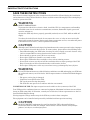
1
POWER AVAILABILITY PowerSure PSI™ USER MANUAL 1000 - 3000VA 120V TABLE OF CONTENTS IMPORTANT SAFETY INSTRUCTIONS . . . . . . . . . . . . . . . . . . . . . . . . . . . . . . . . . . . . . . . . . . . . . . . .1 1.0 GLOSSARY OF SYMBOLS . . . . . . . . . . . . . . . . . . . . . . . . . . . . . . . . . . . . . . . . . . . . . . . . . .3 2.0 INTRODUCTION . . . . . . . . . . . . . . . . . . . . . . . . . . . . . . . . . . . . . . . . . . . . . . . . . . . . . . . . . .4 3.0 MAJOR COMPONENTS . . . . . . . . . . . . . . . . . . . . . . . . . . . . . . . . . . . . . . . . . . . . . . . . . . . .6 3.1 Transient Voltage Surge Suppression (TVSS) and EMI/RFI Filters. . . . . . . . . . . . . . . . . . . . 6 3.2 Relay . . . . . . . . . . . . . . . . . . . . . . . . . . . . . . . . . . . . . . . . . . . . . . . . . . . . . . . . . . . . . . . . . . . . . . 6 3.3 Automatic Voltage Regulator. . . . . . . . . . . . . . . . . . . . . . . . . . . . . . . . . . . . . . . . . . . . . . . . . . . 7 3.4 Battery Charger . . . . . . . . . . . . . . . . . . . . . . . . . . . . . . . . . . . . . . . . . . . . . . . . . . . . . . . . . . . . . 7 3.5 Battery . . . . . . . . . . . . . . . . . . . . . . . . . . . . . . . . . . . . . . . . . . . . . . . . . . . . . . . . . . . . . . . . . . . . 7 3.6 Inverter—1000/1440 Models Only. . . . . . . . . . . . . . . . . . . . . . . . . . . . . . . . . . . . . . . . . . . . . . . 7 3.7 DC-to-DC Converter—2200/3000 Models Only . . . . . . . . . . . . . . . . . . . . . . . . . . . . . . . . . . . . 7 3.8 Bi-Directional Converter—2200/3000 Models Only . . . . . . . . . . . . . . . . . . . . . . . . . . . . . . . . . 7 4.0 WHAT’S INCLUDED . . . . . . . . . . . . . . . . . . . . . . . . . . . . . . . . . . . . . . . . . . . . . . . . . . . . . . .8 5.0 INSTALLATION . . . . . . . . . . . . . . . . . . . . . . . . . . . . . . . . . . . . . . . . . . . . . . . . . . . . . . . . . .9 5.1 Preparation . . . . . . . . . . . . . . . . . . . . . . . . . . . . . . . . . . . . . . . . . . . . . . . . . . . . . . . . . . . . . . . . . 9 5.2 Tower UPS Installation . . . . . . . . . . . . . . . . . . . . . . . . . . . . . . . . . . . . . . . . . . . . . . . . . . . . . . . 9 5.3 Rack-Mount UPS Conversion and Installation . . . . . . . . . . . . . . . . . . . . . . . . . . . . . . . . . . . 10 5.4 External Battery Cabinet Installation . . . . . . . . . . . . . . . . . . . . . . . . . . . . . . . . . . . . . . . . . . 13 6.0 CONTROLS AND INDICATORS. . . . . . . . . . . . . . . . . . . . . . . . . . . . . . . . . . . . . . . . . . . . . . . 14 6.1 ON/Alarm Silence/Battery Test Button . . . . . . . . . . . . . . . . . . . . . . . . . . . . . . . . . . . . . . . . . 14 6.2 OFF Button. . . . . . . . . . . . . . . . . . . . . . . . . . . . . . . . . . . . . . . . . . . . . . . . . . . . . . . . . . . . . . . . 14 6.3 Voltage Programming Button . . . . . . . . . . . . . . . . . . . . . . . . . . . . . . . . . . . . . . . . . . . . . . . . . 15 6.4 Load Level Indicators—4 green, 1 amber . . . . . . . . . . . . . . . . . . . . . . . . . . . . . . . . . . . . . . . . 15 6.5 Battery Level Indicators—5 green . . . . . . . . . . . . . . . . . . . . . . . . . . . . . . . . . . . . . . . . . . . . . 15 6.6 AC Input Indicator—Green . . . . . . . . . . . . . . . . . . . . . . . . . . . . . . . . . . . . . . . . . . . . . . . . . . . 15 6.7 Buck/Boost Indicator—Green . . . . . . . . . . . . . . . . . . . . . . . . . . . . . . . . . . . . . . . . . . . . . . . . . 15 6.8 Battery Indicator—Green/Amber . . . . . . . . . . . . . . . . . . . . . . . . . . . . . . . . . . . . . . . . . . . . . . 15 6.9 Over Temp Indicator—Amber . . . . . . . . . . . . . . . . . . . . . . . . . . . . . . . . . . . . . . . . . . . . . . . . . 16 6.10 Fault Indicator—Red . . . . . . . . . . . . . . . . . . . . . . . . . . . . . . . . . . . . . . . . . . . . . . . . . . . . . . . . 16 7.0 MODES OF OPERATION . . . . . . . . . . . . . . . . . . . . . . . . . . . . . . . . . . . . . . . . . . . . . . . . . . . 17 7.1 Normal Mode . . . . . . . . . . . . . . . . . . . . . . . . . . . . . . . . . . . . . . . . . . . . . . . . . . . . . . . . . . . . . . 17 i 7.2 Buck/Boost Mode . . . . . . . . . . . . . . . . . . . . . . . . . . . . . . . . . . . . . . . . . . . . . . . . . . . . . . . . . . . 17 7.3 Battery Mode . . . . . . . . . . . . . . . . . . . . . . . . . . . . . . . . . . . . . . . . . . . . . . . . . . . . . . . . . . . . . . 18 7.4 Battery Recharge Operation . . . . . . . . . . . . . . . . . . . . . . . . . . . . . . . . . . . . . . . . . . . . . . . . . . 18 8.0 COMMUNICATIONS . . . . . . . . . . . . . . . . . . . . . . . . . . . . . . . . . . . . . . . . . . . . . . . . . . . . . . 19 8.1 DB-9 Connector . . . . . . . . . . . . . . . . . . . . . . . . . . . . . . . . . . . . . . . . . . . . . . . . . . . . . . . . . . . . 19 8.2 Remote Shutdown Via the DB-9 Connector . . . . . . . . . . . . . . . . . . . . . . . . . . . . . . . . . . . . . . 19 8.2.1 8.2.2 Any Mode Shutdown—Via Pins 5 & 6. . . . . . . . . . . . . . . . . . . . . . . . . . . . . . . . . . . . . . . . . . . . 19 Battery Mode Shutdown—Via Pins 4 & 5. . . . . . . . . . . . . . . . . . . . . . . . . . . . . . . . . . . . . . . . . 19 8.3 USB Interface Port . . . . . . . . . . . . . . . . . . . . . . . . . . . . . . . . . . . . . . . . . . . . . . . . . . . . . . . . . . 20 8.4 Data Line Protection Connectors. . . . . . . . . . . . . . . . . . . . . . . . . . . . . . . . . . . . . . . . . . . . . . . 20 8.5 UPS Intelligent Communications . . . . . . . . . . . . . . . . . . . . . . . . . . . . . . . . . . . . . . . . . . . . . . 20 9.0 VOLTAGE PROGRAMMING PROCEDURE . . . . . . . . . . . . . . . . . . . . . . . . . . . . . . . . . . . . . . . 21 10.0 MAINTENANCE . . . . . . . . . . . . . . . . . . . . . . . . . . . . . . . . . . . . . . . . . . . . . . . . . . . . . . . . . 22 10.1 Cleaning the UPS . . . . . . . . . . . . . . . . . . . . . . . . . . . . . . . . . . . . . . . . . . . . . . . . . . . . . . . . . . . 22 10.2 Maintaining Batteries . . . . . . . . . . . . . . . . . . . . . . . . . . . . . . . . . . . . . . . . . . . . . . . . . . . . . . . 22 10.3 Battery Replacement . . . . . . . . . . . . . . . . . . . . . . . . . . . . . . . . . . . . . . . . . . . . . . . . . . . . . . . . 22 10.3.1 Internal Battery Replacement Procedure . . . . . . . . . . . . . . . . . . . . . . . . . . . . . . . . . . . . . . . . . 23 11.0 TROUBLESHOOTING . . . . . . . . . . . . . . . . . . . . . . . . . . . . . . . . . . . . . . . . . . . . . . . . . . . . . 24 12.0 SPECIFICATIONS . . . . . . . . . . . . . . . . . . . . . . . . . . . . . . . . . . . . . . . . . . . . . . . . . . . . . . . .26 12.1 Product Warranty Registration . . . . . . . . . . . . . . . . . . . . . . . . . . . . . . . . . . . . . . . . . . . . . . . . 29 ii FIGURES Figure 1 Figure 2 Figure 3 Figure 4 Figure 5 Figure 6 Figure 7 Figure 8 Figure 9 Figure 10 Figure 11 Figure 12 Figure 13 Figure 14 Figure 15 Figure 16 Figure 17 Figure 18 Figure 19 Figure 20 Front view of UPS . . . . . . . . . . . . . . . . . . . . . . . . . . . . . . . . . . . . . . . . . . . . . . . . . . . . . . . . . . . . . . . . 4 1000 and 1440VA PSI—rear view . . . . . . . . . . . . . . . . . . . . . . . . . . . . . . . . . . . . . . . . . . . . . . . . . . . 5 2200VA PSI—rear view . . . . . . . . . . . . . . . . . . . . . . . . . . . . . . . . . . . . . . . . . . . . . . . . . . . . . . . . . . . 5 3000VA PSI—rear view . . . . . . . . . . . . . . . . . . . . . . . . . . . . . . . . . . . . . . . . . . . . . . . . . . . . . . . . . . . 5 Line diagram of PowerSure PSI 1000VA & 1440VA . . . . . . . . . . . . . . . . . . . . . . . . . . . . . . . . . . . . 6 Line diagram of PowerSure PSI 2200VA & 3000VA . . . . . . . . . . . . . . . . . . . . . . . . . . . . . . . . . . . . 6 Support base for tower configuration. . . . . . . . . . . . . . . . . . . . . . . . . . . . . . . . . . . . . . . . . . . . . . . . . 9 Rack mount handles . . . . . . . . . . . . . . . . . . . . . . . . . . . . . . . . . . . . . . . . . . . . . . . . . . . . . . . . . . . . . 10 Fixed rails with inner members extended . . . . . . . . . . . . . . . . . . . . . . . . . . . . . . . . . . . . . . . . . . . . 10 Rack mounting rails and slide assemblies. . . . . . . . . . . . . . . . . . . . . . . . . . . . . . . . . . . . . . . . . . . . 11 REPO switch connections . . . . . . . . . . . . . . . . . . . . . . . . . . . . . . . . . . . . . . . . . . . . . . . . . . . . . . . . . 13 Load level indicators—4 green, 1 amber . . . . . . . . . . . . . . . . . . . . . . . . . . . . . . . . . . . . . . . . . . . . . 15 Battery level indicators—5 green. . . . . . . . . . . . . . . . . . . . . . . . . . . . . . . . . . . . . . . . . . . . . . . . . . . 15 Normal mode operation with 26-50% load. . . . . . . . . . . . . . . . . . . . . . . . . . . . . . . . . . . . . . . . . . . . 17 Buck/Boost mode operation with 51-75% load and 21-40% battery capacity . . . . . . . . . . . . . . . . 17 Battery mode at 61 – 80% battery capacity. . . . . . . . . . . . . . . . . . . . . . . . . . . . . . . . . . . . . . . . . . . 18 Low Battery mode . . . . . . . . . . . . . . . . . . . . . . . . . . . . . . . . . . . . . . . . . . . . . . . . . . . . . . . . . . . . . . . 18 Load Level Indicators . . . . . . . . . . . . . . . . . . . . . . . . . . . . . . . . . . . . . . . . . . . . . . . . . . . . . . . . . . . . 21 Battery replacement procedure . . . . . . . . . . . . . . . . . . . . . . . . . . . . . . . . . . . . . . . . . . . . . . . . . . . . 23 Status indicators . . . . . . . . . . . . . . . . . . . . . . . . . . . . . . . . . . . . . . . . . . . . . . . . . . . . . . . . . . . . . . . 24 TABLES Table 1 Table 2 Table 3 Table 4 Table 5 DB-9 pin assignment . . . . . . . . . . . . . . . . . . . . . . . . . . . . . . . . . . . . . . . . . . . . . . . . . . . . . . . . . . . . Troubleshooting chart. . . . . . . . . . . . . . . . . . . . . . . . . . . . . . . . . . . . . . . . . . . . . . . . . . . . . . . . . . . . UPS specifications. . . . . . . . . . . . . . . . . . . . . . . . . . . . . . . . . . . . . . . . . . . . . . . . . . . . . . . . . . . . . . . Battery cabinet specifications . . . . . . . . . . . . . . . . . . . . . . . . . . . . . . . . . . . . . . . . . . . . . . . . . . . . . Battery run times . . . . . . . . . . . . . . . . . . . . . . . . . . . . . . . . . . . . . . . . . . . . . . . . . . . . . . . . . . . . . . . iii 19 25 26 27 28 iv IMPORTANT SAFETY INSTRUCTIONS SAVE THESE INSTRUCTIONS This manual contains important safety instructions that should be followed during the installation and maintenance of the UPS and batteries. Please read this manual thoroughly before attempting to install or operate this UPS. ! WARNING SAFETY PRECAUTIONS To prevent the risk of fire or electric shock, install the UPS in a temperature and humidity controlled room, free of conductive contaminants, moisture, flammable liquids, gases and corrosive substances. Operate the UPS only from a properly grounded (earthed) 110-127 VAC, 50Hz or 60Hz AC supply. To reduce the risk of electric shock, do not remove the cover, as it has no user-serviceable parts inside except the internal battery pack. Some components are live, even when AC power is disconnected. For service, contact a qualified technician. ! CAUTION Although your UPS has been designed and manufactured to ensure personal safety, improper use can result in electrical shock or fire. To ensure safety, please observe the following rules: • Turn Off and unplug your UPS before cleaning. Do not use liquid or aerosol cleaners. A dry cloth is recommended to remove dust from the surface of your UPS. • Do not install or operate your UPS in or near water. • Do not place UPS on an unstable cart, stand or table. • Do not place UPS under direct sunlight or close to heat emitting sources. • Never block or insert any objects into the ventilation holes or other openings of the UPS. Keep all vents free of dust accumulation that could restrict air flow. • Do not place UPS power cord in any area where it may get damaged by heavy objects. ! WARNING If your UPS demonstrates any of the following conditions, turn Off and unplug your UPS from the outlet and contact your local dealer, Liebert representative or Liebert Worldwide Support Group: • • • • The power cord or plug is damaged. Liquid has been spilled on the UPS. The circuit protector trips frequently. The UPS does not operate in accordance with the user manual. CONDITIONS OF USE: The input receptacle must be within 10 feet (3 meters) of the UPS. Your UPS provides conditioned power to connected equipment. Maximum load must not exceed that shown on UPS rating label. If uncertain, consult your local dealer, Liebert representative or the Liebert Worldwide Support Group. Placing magnetic storage media on top of the UPS may result in data corruption. The equipment can be installed and operated by individuals without previous training. ! CAUTION DO NOT CONNECT equipment that could overload the UPS or demand half-wave rectification from the UPS, for example: electric drills, vacuum cleaners, laserjet/inkjet printers, hair dryers, overhead projectors. 1 ! CAUTION BATTERY HANDLING PRECAUTIONS Servicing of batteries should be performed or supervised by personnel knowledgeable of batteries and required precautions. Keep unauthorized personnel away from the batteries. A battery can present a risk of electrical shock and high short-circuit current. The following precautions should be observed when working on batteries: • • • • Remove watches, rings, and other metal objects. Use tools with insulated handles. Do not dispose battery or batteries in a fire. The battery may explode. Do not open or mutilate the battery or batteries. Released electrolyte is harmful to skin and eyes. It may be toxic. • When replacing the battery, use same number and type of battery as the suitable recommended type of battery listed in specification table in back of this manual. • Handle, transport and recycle batteries in accordance with local regulations. NOTE This device complies with part 15 of the FCC Rules. Operation is subject to the following two conditions: (1) This device may not cause harmful interference, and (2) this device must accept any interference received, including interference that may cause undesired operation. This equipment uses, generates and can radiate radio frequency energy and, if not installed and used in accordance with the instructions, may cause harmful interference with radio communications. However, there is no guarantee that interference will not occur in a particular installation. If this equipment does cause harmful interference to radio or television reception, which can be determined by turning the equipment Off and On, the user is encouraged to try to correct the interference by one or more of the following measures: • Reorient or relocate the receiving antenna. • Increase the separation between the UPS and the receiver. • Connect the UPS into an outlet on a circuit different from the one on which the receiver is connected. 2 Glossary of Symbols 1.0 GLOSSARY OF SYMBOLS . Risk of electrical shock Indicates caution followed by important instructions i Requests the user to consult the manual Indicates the unit contains a valve-regulated lead acid battery Recycle DC voltage Equipment grounding conductor Bonded to ground AC voltage ON/Alarm Silence/Battery Test OFF Voltage Programming Button 3 Introduction 2.0 INTRODUCTION Congratulations on your choice of the Liebert PowerSure™ PSI Uninterruptible Power Supply (UPS). It provides conditioned power to microcomputers and other sensitive electronic equipment. Upon generation, AC power is clean and stable. However, during transmission it may be subject to voltage sags, spikes, or complete power failure which may interrupt computer operations, cause data loss, or even damage equipment. The PowerSure PSI protects equipment from these disturbances. The PowerSure PSI comes in nominal power ratings of 1000, 1440, 2200, or 3000 VA. Refer to the Specifications section for details. The PowerSure PSI is a 2U, line-interactive UPS that may be installed in a rack or used in a tower configuration. A line-interactive UPS continuously conditions and regulates its output voltage, whether utility power is present or not. It supplies connected equipment with clean, sinewave power to simulate the power generated by the utility. Sensitive electronic equipment operates best from sinewave power. For ease of use, the PowerSure PSI contains Status Indicators to display Load Level, Battery Level, Buck/Boost, Over Temperature and Battery. It also provides self-diagnostic tests, a combination ON/ Alarm Silence/Battery Test button, an OFF button and Voltage Programming button. The PowerSure PSI has USB, DB-9 (RS232/contact closure) and Intellislot interface ports for communications between the UPS and a LAN server or other computer systems. The DB-9 port provides detailed operating information including voltages, currents, and alarm status to the host system when used in conjunction with Liebert’s MultiLink software. MultiLink software can also remotely control UPS operation. The USB port provides detailed operating information and alarm status to the host system when used in conjunction with the Liebert Human Interface Device (HID) and Microsoft Power Manager software. Figure 1 Front view of UPS Fault Indicator OFF Button Load Level Indicators ON/Alarm Silence/ Battery Test Button Battery Level Indicators Voltage Programming Button UPS Status Indicators UPS Display (bezel removed) 4 Introduction Figure 2 1000 and 1440VA PSI—rear view REPO OUT REPO IN 1 2 3 4 Output Receptacles Data Line Connectors Intellislot Port BATTERY CONNECTOR 1440VA/DC 48V/30A 1000VA/DC 48V/20A RS-232 PHONE / FAX / MODEM / NETWORK PROTECTION LOAD 2 LOAD 1 + INPUT INPUT BREAKER PUSH TO RESET INTELLISLOT RS232 (DB-9) Port USB Port Figure 3 Attached Power Cord, 10ft (3m) 2200VA PSI—rear view REPO Intellislot Port Circuit Breaker REPO INPUT BREAKER PUSH TO RESET 1 2 3 4 External Battery Cabinet Connector Circuit Breaker Data Line Connectors Output Receptacles Circuit Breaker LOAD 1 BREAKER PHONE / FAX / MODEM / NETWORK PROTECTION BATTERY CONNECTOR DC 72V / 30A IN 15A/120VAC RS-232 INPUT + OUT LOAD 2 BREAKER INTELLISLOT USB Port Figure 4 RS232 (DB-9) Port External Battery Cabinet Connector 3000VA PSI—rear view REPO Intellislot Port Circuit Breaker REPO INPUT BREAKER PUSH TO RESET 1 2 3 4 Circuit Breaker Attached Power Cord, 10ft (3m) Data Line Connectors Output Receptacles Circuit Breaker LOAD 1 BREAKER PHONE / FAX / MODEM / NETWORK PROTECTION BATTERY CONNECTOR DC 72V / 40A IN 15A / 120 VAC RS-232 INPUT + OUT LOAD 3 LOAD 2 BREAKER INTELLISLOT USB Port RS232 (DB-9) Port Circuit Breaker Attached Power Cord, 10ft (3m) 5 External Battery Cabinet Connector Major Components 3.0 MAJOR COMPONENTS Figure 5 Line diagram of PowerSure PSI 1000VA & 1440VA Input EMI/RFI Filter Relay AVR Transformer Charger Battery Inverter Output G G Figure 6 Line diagram of PowerSure PSI 2200VA & 3000VA Input EMI/RFI Filter Relay AVR Transformer Charger Battery DC-to-DC Converter Output Bi-Directional Converter G 3.1 G Transient Voltage Surge Suppression (TVSS) and EMI/RFI Filters These UPS components provide surge protection and filter both electromagnetic interference (EMI) and radio frequency interference (RFI). They minimize surges or interference present in the utility line and keep the sensitive equipment protected. 3.2 Relay In Normal mode the Relay passes utility AC power to the connected load. When input utility voltage or frequency is outside acceptable limits, the Relay activates and transfers the UPS to battery. 6 Major Components 3.3 Automatic Voltage Regulator The Automatic Voltage Regulator (AVR) protects connected equipment from power spikes, sags and other abnormalities by raising (boosting) or lowering (bucking) the output voltage as needed. This keeps the UPS output voltage within the connected equipment’s tolerance and accommodates wide utility voltage fluctuations without utilizing the batteries. 3.4 Battery Charger In Normal mode, the Battery Charger converts utility AC power into regulated DC power to float charge the battery. It is continuously charging the battery whenever the UPS is plugged into a power outlet and utility power is within acceptable limits - even if the UPS is turned Off. 3.5 Battery The PowerSure PSI utilizes valve-regulated, nonspillable, lead acid batteries. To maintain battery design life, operate the UPS in an ambient temperature of 68°F to 77°F (20°C to 25°C). Optional external battery cabinets are available to extend battery run times. 3.6 Inverter—1000/1440 Models Only In battery mode operation, the inverter utilizes the DC output of the battery and inverts it into precise, regulated, sinewave AC power. 3.7 DC-to-DC Converter—2200/3000 Models Only The DC-to-DC Converter utilizes energy from the battery system and raises the DC voltage to the optimum operating voltage for the Bi-Directional Converter. This allows the Bi-Directional Converter to operate continuously at its optimum efficiency and voltage, thus increasing reliability. 3.8 Bi-Directional Converter—2200/3000 Models Only In normal operation, the Bi-Directional Converter changes utility AC power into regulated DC power to “float charge” the battery system. This converter is continuously charging the battery whenever the UPS is plugged into a power outlet and utility power is within acceptable limits—even if the UPS is turned Off. When utility power fails, the Bi-Directional Converter draws energy from the battery through the DC-to-DC Converter and inverts it into a regulated sinewave supplying power to connected equipment. 7 What’s Included 4.0 WHAT’S INCLUDED The PowerSure PSI is shipped with the following items: • • • • • • • • • • • • PowerSure PSI user manual Warranty card MultiLink software CD MultiLink serial cable, 10 ft (3m) USB cable, 6 ft (1.8m) RJ-11 cord, 7 ft (2.1m) Rack mount handles Support base Fixed rails Mounting hardware (screws/washers) Front bezel Vertical display overlay MultiLink software CD Support base Vertical display overlay Fixed rails MultiLink serial cable 10 ft (3m) USB cable 6 ft (1.8m) Mounting hardware (screws & washers) 8 RJ-11 cord 7 ft (2.1m) Front bezel Rack mount handles Installation 5.0 INSTALLATION 5.1 Preparation 1. Visually inspect the UPS for freight damage. Report damage to the carrier and your local dealer or Liebert representative. ! CAUTION The UPS is heavy (see Table 4 - Battery cabinet specifications). Take proper precautions when lifting or moving it. 2. Decide where to place the PowerSure PSI. Install the UPS indoors in a controlled environment where it cannot be accidentally turned Off. Place it in an area of unrestricted airflow around the unit, away from water, flammable liquids, gases, corrosives, and conductive contaminants. Maintain a minimum clearance of 4 inches (100mm) in the front and rear of the UPS. Maintain an ambient temperature range of 32°F to 104°F (0°C to 40°C). NOTE UPS operation in temperatures above 77°F (25°C) reduces battery life. 3. The PowerSure PSI may be installed in either a tower configuration or in a rack, depending on available space and use considerations. Determine the type of installation and follow the appropriate instructions in either Tower UPS Installation or Rack-Mount UPS Conversion and Installation. 5.2 Tower UPS Installation When using the PowerSure PSI in a tower configuration, use the included support base (shown below, left) to stabilize the UPS. If two or more battery cabinets are added, the spacers—included with the battery cabinets—should be used to accommodate the additional cabinets. Figure 7 Support base for tower configuration Tower Stand - Fully Extended Spacers Can be Added to Accommodate External Battery Cabinets Connectors Snap into Slots on Base 1. To orient the display for vertical viewing, remove the front plastic bezel by pulling forward evenly on both sides. 2. Peel the backing from the vertical display overlay and apply to the existing display. 3. Snap the front bezel back into place. 9 Installation 5.3 Rack-Mount UPS Conversion and Installation NOTE When rack mounted, the UPS must be supported by a shelf, slide rails, brackets or fixed rails on each side. The rack mount handles WILL NOT support the weight of the UPS. They are used to move the UPS into and out of the rack. 1. For fixed rail installations, install the rack mount handles using four (4) M4x6 screws (see Figure 8). Figure 8 Rack mount handles Two (2) M4x6 Flat Head Screws Two (2) M4x6 Flat Head Screws Rack Mount Handles M4x6 Flat Screw 2. Unpack the two fixed rail assemblies and mounting hardware. Loosen the wing nuts and extend the inner members to their outermost position (see Figure 9). Figure 9 Fixed rails with inner members extended Wing Nuts for Adjustment Adjustable Slide Assembly Adjustable Length Maximum 800 mm Minimum 485 mm ! CAUTION Reduce the risk of tipping the rack enclosure by placing the UPS or battery cabinet in the lowest possible rack position. 3. Determine the height position inside the rack enclosure where you want to mount the UPS or battery cabinet. Make sure fixed rails are at the same mounting height on each of the four (4) rack mounting rails. 10 Installation 4. Attach the two (2) fixed rails to the racks mounting rails. The fixed rail assemblies fit on the inside of the rack mounting rails. 5. Insert two (2) M5 flat head screws loosely (finger-tight) into the top and bottom holes on the front of the fixed rail assembly (see Figure 10). 6. Extend fixed rail by sliding inner member backward until it touches the rear rack mounting rail. 7. Insert two (2) M5 screws loosely (finger-tight) into top and bottom holes on the rear of the fixed rail assembly. 8. Check alignment of fixed rails and tighten all screws to ensure locking action. Figure 10 Rack mounting rails and slide assemblies B B A A A A - Washer B - M5x12 Flat Screw A B B 9. Lay the UPS in rack-mounting position on the fixed rails. The UPS should move smoothly forward and backward on the fixed rails. If not, recheck alignment. ! CAUTION Lifting equipment into rack may be a two-person job, depending on weight of equipment. 10. Use the extra M5 screws provided, secure front of the UPS to rack mounting rails to prevent the UPS from sliding out of position. 11. Plug the PowerSure PSI’s attached 10 ft. (3m) Vertical overlay power cord into a dedicated wall receptacle for tower properly protected by a circuit breaker or fuse in UPS accordance with national and local electrical codes. Use a 15A-rated device for the 1000 or 1440 VA units, 30 amp for the 2200 VA or 3000 VA units. The wall receptacle must be grounded. 12. Turn On the UPS by pressing the ON button. Check that the AC Input Indicator is not flashing. If it is flashing, refer to 11.0 - Troubleshooting. Then turn On the connected equipment. The UPS Horizontal is now providing conditioned power to your overlay for equipment. rack UPS ! CAUTION To maintain safety (SELV) barriers and electromagnetic compatibility, signal cables should be segregated and run separately from power cables. 11 Installation 13. Connect Phone/Fax/DSL/Network/Modem devices to data line connectors. RJ11/RJ45 connection OUT REPO IN BATTERY CONNECTOR 1440VA/DC 48V/30A 1000VA/DC 48V/20A PHONE / FAX / MODEM / NETWORK PROTECTION RS-232 1 2 3 4 LOAD 2 LOAD 1 + INPUT INPUT BREAKER PUSH TO RESET INTELLISLOT 14. Communication options (see 8.0 - Communications for details): Option 1 - Serial Communications Serial communications provides parametric data, for example, input voltage and battery voltage. a. Connect MultiLink serial cable included with the UPS to communications port. b. Install the MultiLink software. The software and installation instructions, as well as the user manual, are on the CD included in the PowerSure PSI package. Option 2 - Contact Closure Communications Contact Closure communications provides on-battery and low-battery signals for orderly shutdown. a. Refer to the MultiLink user manual for instructions on making your own contact closure cable. b. Install the MultiLink software. The software and installation instructions, as well as the user manual, are on the CD included in the PowerSure PSI package. Option 3 - USB Communications a. Connect USB cable provided with the UPS to the PSI’s USB port and the USB port on your computer. The PSI will work automatically with your built-in power management software on Windows XP and 2000 and Mac OS 10.2 or later (see 8.3 - USB Interface Port for details). Option 4 – Intellislot The UPS contains one communication slot, called “Intellislot™,” to allow the operator to field install optional communication cards. These optional cards allow the UPS to communicate via either OpenComms Web Card (OCWEBCARD), connected directly to the LAN; or Intellislot Relay Interface card (RELAYCARD-INT) communication card. Once the OCWEBCARD is installed, the Serial communication via the RS232 is disabled. The USB, Intellislot, and Contact Closure communications operate in parallel. 15. REPO Switch—The PowerSure PSI is equipped with a Remote Emergency Power Off (REPO) switch. The user must supply a means of interfacing with the REPO circuit to allow disconnecting the UPS input feeder breaker to remove all sources of power to the UPS and connected equipment to comply with national and local wiring codes and regulations. 12 Installation Figure 11 REPO switch connections REPO Connection REPO Switch as shipped 1 2 3 4 REPO connections for normally open switch system 1 2 3 REPO connections for normally closed switch system (fail-safe) 4 1 2 3 4 Key to REPO switch connections 1. 24 VDC, 2. Sense 3. Sense 4. Ground External Battery Cabinet Installation Optional Liebert external battery cabinets may be connected to the UPS to provide additional battery run time. External battery cabinets are designed to be placed all on one side of the UPS or stacked beneath the UPS. The run time is limited to a maximum of four (4) hours. ! CAUTION The external battery cabinet(s) are heavy (see 12.0 - Specifications). External battery cabinets can be used in rack-mount or tower configuration. Take proper precautions when lifting them. 1. Visually inspect the external battery cabinet for freight damage. Report damage to the carrier and your local dealer or Liebert representative. 2. The rack-mount handles are shipped with the external battery cabinet and may be installed at this time (see 5.3 - Rack-Mount UPS Conversion and Installation). 3. Fixed rails and securing hardware ship with the external battery cabinet. Fasten the fixed rails into position with the screws per the instructions included with the UPS. Repeat Steps 1 through 10 from 5.3 - Rack-Mount UPS Conversion and Installation. 4. Use the support bases included with the UPS for the tower option to prevent tip-over. One additional set of support base spacers ships with each external battery cabinet. 5. Connect the supplied external battery cabinet cable to the rear of the external battery cabinet, then to the rear of the UPS, as shown at right. 6. The UPS is now equipped with additional backup battery run time. For approximate battery run times, refer to Table 5 - Battery run times. BATTERY CONNECTOR 1440VA/DC 48V/30A 1000VA/DC 48V/20A BATTERY CONNECTOR 1440VA/DC 48V/30A 1000VA/DC 48V/20A OUT REPO IN 1 2 3 4 BATTERY CONNECTOR 1440VA/DC 48V/30A 1000VA/DC 48V/20A PHONE / FAX / MODEM / NETWORK PROTECTION RS-232 5.4 LOAD 2 LOAD 1 + INPUT - INPUT BREAKER PUSH TO RESET INTELLISLOT 13 Controls and Indicators 6.0 CONTROLS AND INDICATORS All indicators illuminated for illustrative purposes only. 6.1 ON/Alarm Silence/Battery Test Button This button controls output power to connected load(s) and has three functions: • On • Alarm Silence • Battery Test ON—When the UPS is Off, pressing the ON/Alarm Silence/Battery Test button for more than one (1) second will start the UPS, and an audible alarm sounds briefly. The UPS is capable of starting on battery (battery start). Alarm Silence—When a UPS audible alarm is active, pressing and releasing the ON/Alarm Silence/ Battery Test button will silence the active audible alarm, whether utility power is present or not. Once the alarm silence function has been activated, all active audible alarms will remain silenced until a new alarm condition is detected. NOTE The LOW BATTERY, OVER TEMP and OVERLOAD warning audible alarms CANNOT be silenced. Battery Test—To initiate a manual battery test, press the ON/Alarm Silence/Battery Test button for at least one second while operating from utility power with no alarm conditions present. • If all five (5) Battery indicators are not illuminated, allow the UPS to recharge the batteries for 24 hours. • After 24 hours, retest the batteries. • After the batteries have been retested, if all five (5) Battery indicators are not illuminated, contact your local dealer, Liebert representative or Liebert Worldwide Support Group. 6.2 OFF Button When the UPS is on (in either Normal or Battery mode), pressing the OFF button for more than one (1) second will shut down the UPS. An audible alarm sounds briefly. 14 Controls and Indicators 6.3 Voltage Programming Button The PowerSure PSI contains a Voltage Programming button that allows the operator to select the nominal utility voltage. This setting changes the utility transfer points (low and high) of the UPS and the nominal output voltage when operating in Battery mode. The operator can select between 110, 120 and 127 VAC output. The factory-default setting is 120 VAC. The Voltage Programming button is a push button type and is behind the plastic bezel on the front panel of the UPS. To access the button, the front bezel must be removed. 6.4 Load Level Indicators—4 green, 1 amber The Load Level Indicators display the approximate electrical load placed upon the UPS. The UPS Load Level Indicators are displayed in 25% increments as shown in Figure 12. Figure 12 Load level indicators—4 green, 1 amber Upon detection of an output overload condition, the amber overload (>100%) indicator flashes and an audible alarm activates. If the UPS shuts down due to an overload condition, the amber overload (>100%) indicator illuminates (see Troubleshooting section for details). 6.5 Battery Level Indicators—5 green The Battery Level Indicators display the approximate battery capacity. The approximate battery capacity is displayed when the UPS is operating in Normal, Buck/Boost, or Battery mode. The Battery Level Indicators are displayed in 20% increments as shown in Figure 13: Figure 13 Battery level indicators—5 green The PowerSure PSI is equipped with automatic and remote battery test features. The automatic test occurs every 14 days if utility has not been interrupted; this option may be configured by the user. Should the battery fail this test, the amber Battery Indicator will be illuminated and an alarm will sound (see Troubleshooting section for details). The remote test feature functions with MultiLink 3.x software and can remotely initiate the battery test. 6.6 AC Input Indicator—Green The AC Input Indicator illuminates when utility power is available and within the input specifications. This indicator flashes when the UPS detects a Site Wiring Fault (line-neutral reversal or neutral not grounded properly) (see Troubleshooting section for details). 6.7 Buck/Boost Indicator—Green The Buck/Boost Indicator illuminates when the UPS is operating in Boost mode to compensate for a low utility voltage condition. This indicator flashes when the UPS is operating in Buck mode to compensate for a high utility voltage condition (see Troubleshooting section for details). 6.8 Battery Indicator—Green/Amber The Battery Indicator illuminates green when the UPS is operating on battery and flashes green when a low battery condition occurs. The Battery Indicator illuminates amber when a bad battery is detected, indicating that the batteries need to be replaced (see Troubleshooting section for details). 15 Controls and Indicators 6.9 Over Temp Indicator—Amber The Over Temp Indicator flashes when the UPS detects an over temperature condition. This indicator illuminates when the UPS shuts down due to an over temperature condition (see Troubleshooting section for details). 6.10 Fault Indicator—Red The Fault Indicator illuminates when the UPS detects an internal problem (see Troubleshooting section). 16 Modes of Operation 7.0 MODES OF OPERATION 7.1 Normal Mode During Normal mode operation, the PowerSure PSI supplies conditioned, computer-grade power to the connected equipment: utility power passes through the TVSS circuitry and the EMI/RFI filters and then through the Inverter (1000VA & 1440VA) / Bi-Directional Converter (2200VA & 3000VA) to connected equipment. When the UPS is in Normal mode, the AC Input Indicator illuminates green. The UPS display in Figure 14 shows the UPS operating in Normal mode with 26% - 50% load connected to the output. Figure 14 Normal mode operation with 26-50% load Utility power present ... ... and within operational limits The PowerSure PSI continuously monitors the batteries to maintain them in a fully charged state. The battery charger operates whenever AC power is present, even if the UPS is switched Off. By default, the UPS is set to perform an automatic battery test after it has been operating continuously for two (2) weeks. The automatic battery test can be disabled via MultiLink. 7.2 Buck/Boost Mode The Automatic Voltage Regulator (AVR) circuitry compensates for fluctuations in utility power, such as voltage surges and sags. When the PowerSure PSI detects an abnormality, it raises the undervoltage (boost) or lowers the overvoltage (buck) as needed. The AVR operates automatically and maintains the output voltage to the connected critical equipment, without utilizing the batteries. The Buck/Boost Indicator flashes green when the UPS is operating in Buck mode and illuminates green when the UPS is operating in Boost mode (see Troubleshooting section for details). Figure 15 Buck/Boost mode operation with 51-75% load and 21-40% battery capacity Indicator shows UPS in Boost Mode (solid green) 17 Modes of Operation 7.3 Battery Mode The UPS switches to Battery mode in the event of an extreme input voltage/frequency condition or complete utility failure. The battery system supplies power through the Inverter (1000VA & 1440VA) or through the DC-to-DC converter to the Bi-Directional Converter (2200VA & 3000VA) to generate power for the connected equipment. When the UPS is in Battery mode, the Battery Indicator illuminates green and an alarm sounds every 10 seconds. As capacity decreases, fewer indicators remain illuminated. Figure 16 shows the UPS in Battery mode with 61% - 80% battery capacity remaining. Figure 16 Battery mode at 61 – 80% battery capacity Battery Indicator illuminated When a low battery condition occurs, the Battery Indicator flashes green and the alarm sounds every half-second. The default low battery warning is two (2) minutes but can be configured via MultiLink. For more information, refer to Troubleshooting section. Figure 17 Low Battery mode Battery Indicator flashes green For approximate battery run times, refer to Table 5 - Battery run times. These run times are approximates based on resistive load and an ambient temperature of 77°F (25°C). To increase this time, turn Off non-essential pieces of equipment, such as idle computers and monitors, or add external battery cabinets. ! 7.4 CAUTION Turning Off the UPS while it is in battery mode will result in loss of output power. Battery Recharge Operation Once utility power is restored, the UPS resumes normal operation. At this time, the Battery Charger begins recharging. 18 Communications 8.0 COMMUNICATIONS 8.1 DB-9 Connector The UPS has a DB-9 (9 pin female) connector on the rear to allow UPS status communications with a computer system running MultiLink software. The DB-9 is capable of supplying serial communication, on battery and low battery signals. MultiLink, Liebert’s UPS monitoring and shutdown software, is shipped with the UPS, along with a 10 ft. (3m) DB-9 cable required for running MultiLink. When MultiLink is installed on the host computer, the UPS can signal “on battery” and “low battery” using opto-couplers. When the UPS is operating in Battery mode, it can receive a signal from the host computer system that will shut down the UPS (after gracefully shutting down the operating system on the host computer system) when the remaining battery run time is low. The timing of the signal depends on MultiLink’s configuration settings. This shutdown signal (5-12VDC) must have a duration of at least 2 seconds for the UPS to be shut down. The UPS communicates via serial communications using Liebert ESP II protocol. Table 1 DB-9 pin assignment DB-9 Pin Assignment Description 1 2 3 4 5 6 7 8 9 Low Battery (open collector) UPS TxD UPS RxD Battery Mode Shutdown (5-12V) Common Any Mode Shutdown (short to pin 5) Low Battery (open emitter) Utility Fail (open emitter) Utility Fail (open collector) Pin Assignment 6 7 8 Collector to Emitter* 9 330 Ohms 1 8.2 2 3 4 Open (+) Collector (-) 5 Open Emitter Remote Shutdown Via the DB-9 Connector The PowerSure PSI can be shut down remotely by shorting Pins 5 and 6 or via Pins 4 and 5 of the DB-9 connector. 8.2.1 Any Mode Shutdown—Via Pins 5 & 6 When Pin 6 is shorted to Pin 5, the UPS output is shut Off regardless of what mode the UPS is operating in. The UPS cannot be started as long as the pins are shorted. When the short is removed, the UPS output can be enabled by pressing the ON/Alarm Silence/Battery Test button. 8.2.2 Battery Mode Shutdown—Via Pins 4 & 5 While the UPS is operating on battery (with no battery test in progress), a 5-12VDC signal for 2 seconds or longer is required to signal a shutdown. Signals for less than 2 seconds are ignored. After Pin 4 receives the shutdown signal, a 2-minute shutdown timer inside the UPS begins a countdown. The timer cannot be stopped. If utility power returns during the 2-minute timer countdown, the shutdown timer continues until the end of 2 minutes and then the UPS turns Off. By default, autorestart is enabled so the UPS will restart after 10 seconds. If autorestart is disabled via MultiLink software, the UPS remains Off until a manual restart. 19 Communications 8.3 USB Interface Port The PowerSure PSI has a USB interface port for communication that will work with the built-in Microsoft Power Manger software on the user’s PC, if so equipped. It will provide UPS status and manages the automatic orderly shutdown of the computer. The UPS’s USB communications meet HID standard, version 1.11. All USB models are compatible with Microsoft Windows 2000, Windows XP and Mac OS 10.2 or later. All USB models ship with a 6 ft. (1.8m) USB cable. Microsoft, Windows, and the Windows logo are trademarks, or registered trademarks of Microsoft Corporation in the United States and/or other countries. 8.4 Data Line Protection Connectors Data line (in and out) connectors are on the rear of the UPS and provide transient voltage surge suppression (TVSS) for Phone/Fax/DSL/Internet/Modem devices. 8.5 UPS Intelligent Communications The PowerSure PSI is equipped with an Intellislot® port to provide advanced communication and monitoring options. Liebert’s MultiLink software continually monitors the UPS and can shut down your computer or server in the event of an extended power failure. MultiLink can also be configured for use without the serial cable when the Intellislot OCWEBCARD is installed in the UPS. Additionally, MultiLink can be configured to coordinate shutdown across the network with other computers running MultiLink when you purchase a MultiLink License Kit. For more information about the Intellislot OCWEBCARD and MultiLink License Kits, visit our Web site (www.liebert.com) or contact your local dealer or Liebert representative. Several option cards are available for use in the Intellislot port of the PowerSure PSI. The Intellislot OCWEBCARD provides SNMP and Web-based monitoring and control of the UPS across the network. The Intellislot MultiPort 4 Card allows you to install MultiLink software on four computers and coordinate shutdown in the event of a power failure. The RELAYCARD-INT provides dry contact relay outputs for custom-wired applications and delivers support for built-in shutdown for AS/400 systems. NOTE The USB, Intellislot and Contact Closure communications operate in parallel. Using the OCWEBCARD disables the Serial Communications of the DB-9. ! CAUTION To maintain safety (SELV) barriers and for electromagnetic compatibility, signal cables should be segregated and run separate from all other power cables, where applicable. 20 Voltage Programming Procedure 9.0 VOLTAGE PROGRAMMING PROCEDURE Figure 18 Load Level Indicators Load Level Indicators Voltage Programming Button 1. Remove the front bezel from the UPS. 2. UPS must be operating in Normal (AC) mode. NOTE Utility power will be applied to the connected load. 3. The AC Input, Load, and Battery Level Indicators should be lit. 4. Press the Voltage Programming button for at least 5 seconds to enter the Configuration mode. The UPS will beep and all of the indicators on the front panel display will flash on and off for about 5 seconds. The next cycle will display the current configuration, either 110, 120 or 127 VAC. One of the Load Level Indicators will be flashing. Initially, the 0%-25% Load Level Indicator will be flashing, indicating the default setting of 120V as shown in Figure 18. 5. Press the ON button to step through the voltage settings until the appropriate Load Level Indicator is flashing. 6. Press the Voltage Programming button. The UPS will return to Normal mode operation. The Voltage Programming button allows the operator to select the utility transfer voltage at which the UPS will switch to battery power. This also changes the inverter voltages. The voltage settings are as follows: Input Voltage Range Output Voltage (Battery Mode) 120V (230V) 85 - 145 VAC (default) 120VAC 110V (220V) 78 - 138 VAC 110VAC 127V (240V) 90 - 150 VAC 127VAC Setting 21 Maintenance 10.0 MAINTENANCE The PowerSure PSI UPS requires very little maintenance. Follow these practices to prevent problems. 10.1 Cleaning the UPS The following will help ensure trouble-free operation for years: • Vacuum dust from the ventilation intake occasionally. • Wipe the cover periodically with a dry cloth. 10.2 Maintaining Batteries The batteries are valve-regulated, nonspillable, lead acid and must be kept charged to retain their design life. The UPS continuously charges the batteries when connected to the utility supply, even while the UPS is switched Off. When storing the UPS, it is recommended to plug in the UPS for at least 24 hours every four to six months to ensure full recharge of the batteries. 10.3 Battery Replacement ! CAUTION A battery can present a risk of electrical shock and high short circuit current. The following precautions should be observed before replacing the batteries: • • • • Remove rings, watches, and other metal objects. Use a Phillips (crosshead) screwdriver with insulated grips. Do not lay tools or other metal objects on top of the batteries. If the battery replacement kit is damaged in any way or shows signs of leakage, contact your local dealer or Liebert representative immediately. • Do not dispose of batteries in a fire. The batteries may explode. • Dispose of old batteries according to local codes. NOTE This UPS is equipped with internal “hot swappable” batteries that the user can replace without shutting down the UPS or connected loads. Caution should be exercised when replacing the batteries because the load is unprotected from disturbances and power outages during this procedure. 22 Maintenance 10.3.1 Internal Battery Replacement Procedure 1. Gently remove the front plastic bezel cover from the UPS. 2. Loosen and remove the five (5) screws on the front cover plate. Lay the cover plate aside for reassembly. 3. Loosen and remove four (4) screws on battery bracket. 4. Disconnect the two (2) slotted, red and black battery connectors. 5. Grasp the battery pack assembly by the pull tab and pull it out of the front of the UPS. 6. Unpack the new battery assembly, taking care not to destroy the packing. Compare new and old battery assemblies to make sure they are the same. If so, proceed with Step 7; otherwise STOP and contact your local dealer, Liebert representative, or the Liebert Worldwide Support Group. 7. Slide in the new replacement battery pack. 8. Reattach the battery bracket with the four (4) screws. 9. Reconnect the two (2) slotted red and black battery connectors. 10. Reattach the front battery door with the five (5) screws. 11. Reattach the front plastic bezel cover to the UPS. Figure 19 Battery replacement procedure 00 0102 03 Battery Bracket Battery Connectors Cover Plate Front Plastic Bezel 23 Battery Pull Tab Troubleshooting 11.0 TROUBLESHOOTING The information below indicates various symptoms a user may encounter in the event the PowerSure PSI experiences a problem. Use this information to determine whether external factors caused the problem. See Table 2 - Troubleshooting chart for suggested remedy. 1. An alarm sounds, alerting that the UPS requires attention. The alarm can be silenced except for low battery, overload warning and over-temperature warning conditions. 2. One or more additional indicators will be illuminated to provide a diagnostic aid to the operator, as described below: Figure 20 Status indicators All indicators illuminated for illustrative purposes only. If the UPS fails to operate properly, turn Off the unit and repeat the steps in 5.0 - Installation. If the problem persists, refer to Table 2: 24 Troubleshooting Table 2 Troubleshooting chart Problem Cause Solution Short circuit Check the circuit protector on the rear of the UPS. If it is tripped, reset it and restart the UPS. For further help, contact your local dealer, Liebert representative or the Liebert Worldwide Support Group. Battery disconnected or is completely discharged Check for proper connection of battery or batteries. UPS not plugged in Plug in the power cord securely. Circuit protector tripped Reset the circuit protector and restart the UPS. Input voltage below threshold Wait until the voltage rises to an appropriate level or have the utility power checked by a qualified electrician. AC overvoltage Wait until voltage lowers to an appropriate level or have the utility power checked by a qualified electrician. Load exceeded UPS capacity (110%), All Load Level Indicators are illuminated; continuous beep Check load level display and remove nonessential loads. Recalculate the load and reduce number of loads connected to UPS - the total wattage of your equipment must not exceed the capacity of the UPS. Over temperature shutdown, Over Temp Indicator lit; continuous beep Make sure that the UPS is operating in 32°F to 104°F (0°C to 40°C) and that it has adequate ventilation. MultiLink shutdown Consult the MultiLink user manual or contact your LAN administrator. Internal UPS fault, Fault Indicator Lit; continuous beep Contact your local dealer, Liebert representative or the Liebert Worldwide Support Group. UPS shutdown due to a command from the communications port(s), Load Level 0-25% Indicator illuminated Your UPS has received a signal or command from the attached computer. If this was inadvertent, ensure the communication cable used is correct for your system. For assistance, contact your local dealer, Liebert representative or the Liebert Worldwide Support Group. AC Input is flashing Site Wiring Fault, UPS detected a line-to-neutral reversal or a loss of proper grounding. Have the utility checked by a qualified electrician. All Battery Level Indicators flashing UPS is unable to perform manual or remote battery test; beep every half second for five seconds Check battery connections, completely power down and restart UPS. NOTE: If the battery circuit opens while the UPS is running, it will be detected when the next battery test is performed. UPS will not start UPS starts on battery, but will not switch to AC UPS shuts down UPS failed battery test Initiate battery test again. Batteries weak Recharge batteries. Batteries need to be replaced Replace batteries. Over Temp Indicator flashing Over temperature warning; beep every half second Make sure that the UPS is operating in 32°F to 104°F (0°C to 40°C) and that it has adequate ventilation. Fault Indicator lit but UPS is On Fault warning; beep every half second Reset UPS. Battery Indicator illuminated amber; long beep every minute 25 Specifications 12.0 SPECIFICATIONS Table 3 UPS specifications Model Number Power Rating, VA/W PS1000RT2-120 PS1440RT2-120 PS2200RT2-120 PS3000RT2-120 1000VA/750W 1440VA/1080W 2200VA/1650W 3000VA/2250W 3.43 x 22 x 17 (87 x 557 x 430) 3.43 x 22 x 17 (87 x 557 x 430) 3.43 x 24.1 x 17 (87 x 612 x 430) 3.43 x 24.1 x 17 (87 x 612 x 430) 11.8 x 27.8 x 23.5 (300 x 706 x 598) 11.8 x 27.8 x 23.5 (300 x 706 x 598) 13.1 x 34 x 23.5 (333 x 864 x 598) 13.1 x 34 x 23.5 (333 x 864 x 598) 61.7 (28) 68.2 (31.0) 77.0 (35.0) 81.6 (37.0) 80.7 (36.6) 85.8 (39.0) 95.9 (43.6) 100.5 (45.6) Dimensions, W x D x H, in (mm) Unit Shipping Weight, lbs (kg) Unit Shipping Input AC Parameters Surge Protection 570J Voltage Range Without Battery Operation 78VAC - 150VAC, configurable Frequency Range Input Power Cord 45 - 65 Hz (±0.1 Hz) 10 ft. (3m) attached, w/ NEMA 5-15 P 10 ft. (3m) attached, w/ NEMA 5-15 P 10 ft. (3m) attached, w/ NEMA L5-30 P 10 ft. (3m) attached, w/ NEMA L5-30 P (8) NEMA 5-15 R (6) NEMA 5-15 R (2) NEMA 5-20 R T-Slot,accepts15APlug (4) NEMA 5-15 R (2) NEMA 5-20 R T-Slot,accepts15APlug (1) NEMA L5-30 R Output AC Parameters Output Receptacles (8) NEMA 5-15 R Voltage (Normal mode) 110 / 120 / 127 VAC (configurable) ±10% Voltage (Battery Mode) 110 / 120 / 127 VAC (configurable); ±5% before low battery warning; ±8% after low battery warning Transfer Time 4-6 ms typical Waveform Sinewave Frequency (Normal Mode) 45 - 65 Hz (±0.1 Hz) Frequency (Battery Mode) 50 or 60 Hz (±0.5 Hz); auto sensing Overload Warning >100 - 110% Overload Shutdown >200% - short circuit; after 15 cycles (normal mode) Battery Parameters Type QuantityxVoltagexRating Valve-regulated, nonspillable, lead acid 4 x 12V x 7Ah 4 x 12V x 7Ah Backup Time 6 x 12V x 9Ah See Table 5 - Battery run times Full Load 11 Half Load 26 Recharge Time 6 x 12V x 7Ah 5 5 6 16 16 16 4 hours to 90% of rated capacity, after full discharge into resistive load Environmental Operating Temperature +32°F to + 104°F (0°C to + 40°C) Storage Temperature +5°F to + 104°F (-15°C to + 40°C) Relative Humidity 0% to 95%, non-condensing Operating Altitude Up to 10,000 ft. (3000m) at 95°F (35°C) without derating Audible Noise <40 dBA, internal fan(s) Off <50 dBA, internal fan(s) On 26 <40 dBA, internal fan(s) Off <60 dBA, internal fan(s) On Specifications Table 3 UPS specifications (continued) PS1000RT2-120 Model Number PS1440RT2-120 PS2200RT2-120 PS3000RT2-120 Agency Safety UL 1778, c-UL Listed Surge ANSI C62.41, Category A, Level 3 (IEEE 587, Category A); EN61000-4-5, Level 3, Criteria B ESD EN61000-4-2, Level 3, Criteria B Susceptibility EN61000-4-3, Level 3, Criteria A Electrical Fast Transient EN61000-4-4, Level 4, Criteria A Emissions FCC Part 15, Class B FCC Part 15, Class A Conducted Immunity EN61000-4-6 Harmonics EN61000-3-2 Flicker EN61000-3-3 Transportation Table 4 ISTA Procedure 1A Certification Battery cabinet specifications Model Number Used w/UPS Model PS2-48VBATT PS2-72VBATT PS1000RT2-120 PS1440RT2-120 PS2200RT2-120 PS3000RT2-120 3.43 x 22 x 17 (87 x 557 x 430) 3.43 x 24.1 x 17 (87 x 612 x 430) 11.8 x 27.8 x 23.5 (300 x 706 x 598) 13.1 x 34 x 23.5 (333 x 864 x 598) 66.1 (30) 101.4 (46) 85.1 (38.6) 118.1 (53.6) Dimensions, W x D x H, in (mm) Unit Shipping Weight, lbs (kg) Unit Shipping Battery Parameter Type Quantity x Voltage x Rating Valve-regulated, nonspillable, lead acid 2 strings of 4 x 12V x 7Ah 2 strings of 6 x 12V x 9Ah Battery Manufacturers CSB, B&B Battery and EnerSys Backup Time See Table 5 - Battery run times Environmental Operating Temperature +32°F to + 104°F (0°C to + 40°C) Storage Temperature +5°F to + 104°F (-15°C to + 40°C) Relative Humidity 0% to 95%, non-condensing Operating Altitude Up to 10,000 ft. (3000m) at 95°F (35°C) without derating Agency Safety UL 1778, c-UL Listed Emissions FCC Part 15, Class B Transportation ISTA Procedure 1A Certification 27 Specifications Table 5 Internal Battery (minutes) Internal Battery + 1 External Battery Cabinet (minutes) Internal Battery + 2 External Battery Cabinet (minutes) Internal Battery + 3 External Battery Cabinet (minutes) Internal Battery + 4 External Battery Cabinet (minutes) Battery run times Load% 5% 10% 20% 30% 40% 50% 60% 70% 80% 90% 100% 5% 10% 20% 30% 40% 50% 60% 70% 80% 90% 100% 5% 10% 20% 30% 40% 50% 60% 70% 80% 90% 100% 5% 10% 20% 30% 40% 50% 60% 70% 80% 90% 100% 5% 10% 20% 30% 40% 50% 60% 70% 80% 90% 100% 1000VA 174 118 65 41 37 26 24 18 16 12 11 513 305 248 177 139 119 98 75 63 53 46 1001 565 409 283 248 209 166 136 127 110 98 1174 1001 565 409 305 274 248 209 188 145 136 — 1174 828 513 461 305 283 257 239 209 188 1440VA 138 79 45 28 24 16 14 10 9 6 5 409 265 188 125 104 72 59 45 40 35 30 828 461 283 219 177 133 122 98 84 64 56 1001 655 409 283 257 209 166 136 125 110 95 1174 828 565 357 292 257 230 188 156 136 125 2200VA 171 73 47 26 23 16 13 10 8 6 5 542 266 185 135 122 99 75 55 49 44 40 — 493 291 222 194 150 137 122 107 92 77 — — 493 283 266 222 185 156 141 131 120 — — 590 395 300 274 240 203 173 156 144 3000VA 177 91 47 28 22 16 14 10 9 7 6 542 257 148 141 99 67 53 45 39 34 29 — 444 249 168 148 129 114 92 71 56 52 — 590 300 240 213 168 144 129 116 101 88 — — 444 283 266 222 179 150 139 129 118 NOTE Approximate discharge times are in minutes and at 77°F (25°C) with resistive load. 28 Specifications 12.1 Product Warranty Registration To register for warranty protection, visit the Quick Links section of our Web site at: www.liebert.com Click on Product Warranty Registration and complete the form. If you have any questions, please contact us at: US: (800) 222-5877 Outside the US: (614) 841-6755 E-Mail: [email protected] 29 Specifications 30 POWER AVAILABILITY PowerSure PSI™ USER MANUAL The Company Behind the Products With over a million installations around the globe, Liebert is the world leader in computer protection systems. Since its founding in 1965, Liebert has developed a complete range of support and protection systems for sensitive electronics: • • • • • Environmental systems—close-control air conditioning from 1 to 60 tons Power conditioning and UPS with power ranges from 300 VA to more than 1000 kVA Integrated systems that provide both environmental and power protection in a single, flexible package Monitoring and control—from systems of any size or location, on-site or remote Service and support through more than 100 service centers around the world and a 24/7 Customer Response Center While every precaution has been taken to ensure the accuracy and completeness of this literature, Liebert Corporation assumes no responsibility and disclaims all liability for damages resulting from use of this information or for any errors or omissions. © 2003 Liebert Corporation All rights reserved throughout the world. Specifications subject to change without notice. ® Liebert and the Liebert logo are registered trademarks of Liebert Corporation. All names referred to are trademarks or registered trademarks of their respective owners. SL-23290 (2/04) Rev. 3 Technical Support/Service Web Site www.liebert.com Monitoring 800-222-5877 [email protected] Outside the US: 614-841-6755 Single-Phase UPS 800-222-5877 [email protected] Outside the US: 614-841-6755 Three-Phase UPS 800-543-2378 [email protected] Environmental Systems 800-543-2778 Outside the United States 614-888-0246 Locations United States 1050 Dearborn Drive P.O. Box 29186 Columbus, OH 43229 Italy Via Leonardo Da Vinci 8 Zona Industriale Tognana 35028 Piove Di Sacco (PD) +39 049 9719 111 Fax: +39 049 5841 257 Asia 23F, Allied Kajima Bldg. 138 Gloucester Road Wanchai Hong Kong +852 2 572 2201 Fax: +852 2 831 0114