1
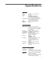
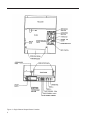
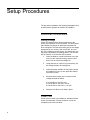
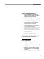
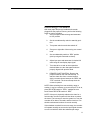
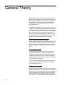
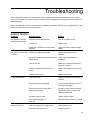
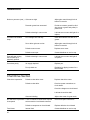
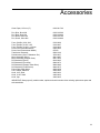
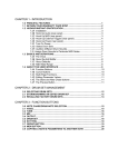
OMEGA
Model 156
Strip Chart Recorder
User’s Manual
0115-0196 • 11/4/99
Table of Contents
Introduction..........................................................................................................................................................3
Unpacking ..........................................................................................................................................................4
Specifications ......................................................................................................................................................5
General ........................................................................................................................................................5
Servo System ..............................................................................................................................................5
Chart Drive System ......................................................................................................................................5
Setup Procedures................................................................................................................................................8
Electrical Connections ..................................................................................................................................8
Setting Voltage ......................................................................................................................................8
Power Cord ............................................................................................................................................8
Chart Paper Installation ................................................................................................................................9
Pen Installation ............................................................................................................................................9
Grounding ..................................................................................................................................................10
Input Signal Connections............................................................................................................................10
Recording Procedure ..................................................................................................................................11
General Theory ................................................................................................................................................12
Power Supply..............................................................................................................................................12
Pen Drive System ......................................................................................................................................12
Chart Drive System ....................................................................................................................................12
Calibration Procedures......................................................................................................................................14
Power Supply..............................................................................................................................................14
Pen Drive System ......................................................................................................................................14
Chart Drive System ....................................................................................................................................14
Gain ......................................................................................................................................................14
Offset ....................................................................................................................................................15
Span ....................................................................................................................................................16
Special Features ..............................................................................................................................................18
Remote Chart Control ................................................................................................................................18
Remote Chart Programming/TTL ..............................................................................................................18
Operational Tips and Maintenance ..................................................................................................................20
Troubleshooting ................................................................................................................................................21
Analog Section............................................................................................................................................21
Chart Drive Section ....................................................................................................................................22
Accessories ......................................................................................................................................................23
2
Introduction
The dc analog recorder is an application of advanced
electronic techniques. Its solid state modular circuitry
yields high performance and reliability.
This graphic recorder may be used in many different
applications in the medical, teaching and industrial fields
where a precision instrument is of utmost importance.
Measurement of dc voltage, current, temperature and a
variety of other variables are made possible with the use
of these recorders.
3
Unpacking
Remove the packing list and verify that you have received
all equipment. If you have any questions about the shipment, please call the OMEGA Customer Service
Department.
When you receive the shipment, inspect the container
and equipment for any signs of damage. Note any evidence of rough handling in transit. Immediately report any
damage to the shipping agent.
NOTE: The carrier will not honor any claims unless all
shipping material is saved for their examination. After
examining and removing contents, save packing material
and carton in the event reshipment is necessary.
If the recorder fails to operate properly, check all connections, cables and fuses. Ensure that all plug-in boards are
firmly seated in place. Double-check for “pilot error”
before calling the factory.
DO NOT RETURN RECORDERS FOR FACTORY
WARRANTY SERVICE WITHOUT SPECIFIC
AUTHORIZATION.
4
Specifications
General
Power:
Wattage:
Fuse:
Writing Method:
Chart:
Dimensions:
Weight:
120/240 VAC + 10%, 50/60 Hz
15 Watts
3AG Slo-Blo 0.3A @ 120V
3AG Slo-Blo 0.15A @ 240V or
Two 5 x 20 Slo-Blo 0.16A @ 240V
Pens are disposable fiber tipped units
with self-contained ink supply.
125 mm width; 30 meter length
5.0” H x 10.8” W x 11.5” D
8.0 lb.
Servo System
Span-Full Scale: 1mV, 2mV, 5mV, 10mV, 20mV,
50mV, 100mV, 500mV, 1V, 2V and 5V
(10mV through 50V with uncalibrated
10:1 attenuator)
Input Type:
Floating (±100V single ended)
Input Impedance: 2.5 Megohms, 1mV to 5V ranges
Pen Response: Less than 50 cm/sec
Damping:
Critically damped on all ranges
(requires no adjustment)
Accuracy:
Linearity:
±5%
Deadband:
±0.1%
Repeatability: ±0.1%
Zero Adjust:
Continuously adjustable from -100%
to +100% (full scale +100%
suppression) Right hand zero is
standard
Normal Mode:
35 db Typical @ 3Hz, 100 Volts
Maximum
Rejection:
Begins filtering @ 3Hz, 100 Volts
maximum
Chart Drive System
Chart Drive:
Chart Speeds:
Chart Speed
Accuracy:
Control:
Stepper Motor
1,2,3,4,5,6,10,12,15,20 and 30 cm per
minute and per hour, switch selectable
Less than 0.03% error - typical 0.02%
Internal: crystal oscillator
External: remote pulse train,TTL/CMOS
or contact closure for start/stop
5
Figure 1: Single Channel Output/Control Location
6
Figure 2: Power Entry Module Voltage Selector
7
Setup Procedures
The procedures detailed in the following paragraphs must
be performed to prepare the recorder for operation.
Electrical Connections
Setting Voltage
Check the voltage selector block located next to the
power cord connector on the rear panel. The white plastic
tab indicates the voltage for which the instrument has
been configured. This has been factory set for the voltage
appropriate to your country (120 or 240 VAC; 50 or 60
Hz). If the voltage is incorrectly set, you should reset it to
the proper value before proceeding further. The recorder
will not function in 100 and 220 VAC positions.
1. Insert the blade of a small screwdriver in the slot
next to to the connector and pry open the fuse
block. Pull the fuse block straight out.
2.
Using tweezers or a pair of long nose pliers, pull
the voltage selector card straight out.
3.
Orient the plastic indicator for the proper voltage
as indicated in Figure 2, then press the selector
card back in place.
4.
Ensure that the proper fuse is inserted for the
voltage selected as follows:
0.3A Slo-Blo for 120 VAC and
0.15A Slo-Blo for 240 VAC, 3AG or
0.16A Slo-Blo for 240 VAC, 5 x 20 mm
5.
Snap the fuse block cover back in place.
Power Cord
Power to the recorder is provided by a standard modular
power cord assembly. Connect the power cord to the
receptacle next to the fuse block.
8
SETUP PROCEDURES
Chart Paper Installation
1.
Remove masking tape from the roll of chart
paper and cut or tear each side to form a blunt
point at the center. (DO NOT FOLD.)
2.
Pull the knob on the chart paper core support,
located on the rear panel of the recorder. Install
paper, making sure its seats evenly on the two
core supports. Release knob.
3.
Lift the pen lift lever (on the left side of the
instrument) to the full upright position.
4.
Manually feed the pointed paper under the pen
cover and across the writing area.
5.
Install the paper under the paper hold down and
across the paper sprockets, making sure the
holes in the paper align evenly on the sprockets.
6.
Lower the pen lift lever.
7.
The paper is now ready for operation.
NOTE: After manual advancement or rewind there may
be a short delay, depending on chart speed selected.
Then the chart will run at the selected speed.
Pen Installation
1.
Lift the pen lift lever to the full up position.
2.
Remove the pen cap and store it where it can
easily be found. Pens can be left uncapped for
long periods of time, but greater pen life results
from capping when not in use.
3.
Slide the pen into the pen carriage and gently
push back until the nib is firmly seated against
the carriage.
4.
Return the pen lift lever to the full down position.
9
SETUP PROCEDURES
Grounding
For best performance, the green (or green and yellow)
ground wire in the power cord for the recorder and the
signal source should share a common water pipe ground.
The green (green and yellow) wire in the power cord is
connected to the recorder ground (chassis), but not to the
signal input. If the signal input does not have a third wire
in its power cord, or if the instrument is not grounded,
connect a wire between the recorder ground (green terminal) and the chassis of the signal source.
In case of large normal-mode signals, particularly 120 Hz,
connect the recorder ground (green terminal) to the
source of the normal-mode signal, or to the negative
recorder input (black terminal).
Input Signal Connections
This instrument requires a dc voltage input. Signal
sources with current outputs will require a shunt resistor
across the + (red) and - (black) inputs. Ohms law may be
used to compute the proper value for a given input range.
The formula is:
R = E
I
Where: E is the recorder span range selected in volts.
I is the maximum current signal to be recorded
in amps.
R is the resistance of the shunt resistor in Ohms.
Electrical connections are made as follows:
Signal source positive to recorder red (+)
terminal.
Signal source negative to recorder black (-)
terminal.
Right hand chart zero is standard on the recorder.
Positive going signals drive the pen to the left. If an opposite presentation is desired, reverse the input leads and
use the zero adjust control to position the pen to the
opposite side of the chart. Negative signals will now drive
the pen to the right.
NOTE: This unit is calibrated for right hand zero. Reversal
of the input leads may yield a ±3% full scale error.
10
SETUP PROCEDURES
Recording Procedure
With chart paper and pen(s) installed and recorder
plugged into the proper ac source, perform the following
steps for routine recording.
1. Set input span to desired range and attenuator
to CAL position.
2.
Set the record/stand-by switch to stand-by position.
3.
Turn power switch on and chart switch off.
4.
Zero pen to right side of chart using zero control
knob.
5.
Set record/stand-by switch to “REC” position
(with input signal connected as above).
6.
Adjust input span and attenuator for desired full
scale range to best display input signal.
7.
Turn chart drive on and set chart speed as
desired. Make sure the chart paper holes are
properly aligned with sprocket teeth.
8.
REMOTE CHART CONTROL: Remove the
jumper located on the rear terminal strip. To
start the chart drive from a remote location,
apply a contact closure between the “REM” and
“LOC” terminals. The chart will stop when the
contact is opened.
NOTE: When switching from one sensitivity range to
another, it may be necessary to re-zero the pen. To do so,
place REC/STBY switch in “STBY,” readjust the zero
knob. Return REC/STBY switch to “REC.”
NOTE: If the pen is physically stalled on the chart for a
few seconds, the servo system will shut down to protect
the motor. The best way to reset the system is to turn the
recorder off for about 5 seconds, and then back on. Pen
should reactivate and continue to record normally.
If the shutdown resulted from an over-range, the recorder
will operate normally as soon as the input signal decreases to a level which is within the selected span range.
11
General Theory
The dc input signal to the recorder is first filtered, then
amplified by the pre-amp to a level which is less susceptible to noise and interference. This conditioned signal is
then applied to the servo amplifier which continuously
compares it to the feedback signal developed by the
servo potentiometer,
The difference between these two signals is a positive or
negative error signal that is amplified and use to drive the
servo motor, which is coupled to the servo potentiometer,
in a direction as to reduce the error signal to zero. Since
the recorder plate pen is mechanically coupled to the
servo motor and servo potentiometer, its position on the
chart represents an accurate and continuous permanent
graphic record of the input signal. (See Figure 3.)
Chart Recorder Power Supply
Ac line voltage is reduced by step-down transformers and
converted to dc by solid state rectifiers and regulators. A
stable dc voltage, generated by a temperature compensated zener diode, is used as 0 reference for the servo
pot.
Pen Drive System
A dc servo motor is used to control the servo pot and
recorder pen by means of a gear driven servo drum
assembly. The pen is attached to a drive cable which is
wrapped around and secured to the drum. As the drum
rotates, the pen is moved across the chart proportionate
to the amount of drum rotation.
The recorder uses OMEGA’s patented pulse modulated
servo to achieve greater accuracy and less deadband
than conventionally driven.
Chart Drive System
In this simple, reliable system an internal crystal oscillator
generates pulses which are divided down by integrated
circuit logic. The chart speed switch selects the appropriate pulse rate to drive the stepper motor at the desired
speed. (Since the crystal frequency is not a function of
line frequency, chart speeds are completely independent.)
12
GENERAL THEORY
Figure 3: Basic Recorder Block Diagram
13
Calibration Procedures
This recorder is designed to be simple, reliable, easy to
maintain and repair. Therefore, the procedures presented
here will be as simple, clear and brief as possible. For
special problems, we recommend that you contact your
local representative or the factory service department.
Chart Recorder Power Supply
There are no calibration adjustments in the power supply.
Barring failure, the reference voltages will remain constant and stable.
Chart Drive System
The stepper drive printed circuit board has no calibration
adjustments. Barring failure or gear binding, the stepper
drive printed circuit board and stepper motor should give
many years of reliable service. If a problem should arise,
consult your local representative or factory service department.
Pen Drive System
The calibrations covered in this section should be performed by a qualified technician. The technician must
have knowledge of working around voltages which may
cause an electrical shock.
NOTE: Gain, offset and span must be adjusted for each
channel in multi-pen units.
Gain (see Figure 4.)
The gain adjustment controls the servo loop gain or “dead
band” of the recorder. This can be reached through the
hole in the bottom of the recorder marked GAIN. If set too
high, the pen will “buzz.” If set too low, the pen will be
sluggish.
TO CALIBRATE:
A. Short (+) and (-) inputs, (red and black connectors on back of recorder) and set pen to center
scale by tuning the zero control.
B.
14
Adjust gain control clockwise until pen “buzzes,”
then back off counterclockwise until buzzing
stops.
CALIBRATION PROCEDURES
C.
Recheck the adjustment by moving the pen to
full scale and back using the zero control. If pen
“buzzes” at any point, turn gain counterclockwise until the “buzzing” stops.
Offset
This adjustment reduces the zero shift between input
spans to minimum value. Performance of this adjustment
requires the recorder input to be switched between a
short circuit and a 50K ohm resistor. Connect a 50K resistor across the recorders input binding posts (+and -).
1. Allow the recorder to warm up to operating temperature (30 minutes is suggested).
2.
Remove the chassis wrap of the recorder.
3.
Place REC/STBY switch in STBY.
4.
PLace the range (span) switch in the 100 mV
setting.
5.
Use the zero adjust knob to set the pen to midscale.
6.
Switch the range switch to the 1mV position.
7.
Return the pen to the setting in step “E” with the
E potentiometer in the pre-amp circuit. (Figure
4.)
8.
Place the REC/STBY switch in REC.
9.
Return the pen to the setting in step “E” with the
1 potentiometer in the pre-amp circuit. (Figure
4.)
10. These adjustments are interactive so it will be
necessary to repeat steps 3-9 until minimum
pen movement is achieved.
11. Remove the 50K resistor.
15
CALIBRATION PROCEDURES
Span (See Figure 4.)
This adjustment enables the technician to adjust the
recorder so that a calibrated full scale input signal will
move the pen to the full width of the chart. The first span
adjustment can be reached through a hole in the bottom
of the recorder marked SPAN. The second span adjustment is normally not necessary and the bottom panel
must be removed to gain access to this adjustment.
TO CALIBRATE:
1. Allow the recorder to warm up to operating temperature. (30 minutes is suggested.)
16
2.
Set the recorder to the 1 mV position and the
signal source to zero output.
3.
Carefully set the pen to zero by turning the zero
control on the recorder control panel.
4.
Apply a 0.1% accuracy 1 mV dc signal to the
input.
5.
Insert a screwdriver in the hole in the bottom of
the recorder marked SPAN. Move the adjustment until the the pen is at the 100% position.
6.
Check all input spans with proper inputs for
100% +0.5% deflection. Check the zero in all
ranges and reset as necessary.
CALIBRATION PROCEDURES
NOTE: If the spans for the ranges from 200mV through
5V DO NOT deflect 100% + 0.5%, continue with the following steps:
G. Remove the Chassis wrap (Figure 4).
H.
Set the range (span) switch to the 1V position.
Check the zero and reset as necessary.
I.
Apply a 1V 0.1% accuracy dc signal to the input.
J.
Adjust the 500 mV/1/2/5V range calibration
potentiometer located on pre-amp PCB (See
Figure 4) for 100% + 0.5% pen deflection.
K.
Check all inputs from 200mV to 5V with proper
inputs for 100% +5% pen deflection.
There are no additional calibration points on the recorder.
Figure 4: Bottom COver Mounting Screw and Gain/Span Control Access Location
17
Special Features
Remote Chart Control
The remote chart control provides the ability to turn the
chart drive on and off from a remote location when a contact closure is made between terminals “REM” and “LOC”
of the terminal strip on the rear panel. This feature is
standard.
Remote Chart Programming/TTL
The recorder chart drive system is designed to operate
from an external frequency source (including TTL levels).
The chart can be run at time rates other than those built
in the recorder. This mode is obtained by applying a pulse
train (see below) to the “REM” terminal and the “COM”
terminal on the rear panel terminal strip.
NOTE: The jumper between the “REM” and the “LOC” terminal must be removed for this programming.
PULSE TRAIN SPECIFICATIONS:
0 (Lo) state voltage +0.5V or less
1 (HI) state voltage +3V to 10 volts maximum
Minimum pulse width: 100 microseconds
Pulse frequencies up to 10 K Hz may be used providing
the chart speed selector is set to limit actual chart movement to 50 cm/min or less. A 50 cm/min paper speed can
be obtained by applying a 250 Hz external frequency and
setting the chart selector switch in the 30 cm/min. position.
The formula is Chart Speed =
Where:
FxS
150 Hz
F = external frequency in HZ
S = Selected chart speed
When the external frequency is set to 150 Hz, the chart
drive will run at the speeds marked on the top panel
selector switch.
If the external is increased (or decreased) by 10% of
standard 150 Hz rate, the actual chart speed will be 10%
faster (or slower in the case of a decrease) than the setting on the panel selector switch.
18
SPECIAL FEATURES
EXAMPLE: The selector switch is set at 30 cm/min and
the external frequency changed to 165 Hz (a 10%
increase). The chart will now run at 33 cm/min.
NOTE: Changes of external frequency affect all selector
speeds by the same factor.
The recommended maximum chart speed for start-stop
operation is 50 cm/mi. If the frequency is “swept” (no
start-stop), it is possible to run faster than 50 cm/min;
however, sweep rates must be gradual enough to assure
accurate mechanical tracking.
19
Operational Tips and
Maintenance
Chart paper and pens have been carefully matched for
optimum writing and minimum “bleed.” Substitutions could
cause improper writing. Keep pen tips covered when not
in use to prolong writing life.
NOTE: If the pen is left uncapped for long periods of time
and dries out, it may be revitalized by dipping in water for
a few seconds.
Allow the recorder to warm up for about 30 minutes if
high accuracy/stability recording is desired.
Firm tension on the paper roll and correct alignment of
the chart paper holes on the sprocket teeth are required
for proper chart paper feed.
The exterior surfaces of the recorder should be cleaned
periodically by wiping with a soft damp cloth. Water may
be used to remove ink, etc.; however, solvents should not
be used as they may damage or destroy the finish.
20
Troubleshooting
The modularity and simplicity of this recorder make it possible to isolate the problem area in many cases.
Once you have done this, a quick call to our Customer Service Department will bring you needed advice or a
replacement part.
While it is impossible to think of every problem possibility, the following chart will give you suggestions on how
to solve the most common recorder problems.
Analog Section
Symptom
Probable Cause
Remedy
Pilot light does not light,
and recorder is inactive.
Ac power source disconnected.
Connect ac power source.
Fuse blown.
Replace fuse.
Power entry module has wrong voltage
selected.
Check power entry module voltage
setting.
Signal input leads disconnected.
Check input leads on rear of
recorder.
Pilot light on, but recorder
is inactive.
Pre-amp/servo driver interconnect harness Check interconnect harness
disconnected.
installation.
Excessive deadband.
Noise on pen trace.
Gain set too low.
Adjust gain control through hole in
bottom of recorder.
Defective pre-amp/servo driver circuit
board.
Replace pre-amp/servo driver circuit
board.
Defective servo motor.
Replace servo motor.
Gain set too low.
Adjust gain control hole in bottom of
recorder.
Excessive normal mode signal.
Connect ground terminal to source
of normal mode signal.
Recorder ground not connected to
signal source ground.
Provide a common ground for third
for third wire (green or green and
yellow) in power cord.
Pen drive cable to loose.
Tighten pen drive cable.
Pen carriage dragging on
slide rod.
Lubricate slide rod with oil or grease.
Noisy input signal from signal source.
Check signal source.
Extremely noisy power line.
Check power line.
21
TROUBLESHOOTING
Noise on pen trace (cont.) Gain set too high.
Adjust gain control through hole in
bottom of recorder.
Recorder ground not connected.
Provide a common ground for third
wire (green or green and yellow) in
power cord.
Defective bearing in servo motor.
Lubricate servo motor with light oil or
replace.
Pen carriage slide rod dirty.
Clean and lubricate rod with oil or
grease.
Servo driver gain set too low.
Adjust gain control through hole in
bottom of recorder.
Defective servo motor.
Replace servo motor.
Defective servo pot.
Contact distributor or service rep.
Pens will stop moving
but will catch up if
physically pushed.
Defective bearing in servo motor.
Lubricate servo motor with light oil
or replace.
Pen writes poorly.
Ink supply depleted.
Replace pen.
Pen tip dried out.
Revitalize by dipping in water for a
few seconds.
Pen trace has isolated
steps.
Chart Drive Section
Chart drive inoperative.
Defective chart drive motor.
Replace chart drive motor.
Defective chart drive.
Check ac power connections to
circuit board.
Check dc voltages on circuit board.
Lubricate chart drive shaft.
Gear train binding.
No chart drive in particular Loose or defective connections at speed
chart speed.
selector and/or circuit board connector.
Fuse blows.
22
Adjust chart motor for gear mesh.
Check and repair connections.
Defective component on circuit board.
Replace defective circuit board.
Internal fault.
Contact distributor or service rep
Accessories
Chart Paper, 125 mm (5”)
0100-0017-06
Pen,
Pen,
Pen,
Pen,
0100-0105-06
0100-0106-06
0100-0107-06
0100-0108-06
Blue, Short Nib
Red, Short Nib
Black, Short Nib
Green, Short Nib
Fuse, (Slo-Blo) 0.3A, 3AG
Fuse, (Slo-Blo) 0.15A, 3 AG
Fuse, (Slo-Blo) 0.16A, 5 x 20 mm
Power Cord (Standard Model)
Power Cord (International Model)
Transformer Assembly
Potentiometer (Servo, Rebalance Pot)
Motor Assembly (Servo)
Motor Assembly (Stepper Chart)
PCB Assembly (Servo)
PCB Assembly (Pre-Amp)
PCB Assembly (Stepper Chart Drive)
PCB Assembly (Chart Select)
Pinion Gear-Chart Motor
Feet, Rubber, Adhesive
Knob, 0.25” Shaft
Knob, 0.125” Shaft
Knob, Cap
5120-0006
5120-0007
5120-0033
6040-0005
CRX70
9500-0140
4750-0037
9501-6097
9501-3255
9816-0045
9800-0073
9800-0080
9800-0075
9050-0259
2850-0005
2405-0033
2405-0032
2405-0035
IMPORTANT: Always specify model number, options and serial number when ordering replacement parts and
sub-assemblies.
23
WARRANTY/DISCLAIMER
OMEGA ENGINEERING, INC. warrants this unit to be free of defects in materials and workmanship for a period of 13
months from date of purchase. OMEGA Warranty adds an additional one (1) month grace period to the normal one (1)
year product warranty to cover handling and shipping time. This ensures that OMEGA’s customers receive maximum
coverage on each product.
If the unit should malfunction, it must be returned to the factory for evaluation. OMEGA’s Customer Service Department
will issue an Authorized Return (AR) number immediately upon phone or written request. Upon examination by OMEGA, if
the unit is found to be defective it will be repaired or replaced at no charge. OMEGA’s WARRANTY does not apply to
defects resulting from any action of the purchaser, including but not limited to mishandling, improper interfacing, operation
outside of design limits, improper repair, or unauthorized modification. This WARRANTY is VOID if the unit shows evidence of having been tampered with or shows evidence of of being damaged as a result of excessive corrosion; or current, heat, moisture or vibration; improper specification; misapplication; misuse or other operating conditions outside of
OMEGA’s control. Components which wear are not warranted, including but not limited to contact points, fuses and
triacs.
OMEGA is pleased to offer suggestions on the use of its various products. However, OMEGA neither assumes
responsibility for any omissions or errors nor assumes liability for any damages that result from the use of its
products in accordance with information provided by OMEGA, either verbal or written. OMEGA warrants only that
the parts manufactured by it will be as specified and free of defects. OMEGA MAKES NO OTHER WARRANTIES
OR REPRESENTATIONS OF ANY KIND WHATSOEVER, EXPRESSED OR IMPLIED, EXCEPT THAT OF TITLE, AND
ALL IMPLIED WARRANTIES INCLUDING ANY WARRANTY OF MERCHANTIBILITY AND FITNESS FOR A PARTICULAR PURPOSE ARE HEREBY DISCLAIMED. LIMITATION OF LIABILITY: The remedies of purchaser set forth herein are exclusive and the total liability of OMEGA with respect to this order, whether based on contract, warranty,
negligence, indemnification, strict liability or otherwise, shall not exceed the purchase price of the component
upon which liability is based. In no event shall OMEGA be liable for consequential, incidental or special damages.
CONDITIONS: Equipment sold by OMEGA is not intended to be used, nor shall it be used: (1) as a “Basic Component”
under 10 CFR 21 (NRC), used in or with any nuclear installation or activity; or (2) in medical applications or used on
humans. Should any Product(s) be used in or with any nuclear installation or activity, medical application, used on
humans, or misused in any way, OMEGA assumes no responsibility as set forth in our basic WARRANTY/DISCLAIMER
language, and additionally, purchaser will indemnify OMEGA and hold OMEGA harmless from any liability or damage
whatsoever arising out of the use of the Product(s) in such a manner.
RETURN REQUESTS/INQUIRIES
Direct all warranty and repair requests/inquiries to the OMEGA Customer Service Department. BEFORE RETURNING
ANY PRODUCT(S) TO OMEGA, PURCHASER MUST OBTAIN AN AUTHORIZED RETURN (AR) NUMBER FROM
OMEGA’S CUSTOMER SERVICE DEPARTMENT (IN ORDER TO AVOID PROCESSING DELAYS). The assigned AR
number should then be marked on the outside of the return package and on any correspondence.
The purchaser is responsible for shipping charges, freight, insurance and proper packaging to prevent breakage in transit.
For WARRANTY RETURNS, please have the
following information available BEFORE contacting
OMEGA:
1. P.O.number under which the product was
PURCHASED,
2. Model and serial number of the product under
warranty, and
3. Repair instructions and/or specific problems
relative to the product.
For NON-WARRANTY REPAIRS, consult OMEGA
for current repair charges. Have the following information
available BEFORE contacting OMEGA:
1. P.O. number to cover the COST of the repair,
2. Model and serial number of product, and
3. Repair instructions and/or specific problems relative to
the product.
OMEGA’s policy is to make running changes, not model changes, whenever an improvement is possible. This affords our
customers the latest in technology and engineering.
OMEGA is a registered trademark of OMEGA ENGINEERING,INC.