1
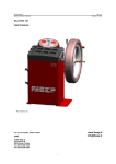
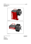
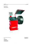
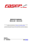
Fasep 2000 srl
Videotronic Omega: User’s Manual
Rev. 1.3
November 24, 2004
VIDEOTRONIC
USER’S MANUAL
www.fasep.it
[email protected]
For any information, please contact:
e-mail:
FASEP 2000 srl
Via Faentina 96
50030 Ronta (Fi) Italy
Tel. #39 055 840 3126
Fax #39 055 840 3354
i
Fasep 2000 srl
Videotronic Omega: User’s Manual
Rev. 1.3
November 24, 2004
WARNING
.This document contains information which is the property of FASEP 2000 rl and all rights are reserved. This manual shall not be
photocopied or reproduced in any way without the prior written consent of FASEP 2000 srl.
.FASEP 2000 srl reserves the right to revise products firmware, software or documentation without obligation to notify any person
or organization. The information contained in this document is subject to change without warning.
.Prior of the installation of the unit described in this manual, user should read this manual carefully to be instructed properly on
installation, use and maintenance of the unit.
.Failing to read this manual and operate accordingly may cause damage to the user or the unit.
.FASEP 2000 srl shall not be responsible for inconvenience, breakdown, accidents due to uncomplete knowledge of this manual
or uncomplete application of raccomendations described in this manual.
.FASP 2000 srl shall not be responsible for inconvenience, breakdown, accidents due to unauthorized modifications of the unit,
use of non-original or unauthorized accessories (see Accessories listing in this manual for a list of original accessories available
for this model).
.FASEP 2000 srl shall not be responsible for any inconvenience, breakdown, accidents caused directly or indirectly by not
qualified service. Service to any parts by not qualified persons will void warranty and will void any right of the owner of the
unit.
SYMBOLS AND CONVENTIONS
To speed the retrieval of main information and make easy to understand the instructions, this manual uses the following typing
conventions:
<NAME OF THE PUSH BUTTON>
Used to indicate name of push-buttons on the control panel.
DISPLAY
Used to indicate text or number visible on the displays on the control panel.
J
ADVICES
Contain useful advices or solutions, evidence d with respect to the rest of the text.
G
NOTE
Notes contain important information, evidenced to the rest of the text.
I
WARNING
Warning messages appears corresponding to procedures that, if not properly observed,
may lead to loose of data or cause damage to the unit.
!
CAUTION
Caution messages appears corresponding to procedures that, if not properly observed,
may cause injuries to the user.
ii
Fasep 2000 srl
Videotronic Omega: User’s Manual
Rev. 1.3
November 24, 2004
TABLE OF CONTENTS
WARNING . . . . . . . . . . . . . . . . . . . . . . . . . . . . . . . . . . . . . . . . . . . . . . . . . . . . . . . . . . . . . . . . . . . . . . . . . . . . . . . . . . . . ii
SYMBOLS AND CONVENTIONS . . . . . . . . . . . . . . . . . . . . . . . . . . . . . . . . . . . . . . . . . . . . . . . . . . . . . . . . . . . . . . . . . . . . ii
TABLE OF CONTENTS . . . . . . . . . . . . . . . . . . . . . . . . . . . . . . . . . . . . . . . . . . . . . . . . . . . . . . . . . . . . . . . . . . . . . . . . . . iii
1
PRESENTATION . . . . . . . . . . . . . . . . . . . . . . . . . . . . . . . . . . . . . . . . . . . . . . . . . . . . . . . . . . . . . . . . . . . . . . 1-1
1.0
Intended Use . . . . . . . . . . . . . . . . . . . . . . . . . . . . . . . . . . . . . . . . . . . . . . . . . . . . . . . . . . . . . . . . . 1-1
2
INSTALLATION . . . . . . . . . . . . . . . . . . . . . . . . . .
2.1
Moving the unit . . . . . . . . . . . . . . . . . . .
2.2
Assembling the unit . . . . . . . . . . . . . . . .
2.3
Installation . . . . . . . . . . . . . . . . . . . . . .
2.4
Electrical Hookup . . . . . . . . . . . . . . . . .
2.5
Compressed air Hookup (PL models only)
3
CALIBRATION OF WHEEL BALANCER . . . . . . . . . . . . . . . . . . . . . . . . . . . . . . . . . . . . . . . . . . . . . . . . . . . . . . 3-1
3.1
How to calibrate the wheel balancer . . . . . . . . . . . . . . . . . . . . . . . . . . . . . . . . . . . . . . . . . . . . . . . . . 3-1
3.2
How to control the calibration of wheel balancer and position weight . . . . . . . . . . . . . . . . . . . . . . . . . . 3-1
4
MEASUREMENT AND CORRECTION OF UMBALANCE . . . . . . . . . . .
4.1
Placing the wheel rim on the wheel balancer . . . . . . . . . . . .
4.2
Input of Rim Dimensions (standard version) . . . . . . . . . . . . .
4.3
Input of Rim Dimensions (external measuring system version)
4.4
Input of Rim Dimensions (ALU-SE or LASER version) . . . . .
4.5
Detecting and correcting umbalance . . . . . . . . . . . . . . . . . .
5
HOW TO OPTIMIZE UMBALANCE OF THE WHEEL . . . . . . . . . . . . . . . . . . . . . . . . . . . . . . . . . . . . . . . . . . . . . 5-1
6
SPECIAL FUNCTIONS . . . . . . . . .
6.1
Language selection . . . .
6.2
Setup . . . . . . . . . . . . . .
6.3
Personalization . . . . . . .
6.4
Run-out check program .
6.5
Planarity check program
.
.
.
.
.
.
.
.
.
.
.
.
.
.
.
.
.
.
.
.
.
.
.
.
.
.
.
.
.
.
.
.
.
.
.
.
.
.
.
.
.
.
.
.
.
.
.
.
.
.
.
.
.
.
.
.
.
.
.
.
.
.
.
.
.
.
.
.
.
.
.
.
.
.
.
.
.
.
.
.
.
.
.
.
.
.
.
.
.
.
.
.
.
.
.
.
.
.
.
.
.
.
.
.
.
.
.
.
.
.
.
.
.
.
.
.
.
.
.
.
.
.
.
.
.
.
.
.
.
.
.
.
.
.
.
.
.
.
.
.
.
.
.
.
.
.
.
.
.
.
.
.
.
.
.
.
.
.
.
.
.
.
.
.
.
.
.
.
.
.
.
.
.
.
.
.
.
.
.
.
.
.
.
.
.
.
.
.
.
.
.
.
.
.
.
.
.
.
.
.
.
.
.
.
.
.
.
.
.
.
.
.
.
.
.
.
.
.
.
.
.
.
.
.
.
.
.
.
.
.
.
.
.
.
.
.
.
.
.
.
.
.
.
.
.
.
.
.
.
.
.
.
.
.
.
.
.
.
.
.
.
.
.
.
.
.
.
.
.
.
.
.
.
.
.
.
.
.
.
.
.
.
.
.
.
.
.
.
.
.
.
.
.
.
.
.
.
.
.
.
.
.
.
.
.
.
.
.
.
.
.
.
.
.
.
.
.
.
.
.
.
.
.
.
.
.
.
.
.
.
.
.
.
.
.
.
.
.
.
.
.
.
.
.
.
.
.
.
.
.
.
.
.
.
.
.
.
.
.
.
.
.
.
.
.
.
.
.
.
.
.
.
.
.
.
.
.
.
.
.
.
.
.
.
.
.
.
.
.
.
.
.
.
.
.
.
.
.
.
.
.
.
.
.
.
.
.
.
.
.
.
.
.
.
.
.
.
.
.
.
.
.
.
.
.
.
.
.
.
.
.
.
.
.
.
.
.
.
.
.
.
.
.
.
.
.
.
.
.
.
.
.
.
.
.
.
.
.
.
.
.
.
.
.
.
.
.
.
.
.
.
.
.
.
.
.
.
.
.
.
.
.
.
.
.
.
.
.
.
.
.
.
.
.
.
.
.
.
.
.
.
.
.
.
.
.
.
.
.
.
.
.
.
.
.
.
.
.
.
.
.
.
.
.
.
.
.
.
.
.
.
.
.
.
.
.
.
.
.
.
.
.
.
.
.
.
.
.
.
.
.
.
.
.
.
.
.
.
.
.
.
.
.
.
.
.
.
.
.
.
.
.
.
.
.
.
.
.
.
.
.
.
.
.
.
.
.
.
.
.
.
.
.
.
.
.
.
.
.
.
.
.
.
.
.
.
.
.
.
.
.
.
.
.
.
.
.
.
.
.
.
.
.
.
.
.
.
.
.
.
.
.
.
.
.
.
.
.
.
.
.
.
.
.
.
.
.
.
.
.
.
.
.
.
.
.
.
.
.
.
.
.
.
.
.
.
.
.
.
.
.
.
.
.
.
.
.
.
.
.
.
.
.
.
.
.
.
.
.
.
.
.
.
.
.
.
.
.
.
.
.
.
.
.
.
.
.
.
.
.
.
.
.
.
.
.
.
.
.
.
.
.
.
.
.
.
.
.
.
.
.
.
.
.
.
.
.
.
.
.
.
.
.
.
.
.
.
.
.
.
.
.
.
.
.
.
.
.
.
.
.
.
.
.
.
.
.
.
.
.
.
.
.
.
.
.
.
.
.
.
.
.
.
.
.
.
.
.
.
.
.
.
.
.
.
.
.
.
2-1
2-1
2-1
2-1
2-1
2-2
4-1
4-1
4-1
4-1
4-2
4-2
6-1
6-1
6-1
6-1
6-1
6-1
APPENDIX . . . . . . . . . . . . . . . . . . . . . . . . . . . . . . . . . . . . . . . . . . . . . . . . . . . . . . . . . . . . . . . . . . . . . . . . . . . . . . . . A-1
A:
B:
Technical data . . . . . . . . . . . . . . . . . . . . . . . . . . . . . . . . . . . . . . . . . . . . . . . . . . . . . . . . . . . . . . . . A-1
Environmental Data, Safety Features and Requirements . . . . . . . . . . . . . . . . . . . . . . . . . . . . . . . . . . . . . . . . . . B-2
iii
Fasep 2000 srl
Videotronic Omega: User’s Manual
Rev. 1.3
November 24, 2004
1
PRESENTATION
1.0
Intended Use
This unit is designed to measure and correct static and dynamic unbalance of vehicle wheel, the dimension and weight of
which are within the working range of the machine (see “Technical Data”appendix for reference)
This unit is meant for a professional use. Operator shall be properly trained before use. Training Course is not included
in the price of the unit and must be purchased separately.
This unit is designed for indoor use only ( see “Environmental Data”appendix for reference).
!
CAUTION:
2
INSTALLATION
2.1
Moving the unit
I
WARNING
This unit is designed to spin vehicle wheels only, within the range of dimensions and weight
approved (see “Technical Data”appendix for reference). Special adaptors suit this purpose. Do not
attempt to use the machine to spin anything else. Unproper locking may cause the part being
spinned to be ejected, causing damage to the unit itself, the operator or anything in the in the
neighboorhood.
When the unit has to be moved: never lift
balancer by motor shaft or by neighborhood of it.
2.2
Assembling the unit
For ease of transportation, the wheel balancer might be disassembled
into units. If necessary, assembling instruction are provided within each
package.
2.3
Installation
The wheel balancer must be installed on a firm and level ground.
G
NOTE:
the machine must be secured to the floor. Using four holes
in the base and anchor bolts provided.
2.4
Electrical Hookup
!
CAUTION:
2.4.1
Electrical hookup is to be provided by a qualified electrician.
2.4.2
A fusible wall-mounted switchbox is required at the installation site. This switch should provide on-off control and overload
protection for your wheel balancer only. The switchbox should be fused with time-delay fuse(s) in accordance with the
power rating specified on your wheel balancer.
2.4.3
Electrical connection of the machine should be by plug connectors.
2.4.4
The balancer must be effectively connected to ground. The electric cord is regularly provided with a ground terminal.
2.4.5
Make sure that Power Rate Specifications for your wheel balancer (refer to nameplate on the wheel balancer) comply with
those provided by the external power source.
!
CAUTION
Failure to follow these instructions can results in
damage to unit or create an electrical hazard and
will void warranty.
After electrical hookup has been performed unit is ready to operate. Always observe pertinent
safety precautions when operating the unit (see Appendix tables for an overview of relevant Safety
requirement).
2-1
Fasep 2000 srl
Videotronic Omega: User’s Manual
2.5
!
2.5.1
Rev. 1.3
November 24, 2004
Compressed air Hookup (PL models only)
CAUTION
Failure to follow these instructions can result in damage to unit or create a hazard and will void warranty.
1.
Compressed Air hookup is to be provided by a qualified technician, under the local safety
requirements, in line with relevant national standards and regulations. All fitting and hoses must
conform to local codes.
2.
A wall-mounted lubricator and water-separator is required at the installation site.
3.
Compressed Air circuit to the balancer shall be regulated to a maximum pressure of 7 atm.
Overpressure could compromise cylinder operation.
CONNECT TO AIR SUPPLY:
The machine is fitted with a universal connector and therefore no other special or additional fitting is required. Push all the
way onto the connector a high pressure rubber air-hose and secure it.
2-2
Fasep 2000 srl
Videotronic Omega: User’s Manual
Rev. 1.3
November 24, 2004
3
CALIBRATION OF WHEEL BALANCER
3.1
How to calibrate the wheel balancer
G
NOTE:
the following symptoms indicate need for calibration:
a) check calibration program fails.
c) indicated point of umbalance constantly wrong
b) constant low or high weight readings.
d) more than 2 spins required to balance
wheels repeatedly
Switch on the wheel balancer.
MAIN MENÚ > UTILITY > CALIBRATION
Press <START>.
At the end of the spin, put the calibration weight
(see the fig.) and press <START>.
3.2
How to control the calibration of wheel balancer and position weight
Switch on the wheel balancer.
MAIN MENÚ > UTILITY > CONTROL
Put the calibration weight (fig.11) and press
<OK>.
Pess <START>.
At the end of the spin, 160-0 will show on the video
(tolerance allowed is ±3).
Fig. 8
Put the weight at 6h o’clock (fig.12): the weight
indicators of internal side must be both greem.
Fig. 9
3-1
Fasep 2000 srl
Videotronic Omega: User’s Manual
Rev. 1.3
November 24, 2004
4
MEASUREMENT AND CORRECTION OF UMBALANCE
4.1
Placing the wheel rim on the wheel balancer
4.1.1
Select the cone or flange suitable for the wheel to be balanced. Specific mounting instructions are delivered with each
flange.
G
NOTE:
the operation of centering and tightening of the wheel on the flanges is of basic importance for correct
balancing. Good results depend on proper performance of these procedures.
To accurately clean up the superficial ones of connection before whichever operation.
!
4.2
CAUTION:
Always make sure flanges are correctly locked on the motor shaft and wheel is correctly locked
on the flange being used.
Input of Rim Dimensions (standard version)
for V55x, V56x (automatic input of distance and diameter)
MAIN MENÚ > INPUT
Insert the distance (fig.14).
Fig. 11: Distance
Insert the width (fig.15).
Turn the wheel to insert the value.
Press <OK>.
Fig. 12: Width
4.3
Input of Rim Dimensions (external measuring system version)
for V65x, V64x-D, V55x-D (automatic input of all data)
MAIN MENÚ > INPUT
Insert the distance (fig.17).
Insert the width (fig.18).
Fig. 14: Distance
Fig. 15: Width
4-1
Fasep 2000 srl
Videotronic Omega: User’s Manual
4.4
Rev. 1.3
November 24, 2004
Input of Rim Dimensions (ALU-SE or LASER version)
MAIN MENÚ > INPUT
Press ALU-S MODE untill the required position of weight is on the video (fig.19).
Insert the distance (IN1).
Insert the distance (IN2).
Fig. 16
Press ALU-S MODE untill the required position of weight is on the video (fig.20).
Insert the distance (IN1).
Insert the distance (IN2).
Fig. 17
4.5
Detecting and correcting umbalance
4.5.1
After setting wheel dimensions, press <START> or close the safety cover (optional) to spin the wheel and start the
measurement run.
!
CAUTION:
wheel start automatically when safety cover is closed.
4.5.2
At the end of the spin the wheel will brake automatically and the display will show the weight position and weight
requirement to correct the wheel’s umbalance.
4.5.3
If umbalance shown is 0, press <FINE> to show residual umbalance.
Fig. 19: :Outside weight required
Fig. 18: Inside weight required
4-2
Fasep 2000 srl
Videotronic Omega: User’s Manual
Rev. 1.3
November 24, 2004
5
HOW TO OPTIMIZE UMBALANCE OF THE WHEEL
5.1.1
MAIN MENU > INPUT
5.1.2
Measure the umbalance of the rim only (vedi fig. 23).
Fig. 20: first spin, rim only
5.1.3
Mount the tyre on the rim and put the wheel on the shaft (fig.24).
5.1.4
Press <OPT>
5.1.5
Select the optimization and follow the video instruction.
Fig. 21: second spin, complete wheel
I
G
WARNING:
NOTE:
Balancing with flanges, put the accessories assembled to the rim during the complete operations.
Selection of optimization: the green solution is the advised from the machine. The user can be choose also
one of the other.
5-1
Fasep 2000 srl
Videotronic Omega: User’s Manual
Rev. 1.3
November 24, 2004
6
SPECIAL FUNCTIONS
6.1
Language selection
6.1.1
MAIN MENÚ > E²PROM SETUP > INTERNATIONAL > Select the language > RESET.
6.2
Setup
6.2.1
MAIN MENÚ > E²PROM SETUP >TECH.
6.2.2
Press CHANGE to change the selection.
6.2.3
Press SELECT to modify the option.
6.2.4
Press SAVE to memorize and back to MAIN MENÚ.
6.3
Personalization
6.3.1
MAIN MENÚ > PERSONAL.
6.3.2
Follow the instruction on video to insert the personalization.
6.3.3
Press SAVE to memorize.
6.4
Run-out check program
6.4.1
Insert the wheel dimensions.
6.4.2
MENÚ > RUNOUT.
6.4.3
Put the rod as shown in fig. 25 and turn slowly the wheel for 360/.
Fig. 22: Runout
6.5
Planarity check program
6.5.1
Insert the wheel dimensions.
6.5.2
MENÚ > PLANAR.
6.5.3
Put the rod as in the fig. 26 and turn the wheel for 360/.
Fig. 23: Planarity
6-1
Fasep 2000 srl
Videotronic Omega: User’s Manual
Rev. 1.3
November 24, 2004
APPENDIX
A:
Technical data
Input
3Ph, 50-60Hz, 220V-380V, 180W
1Ph, 50Hz-60Hz, 220V, 180W
Speed Balancing
166-250RPM
Control run
4-15 secondi
Measure Precision
±1grammo (±1/28 once)
Wheel Dimensions Diameter Rim
Width Rim
Wheel Weight
8" (200mm) a 26" (650mm)
max 16" (415mm)
max 90 Kg (198Lbs)
Wheel balancer dimensions
V65x
V64x
V56x
V55x
L (mm)
1120
1150
1070
1020
L1 (mm)
500
500
500
500
L2 (mm)
1220
1240
1250
1100
P (mm)
880
870
990
900
P1 (mm)
300
200
400
200
P2 (mm)
1320
1300
1370
1300
H (mm)
1430
1520
1280
1270
H1 (mm)
1400
1680
1250
1700
Peso (kg)
180
167
180
150
Fig. 24: Measures
A-1
Fasep 2000 srl
Videotronic Omega: User’s Manual
B:
Rev. 1.3
November 24, 2004
Environmental Data, Safety Features and Requirements
Environmental Data
[Operating conditions]
This unit is designed for indoor use only.
Temperature:
0 to 45/C
Relative Humidity:
5 to 80% a 40/
[Storage conditions]
Package is designed for indoor storage only.
Temperature:
-25/ to 70/C
Relative humidity:
5 at 95% to40/C
1.
2.
3.
!
1.
2.
3.
4.
5.
6.
7.
8.
9.
10.
Safety Features
A Safety cover with electrical interlocking (may be optional in some countries) is provided for user’s safety at the time the
wheel is spinned. The installation of the Safety cover is mandatory in the European Countries. This Safety cover is part
of the standard equipment of the wheel balancer in such countries. Drive of the machine may start with closed Safety cover
only. If open, the safety cover interrupts the circuits to the drive motor and prevents automatic starting, even if a defect
occurs. Make sure Safety cover is correctly installed before operating the unit.
The Balance Weights Holder may be removed for servicing. It is secured to the machine body through screws so that only
voluntarily it may be removed. Removal of this protection is therefore restricted to Authorized Service Engineers.
The Control Panel may be removed for servicing. It is secured to the machine body through screws so that only voluntarily
it may be removed. Removal of this protection is therefore restricted to Authorized Service Engineers.
CAUTION
FASEP 2000 srl shall not be responsible for any inconvenience, breakdown, accidents caused
directly or indirectly by unauthorized service. Service to any parts by unauthorized engineers will
void warranty and will any right of the owner of the unit.
General Safety Requirement
[before using/servicing this unit]
Read this instruction sheet and the whole user’s manual before operating or servicing the wheel balancer.
Make sure electrical power source conforms to requirements shown on nameplate (see also model identification chart for
reference).
Make sure the unit has a stable position.
[when using the unit]
Protect power leading to the unit from damage.
When work area is being washed, make sure unit is adequately protected.
Remove all stones and mud lodged in tire treads before balancing the wheel.
Do not touch spinning wheel. Always use Safety Safety cover to be protected.
Make sure counterweights are securely attached before checking residual umbalance.
[when servicing the unit]
Make sure power sources are disconnected before service on the unit is performed.
Service to PCB, electrical and mechanical parts should be done only by an Authorized FASEP 2000 Service Center.
B-2
FASEP 200 srl
Videotronic Omega: User’s Manual
Rev. 1.3
November 24, 2004
J16
1
2
3
4
5
6
7
8
9
10
11
12
13
14
15
16
17
18
19
20
21
22
23
24
25
26
CON26
COLORS
J7
CONN. DB15-F
J1
CONN. 3P-M
1
1092
MONITOR
1
J8
CONN. 20P-M
TO
MAINS
1
CN2
CONN. IPC 96P-F
1
CN1
STRIP 24P-F
1
CN2
STRIP 24P-F
1
1
1038
1
B
Bl
Br
G
LBl
R
Y
Y/G
W
CN1
STRIP 24P-M
1039
J1
CONN. IPC 96P-M
TABLE
BLACK
BLUE
BROWN
GREEN
LIGHT BLUE
RED
YELLOW
YELLOW/
GREEN
WHITE
Y/G
CN1
CONN. 24P-M
1
J1
CONN. 3P-F
J2
CONN. 3P-M
STEP BY
STEP
MOTOR
CONTROL
J6
CONN. 26P-M
Y/G
1109
1
1
1
R4
10K
DIAMETER
J5
AMP 2P-M
J15
PI
2
1
2
3
4
5
6
J4
AMP 6P-M
PRESSURE SENSOR
M2
MOTOR STEPPER
+
1
2
3
4
J5
AMP 4P-M
1
1
J12
STRIP 12P-F
1
M
4
V1
5
W1
6
GND
EXT.SIDE
SIGNAL
GND A
J3
1
2
J13
STRIP 12P-F
AMP 2P-M
AMP WHITE 3P
J6
1
2
3
PZ2
PZOXID
ONLY FOR PL VERSION
SW1
SWITCH
J4
1
2
J10
MOLEX 4P-M
E1
FASTON MALE 6.3mm
J12
AMP 6P-M
AMP 2P-M
E1
B
Bl
Br
Y/G
6
5
4
3
2
1
1
2
3
4
1
2
3
4
MOTOR
ST71C4 0.35HP
U1
PZ1B
PZOXID
AMP 2P-M
J2
STRIP 12P-M
J11
MOLEX 4P-M
M1
INT.SIDE
SIGNAL
GND A
1
2
1073
J3
STRIP 12P-M
1
J2
1
ONLY FOR LASER VERSION
-
SW3
LIMIT SWITCH
EL2
CLOSING
ELECTRIC VALVE
Y
R
LBl
W
-
D1
LASER
+
EL1
OPENING
ELECTRIC VALVE
PE
Y/G
PZ1A
PZOXID
AMP 2P-M
1
LBl
W
INT.SIDE
SIGNAL
GND A
1
2
2
PR1
Br Bl B
DISTANCE
J1
CONN. 26P-M
PEDAL SWITCH
1
J1
AMP 4P-M
1
1
2
3
1
SW2
J8
AMP 2P-M
3
1
1
J1
STRIP 32P-M
1
3
R3
10K 10 REV
DISTANCE
3
J3
STRIP 32P-F
J2
AMP 6P-M
3
10K 10 REV
2
1
3
SW2
POWER SWITCH
2
4
6
5
1
R3
R4
10K
1
R
1
DIAMETER
1
ALU-S ROD
4
3
2
1
S
1
1
T
J9
AMP 4P-M
SENSONIC ROD
1
PE
1
Br Bl B
KEYBOARD
6 KEYS
J3
AMP 4P-M
2
J3
CONN. 4P-M
1
2
RC1
1
1070
1
J2
CONN. 26P-M
CONN. 16P-M
J1
CONN. 26P-F
2
B
CN2
STRIP 24P-M
2
SWITCHING POWER
SUPPLY
1
Br Bl
1
U10
PE
Y/G
1
2
3
4
5
6
ZERO
A
B
D+
GND
N.C.
SAFETY
COVER
POSITION ENCODER
FASEP 2000 S.R.L. FIRENZE -ITALY-
B
Title
Bl
Br
Y/G
B
Bl
Br
Y/G
GLOBAL WIRING DIAGRAM VIDEOTRONIC 1Ph
Size
B
Document Number
VDO_3Ph_rev02
Date:
Thursday, May 29, 2003
Rev
02
Sheet
1
of
3
FASEP 200 srl
Videotronic Omega: User’s Manual
Rev. 1.3
November 24, 2004
J17
1
2
3
4
5
6
7
8
9
10
11
12
13
14
15
16
17
18
19
20
21
22
23
24
25
26
CON26
COLORS
J7
CONN. DB15-F
J1
CONN. 3P-M
1
1092
MONITOR
1
J8
CONN. 20P-M
TO
MAINS
1
CN2
CONN. IPC 96P-F
1
CN1
STRIP 24P-F
1
CN2
STRIP 24P-F
1
1
1038
1
B
Bl
Br
G
LBl
R
Y
Y/G
W
CN1
STRIP 24P-M
1039
J1
CONN. IPC 96P-M
TABLE
BLACK
BLUE
BROWN
GREEN
LIGHT BLUE
RED
YELLOW
YELLOW/
GREEN
WHITE
CN1
CONN. 24P-M
1
J1
CONN. 3P-F
STEP BY
STEP
MOTOR
CONTROL
J6
CONN. 26P-M
Br Bl
1
1
R4
10K
DIAMETER
SW2
J4
J4
AMP 6P-M
PRESSURE SENSOR
M2
MOTOR STEPPER
+
-
SW3
LIMIT SWITCH
EL2
CLOSING
ELECTRIC VALVE
Y
R
LBl
W
-
D1
LASER
+
EL1
OPENING
ELECTRIC VALVE
PE
Y/G
J5
AMP 4P-M
1
1
J12
STRIP 12P-F
1
2
PZ1B
PZOXID
AMP 2P-M
EXT.SIDE
SIGNAL
GND A
J7
1
2
J13
STRIP 12P-F
AMP 2P-M
PZ2
PZOXID
J2
STRIP 12P-M
J10
AMP 3P-M
J2
J11
MOLEX 4P-M
E1
CLAMP 2P
FASTON MALE 6.3mm
1
2
J5
AMP 6P-M
SW1
SWITCH
AMP 2P-M
E1
6
5
4
3
2
1
1
2
1
2
3
4
1
2
3
RC2
PE
Y/G
Bl
Y/G
Br
RC3
INT.SIDE
SIGNAL
GND A
1
2
1069
J3
STRIP 12P-M
1
J9
J8
ONLY FOR PL VERSION
M1
PZ1A
PZOXID
AMP 2P-M
1
ONLY FOR LASER VERSION
1
2
3
4
1
2
2
1
2
3
4
5
6
INT.SIDE
SIGNAL
GND A
J6
1
LBl
W
PI
3
DISTANCE
2
PR1
Bl
J1
AMP 4P-M
CONN. 26P-M
PEDAL SWITCH
J8
AMP 2P-M
Br
3
2
1
SW2
4
1
1
J5
AMP 2P-M
PWR SWITCH
PE
Y/G
1
DISTANCE
J1
STRIP 32P-M
1
3
R3
10K 10 REV
1
J2
AMP 6P-M
10K 10 REV
R4
10K
1
1
3
1109
R3
3
3
J3
STRIP 32P-F
2
4
6
5
1
1
DIAMETER
1
ALU-S ROD
1
1
1
1
2
J9
AMP 4P-M
1
PE
Y/G
KEYBOARD
6 KEYS
SENSONIC ROD
2
J3
CONN. 4P-M
J3
AMP 4P-M
4
3
2
1
1
1
2
RC1
J2
CONN. 3P-M
1070
1
J2
CONN. 26P-M
CONN. 16P-M
J1
CONN. 26P-F
2
Y/G Br
CN2
STRIP 24P-M
1
SWITCHING POWER
SUPPLY
1
Bl
1
U10
1
2
3
4
5
6
R1A
1.5 OHM 50W
1Ph
ZERO
A
B
D+
GND
N.C.
SAFETY
COVER
POSITION ENCODER
FASEP 2000 S.R.L. FIRENZE -ITALYTitle
MOTOR 1Ph
R1B
1.5 OHM 50W
R1C
1.5 OHM 50W
GLOBAL WIRING DIAGRAM VIDEOTRONIC 1Ph
Size
B
Document Number
VDO_1Ph_rev01
Date:
Thursday, May 29, 2003
Rev
02
Sheet
2
of
3
FASEP 2000 srl
F:\DOCUMENT\SERVICE\TECH_DOC\WB\0047.02.wpd
Rev. 1.3 November 8, 2002
Addendum Videotronic manual
From 6.0a version to 6.4h version
VERSION 6.4h
Time setup
1. Push the key 2 - UTILITY
2. Push the key 6 - DIAGNOSTIC
3. Push the key 1 twice - MENU
4. Push the key 2 - TIME
5. Change the visualized hour using the key 1 -UP and the key 2 - DOWN. Memorize the installed hour pushing the
key 5 - MEM.
NOTE:
Alternatly at Keys 1 and 2 it is possible to install the hour moving the shaft backwards and
forwards
VERSION 6.4g
VERSION 6.4f
VERSION 6.4e
Temporary lock of the wheel
This program’s version allows the locking of the wheel during the application of the balance weight.
1. When the measuring drop of unbalance has been performed, put the wheel in the position of application of the
internal and external balance weight.
2. The elettromagnetic brake functions about 2 seconds, locking the wheel in the correct position. To lock the wheel
for a longer period, push the right treadle.
VERSION 6.4d
VERSION 6.4c
Tipping group
This program’s version operates the tipping mechanical group (TILT SHAFT - PNEU-LOCK in the page of
INFORMATION CENTER).
This mechanical system allows to put the wheel vertically on the cone, improving the centering on the flange. The
possible errors of the alignment have been cancelled caused by gravity force , that has so used to distribute in the
same way the weight of the wheel on the mechanical connections.
General Safety Requirement V651
1.
2.
3.
4.
Fig. 1
5.
The removing of the Safety Requirements on the engine caused the
immediate falling of the guantee and the violation of the Safety
Requirements of the European Countries.
Respect the requested indications on the Safety Plates applied to the
engine.
Before to operate the impulse for the tipping in Pos1 make sure that on
the cover of the engine ( lower part) are not overhanging objects from cups
obtained on the same plane that in the tipping may be interfere with the
wheel.
Before to operate the impulse of closing or opening of the wheelcover
carter make sure that are not people in the reach of it.
Before to use Flange“Screw at the bell” es. FUL-HD, F345-HD, AMSF-HD,
FM-HD, FA-HD etc. Push the key <Safety Lock> green light witch on that
must be active for all the time where one of the Flange above indicated will
use. (The key mainteins the shaft in a re-entered position and lock the
extencion of the shaft to the external).
FASEP 2000 srl
F:\DOCUMENT\SERVICE\TECH_DOC\WB\0047.02.wpd
G
Rev. 1.3 November 8, 2002
NOTE: See the other information of safety requested in the Appendix B of the user’s Manual and
Maintenance Videotronic
Fig. 2: Buttons
G
NOTE: In case of deterioration or bad legibility of the symbols requested on “Command’s key” send an
order with a cod.2M2991, and repositioned the symbols in the pre-existent position.
FASEP 2000 srl
F:\DOCUMENT\SERVICE\TECH_DOC\WB\0047.02.wpd
Rev. 1.3 November 8, 2002
Features of Balancer Safety V651
This product has been designed and realized according to the late safety rules.Many protection-bolt have been
installed on the engine with many signs of danger.
Fig. 3: Safety systems
The balancer has the following safety rules:
A.
B.
C.
D.
E.
F.
G.
H.
I.
J.
K.
L.
Protective carter: Electrically interlocked at the engine precedes the ejection of dangerous parts from
wheels to examine, delimits the work area to avoid accidentals contacts of the operator with rotation parts.
Protective covers: They have a protection function of access at electrical, mechanical and pneumatic parts.
Drive-thorn combination: for the sectioning of the electrical feeding
Yellow/Red electrical padlocked: with scram’s function.
Fast clutch for connection at air main: it allows the separation from pneumatic input.
Timing-filter: it regolates the entrance of air pressure to avoid overpressure in the pneumatic system of
the engine.
Pressure gauge: it prohibits the running of the engine for lack or not enough air pressure.
Single-acting valve: it maintains in pressure the internal pneumatic circuit, it precedes from undesired
movements caused by not feeding of the engine and/or by drops in the external pipes.
Closed center valve:it locks the tipping movement operating the emergency or in consequence of voltage
drop.
Sonorous Bip linked to a protective carter movement: after the operator has pushed the key for the closing
of carter, the sonorous Bip points out the imminent closing movement and at the end of the cicle of
balancing it points out the opening movement.
Engine’s logic: it controls and avoids movements and/or departures of the engine undesired from the
operator, caused by a return of electrical and/or pneumatic feeding after a detaching or a drop. However
the logic has been projected as “combinatorial Automatism”, that is before to order any movements
chosed by the operator, it controls the right condition of sensors presented in the engine, that’s to avoid
wrong and/or dangerous maneuvers.
Drive’s button Safety Lock: when it’s active (green light switched on) not allows the coming out of shaft
in the single drive or in the sequential one. Besides tallies and labels are presented for the display of
residual risks.
FASEP 2000 srl
F:\DOCUMENT\SERVICE\TECH_DOC\WB\0047.02.wpd
Rev. 1.3 November 8, 2002
Fig. 4: Labels on the machine
List of labels applied to the engine:
2M2668
9M2477
“Info Fasep Adhesive”
2M2247
“It’s advised the use of the gloves"
2M2494-1
9M3012
“Maximum service pressure”
“Yellow/black strap”
2M1632
9M2476
9M2517
"Specification of Electrical Feeding"
2M2493
2M2323
"Engine identification"
"Ca
ution
hot
part
s"
"Caution Danger"
“Danger of
buckling”
“Hand brake”
S
In case of bad legibility or deterioration of labels applied to the engine, the
user will order again at the reseller or builder the lacking label, using the
indicated codes, and put it again in the same point of that pre-existent.
S
The use in safety of this product is subject to the technical limitations
related in the Appendix A"Technical Features" and environing limitations
related in the Appendix B.
FASEP 2000 srl
F:\DOCUMENT\SERVICE\TECH_DOC\WB\0047.02.wpd
Rev. 1.3 November 8, 2002
Use of the engine with tipping group V651
Fig. 6: Horizontal position of the wheel POS 1
G
Fig. 7: Vertical position of the wheel POS 2
NOTE: The devices called “KEYS” are at the base of monitor
The devices called “BUTTONS” are on the cover of engine for the impulse of automation.
Functions of device’s button
Fig. 8: Safety lock
Fig. 9: Wheel lock
Fig. 10: Tilting
Fig. 11: Safety
cover/Start
Lock safety: push to lock the shaft.
I
CAUTION:
In case we’ re using an universal flange (FUL or F345 or , in general, a flange screws
at the bell included the motor shaft AMSF-HD) it’s necessary push the lock of the wheel,
that with the above-said flange must not be absolutely used. So, after climb the flange,
push the device’s key LOCK SAFETY. The key will be lighten and will must remain active
for all the time where the universal flange will be use.
Wheel lock: It opens and closes the pneumatic lock of the wheel
The Tipping : It tips the mechanical group in the position POS 1 and POS 2
Carter/Start: It opens and closes the protection carter (the closing of the carter starts the motor)
I
CAUTION:
The running of the pneumatic keys of the engine (WHEEL LOCK, TIPPING and
CARTER/START) is sequential. That is:
A) Pushing the device’s key TIPPING will be operate, where it’s necessary, the device
relating to the device’s key WHEEL LOCK.
B) Pushing the device’s key CARTER/START will be previously operate, where it’s
necessary, the device relating to the device’s key WHEEL LOCK and then, where it’s
necessary, the device relating to the device’s key TIPPING.
Assembly of the wheel:
FASEP 2000 srl
F:\DOCUMENT\SERVICE\TECH_DOC\WB\0047.02.wpd
Rev. 1.3 November 8, 2002
It’s possible mount the wheel on the flange in both position of the shaft (POS 1 and POS 2). Push the device’s key
TIPPING to positionate the shaft horizontaly or verticaly and so mount the wheel with the necessary cones and the
handwheel, without screw it.
The shaft in vertical position: push the device’s key TIPPING, the locking pneumatic system will lock the wheel and
will put it in the position POS 2.
The shaft in horizontal position: push the device’s key TIPPING; the wheel will position itself in POS 1 and the
locking pneumatic system will release it to permit the right alignment in horizontal. Push the device’s key TIPPING
for the second time: the wheel will be lock again and position it in POS 2.
J
SUGGESTION: The final locking of the wheel, that preceeds the drop, must always happen with the
wheel in POS 1, to permit the right alignment on the flange and to avoid mistakes
caused by the gravity force.
Insertion of measures
Insert the measure of the wheel using the dispositive of measure presented on the engine. Make a reference to
User’s Manual for the procedure.
The drop of the wheel
Once insert the measures of the wheel, push the device’s key CARTER/START. The protection carter will close and
start the motor. At the end of the drop, after the braking of the wheel, the protection carter will open again to
permit the following operations.
J
SUGGESTION: If the measures of the wheel are memorized because the user is balancing all identical
wheel, beginning from POS 1 push the device’s key CARTER/START. The following
operations will be perform in sequence without further interventions; the locking of the
wheel, vertical positioning of the wheel, closing of the protection carter, start of the
engine. measure of the unbalance, braking, opening of the protection carter.
Removing of the wheel
To remove the wheel from the POS 2, terminated the drop, push the device’s key WHEEL LOCK. The wheel is
locking and will be possible unthread the handwheel and the wheel itself. Alternatively, terminated the drop, push
the device’s key TIPPING to positionate the wheel in horizontal position ( POS 1). Automatically the wheel will be
unlocked, so the handwhell and the wheel will be removed.
FASEP 2000 srl
F:\DOCUMENT\SERVICE\TECH_DOC\WB\0047.02.wpd
Rev. 1.3 November 8, 2002
Integration at the Appendix A of the User’s Manual:
General Features V651
-
Electrical input
Power of engine
Input
Revolving speed
Diameter of rim
Width of the max wheel
Weight of the max wheel
220V 50-60Hz 1Ph
180 Wat
250 Watt
166 RPM
8” (200 mm) ÷ 26” (650 mm)
16” (400 mm)
90 Kg (198
Lbs)
Time of balancing
4 - 15 s.
Precision
1 gr.
Monitor
LCD 15”
Pneumatic input
8 ÷ 10 Bar (110 ÷ 147 psi)
Noise level in working conditions <70db
- IDENTIFICATION DATA:
Series:
Videotronic Omega
Models:
V651
Code:
E430-L
Fig. 12: Dimensions and Weigh
Ennn.mm.yy.ssss
Composition of the series number:
E = Balancing Engine
nnn = identify the n. of model
mm = identify the month of costruction
yy =identify the year of
construction
ssss = identify of n. of series
Integration at Appendix B of the User’s Manual:
General Safety Features
I
WARNING:
Indoors of the engine is presented a pneumatic system formed by various components.
This system is under pressure also after the detaching of engine from the external
conduit, however this situation don’t allow risks for operator. Concerning the
maintenance and repairing of the engine, before to intervene on the components of the
system itself the air must be unloaded from the right cock and from the manual pilot
placed on the close centers valve.
!
CAUTION:
It’s prohibited the use in explosive atmosphere unless it ‘s a right version.
FASEP 2000 srl
F:\DOCUMENT\SERVICE\TECH_DOC\WB\0047.02.wpd
Rev. 1.3 November 8, 2002
Tables of troubles and remedies:
The engine not start
The input on line is wanting
Operate the general switch
The engine is not connected at the current tap
Insert compactly the input thorn in the tap placed
on the wall
The disconnector of the engine is switched off
Check the position on the power switch
The monitor not switch on
The links behind the monitor have not been
performed
Insert compactly the tap and the adapter of signal in
the respective adapters behind the monitor
The button of the monitor is switched off
Operate the lighting button of the monitor
The Monitor is broken
Call the Technical Service FASEP 2000 Srl
The device’s button not operate
The engine is not connected at the air main
Link the engine to the general pneumatic system
The air pressure is not enough
Verify the pressure on the gauge, work on the
regulator to restore the right value
The pressure gauge not operates or is not well
regulated
(When the engine has the shaft in Pos.1)
The sensor of the “open carter ” not operates or is
not well positioned
Call the Technical Service FASEP 2000 srl
(When the engine has the shaft in Pos.2 the button
of “tipping” and the “closing carter”) not operate
The position sensor “Horizontal shaft” not operates
or is not well positioned.
One measure rod or more are not in the right
position
Control and put in off-position the rod and /or rods
that are in not right position.
The wheel lock not operate
The air pressure is not enough
Verify the pressure on the gauge, work on the
regulator to restore the right value
The pressure gauge not operates or is not well
regulated
Call the Technical Service FASEP 2000 srl
The impulse of tipping not operate
The pressure inside the roll to the locking of the
wheel is absent or not enough (Lock)
The pressure gauge of “close schaft” (Lock) not
operates or is not well regulated
Verify on the gauge the right pressure.
Call the Technical Service FASEP 2000 srl
FASEP 2000 srl
F:\DOCUMENT\SERVICE\TECH_DOC\WB\0047.02.wpd
Rev. 1.3 November 8, 2002
The wheel cover carter not close
The sensor “horizontal schaft” not operates or is not
well positionated
Call the Technical Service FASEP 2000 srl
The engine not start
The wheel cover carter is not close
Push the device’s key “carter/start”
The measures of the wheel to balance are not
presented
Put the measures of the wheel as specified in the
chapter of the use and maintenance’s manual
The sensor “close carter” not operates or is not well
positionated
Call the Technical Service FASEP 2000 srl
The drive belt is broken
Elettrical motor is not operate
I
WARNING:
Other messages of errors are performed directly on the monitor
I
WARNING:
For further troubles not indicated in the tables, call the Technical Service FASEP 2000
srl
FASEP 2000 srl
F:\DOCUMENT\SERVICE\TECH_DOC\WB\0047.02.wpd
Rev. 1.3 November 8, 2002
VERSION 6.4b
VERSION 6.4a
VERSION 6.4
Measuring of the width with the rod SME (External System of Measuring)
1. Lift the rod ALU-S and position it to have the measure of the internal side
2. Lift the rod SME and position it to have the measure of the external side
Rod calibration SME for the measuring of the width
1. Push the key 2 - UTILITY
2. Push the key 4 - CALIBRATION
3. The rod SME is in off-position push the key 1 - OK. Wait the memorization of the calibration
4. Place the rod to touch the internal side of the flange and push the key 1 - OK. Wait the memorization of the
calibrating
G
NOTE: To verify the right calibration of the rod SME, place it to touch the internal side of the flange: the
displayed value on the monitor must be 311±2mm
Service interval
This function points out the user that it was been a definite time lag from the last interval on the engine performed
by specialized personnel. The warning is visible in writing SERVICE posed in the presentation’s blue box and in the
low angle on the left of the display in the program’s pages. The duration of the SERVICE INTERVAL is programmed
among the following : 3000 -4000 - 6000 or 1200 drops or in 1 year. The programming of SERVICE INTERVAL is
exclusively entrusted to Fasep personnel.
Insertion of activation code
1. Pish the key 2 - UTILITY
2. Push the key 6 - DIAGNOSTIC
3. Push the key 1 - MENU
4. Push the key 5 - INPUT CODE
5. Insert the activation code using the keys as indicated on the display.
FASEP 2000 srl
F:\DOCUMENT\SERVICE\TECH_DOC\WB\0047.02.wpd
Rev. 1.3 November 8, 2002
Balancing with motorcycles adapter flange
NECESSARY MATERIAL
- Kit motorcycles adapter flange AMSF-HD Pro Bike (Cod. 3M570-1)
- Measure extension for motorcycles wheels (Cod. 3M2735)
PRELIMINARIES CONDITION
- Kit hooked up on the engine and the wheel hooked up on the flange (fig. 5). Measures extension for motorcycles
wheels hooked up on the rod ALU- SE.
Fig. 13
HOW TO MOVE THE UNIT
1. In Measure Page push the key 2 - MOTO ON
2. Measure the distance and the width as shown in figures 6 and 7.
Fig. 14
Fig. 15
3. Insert by hand the measure of the width
4. Perform the drop
FASEP 2000 srl
F:\DOCUMENT\SERVICE\TECH_DOC\WB\0047.02.wpd
Rev. 1.3 November 8, 2002
5. Apply the balance weights as shown in figure 7
Laser system control (if present)
I
WARNING:
Before to perform the verification of the laser system, remove the wheel from the flange,
otherwise there is a risk to damage seriously the dispositive.
1.
2.
3.
4.
5.
Push the key 2 - UTILITY
Push the key 6 - DIAGNOSTIC
Push twice the key 1 - MENU
Push the key 2 - LASER OUT to go out the laser rod
Push the key 4 - LASER IN to go in the laser rod
VERSION
VERSION
VERSION
VERSION
6.3e
6.3d
6.3c
6.3b
Laser system control (if present)
I
WARNING:
Before to perform the verification of the laser system, remove the wheel from the flange,
otherwise there is a risk to damage seriously the dispositive.
G
NOTE: To perform the following operations must be sufficiently expert and know very well the hardware
of the engine. If the user not has these requisitions it’s better ask this control to specialized
personnel.
1. Engine switched off: remove the rear cover of the engine
2. Connect at the card PC a normal computer keyboard
3. Switch on the engine
4. Push the key 2 - UTILITY
5. Push the key 6 - DIAGNOSTIC
6. Push the key F3 on the keyboard: the laser rod will go out and go in 1 second interval
7. Push any key to terminate the test
VERSION
VERSION
VERSION
VERSION
VERSION
VERSION
6.3a
6.3
6.2a
6.1a
6.1
6.0a
Memorization and print of the unbalance
G
1.
2.
3.
4.
5.
6.
7.
8.
NOTE: This function is available only if the printing is installed.
Perform a normal drop with the wheel
Push twice the key 1 - MENU
Push the key 2 - MEMO GRAM to memorize the beginning unbalance of the wheel
Balance the wheel and perform the control drop
Push twice the key 1 - MENU
Push the key 3 - MEMO ZERO to memorize the final unbalance of the wheel
Push twice the key 1- MENU
Push the key 4 - PRINT to print