1
MultiGain Wireless
CMAP 8000 Ver. 2.3
Installation &
Maintenance
November 2003
S/N 213671
Error! No text of specified style in document.
Maintenance
ii
CMAP 8000 Installation &
Legal Rights
Legal Rights
© 2003 by Alvarion Ltd. All rights reserved.
No part of this publication may be reproduced in any material form
without the written permission of the copyright owner.
Trade Names
Alvarion®, eMGW®, MGW®, BreezeACCESS®, BreezeCOM®,
BreezeLINK®, BreezePHONE®, BreezeNET®, WALKair®, WALKnet®,
Alvari™, AlvariX™, AlvariSTAR™, AlvariBASE™, BreezeGATE™,
BreezeIP™, BreezeLAN™, BreezeWEB™, BrezEXCHANGE™,
BreezeCONFIG™, BreezeWIZARD™, BreezeSECURE™, BreezeVIEW™,
BreezeMANAGE™, BreezeACCESS II™, BreezeACCESS II CX™,
BreezeACCESS XL™, BreezeACCESS MMDS™, BreezeACCESS
OFDM™, BreezeACCESS LB™, BreezeACCESS TM™, BreezeACCESS
VL™, BreezeACCESS V™, BreezeACCESS GO™, WALKair 1000™,
WALKair 3000™, BreezeNET Pro.11™, BreezeNET, DS.11™, BreezeNET
DS.11b™, BreezeNET DS.5800™ are trade names or trademarks of
Alvarion Ltd. Other brand and product names are trade names or
trademarks of their respective owners.
Statement of Conditions
The information contained in this manual is subject to change without
notice. Alvarion Ltd. shall not be liable for errors contained herein or for
incidental or consequential damages in connection with the furnishing,
performance, or use of this manual or equipment supplied with it.
Warranties and Disclaimers
All Alvarion Ltd. (“Alvarion”) products purchased from Alvarion or
through any of Alvarion’s authorized resellers are subject to the
following warranty and product liability terms and conditions.
Exclusive Warranty
Alvarion warrants that the Product hardware it supplies and the
tangible media on which any software is installed, under normal use
and conditions, will be free from significant defects in materials and
workmanship for a period of fourteen (14) months from the date of
shipment of a given Product to Purchaser (the “Warranty Period”).
Alvarion will, at its sole option and as Purchaser’s sole remedy, repair or
replace any defective Product in accordance with Alvarion’ standard
RMA procedure.
Revision 1.0
i
Legal Rights
Disclaimer
(a) UNITS OF PRODUCT (INCLUDING ALL THE SOFTWARE)
DELIVERED TO PURCHASER HEREUNDER ARE NOT FAULT
TOLERANT AND ARE NOT DESIGNED, MANUFACTURED OR
INTENDED FOR USE OR RESALE IN APPLICATIONS WHERE THE
FAILURE, MALFUNCTION OR INACCURACY OF PRODUCTS CARRIES A
RISK OF DEATH OR BODILY INJURY OR SEVERE PHYSICAL OR
ENVIRONMENTAL DAMAGE (“HIGH RISK ACTIVITIES”). HIGH RISK
ACTIVITIES MAY INCLUDE, BUT ARE NOT LIMITED TO, USE AS PART
OF ON LINE CONTROL SYSTEMS IN HAZARDOUS ENVIRONMENTS
REQUIRING FAIL SAFE PERFORMANCE, SUCH AS IN THE
OPERATION OF NUCLEAR FACILITIES, AIRCRAFT NAVIGATION OR
COMMUNICATION SYSTEMS, AIR TRAFFIC CONTROL, LIFE SUPPORT
MACHINES, WEAPONS SYSTEMS OR OTHER APPLICATIONS
REPRESENTING A SIMILAR DEGREE OF POTENTIAL HAZARD.
ALVARION SPECIFICALLY DISCLAIMS ANY EXPRESS OR IMPLIED
WARRANTY OF FITNESS FOR HIGH RISK ACTIVITIES.
(b) PURCHASER’S SOLE REMEDY FOR BREACH OF THE EXPRESS
WARRANTIES ABOVE SHALL BE REPLACEMENT OR REFUND OF THE
PURCHASE PRICE AS SPECIFIED ABOVE, AT ALVARION’S OPTION. TO
THE FULLEST EXTENT ALLOWED BY LAW, THE WARRANTIES AND
REMEDIES SET FORTH IN THIS AGREEMENT ARE EXCLUSIVE AND
IN LIEU OF ALL OTHER WARRANTIES OR CONDITIONS, EXPRESS OR
IMPLIED, EITHER IN FACT OR BY OPERATION OF LAW, STATUTORY
OR OTHERWISE, INCLUDING BUT NOT LIMITED TO WARRANTIES,
TERMS OR CONDITIONS OF MERCHANTABILITY, FITNESS FOR A
PARTICULAR PURPOSE, SATISFACTORY QUALITY,
CORRESPONDENCE WITH DESCRIPTION, NON INFRINGEMENT, AND
ACCURACY OF INFORMATION GENERATED. ALL OF WHICH ARE
EXPRESSLY DISCLAIMED. ALVARION’ WARRANTIES HEREIN RUN
ONLY TO PURCHASER, AND ARE NOT EXTENDED TO ANY THIRD
PARTIES. ALVARION NEITHER ASSUMES NOR AUTHORIZES ANY
OTHER PERSON TO ASSUME FOR IT ANY OTHER LIABILITY IN
CONNECTION WITH THE SALE, INSTALLATION, MAINTENANCE OR
USE OF ITS PRODUCTS.
CMAP 8000 Installation & Maintenance
ii
Legal Rights
(c) ALVARION SHALL NOT BE LIABLE UNDER THIS WARRANTY IF ITS
TESTING AND EXAMINATION DISCLOSE THAT THE ALLEGED
DEFECT IN THE PRODUCT DOES NOT EXIST OR WAS CAUSED BY
PURCHASER’S OR ANY THIRD PERSON'S MISUSE, NEGLIGENCE,
IMPROPER INSTALLATION OR IMPROPER TESTING, UNAUTHORIZED
ATTEMPTS TO REPAIR, OR ANY OTHER CAUSE BEYOND THE RANGE
OF THE INTENDED USE, OR BY ACCIDENT, FIRE, LIGHTNING OR
OTHER HAZARD.
Limitation of Liability
(a) ALVARION SHALL NOT BE LIABLE TO THE PURCHASER OR TO
ANY THIRD PARTY, FOR ANY LOSS OF PROFITS, LOSS OF USE,
INTERRUPTION OF BUSINESS OR FOR ANY INDIRECT, SPECIAL,
INCIDENTAL, PUNITIVE OR CONSEQUENTIAL DAMAGES OF ANY
KIND, WHETHER ARISING UNDER BREACH OF CONTRACT, TORT
(INCLUDING NEGLIGENCE), STRICT LIABILITY OR OTHERWISE AND
WHETHER BASED ON THIS AGREEMENT OR OTHERWISE, EVEN IF
ADVISED OF THE POSSIBILITY OF SUCH DAMAGES.
(b) TO THE EXTENT PERMITTED BY APPLICABLE LAW, IN NO EVENT
SHALL THE LIABILITY FOR DAMAGES HEREUNDER OF ALVARION OR
ITS EMPLOYEES OR AGENTS EXCEED THE PURCHASE PRICE PAID
FOR THE PRODUCT BY PURCHASER, NOR SHALL THE AGGREGATE
LIABILITY FOR DAMAGES TO ALL PARTIES REGARDING ANY
PRODUCT EXCEED THE PURCHASE PRICE PAID FOR THAT
PRODUCT BY THAT PARTY (EXCEPT IN THE CASE OF A BREACH OF A
PARTY’S CONFIDENTIALITY OBLIGATIONS).
Revision 1.0
iii
Important Notice
Important Notice
This manual is delivered subject to the following conditions and
restrictions:
This manual contains proprietary information belonging to Alvarion
Ltd. Such information is supplied solely for the purpose of assisting
properly authorized users of the respective Alvarion Ltd. products.
No part of its contents may be used for any other purpose, disclosed
to any person or firm or reproduced by any means, electronic and
mechanical, without the express prior written permission of Alvarion
Ltd.
The text and graphics are for the purpose of illustration and
reference only. The specifications on which they are based are
subject to change without notice.
The software described in this document is furnished under a
license. The software may be used or copied only in accordance with
the terms of that license.
Information in this document is subject to change without notice.
Corporate and individual names and data used in examples herein
are fictitious unless otherwise noted.
Alvarion Ltd. reserves the right to alter the equipment specifications
and descriptions in this publication without prior notice. No part of
this publication shall be deemed to be part of any contract or
warranty unless specifically incorporated by reference into such
contract or warranty.
The information contained herein is merely descriptive in nature,
and does not constitute an offer for the sale of the product described
herein.
Any changes or modifications of equipment, including opening of the
equipment not expressly approved by Alvarion Ltd. will void
equipment warranty and any repair thereafter shall be charged for.
It could also void the user’s authority to operate the equipment.
Some of the equipment provided by Alvarion and specified in this
manual, is manufactured and warranted by third parties. All such
equipment must be installed and handled in full compliance with the
instructions provided by such manufacturers as attached to this
manual or provided thereafter by Alvarion or the manufacturers. Non
compliance with such instructions may result in serious damage
and/or bodily harm and/or void the user’s authority to operate the
equipment and/or revoke the warranty provided by such manufacturer.
CMAP 8000 Installation & Maintenance
iv
About this Guide
The CMAP 8000 version 2.3 release is part of the general MGW software
version 2.3. The package is also compatible with MGW software versions
1.2/2.0/2.1/2.2. This new issue describes the current CMAP man
machine interface (initiated in CMAP Ver 1.2), enabling the user to
define additional system features during installation, upgrading or later
modifications of the MGW system. These include the definition of three
additional frequency bands: 3.6, 3.7 and 3.8 GHz.
Version 2.3 can configure an additional RPCU, or re-configure/upgrade
an existing RPCU. The two new features, flexible RPCU configuration
and concentrated E1 interface, are independent of one another and can
be separately assigned. However, Alvarion recommends that these two
features be activated at the same opportunity in order to minimize
system initialization.
It contains the following chapters:
Chapter 1 – Introduction: Provides an overview of the CMAP 8000.
Chapter 2 – Installation: Details the hardward requirements and
software installation instructions.
Chapter 3 – Operation: This chapter provides an orientation to the
main screens and their operations
Chapter 4 – System Workflow: Systematic provisioning of new
subscribers over the MGW system is described in the form of stepby-step instructions for installation personnel, system operators and
managers.
Chapter 5 – Main Map: Describes the main map and all of its
features.
Chapter 6 – RPCU Shelf: This chapter reviews the RPCU shelf as
part of the main map.
Chapter 7 – E1 Map: Provides a detailed description of the E1 Map
including the alarm status.
Chapter 8 – RPU/RPC Map: Describes the RPU/RPC map, its alarm
status and statistics.
About this Guide
Chapter 9 – SU Map: This chapter provides a description of the SU
map, SU maintenance and performance details.
Chapter 10 – Alarm Log: Provides information on the CMAP 8000
Alarm Log which is a visual record of all events occurring in the
MultiGain Wireless system.
Chapter 11 –Security: The Security menu item allows the user to
control system log-in and log-out operations, regulate access to
menu items according to varying levels of responsibility and
seniority, as well as retrieve security alarm and access information
as required.
Chapter 12 – Options: In this chapter the user is introduced to the
Options menu and all of its features.
Chapter 13 – Help: Describes the Help function.
Appendix A – Remote Monitoring (RMON): The RMON utility enables
software downloading as well as monitoring and control of the
communication performance between RPU/RPC’s and affiliated
SU’s.
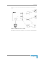
Appendix B – CMAP to RPCU Connections: This appendix describes
how to physically connect the PC that runs the CMAP8000 & RMON
to the MGW RPCU, either directly (locally), or remotely via a Dial-up
modem.
Appendix C – Interconnecting Cables: Provides a list of various
cables needed to perform all the connections and installations.
Appendix D – Time Diversity: This appendix describes the Time
Diversity feature, which enables the MGW system to allocate two
time slots on the radio link, in each frequency hop, to improve the
quality of the telephone connection.
Appendix E – Performance and Traffic Monitoring: Provides
information on sesion and global parameters.
Appendix F – Automatic Software Download: This chapter explains
the Automatic Software DownLoad (ASDL) utility which replaces the
RMON by upgrading and improving operation.
Appendix G – Convert Utility Ver. 1.05: The convert utility described
here reassigns ports of V5.2 single mode E1, initially used in any
MGW system, to new logical ports of V5.2 Multi E1 links.
Appendix H – Windows Load Target: This appendix describes the
flash loading procedure for FAU card software using the Windows
Load Target (WLT) utility program.
CMAP 8000 Installation & Maintenance
ii
About this Guide
Multigain Wireless Technical
Publications
The following list provides details on all the documents relating to
MultiGain Wireless Technical Publications.
MultiGain Wireless System Manual (P/N 8638-71910-00) contains
descriptive information on MultiGain Wireless. The manual includes
the following parts:
Part 1: MultiGain Wireless System Overview – concise
description of system capabilities and components, integration
with CO equipment, general configuration options, optional
equipment and general description of management and
provisioning options. Also, system functionality and technical
descriptions.
Part 2: MultiGain Wireless Central Office/Control and
Interface System Installation and Operation Manual – general
description of the RPCU, GSS, AIU-120 and DIU units, physical
and functional descriptions, site requirements, data related to
installation planning, installation procedures for each item of
equipment, cable connections, first-time operation, configuration
and provisioning procedures, commissioning, troubleshooting
and field maintenance.
Part 3: MultiGain Wireless Radio Port System Installation
and Operation Manual – general description of the RPU and
RPC units and associated antennae, physical and functional
descriptions, site requirements and installation planning,
installation procedures for each item of equipment, cable
connections, first-time operation, configuration and provisioning
procedures, commissioning, troubleshooting and field
maintenance.
Part4: MultiGain Wireless Subscriber System Installation
and Operation Manual – general description of the FAU, PCU
and PDC/4 units, physical and functional descriptions, site
requirements and installation planning, installation procedures
for each item of equipment, cable connections, first-time
operation, configuration and provisioning procedures,
commissioning, troubleshooting and field maintenance.
Revision 1.0
iii
About this Guide
CraftMap - CMAP 8000 Installation and Operation Manual (this
manual) (P/N 8638-71970-00) provides the information required for
installing and operating the CMAP 8000 management tool.
CraftMap - CMAP 8010 Installation and Operation Manual
(P/N 8638-71971-00) provides the information required for
installing and operating the CMAP 8100 management tool.
CraftMap - CMAP 8020 Installation and Operation Manual
(P/N 8638-71972-00) provides the information required for
installing and operating the CMAP 8020 management tool.
SuperOfficeMap - SMAP 8100 Installation and Operation Manual
(P/N 8638-71990-00) provides the information required for
installing and operating the SMAP 8100 management tool.
AIU-120 Concentrator Option Installation and Operation Manual
(P/N 8657-71436-00) provides the information required for AIU-120
installation, operation and maintenance.
DIU Installation and Operation Manual (P/N 8674-71135-00)
provides the information required for DIU installation, operation and
maintenance.
DIU-T1 Installation and Operation Manual (P/N 8657-71960-00)
provides the information required for DIU-T1 installation, operation
and maintenance.
MCX Installation and Operation Manual (P/N 8619-71940-00)
provides the information required the installation, operation and
maintenance of the MGW Coverage eXtender (MCX) system
equipment.
HFIT-2000 Operation Manual (P/N 8626-71921-00) provides
instructions for the operation of the Handheld FAU Installation
Terminal (HFIT-2000).
HFIT Super User Manual (P/N 8626-71471-00) provides super-user
operating instructions for the Handheld FAU Installation Terminal
(HFIT-2000).
HFIT-100 User Manual (P/N 8626-71920-00) provides instructions
for the operation of the Handheld FAU Installation Terminal (HFIT100).
GPS Clock Technical Manual (P/N 8821B-7) provides the
information required for installing and operating the TRAK GPS
receiver.
Symmetricom GPS Receiver (P/N 194-335) provides instructions
for installing and operating the Symmetricom GPS receiver.
CMAP 8000 Installation & Maintenance
iv
About this Guide
Trademarks
MultiGain Wireless is a registered trademark of Alphacell.
Microsoft and MS-DOS are registered trademarks, and Windows is a
trademark of Microsoft Corporation.
IBM-PC is a registered trademark of International Business Machines
Corporation.
Revision 1.0
v
Contents
Chapter 1 - Overview ................................................................................1-1
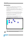
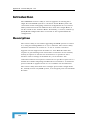
Introduction ........................................................................................... 1-2
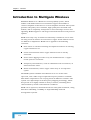
Introduction to Multigain Wireless .......................................................... 1-4
Chapter 2 - Installation .............................................................................2-1
Minimum Hardware Requirements .......................................................... 2-2
Software Installation............................................................................... 2-3
CMAP 8000 Installation................................................................................ 2-3
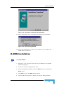
R-MON Installation ...................................................................................... 2-9
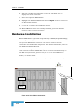
Hardware Installation................................................................................. 2-10
Chapter 3 - Operation ...............................................................................3-1
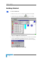
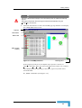
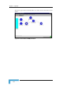
Getting Started....................................................................................... 3-2
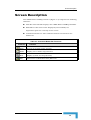
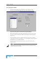
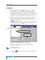
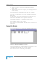
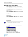
Screen Description ................................................................................. 3-5
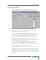
Screen Management................................................................................ 3-8
Chapter 4 - System Workflow ..................................................................4-1
General Description ................................................................................ 4-2
Applicable Software Packages....................................................................... 4-2
Principal Stages ........................................................................................... 4-2
Detailed Description ............................................................................... 4-4
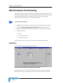
End of Mechanical Installation ..................................................................... 4-4
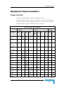
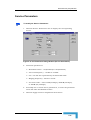
Equipment Synchronization ......................................................................... 4-5
Power Turn On .......................................................................................... 4-5
Check for Equipment Synchronization....................................................... 4-6
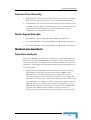
Miscellaneous............................................................................................ 4-7
CMAP Operation........................................................................................... 4-7
A New RPCU.............................................................................................. 4-7
Contents
RPCU Relocation........................................................................................4-7
Equipment Definitions ..................................................................................4-8
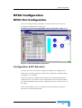
RPCU Configuration ................................................................................ 4-9
RPCU Slot Configuration...............................................................................4-9
Configuration & NIT Selection ....................................................................4-9
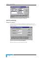
V5.2 Provisioning .....................................................................................4-10
Single E1 Interface ................................................................................4-10
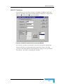
Multi E1 Interface .................................................................................4-11
RPCU Card Changes ...................................................................................4-12
Card Definition ........................................................................................4-12
DNI Card Definition...............................................................................4-12
RPI Card Definition ...............................................................................4-13
Interface Cards ........................................................................................4-14
End Of Card Definition ............................................................................4-15
MPM Redundant Definition ......................................................................4-16
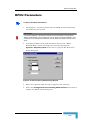
RPCU Parameters .......................................................................................4-17
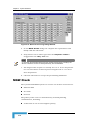
MGW Clock.................................................................................................4-18
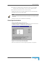
Clock Synchronization .............................................................................4-19
Time and Date .........................................................................................4-20
RPU/RPC Provisioning .......................................................................... 4-21
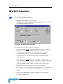
RPU/RPC Definition ...................................................................................4-22
MDSL Definition .........................................................................................4-23
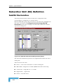
Subscriber Unit (SU) Definition.............................................................. 4-24
Sub/SU Declaration ...................................................................................4-24
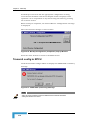
Create ......................................................................................................4-25
RPU-ISDN Assignment .............................................................................4-26
SU-CO Connection...................................................................................4-26
Connection by SU# ...............................................................................4-27
Connection by CO Port..........................................................................4-28
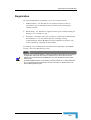
Registration .............................................................................................4-29
Registration by SU# ..............................................................................4-30
Registration by Registration ..................................................................4-32
Status......................................................................................................4-33
SU Deletion ................................................................................................4-33
SU Parameter Provisioning..........................................................................4-34
Selection ..................................................................................................4-34
Service Parameters ..................................................................................4-35
Radio Parameters.....................................................................................4-36
Modify......................................................................................................4-37
GSS Operation (Option) ..............................................................................4-37
CMAP 8000 Installation & Maintenance
ii
Contents
Chapter 5 - Main Map................................................................................5-1
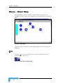
Menu – Main Map.................................................................................... 5-2
File............................................................................................................... 5-2
Edit.............................................................................................................. 5-3
Configuration → Provisioning ....................................................................... 5-4
MDSL Details ............................................................................................ 5-5
RPCU Card And Interface Setup ................................................................ 5-7
V5.2 Single E1 Interface ......................................................................... 5-9
V5.2M E1 Interface............................................................................... 5-10
RPCU Details........................................................................................... 5-11
Time and date ......................................................................................... 5-14
RPU/RPC details ..................................................................................... 5-15
Clock source............................................................................................ 5-18
Sub/SU Parameters ................................................................................ 5-20
Select Mode .......................................................................................... 5-20
Service Parameters ............................................................................... 5-21
Radio Parameters ................................................................................. 5-23
SU Freq Download Edit ........................................................................... 5-25
SU Participants Mode ........................................................................... 5-26
Frequency Series Mode ......................................................................... 5-27
RPU/RPC Phase Download Edit .............................................................. 5-28
RPU/RPC Freq & Phase Download .......................................................... 5-29
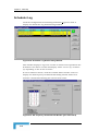
ScHeduler ............................................................................................... 5-30
Scheduler Log.......................................................................................... 5-34
Sub\SU Declaration ................................................................................ 5-35
Select Mode .......................................................................................... 5-36
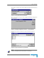
Create................................................................................................ 5-37
Delete ................................................................................................ 5-38
Connection Mode.................................................................................. 5-38
cOnnect SU ....................................................................................... 5-38
ReConnect SU.................................................................................... 5-39
DisConnect SU .................................................................................. 5-39
Add Port ............................................................................................ 5-40
cOnnect SU ....................................................................................... 5-41
ReConnect CO Port ............................................................................ 5-41
DisConnect CO Port........................................................................... 5-41
RPU/RPC-ISDN Mode ........................................................................... 5-42
Registration Mode .............................................................................. 5-44
Status Mode ...................................................................................... 5-46
Configuration → Status & Control .............................................................. 5-47
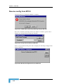
Receive config from RPCU........................................................................ 5-48
Transmit config to RPCU ......................................................................... 5-50
Import RPCU DB ..................................................................................... 5-54
Revision 1.0
iii
Contents
Export Import Frequency & Phase............................................................5-55
Maintenance ...............................................................................................5-56
Clock selection.........................................................................................5-57
SU Status ................................................................................................5-58
Initialize DB .............................................................................................5-59
List all maintenance calls.........................................................................5-60
Terminate all maintenance calls...............................................................5-61
Subscriber Line Test (SLT) .......................................................................5-61
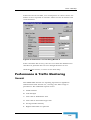
Performance & Traffic Monitoring ...............................................................5-63
General....................................................................................................5-63
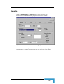
Reports ....................................................................................................5-65
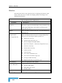
Selection ...............................................................................................5-66
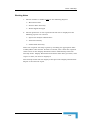
Working Notes....................................................................................5-67
Table.....................................................................................................5-68
Graph ...................................................................................................5-69
Graph Option ........................................................................................5-71
Management ............................................................................................5-72
Get RPCU History..................................................................................5-72
Clear RPCU History...............................................................................5-72
Housekeeping .......................................................................................5-73
Security ......................................................................................................5-75
Options.......................................................................................................5-75
Help............................................................................................................5-75
Chapter 6 - RPCU Shelf ........................................................................... 6-1
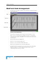
Shelf and Card Arrangement ................................................................... 6-2
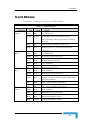
Card Status............................................................................................. 6-3
Shelf Menu.............................................................................................. 6-5
MPM Card ....................................................................................................6-5
File ............................................................................................................6-5
Edit ...........................................................................................................6-5
Configuration.............................................................................................6-6
Maintenance ..............................................................................................6-7
Help...........................................................................................................6-8
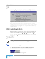
DNI Card (Empty Slot) ..................................................................................6-8
Configuration.............................................................................................6-8
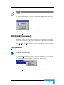
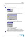
DNI Card (Installed) ......................................................................................6-9
Configuration.............................................................................................6-9
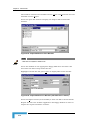
Maintenance ............................................................................................6-11
RPI Card (Empty Slot) .................................................................................6-12
RPI Card (Installed).....................................................................................6-13
NMI Card ....................................................................................................6-13
CMAP 8000 Installation & Maintenance
iv
Contents
Maintenance............................................................................................ 6-13
Chapter 7 - E1 Map ...................................................................................7-1
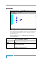
General................................................................................................... 7-2
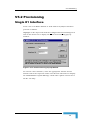
V5.2 Provisioning ................................................................................... 7-3
Single E1 Interface ....................................................................................... 7-3
Multi E1 Interface ........................................................................................ 7-4
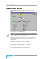
E1 Alarm Status...................................................................................... 7-6
Upgrading an Existing V5.2 Single E1-based MGW System ....................... 7-7
Chapter 8 - RPU/RPC Map........................................................................8-1
General................................................................................................... 8-2
MDSL Alarm Status................................................................................. 8-4
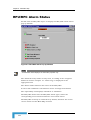
RPU/RPC Alarm Status ........................................................................... 8-6
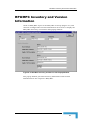
RPU/RPC Inventory and Version Information.......................................... 8-7
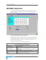
RPU/RPC Statistics ................................................................................ 8-8
Chapter 9 - SU Map...................................................................................9-1
General................................................................................................... 9-2
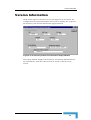
Version Information................................................................................ 9-5
Sub/SU Parameter Provisioning .............................................................. 9-6
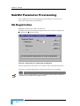
SU Registration ............................................................................................ 9-6
Maintenance ........................................................................................... 9-7
List all maintenance calls ............................................................................. 9-7
Terminate all maintenance calls ................................................................... 9-7
Set maintenance call .................................................................................... 9-7
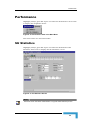
Performance ........................................................................................... 9-9
SU Statistics ................................................................................................ 9-9
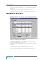
RPU/RPC SU Statistics .............................................................................. 9-10
SU Status.............................................................................................. 9-11
Revision 1.0
v
Contents
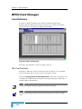
Chapter 10 - Alarm Log.......................................................................... 10-1
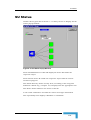
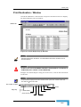
General ................................................................................................. 10-2
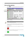
Screen Description................................................................................ 10-3
Menu → File.......................................................................................... 10-7
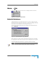
Rebuild Database .......................................................................................10-7
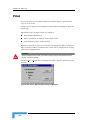
Print ...........................................................................................................10-8
Print Destination - Window ......................................................................10-9
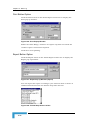
Print Button Option ............................................................................10-10
Export Button Option..........................................................................10-10
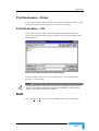
Print Destination - Printer......................................................................10-13
Print Destination – File ..........................................................................10-13
Exit...........................................................................................................10-13
Menu → View ...................................................................................... 10-14
Current/History........................................................................................10-14
Show Details.............................................................................................10-15
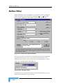
Define Filter..............................................................................................10-16
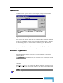
Queries.....................................................................................................10-19
Enable Updates ........................................................................................10-19
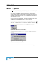
Menu → Attend ................................................................................... 10-20
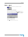
Menu → Clear ..................................................................................... 10-21
Menu → Help ...................................................................................... 10-22
Chapter 11 - Security ............................................................................. 11-1
Security Menu ...................................................................................... 11-2
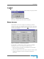
Login ..........................................................................................................11-2
LogOut .......................................................................................................11-3
Menu Access...............................................................................................11-3
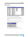
Security Alarm............................................................................................11-4
Access Log ..................................................................................................11-5
Chapter 12 - Options.............................................................................. 12-1
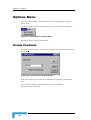
Options Menu ....................................................................................... 12-2
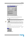
Comm Features ..........................................................................................12-2
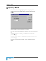
Frequency Band .........................................................................................12-4
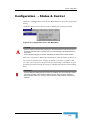
Modem commands......................................................................................12-5
Modem operation ........................................................................................12-6
CMAP 8000 Installation & Maintenance
vi
Contents
Chapter 13 - Help ....................................................................................13-1
General................................................................................................. 13-2
Appendix A - Remote Monitoring (RMON)............................................. A-1
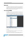
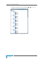
General................................................................................................... A-2
Accessing RMON .......................................................................................... A-2
TYPICAL View ......................................................................................... A-5
Main Menu → File ........................................................................................ A-5
Main Menu → View ...................................................................................... A-5
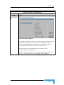
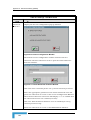
Main Menu → Settings ................................................................................. A-6
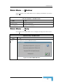
Main Menu → Window ................................................................................. A-9
Main Menu → Help....................................................................................... A-9
Monitoring & Control............................................................................ A-10
RPU/RPC Selection .................................................................................... A-10
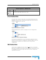
Port Selection ............................................................................................. A-17
SU Selection............................................................................................... A-17
RPCU Selection .......................................................................................... A-19
Exit From RMON ........................................................................................ A-19
Appendix B - CMAP to RPCU Connections ........................................... B-1
General................................................................................................... B-2
Connections Instructions........................................................................ B-3
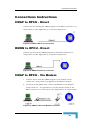
CMAP to RPCU - Direct ................................................................................ B-3
RMON to RPCU - Direct................................................................................ B-3
CMAP to RPCU - Via Modem ........................................................................ B-3
RMON to RPCU - Via Modem........................................................................ B-4
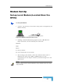
Modem Set-Up ........................................................................................ B-5
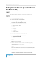
Set-up Local Modem (Located Near the RPCU).............................................. B-5
Set-up Remote Modem (Located Next to the Remote PC) ............................... B-6
CMAP ........................................................................................................ B-6
RMON ....................................................................................................... B-6
Appendix C - Interconnecting Cables .................................................... C-1
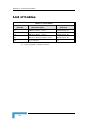
List of Cables .......................................................................................... C-2
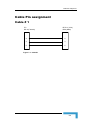
Cable Pin assignment.............................................................................. C-3
Cable # 1...................................................................................................... C-3
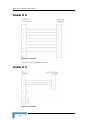
Cable # 2...................................................................................................... C-4
Revision 1.0
vii
Contents
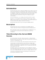
Cable # 3 ..................................................................................................... C-4
Appendix D - Time Diversity ...................................................................D-1
Introduction ...........................................................................................D-2
Description .................................................................................................. D-2
Time Diversity in the Current MGW Version ................................................ D-2
Feature Activation ..................................................................................D-3
RPU/RPC Related Actions............................................................................ D-3
FAU Related Actions .................................................................................... D-3
Appendix E - Performance & Traffic Monitoring ................................... E-1
Performance Monitoring.......................................................................... E-2
Session Parameters ..................................................................................... E-2
WER ......................................................................................................... E-2
Session Time Diversity .............................................................................. E-3
Radio Signal Strength ............................................................................... E-3
Global parameters ....................................................................................... E-3
Spectrum Analysis .................................................................................... E-3
Antennae Diversity.................................................................................... E-4
Global Time Diversity................................................................................ E-4
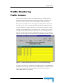
Traffic Monitoring................................................................................... E-5
Traffic Volume ............................................................................................. E-5
Call Attempts............................................................................................... E-6
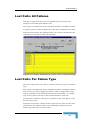
Lost Calls: All Failures ................................................................................. E-7
Lost Calls: Per Failure Type ......................................................................... E-7
Average Traffic Intensity .............................................................................. E-9
Highest Time Slot Occupancies .................................................................... E-9
Appendix F - Automatic Software Download......................................... F-1
Introduction ........................................................................................... F-2
ADSL Operation ...................................................................................... F-4
Getting Started .............................................................................................F-4
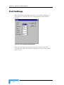
Port Settings .................................................................................................F-6
Connection/Disconnection ...........................................................................F-7
Device Selection............................................................................................F-8
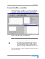
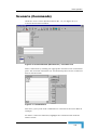
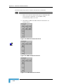
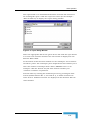
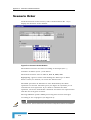
Scenario (Commands) ...................................................................................F-9
Scenario Order ...........................................................................................F-12
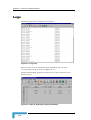
Logs...................................................................................................... F-14
CMAP 8000 Installation & Maintenance
viii
Contents
Selected Main Menu Items .................................................................... F-16
Appendix G - Convert Utility Ver. 1.05 ................................................... G-1
Introduction ........................................................................................... G-2
Description ..................................................................................................G-2
Implementation ...................................................................................... G-3
Initial Steps..................................................................................................G-3
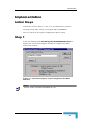
Step 1 ..........................................................................................................G-3
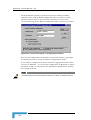
Step 2 ..........................................................................................................G-5
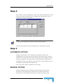
Step 3 ..........................................................................................................G-5
AUTOMATIC OPTION.................................................................................G-5
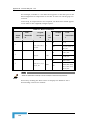
MANUAL OPTION ......................................................................................G-5
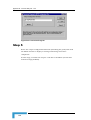
Step 4 ..........................................................................................................G-7
Step 5 ..........................................................................................................G-8
Appendix H - Windows Load Target ...................................................... H-1
FAU Setup .............................................................................................. H-2
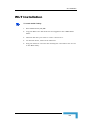
WLT Installation ..................................................................................... H-3
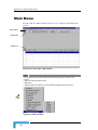
Main Menu.............................................................................................. H-4
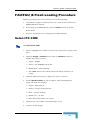
FAU/FAU_B Flash Loading Procedure ...................................................... H-7
Select PC COM .............................................................................................H-7
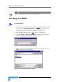
Loading the BOOT........................................................................................H-8
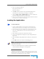
Loading the Application................................................................................H-9
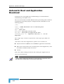
Automatic Boot and Application Download.................................................H-10
Revision 1.0
ix
Figures
Figure 1-1: CraftMap Interface ........................................................................... 1-2
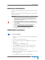
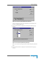
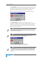
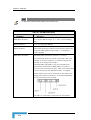
Figure 2-1: Attention Pop-up Window ................................................................ 2-4
Figure 2-2: Installation Wizard Screen No. 1 ...................................................... 2-4
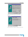
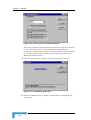
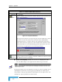
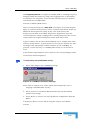
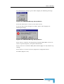
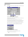
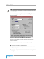
Figure 2-3: Select Destination Directory Pop-up Window.................................... 2-5
Figure 2-4: Ready to Install Pop-up Window....................................................... 2-5
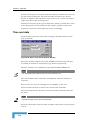
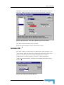
Figure 2-5: Installing Pop-up Window ................................................................ 2-6
Figure 2-6: Icon on Desktop Pop-up Window...................................................... 2-6
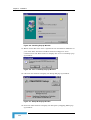
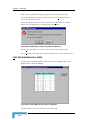
Figure 2-7: Setup INI Pop-up Window ................................................................ 2-6
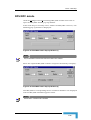
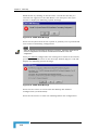
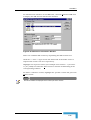
Figure 2-8: Frequency Hopping Mode Pop-up Window ....................................... 2-7
Figure 2-9: Set Frequency Band Pop-up Window ............................................... 2-7
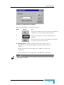
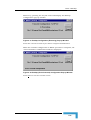
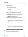
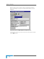
Figure 2-10: Communication Port Pop-up Window ............................................. 2-8
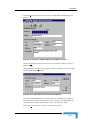
Figure 2-11: The End Pop-up Window ................................................................ 2-8
Figure 2-12: Installation Completed Pop-up Window .......................................... 2-9
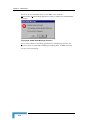
Figure 2-13: Install Pop-up Window ................................................................... 2-9
Figure 2-14: PC to RPCU Connection ............................................................... 2-10
Figure 3-1: CraftMap Logo - Opening Screen ...................................................... 3-2
Figure 3-2: CraftMap Cautionary Message ......................................................... 3-2
Figure 3-3: CraftMap Interface ........................................................................... 3-3
Figure 3-4: Annotated CraftMap Interface .......................................................... 3-4
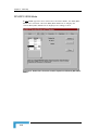
Figure 3-5: Properties Window ........................................................................... 3-6
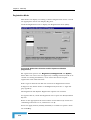
Figure 3-6: Comm Features (example) ................................................................ 3-7
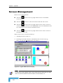
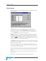
Figure 3-7: Typical Multi Screen Display ............................................................ 3-8
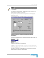
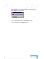
Figure 3-8: CMAP-8000 Message........................................................................ 3-9
Figures
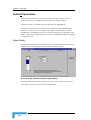
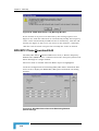
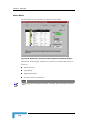
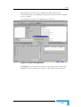
Figure 3-9: CraftMap Interface - E1 Group Sub-map ........................................3-11
Figure 4-1: RPCU Predefined Configuration ........................................................4-9
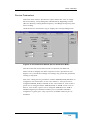
Figure 4-2: RPCU Slot Configuration Dialog Box ...............................................4-10
Figure 4-3: V5.2 Provisioning Dialog Window....................................................4-10
Figure 4-4: Multi E1 V5.2 Provisioning Pop-up Window ....................................4-11
Figure 4-5: DNI Card Definition ........................................................................4-12
Figure 4-6: RPI Card Definition ........................................................................4-13
Figure 4-7: RPCU Shelf – Card Deletion ............................................................4-14
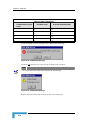
Figure 4-8: CMA 8000 Message ........................................................................4-14
Figure 4-9: RPCU Network Map ........................................................................4-15
Figure 4-10: RPCU Shelf – Enable MPM Redundancy .......................................4-16
Figure 4-11: CMAP 8000 Message Window .......................................................4-16
Figure 4-12: Set Frequency Band Dialog Window .............................................4-17
Figure 4-13: RPCU Provisioning Dialog Window ................................................4-18
Figure 4-14: Clock Priority Table Dialog Box .....................................................4-19
Figure 4-15: Time & Date Dialog Box ................................................................4-20
Figure 4-16: RPU/RPC Definitions....................................................................4-21
Figure 4-17: RPU/RPC Details Dialog Box ........................................................4-22
Figure 4-18: MDSL – Details Dialog Box ...........................................................4-23
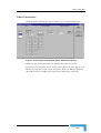
Figure 4-19: Subscriber Allocation and SU Operations (Select) ..............................4-24
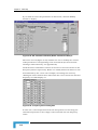
Figure 4-20: Subscriber Allocation and SU Operations (RPU-ISDN) .......................4-26
Figure 4-21: Subscriber Allocation and SU Operations (Connection I) ....................4-27
Figure 4-22: Subscriber Allocation and SU Operations (Connection II) ...................4-28
Figure 4-23: Subscriber Allocation and SU Operations (Registration I) ...................4-30
Figure 4-24: Subscriber Allocation and SU Operations (Registration II) ..................4-32
Figure 4-25: Subscriber Allocation and SU Operations (Status) ........................4-33
Figure 4-26: SU Parameters Dialog Window (Select)..........................................4-34
Figure 4-27: SU Parameters Dialog Window (Service Parameters) .....................4-35
Figure 4-28: SU Parameters Dialog Window (Radio Parameters) .......................4-36
CMAP 8000 Installation & Maintenance
ii
Figures
Figure 4-29: Modify Button .............................................................................. 4-37
Figure 5-1: Main Map ........................................................................................ 5-2
Figure 5-2: File Item in the Menu Bar ................................................................ 5-2
Figure 5-3: CMAP-8000 Pop-up Window ............................................................ 5-3
Figure 5-4: Edit Item in the Menu Bar ............................................................... 5-3
Figure 5-5: Configuration Item in the Menu Bar................................................. 5-4
Figure 5-6: Provisioning Item ............................................................................. 5-4
Figure 5-7: MDSL Details Pop-up Window (1) ..................................................... 5-5
Figure 5-8: MDSL Details Pop-up Window (2) ..................................................... 5-5
Figure 5-9: CMAP 8000 (Accepted) Message ....................................................... 5-6
Figure 5-10: RPCU Slot Configuration Dialog Window (1) ................................... 5-7
Figure 5-11: RPCU Slot Configuration Dialog Window (2) ................................... 5-7
Figure 5-12: CMAP 8000 (Cautionary) Message .................................................. 5-8
Figure 5-13: RPCU Slot Configuration Dialog Window (3) ................................... 5-8
Figure 5-14: CMAP 8000 (Accepted) Message ..................................................... 5-8
Figure 5-15: RPCU Slot Configuration Dialog Window (4) ................................... 5-9
Figure 5-16: RPCU Slot Configuration Dialog Window (5) ................................. 5-10
Figure 5-17: Multi E1 Status Pop-up Window .................................................. 5-11
Figure 5-18: RPCU - DETAILS Pop-up Window ................................................ 5-11
Figure 5-19: CraftMap Message........................................................................ 5-12
Figure 5-20: CMAP 8000 Message Pop-up Window........................................... 5-12
Figure 5-21: CraftMap Confirmation Message .................................................. 5-13
Figure 5-22: RPCU Time & Date Pop-up Window ............................................. 5-14
Figure 5-23: RPU/RPC Details Pop-up Window (1) ........................................... 5-15
Figure 5-24: RPU/RPC Details Pop-up Window (2) ........................................... 5-15
Figure 5-25: CMAP-8000 Message Pop-up Window .......................................... 5-17
Figure 5-26: CMAP-8000 Message Pop-up Window .......................................... 5-17
Figure 5-27: RPCU - Clock Priority Table Pop-up Window ................................ 5-18
Figure 5-28: Priority Box .................................................................................. 5-19
Revision 1.0
iii
Figures
Figure 5-29: CMAP-8000 (Warning) Message ....................................................5-19
Figure 5-30: SU Parameters Window (Select Mode) ...........................................5-20
Figure 5-31: SU Parameters Window (Service Parameters Mode) .......................5-21
Figure 5-32: CMAP8000 Message .....................................................................5-22
Figure 5-33: CMAP8000 Message .....................................................................5-22
Figure 5-34: SU Parameters Window (Radio Parameters Mode) I .......................5-23
Figure 5-35: SU Parameters Window (Radio Parameters Mode) II ......................5-24
Figure 5-36: Frequency Series Dialog Box.........................................................5-24
Figure 5-37: CMAP8000 Message .....................................................................5-25
Figure 5-38: SU Frequency Download Edit (SU Participants) ............................5-26
Figure 5-39: SU Frequency Download Edit (Frequency Series) ..........................5-27
Figure 5-40: CMAP 8000 (False Lock) Message Window ....................................5-28
Figure 5-41: RPU/RPC Phase Download Edit Dialog Window (Phase Settings) ..5-28
Figure 5-42: RPU/RPC Phase Download Edit Dialog Window (Frequency Series) ..529
Figure 5-43: CMAP-8000 Message (RPU/RPC Freq & Phase Download) ............5-29
Figure 5-44: Scheduler Dialog Window – General View .....................................5-30
Figure 5-45: Action Item List Box .....................................................................5-31
Figure 5-46: SU Frequency Download Edit (SU Participants) ............................5-31
Figure 5-47: Date Field .....................................................................................5-32
Figure 5-48: Saved Action Item .........................................................................5-33
Figure 5-49: CMAP-8000 (Confirm Deletion) Message Window ..........................5-33
Figure 5-50: Scheduler Log Details Dialog Window ...........................................5-34
Figure 5-51: SU Frequency Download Edit Window (plus Fault Field) ...............5-34
Figure 5-52: Frequency Download Status Window ............................................5-35
Figure 5-53: Subscriber Allocation and SU Operations Window (Select) ............5-36
Figure 5-54: Subscriber Allocation and SU Operations Window (Connections) ..5-38
Figure 5-55: Subscriber Allocation and SU Operations Window (Connection)....5-40
Figure 5-56: SU# and SU Port Combo Boxes ....................................................5-41
CMAP 8000 Installation & Maintenance
iv
Figures
Figure 5-57: Subscriber Allocation and SU Operations Window (RPU/RPC-ISDN) I
.................................................................................................................. 5-42
Figure 5-58: Subscriber Allocation and SU Operations Window (RPU/RPC-ISDN) II
.................................................................................................................. 5-43
Figure 5-59: Subscriber Allocation and SU Operations Window (Registration) .. 5-44
Figure 5-60: Subscriber Allocation and SU Operations Window (Registration) .. 5-45
Figure 5-61: Registration Filter Combo Box...................................................... 5-45
Figure 5-62: Subscriber Allocation and SU Operations Window (Status) .......... 5-46
Figure 5-63: Configuration Item in the Main Menu .......................................... 5-47
Figure 5-64: CMAP-8000 (Cautionary) Message Pop-up Window ...................... 5-48
Figure 5-65: Verify Password Pop-up Window .................................................. 5-48
Figure 5-66: Backup Configuration Pop-up Window ......................................... 5-48
Figure 5-67: Open Receive-File Pop-up Window ............................................... 5-49
Figure 5-68: Open Receive-File (Error Message) Pop-up Window ...................... 5-49
Figure 5-69: Backup Configuration (RPCU Executing) Pop-up Window ............ 5-49
Figure 5-70: Backup Configuration (Completion) Pop-up Window .................... 5-50
Figure 5-71: CMAP-8000 (Cautionary) Message................................................ 5-50
Figure 5-72: Verify Password Pop-up Window .................................................. 5-51
Figure 5-73: Backup Configuration (Transmit. . .) Pop-up Window ................... 5-51
Figure 5-74: Open Transmit-File Pop-up Window ............................................. 5-51
Figure 5-75: CMAP 8000 Message .................................................................... 5-52
Figure 5-76: CMAP 8000 Message .................................................................... 5-52
Figure 5-77: Backup Configuration (Executing) Pop-up Window ...................... 5-53
Figure 5-78: Backup (End of transmit) Configuration Pop-up Window.............. 5-53
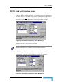
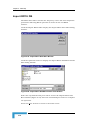
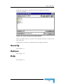
Figure 5-79: Import RPCU Data Base Window.................................................. 5-54
Figure 5-80: Import RPCU DataBase Details Files Window ............................... 5-54
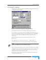
Figure 5-81: Import / Export System Frequency & Phase Dialog Window......... 5-55
Figure 5-82: Enter/Select File Dialog Window .................................................. 5-55
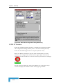
Figure 5-83: Import / Export System Frequency & Phase Dialog Window – “Action
Was Successful” ........................................................................................ 5-56
Revision 1.0
v
Figures
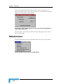
Figure 5-84: Maintenance Item in the Main Menu ............................................5-56
Figure 5-85: RPCU - Clock Select Pop-up Window ............................................5-57
Figure 5-86: CMAP-8000 (Cautionary) Message ................................................5-57
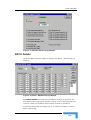
Figure 5-87: Subscriber Units Status Window ..................................................5-58
Figure 5-88: Subscriber Units Status Window (plus alarm status) ....................5-59
Figure 5-89: Initialize Data Base Window .........................................................5-59
Figure 5-90: CMAP-8000 (Cautionary) Message Window ...................................5-60
Figure 5-91: Active Maintenance Call List Window............................................5-60
Figure 5-92: Subscriber Line Test Dialog Window I ...........................................5-61
Figure 5-93: Subscriber Line Test Dialog Window II ..........................................5-63
Figure 5-94: Performance Item on the Main Menu ............................................5-64
Figure 5-95: CMAP-8000 (Cautionary) Message ................................................5-64
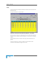
Figure 5-96: Performance/Traffic Monitoring Reports Window ..........................5-65
Figure 5-97: Performance/Traffic Monitoring Reports – Table Mode ..................5-68
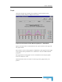
Figure 5-98: Performance/Traffic Monitoring Reports – Graph Mode ................5-69
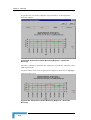
Figure 5-99: Performance/Traffic Monitoring Reports I – (Antennae Diversity) ..5-70
Figure 5-100: Performance/Traffic Monitoring Reports II – (Antennae Diversity)5-70
Figure 5-101: Performance/Traffic Monitoring Reports III –
(Antennae Diversity) ...................................................................................5-71
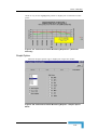
Figure 5-102: Performance/Traffic Monitoring Reports – Graphic Option Mode 5-71
Figure 5-103: CMAP-8000 (Confirmatory) Message ...........................................5-72
Figure 5-104: Delete Performance Monitoring Data Window .............................5-73
Figure 5-105: CMAP-8000 (Confirmatory) Message ...........................................5-73
Figure 5-106: Export Performance Monitoring Data Window.............................5-74
Figure 5-107: Enter The Report File Name Window...........................................5-75
Figure 6-1: RPCU Shelf Display ..........................................................................6-2
Figure 6-2: DNI-9 Card Status ............................................................................6-4
Figure 6-3: File Item in the Main Menu...............................................................6-5
Figure 6-4: CMAP-8000 Pop-up Window .............................................................6-5
Figure 6-5: Edit Item in the Main Menu ..............................................................6-5
CMAP 8000 Installation & Maintenance
vi
Figures
Figure 6-6: Configuration Item in the Main Menu .............................................. 6-6
Figure 6-7: CMAP-8000 Message........................................................................ 6-6
Figure 6-8: Maintenance Item in the Main Menu ................................................ 6-7
Figure 6-9: MPM Redundant Dialog Window ...................................................... 6-7
Figure 6-10: MPM Status Window ...................................................................... 6-7
Figure 6-11: About CraftMap Pop-up Window .................................................... 6-8
Figure 6-12: Install Item Under Configuration .................................................... 6-8
Figure 6-13: CMAP 8000 (Accepted) Message ..................................................... 6-9
Figure 6-14: Provisioning Item ........................................................................... 6-9
Figure 6-15: CMAP-8000 Message.................................................................... 6-10
Figure 6-16: CMAP-8000 (Accepted) Message ................................................... 6-10
Figure 6-17: Maintenace Item in the Main Menu .............................................. 6-11
Figure 6-18: CMAP 8000 (Cautionary) Message ................................................ 6-11
Figure 6-19: CMAP 8000 (Accepted) Message ................................................... 6-11
Figure 6-20: Current SW Download Status (In Progress) Window ..................... 6-12
Figure 6-21: Maintenance Item in the Main Menu ............................................ 6-13
Figure 6-22: Import SW Versions Window ........................................................ 6-13
Figure 6-23: Import SW Version Files Window ................................................. 6-14
Figure 6-24: Import SW Versions Window (with SW version details) ................. 6-14
Figure 6-25: SW Version Information Window .................................................. 6-15
Figure 6-26: Section of CMAP (SW Download Status) Screen ............................ 6-16
Figure 6-27: Section of CMAP (SW Download Status) Screen ............................ 6-17
Figure 6-28: Current SW version Information Window ..................................... 6-17
Figure 6-29: CMAP 8000 Message (Caution) ..................................................... 6-18
Figure 7-1: CMAP-8000 E1 Group Sub Map ....................................................... 7-2
Figure 7-2: E1 V5.2 Provisioning Pop-up Window .............................................. 7-3
Figure 7-3: Multi E1 V5.2 Provisioning Pop-up Window ..................................... 7-4
Figure 7-4: E1 Status Pop-up Window ............................................................... 7-6
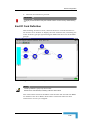
Figure 8-1: CMAP-8000 - RPU/RPC Sub Map .................................................... 8-2
Revision 1.0
vii
Figures
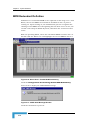
Figure 8-2: MDSL Status Pop-up Window ...........................................................8-4
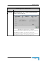
Figure 8-3: RPU/RPC Status Pop-up Window .....................................................8-6
Figure 8-4: RPU/RPC Inventory and Version Info Popup Window .......................8-7
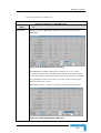
Figure 8-5: RPU/RPC Statistics (View by DSLs) ..................................................8-8
Figure 8-6: RPU/RPC Statistics (View by Air Slots) .............................................8-9
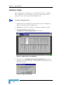
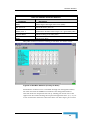
Figure 9-1: SU Group Selection Window .............................................................9-2
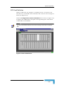
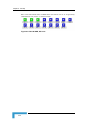
Figure 9-2: Subscriber Unit Array Screen ...........................................................9-2
Figure 9-3: View Item in the Main Menu .............................................................9-3
Figure 9-4: SU 321 – 384 Array ..........................................................................9-3
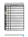
Figure 9-5: Data & ISDN, SU Icons .....................................................................9-4
Figure 9-6: SU Inventory and Version Information Popup Window ......................9-5
Figure 9-7: Registration For Subscriber Unit Window .........................................9-6
Figure 9-8: Maintenance Item in the Main Menu ................................................9-7
Figure 9-9: SU Maintenance Call Activity Popup Window....................................9-7
Figure 9-10: Performance Item in the Main Menu ...............................................9-9
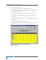
Figure 9-11: SU Statistics Screen .......................................................................9-9
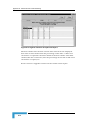
Figure 9-12: RPU/RPC SU Statistics Screen .....................................................9-10
Figure 9-13: SU Status Popup Window .............................................................9-11
Figure 10-1: Alarm Log .....................................................................................10-3
Figure 10-2: File Item in the Main Menu...........................................................10-7
Figure 10-3: Rebuild Database Pop-up Window ................................................10-7
Figure 10-4: Print - Report Options Pop-up Window .........................................10-8
Figure 10-5: Alarm Report Pop-up Window .......................................................10-9
Figure 10-6: Print Pop-up Window ..................................................................10-10
Figure 10-7: Export Pop-up Window (Export) ..................................................10-10
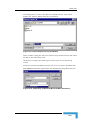
Figure 10-8: Format Drop-Down List Box .......................................................10-10
Figure 10-9: Choose Export File Pop-up Window ............................................10-11
Figure 10-10: Export Pop-up Window (Microsoft Mail Destination) .................10-11
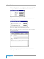
Figure 10-11: Character-Separated Values Window ........................................10-12
CMAP 8000 Installation & Maintenance
viii
Figures
Figure 10-12: Number and Date Format Dialog Window ................................ 10-12
Figure 10-13: Send Mail Window ................................................................... 10-12
Figure 10-14: Enter The Report File Name Window ........................................ 10-13
Figure 10-15: View Item in the Main Menu .................................................... 10-14
Figure 10-16: CMAP 8000 (No More Information) Message ............................. 10-15
Figure 10-17: Select Filter Options Window ................................................... 10-16
Figure 10-18: “Sort By” Frame ....................................................................... 10-16
Figure 10-19: Filter Selection Frame .............................................................. 10-17
Figure 10-20: Enter Filter Name Pop-up Window ........................................... 10-17
Figure 10-21: Alarm Log (Subject to Filter Conditions) ................................... 10-18
Figure 10-22: Queries Pop-up Window ........................................................... 10-19
Figure 10-23: Attend Item in the Main Menu ................................................. 10-20
Figure 10-24: CMAP-8000 Message................................................................ 10-20
Figure 10-25: Clear Item in the Main Menu.................................................... 10-21
Figure 10-26: CMAP-8000 Message................................................................ 10-21
Figure 11-1: Security Item in the Main Menu ................................................... 11-2
Figure 11-2: LOGIN pop-up window ................................................................. 11-2
Figure 11-3: CMAP-8000 Message Pop-up Window .......................................... 11-3
Figure 11-4: SECURITY - ACCESS Pop-up Window .......................................... 11-3
Figure 11-5: SECURITY ALARM Pop-up Window .............................................. 11-4
Figure 11-6: SECURITY ACCESS LOG Pop-up Window .................................... 11-5
Figure 11-7: CMAP-8000 Message Pop-up Window .......................................... 11-5
Figure 12-1: Options Item in the Main Menu.................................................... 12-2
Figure 12-2: Comm Features Pop-up Window I ................................................ 12-2
Figure 12-3: Comm Features Pop-up Window II ............................................... 12-3
Figure 12-4: Options Menu .............................................................................. 12-3
Figure 12-5: Set Frequency Band Pop-up Window............................................ 12-4
Figure 12-6: Modem Information Window ........................................................ 12-5
Figure 12-7: Modem operation Window ............................................................ 12-6
Revision 1.0
ix
Figures
Figure 12-8: Address Book Window ..................................................................12-6
Figure 13-1: About CMAP-8000 Pop-up Window ...............................................13-2
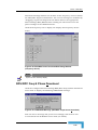
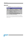
Figure A-1: MGW Remote Monitor - DNI View .....................................................A-2
Figure A-2: MGW Remote Monitor - RPU/RPC View ............................................A-3
Figure A-3: MGW Monitor - Subscriber Unit View ...............................................A-4
Figure A-4: Serial Port Configuration Window .....................................................A-6
Figure A-5: Options Window ...............................................................................A-7
Figure A-6: Access Configuration Window...........................................................A-8
Figure A-7: Unlock Advanced Features Window ..................................................A-8
Figure A-8: About RMON Window .......................................................................A-9
Figure A-9: Operations Sub Menu Items ...........................................................A-10
Figure A-10: RPU/RPC Statistics (slot sort) ......................................................A-11
Figure A-11: RPU/RPC Statistics (DSL sort) .....................................................A-11
Figure A-12: Version Information of RPU/RPC ..................................................A-13
Figure A-13: RLM of RPU/RPC (Load Flash Dialog Window)..............................A-14
Figure A-14: Open Dialog Window ....................................................................A-15
Figure A-15: Terminal Emulation of RPU/RPC..................................................A-16
Figure A-16: Maintenance Call Box...................................................................A-17
Figure A-17: Active Configuration Display ........................................................A-17
Figure A-18: Operations Sub Menu ..................................................................A-18
Figure A-19: RLM of SU (Load Flash Dialog Window) ........................................A-18
Figure A-20: Terminal Emulation of SU ............................................................A-19
Figure A-21: Terminate All the Maint. Calls Box ...............................................A-19
Figure B-1:CMAP to RPCU J15 Connection ....................................................... B-3
Figure B-2: RMON to RPCU J4 Connection ........................................................ B-3
Figure B-3: CMAP to RPCU Via Modem Connection ........................................... B-3
Figure B-4: RMON to RPCU Via Modem Connection .......................................... B-4
Figure B-5: Modem Connection Direct to PC ...................................................... B-5
Figure C-1: Cable #1 ......................................................................................... C-3
CMAP 8000 Installation & Maintenance
x
Figures
Figure C-2: Cable #2 .......................................................................................... C-4
Figure C-3: Cable #3 .......................................................................................... C-4
Figure E-1: Traffic Volume Report: Sector Level, Continuous Display ................. E-5
Figure E-2: Call Attempts: Sector Level, Continuous Display.............................. E-6
Figure E-3: Lost Calls; All Failures (%): Sector Level, Continuous Display .......... E-7
Figure E-4: Lost Calls Per Failure Type: Sector Level, Continuous Display ......... E-8
Figure E-5: Average Traffic Intensity: Sector Level, Continuous Display ............. E-9
Figure E-6: Highest Time Slot Occupancies Report........................................... E-10
Figure F-1: MGW Units involved in ASDL ........................................................... F-3
Figure F-2: ASDL Main Screen ........................................................................... F-4
Figure F-3: Port Settings Dialog Window ............................................................ F-6
Figure F-4: ASDL Main Screen (Logs Window active) .......................................... F-7
Figure F-5: Device Configuration Window (RPU-A device) ................................... F-8
Figure F-6: Scenario Window (RPU-A device) – truncated view............................ F-9
Figure F-7: Command Pane ............................................................................... F-9
Figure F-8: RPU-B Command Functions .......................................................... F-10
Figure F-9: SRM Command Functions ............................................................. F-10
Figure F-10: SIM Command Functions ............................................................ F-10
Figure F-11: Open Dialog Window .................................................................... F-11
Figure F-12: Scenario Order Window ............................................................... F-12
Figure F-13: Log Pane ...................................................................................... F-14
Figure F-14: Device: Downloading Process Window .......................................... F-14
Figure F-15: Report Saving Window ................................................................. F-15
Figure F-16: Save Changes To File Dialog Window ........................................... F-16
Figure F-17: This Will End Your ASDl Session Dialog Window ......................... F-17
Figure G-1: Conversion Program – Input Configuration File Name Selection .......G-3
Figure G-2: Conversion Program – Configuration Selection ................................G-4
Figure G-3: Conversion Program - Automatic Conversion ...................................G-5
Figure G-4: Conversion Program - Multi E1 V5.2 Provisioning............................G-7
Revision 1.0
xi
Figures
Figure G-5: Conversion Program........................................................................ G-8
Figure H-1: FAU Card Setup .............................................................................. H-2
Figure H-2: Load Target – Main Screen .............................................................. H-4
Figure H-3: Shortcut Menu................................................................................ H-4
Figure H-4: Main Screen Incorporating Terminal; Window ................................. H-6
Figure H-5: Password Dialog Popup Window...................................................... H-8
Figure H-6: Open Dialog Window (sample) ......................................................... H-8
CMAP 8000 Installation & Maintenance
xii
Tables
Table 3-1: Command Button Bar Functions....................................................... 3-5
Table 3-2: Examples of Main Map Objects.......................................................... 3-9
Table 3-3: Alarm Status Colors ........................................................................ 3-10
Table 4-1: Stages of MGW System Implementation............................................. 4-3
Table 4-2: LED Indicators Status ....................................................................... 4-5
Table 5-1: Field/Box Definitions ...................................................................... 5-16
Table 5-2: Basic Parameters............................................................................. 5-22
Table 5-3: Display Profile Parameters............................................................... 5-66
Table 6-1: LED Card Types ................................................................................ 6-3
Table 7-1: RPU/RPC Sub Map Menus ................................................................ 7-2
Table 8-1: RPU/RPC Sub Map Menus ................................................................ 8-3
Table 8-2: RPU/RPC Parameter Statistics .......................................................... 8-8
Table 10-1: Alarm Log Details .......................................................................... 10-4
Table 10-2: Severity ......................................................................................... 10-4
Table 10-3: Object ID ....................................................................................... 10-5
Table 10-4: Probable Causes of Alarm Types .................................................... 10-6
Table A-1: File - Sub Menu Items ....................................................................... A-5
Table A-2: View - Sub Menu Items ..................................................................... A-5
Table A-3: Settings - Sub Menu Items ................................................................ A-6
Table A-4: Window – Sub Menu Items ................................................................ A-9
Table A-5: Help – Sub Menu Items ..................................................................... A-9
Table A-6: Operations – Sub Menu Items ......................................................... A-11
Table A-7: Operations Sub Menu ..................................................................... A-18
Tables
Table C-1: List of Cables.................................................................................... C-2
Table F-1: Toolbar Button Options .....................................................................F-4
Table G-1: Basic Parameters.............................................................................. G-6
Table G-2: V5 Variant Data Elements ................................................................ G-7
Table H-1: Button Bar ....................................................................................... H-5
CMAP 8000 Installation & Maintenance
ii
1
Chapter 1 - Overview
In this Chapter
Introduction, page 1-2
Introduction to Multigain Wireless, page 1-4
Chapter 1 - Overview
Introduction
The CMAP 8000 is a CraftMap maintenance and administration
program for navigating the MultiGain Wireless System environment.
CraftMap practice makes the perfect craftsman.
The CMAP 8000, incorporating RMON - MGW Remote MONitor program
(see Appendix A) enables effortless site and customer equipment
installation. The RMON utility handles remote software downloading to
RPU/RPCs/FAUs.
The program offers the user an easy-to-use Man Machine Interface,
featuring intuitive data entering capability for smooth communication
with the management resources of the MultiGain Wireless System..
The CraftMap functions as a single shelf Network Element (NE)
management station for the MGW system.
CraftMap provides for total system control from the C.O. to the
subscriber’s residence. The multi-tasking Windows platform enables
several CraftMap windows to run simultaneously.
Figure 1-1: CraftMap Interface
NOTE
In all figures throughout the manual, RPU should read RPU/RPC
CMAP 8000 Installation & Maintenance
1-2
Introduction
A highly beneficial feature of the CraftMap program is the enabling of
graphic display of the system and its component parts according to a
pre-defined color classification. Thus, the current alarm status is
ascertained by observing the color display of the element, e.g., a faulty
RPU/RPC will display “red.” If, for example, the “RPU/RPC 15.1...”
element (see Figure 1-1) displays “red,” then one of the RPU/RPC’s of
that group is faulty. The specific RPU/RPC is determined by doubleclicking on the group object to display the next, more detailed display
level, showing the layout of the individual RPU/RPC’s with the faulty
RPU/RPC colored red. The subsequent stage is to identify the fault and
obtain the appropriate solution using the interactive CraftMap menu.
Only enabled menu items for a highlighted element (the element in
focus) are visible. A physical view of the element is obtained by doubleclicking on the element. The physical representation includes alarm
displays, etc.
The Windows screen comprises the product logo, menu bar, command
buttons and data entry window: maps, data entry, equipment views
The CMAP 8000 map menu (main) items include:
File, Edit, Configuration, Maintenance, Performance, Security, Option
and Help, where the italicized items are in accordance with TMN
(Telecommunications Management Networks) requirements.
Revision 1.0
1-3
Chapter 1 - Overview
Introduction to Multigain Wireless
MultiGain Wireless is a Wireless Local Loop (WLL) system, which
utilizes radio links instead of conventional copper based links to
connect telephone subscribers to a local telephone network. The system
provides toll quality voice channels, high quality data facsimile and
modem, and is completely transparent to local exchange services and
signaling. MGW supports a full range of network interfaces and protocol
options.
MGW is not only easy to install and extremely economical, but is often
the only practical solution in areas where copper-based infrastructures
are difficult to implement. MGW can be applied to the following
scenarios:
New urban or suburban housing developments without an existing
copper infrastructure.
Urban environments where copper infrastructure is already
saturated.
Areas where digging in order to lay the foundations for a copperbased system is restricted.
Temporary environments, such as exhibitions and conventions, as
well as disaster zones.
Rural environments, where copper cables may be an expensive
option.
The MGW system is flexible and efficient in its use of the radio
spectrum, and a wide range of optional frequency bands is available.
This allows adaptation to the varying needs of different countries. The
system uses Spread Spectrum Frequency Hopping technology, which
has proved to be highly reliable in many scenarios, including those
characterized by harsh environmental conditions.
MGW can be operated, maintained and the radio path monitored, using
Alvarion’s OfficeMap, CraftMap or SuperOfficeMap network
management systems.
CMAP 8000 Installation & Maintenance
1-4
2
Chapter 2 - Installation
In this Chapter
Minimum Hardware Requirements, page 2-2
Software Installation, page 2-3
Chapter 2 - Installation
Minimum Hardware Requirements
PC Pentium 300 MHz, running Windows1 95/98/ME2.
64 Mbytes RAM.
500 Mbytes hard disk free space.
3-1/2" floppy drive
CD-ROM drive.
S-VGA graphics adapter card.
One serial port.
Microsoft or compatible mouse.
Eicon S50 X.25 Card Adapter (for X.25 Network).
PC compatible (e.g., 10 Base T, 3Com, etc) LAN Card Adapter (for
TCP/IP Network).
Parallel printer port and brand compatible printer.
17″ monitor (or larger) with graphics accelerator for Windows.
1
Windows is a trademark of Microsoft Corporation.
2
Use original English (British Setting) Windows version only.
CMAP 8000 Installation & Maintenance
2-2
Software Installation
Software Installation
Alvarion's standard CMAP 8000 package consists of the user manual
and CD.
Make sure that your PC hard disk is formatted and running Microsoft
Windows 95/98/ME.
IMPORTANT
The PC shall be dedicated to xMAP applications and the application shall be
installed on Drive C:\. Only one version of each xMAP application can be
installed on a given PC. The PC should be used exclusively for network
management system requirements.
Before installing the latest version of CraftMap, carry out the Receive config
from RPCU operation using the current version. This completed, install the
latest CraftMap Version 2.xx and carry out the Transmit config to RPCU using
the new CraftMap.
Before installing CraftMap, make sure that a printer is installed under
Windows. Do not proceed before you have selected the printer.
Make sure that your Windows display settings calls for Small Fonts so that
CMAP 8000 screens can display maximum information.
CMAP 8000 Installation
To install the CMAP 8000:
1. Switch on your computer and wait for the Win 95/98/ME desktop
to appear.
2. Insert the CD in the appropriate drive.
3. From the Windows Taskbar click the Start button to display the
Start menu.
4. Click Run to open the Run dialog window.
5. Click the Browse button to display the Browse dialog window.
6. From the “Look in” dropdown list, select the CD-Rom drive to
display the CD file contents.
7. Select and open the CMAP 8000 folder.
8. Highlight the SETUP.EXE file and click the Open button to return to
the Run dialog window.
9. Click the OK button to initiate the installation wizard.
Revision 1.0
2-3
Chapter 2 - Installation
NOTE
It is not necessary to uninstall previous CMAP 8000 installations. If you have a current
CMAP 8000 installation you are required to respond to the following pop-up window:
Figure 2-1: Attention Pop-up Window
Click the Yes button to uninstall the previous version and continue the installation.
10. The Installation interaction wizard guides you through the
installation procedure.
Follow the instructions on the sequential screens:
Figure 2-2: Installation Wizard Screen No. 1
11. Press the Next button to display the “Select Destination Directory”
pop-up window:
CMAP 8000 Installation & Maintenance
2-4
Software Installation
Figure 2-3: Select Destination Directory Pop-up Window
12. Press the Next button to display the “Ready to Install” pop-up
window:
Figure 2-4: Ready to Install Pop-up Window
13. Press the Next button to display the “Installing...” pop-up window:
Revision 1.0
2-5
Chapter 2 - Installation
Figure 2-5: Installing Pop-up Window
14. When all the files have been copied from the installation diskettes to
your hard disk, the Back and Next buttons in Figure 2-5 are
enabled. Press the Next button to display the “Icon on Desktop” popup window:
Figure 2-6: Icon on Desktop Pop-up Window
15. Click the Yes button to display the Setup INI pop-up window:
Figure 2-7: Setup INI Pop-up Window
16. Press the Next button to display the Frequency Hopping Mode popup window:
CMAP 8000 Installation & Maintenance
2-6
Software Installation
Figure 2-8: Frequency Hopping Mode Pop-up Window
Click the appropriate radio button (USA/Rest Of the World) in the
Frequency Hopping Mode pane.
17. Press the Next button to display the Set Frequency Band pop-up
window:
Figure 2-9: Set Frequency Band Pop-up Window
Select the desired base frequency from the Base Frequency Selection
pane.
18. Press the Next button to display the Communication Port pop-up
window:
Revision 1.0
2-7
Chapter 2 - Installation
Figure 2-10: Communication Port Pop-up Window
Select the required communication port from the drop-down list box
in the Comm. Port pane. Check the Modem Communication
checkbox to enable remote communications. Modem communication
is checked automatically and the results displayed in the Check
Modem Installation pane.
19. Press the Next button to display the The End pop-up window:
Figure 2-11: The End Pop-up Window
20. Press the Finish button to display the Installation Completed popup window:
CMAP 8000 Installation & Maintenance
2-8
Software Installation
Figure 2-12: Installation Completed Pop-up Window
21. Press the Finish button to display the Install pop-up window:
Figure 2-13: Install Pop-up Window
22. Press the OK button to restart your computer and complete the
CMAP 8000 installation.
R-MON Installation
To install R-MON:
1. Switch on your computer and wait for the Windows 95/98/ME
desktop to appear.
2. Insert the CD in the appropriate drive.
3. From the Windows Taskbar click the Start button to display the
Start menu.
4. Click Run to open the Run dialog window.
5. Click the Browse button to display the Browse dialog window.
Revision 1.0
2-9
Chapter 2 - Installation
6. From the “Look in” dropdown list, select the CD-Rom drive to
display the CD file contents.
7. Select and open the RMON folder.
8. Highlight the SETUP.EXE file and click the Open button to return to
the Run dialog window.
9. Click O.K. to initiate the installation wizard.
10. When RMON has been successfully installed, press the “Finish”
button to exit the setup procedure.
Hardware Installation
When CAMP 8000 is operated independently of SMAP (SuperOfficeMap),
the PC is permanently connected to the J-15 connector or J13-A located
on top of the RPCU. This connector can also be used for modem
connection and for RS-485 daisy chain. For further information, refer to
the MGW Installation Manual.
If CMAP 8000 is operated with SMAP, the SMAP is connected to the J13A connector and the CMAP 8000 can be connected either directly to
the NMI card (local front panel access) or J-15, via local RS-232 or
modem, as shown below.
RMON is connected to J4 (main MPM-A) or J5 (redundant MPM-B).
MPM-A
MPM-B
Figure 2-14: PC to RPCU Connection
CMAP 8000 Installation & Maintenance
2-10
Software Installation
The PC RS232 serial ports are connected to the front of the NMI and
MPM cards using Cables #3 and #4 respectively (see Appendix A). PC
serial ports (COM1 and COM2) can be used for this purpose.
NOTE
This connection is a temporary measure for maintenance purposes only. The box
remains open and is exposed to RFI and heat dissipation.
Revision 1.0
2-11
3
Chapter 3 - Operation
In This Chapter
Getting Started, page 3-2
Screen Descripton, page 3-5
Screen Management, page 3-8
Chapter 3 - Operation
Getting Started
To start with CMAP 8000:
1. Make sure that your PC is running under Windows 95/98/ME.
2. Double-click on the CMAP 8000 icon
to run the CraftMap
program and display the LOGIN pop-up window:
Figure 3-1: CraftMap Logo - Opening Screen
3. To initiate CraftMap use Alvarion’s preset User Name and PassWord,
namely: SUPER-USER and ENTER respectively. If you make an
incorrect entry, the CraftMap Message pop-up window will display:
Figure 3-2: CraftMap Cautionary Message
CMAP 8000 Installation & Maintenance
3-2
Getting Started
CAUTION
The user is allowed three attempts. If the third attempt fails, the CMAP automatically
logs out
The system’s supervisor should change the PassWord immediately using the
Security/Menu Access item..
4. Click the OK button to clear the LOGIN pop-up window and display
the CMAP-8000 full screen:
Title Bar
Main Menu
Button Bar
Multi Screen
Display
Figure 3-3: CraftMap Interface
Message box
If the Login procedure is incomplete (the operator cancels or
Logout), only File, Edit, Security and Help menu items are enabled.
The CMAP allows monitoring of the three types of system intranetwork links:
E1, MDSL and Radio (see Figure 3-4).
Revision 1.0
3-3
Chapter 3 - Operation
The three type of intra-network links are shown in the annotated screen
below:
Figure 3-4: Annotated CraftMap Interface
CMAP 8000 Installation & Maintenance
3-4
Screen Description
Screen Description
The CMAP-8000 CraftMap interface (Figure 3-4) comprises the following
elements:
Title Bar: The Title Bar displays the CMAP-8000 CraftMap identifier
Main Menu: The menu items displayed (and available) are
dependent upon the currently active screen.
Command button bar: The command button bar functions are
defined as:
Table 3-1: Command Button Bar Functions
Command
Function
Back
Access up to three active screens
Home
Display user’s home map selection
Root
Display system root map (Future)
Exit
Alternative to Main Menu File/Exit item
Revision 1.0
3-5
Chapter 3 - Operation
Table 3-1: Command Button Bar Functions
Command
Function
Click to display the properties window with data base location and
disk usage statistics:
Properties
Figure 3-5: Properties Window
The properties window, incorporating the System DB frame, allows
the user to select the path for the location of the CMAP 8000
working database, as well as allocate the appropriate disk space.
User instructions are spelt out at the bottom of the window. If the
allocation limits are exceeded during system operations, the user
is alerted by an appropriate screen message display:
Refresh
Click to refresh active window. If another window is selected, click
the Refresh button accordingly.
Multi screen display: Initially two screens are displayed in this
area: the Main Map on the right and the Alarm Log on the left.
NOTE
Clicking on the header bar of each split screen will display the distinct menu bar of the
respective split screen.
During operations, the user will have occasion to enter or modify new or
existing data. Interactive screens (pop-up windows) are called up for
this purpose. The pop-up windows superimpose on the split screen. An
example of a pop-up window is shown below.
CMAP 8000 Installation & Maintenance
3-6
Screen Description
Figure 3-6: Comm Features (example)
Exit pop-up windows via one of three paths:
Path
Press...
To...
1
Display the CMAP “Accepted” message and click the
OK button to return to the previous screen.
2
Return to the previous screen and cancel any
changes.
Reset parameters as were and click the OK button
to return to the previous screen.
3
Message box:CraftMap communication status is given in the
message box at the bottom right-hand corner of the screen as
follows:
Black foreground, green background ⇒ NMI card connection
confirmed.
Black foreground, red background ⇒ No NMI card connection.
NOTE
When initiating the CraftMap, wait for confirmation of NMI card connection, which takes
a few seconds to stabilize.
Revision 1.0
3-7
Chapter 3 - Operation
Screen Management
Basic screen management:
Click the
button in the top right hand corner to minimize
screen window.
Click the
button to close the session and exit the screen
Click the
button in the top right hand corner of the screen to
convert the main screen to the CMAP8000 icon in the Windows task
bar. Click the icon to restore the Main Screen.
Click the
button in the top right hand corner of the screen to
maximize screen size.
Menu items can be activated either by:
1. Clicking the menu item, or
2. Pressing the Alt key and the underlined letter in the item (e.g.,
Alt+C, to open the Configuration sub menu).
Figure 3-7: Typical Multi Screen Display
NOTE
To reduce the 4-screen display to three or less, double click the Close button of a given
screen to close the respective screen and obtain a 3-screen display, etc.
CMAP 8000 Installation & Maintenance
3-8
Screen Management
When a new screen is opened, it occupies the whole multi-screen
display area.
Press the
button to the right of the Menu bar to display the
original two screens and the new screen.
Attempting to close down a locked screen (see Map Menu → Edit item)
will display the following message:
Figure 3-8: CMAP-8000 Message
In order to unlock a locked screen, the user must click the Edit item in
the Main Menu, and click the Lock window menu item.
Main Map objects are displayed according to three basic shapes,
examples of which are shown below:
Table 3-2: Examples of Main Map Objects
Object
Definition
Lowest graphic display level.
Upper map graphic display level (group representation);
double click on the object to display lower graphic display
level.
A single click on an object will produce a gray background to the item
name, indicating that the given object has been selected. The map menu
will display the enabled menu items accordingly. The object is
unselected by clicking the object or, clicking another object on display.
Revision 1.0
3-9
Chapter 3 - Operation
The objects are colored according to their respective alarm status:
Table 3-3: Alarm Status Colors
Color
Status
Green
All clear
Red
Major
Crimson
Critical
Yellow
Minor
Purple
Warning
Blue
Unknown
The color of the RPCU object indicates the system’s operating alarm
status based on the NMI LED’s.
If the upper-level object is colored green, all subsidiary items will also
be colored green. However, if the upper-level object is colored red,
subsidiary objects can be colored in alternative colors, e.g., blue.
Therefore, all objects colored other than green should be double-clicked
in order to verify the alarm status of subsidiary objects.
The network item identifiers3 are defined as follows:
RPU/RPC’s are identified according to the related MDSL. For
example, MDSL 15.1 describes an MDSL located in Slot No. 15 while
the numeral “1” (after the period) indicates the MDSL Port No. on
the card located in Slot No. 15.
E1 3.1 is explained as follows: the numeral “1” indicates that the E1
is connected to Port No. 1 of the DNI card, which is located in Slot
No. 3 of the RPCU.
The AIU is identified according to the related E1 with respect to the
slot number.
If an item represents a range of E1, this is indicated by E13.1-5.1,
equivalent to E1 3.1, 4.1, 5.1.
Double click on a round-shaped item e.g. E1 3.1-5.1,8.1 (Figure 3-4), to
display the lower map level:
3
Typical numbering to illustrate CraftMap object display.
CMAP 8000 Installation & Maintenance
3-10
Screen Management
Figure 3-9: CraftMap Interface - E1 Group Sub-map
Press the “Root” command button to return to the MGW-1 Main Map
display, or press the
button to reduce the window to its default
size.
Revision 1.0
3-11
4
Chapter 4 - System Workflow
In This Chapter
General Description, page 4-2
Detailed Description, page 4-4
RPCU Configuration, page 4-9
RPU/RPC Provisioning, page 4-21
Subscriber Unit (SU) Definition, page 4-24
Chapter 4 - System Workflow
General Description
The systematic provisioning of new subscribers over the MGW system is
described below in the form of step-by-step instructions for installation
personnel, system operators and managers. The provisioning is carried
out prior to the physical installation of the FAU at the customer
premises.
This note is intended for use in all markets (ROW) except for the US
market.
Applicable Software Packages
The following software tools are required for implementation of the
MGW system:
CraftMap (CMAP) package running on a PC at the RPCU site and
used for provisioning the system
HFIT 2000 used for installing an FAU.
NOTE
Some of its functions can be viewed via the CMAP 8000 by highlighting an RPU/RPC
icon and selecting the Performance>Statistics menu item on the Main Menu bar.
The HFIT 100 is a simple and easy to use tool for installing, configuring and monitoring
the FAU.
Principal Stages
The principal stages of the process of system operation are:
A. End of Mechanical Installation
B. Power turn on
C. Check for Equipment Synchronization
D. CMAP 8000 Operation
E. RPCU Definitions
F. RPU/RPC Definitions
G. Subscriber Unit (SU) Definitions
H. GSS Operation (Option)
CMAP 8000 Installation & Maintenance
4-2
General Description
Refer to Table 4-1.
The following table represents the process of operating the MGW
system. Each stage is elaborated upon in the respective section.
Table 4-1: Stages of MGW System Implementation
Implementation Stage
Page
End of Mechanical Installation
4-4
Power Turn on
4-5
Check for Equipment Synchronization
4-6
CMAP Operation
4-7
Equipment Definitions
4-8
RPCU General Definitions
4-9
Cards Modifications
4-12
RPCU Parameters
4-17
Clock & Time
4-18
RPU Definitions
4-22
SU Definitions
4-24
Create
4-25
Assignment
4-26
Registration
4-29
Parameters
4-35
Revision 1.0
4-3
Chapter 4 - System Workflow
Detailed Description
End of Mechanical Installation
Before turning on the system, a final inspection of the mechanical
installation is required in order to prevent possible damage to the
equipment.
Installation of the RPU/RPCs should be verified according to the
network plan as issued by Alvarion or another certified team. The
installation of each RPU should be accompanied by exact and careful
registration of the RPU/RPC and its sector together with the respective
appearance of its MDSL on the MDF. Connection of the RPI to a given
RPU/RPC should also be registered in order for the correct RPU/RPC
details to be recorded and the correct phase assigned.
CAUTION
Special attention should be given to connecting the DSL between the RPI and
RPU/RPC, and to DC voltage polarity.
The site installation should be inspected according to a visual test
procedure. The procedure should include a pre-prepared checklist.
The PC, where the management network (OMAP or CMAP) application is
installed, should be connected to the RPCU via J15 (RS232 NMI). For
CMAP connections, refer also to TN#1010C.
The DipSwitch number eight of SW1 in the RPCU shelf should be set to
the “CLOSE” position (Master). All other DipSwitch setting are according
to the "MAP Address Setting" in the MGW Installation and Maintenance
Manual.
For local operations, a CMAP 8000 can also be connected directly to the
NMI card. See also ERN# 1060.
Make sure that the correct COM port is connected as described in
Appendix B.
CMAP 8000 Installation & Maintenance
4-4
Detailed Description
Equipment Synchronization
Power Turn On
Activate the CMAP 8000 by double clicking on its icon.
When the RPCU and other units are turned on, a phase of self-tests and
synchronization is initiated. When the tests are over, the various LED
indicators will respond as detailed in Table 4-1 below.
Table 4-2: LED Indicators Status
RPCU
Function
MPM
AIU
DNI
RPI
NMI
OFF
OFF
OFF
BUSY
ON*
ON
LOF
OFF
RAI
OFF
AIS
OFF
OOS
ACTV
2W
EXC
H
CPU
OFF
GSS
PS
MIT
GPS
GTU
OFF
FLAS
H
EXT
OFF
CLOCK
RCV
CLOCK
OFF
DLA
OFF
LAI
OFF
LA2
OFF
RMT
FLASH
CRIT
OFF
MJR
OFF
OFF
MNR
OFF
OFF
Revision 1.0
4-5
Chapter 4 - System Workflow
Table 4-2: LED Indicators Status
RPCU
ALARM
AIU
GSS
OFF
AIS
OFF
LOF
OFF
LOMF
OFF
RAI
OFF
+5V
ON
-5V
ON
RINGER
OFF
-48V
ON
MAJ
OFF
MIN
OFF
ACO
OFF
POWER
ON
STATUS
ON
ON
* The DNI-2 card indications are similar except for the busy (flashing)
LED.
Check for Equipment Synchronization
All LEDs on the DNI cards turned off, except for the green LEDs,
indicates synchronization of the RPCU and L.E. or Interfacing Units is
completed. The cards are then synchronized with the E1 interface,
either the interface directly connected to the Local Exchange (V5.2) or
that connecting it to an interfacing unit: AIU-120 or DIU.
If the AIU-120 is in use, the red LEDs on its CPU card should be also
turned off when synchronization is obtained.
The RPCU clock and time source is revised later - see RPCU
Configuration
CMAP 8000 Installation & Maintenance
4-6
Detailed Description
Miscellaneous
A. The CPU card in the AIU-120 can connect up to four E1 interfaces
to the RPCU (four different DNI cards). If all four interfaces are not
used, the red LEDs of the unused interfaces will be on, indicating a
false alarm. To prevent this false alarm, a loop on the respective
unused connector should be wired.
B. At this stage, the synchronization between the RPCU and the RPUs
is deferred to a later stage. Meanwhile, the LEDs on the RPI cards
remain in the Off state (refer to section RPU/RPC Provisioning - DSL
Definition (d) below).
C. To reset the NMI card, communications between the RPCU and the
CMAP are suspended briefly.
D. The MIT card in the AIU-120 is used mainly for equipment
definitions.
CMAP Operation
When activating the CMAP, observe the COMM message, in the lower
right corner of the screen. It should be lit in green. If not, check the
various physical connections and select the Options item on the Main
Menu bar to define the required communications parameters.
A New RPCU
Maximize the MGW System screen. If the screen displays the Local
Exchange (C.O.), the RPCU and the SU elements (a new RPCU). Proceed
in section Equipment Definitions.
More objects are displayed implied that the RPCU was transferred from
another installation and previous definitions should be deleted. In this
case proceed to section RPCU Relocation below.
RPCU Relocation
Highlight the RPCU icon. From the Main Menu bar select
Maintenance>Initialize DB. In the dialog box select Reset All and click
the OK button.
Proceed to Equipment Definitions below.
Revision 1.0
4-7
Chapter 4 - System Workflow
Equipment Definitions
The provisioning and definitions of the various components of the MGW
system is the core of this stage of the process. This part comprises the
following phases that are described in the respective paragraphs:
1. RPCU definitions:
A. RPCU Card Setup
B. Card Modifications
C. RPCU Parameters
D. Clock source and time
2. RPU/RPC definitions
3. Subscriber Unit (SU) definitions
The above stages are elaborated in the next section.
CMAP 8000 Installation & Maintenance
4-8
RPCU Configuration
RPCU Configuration
RPCU Slot Configuration
The card configuration of the RPCU is selected from one of several
predefined configurations. Select the
Configuration>Provisioning>RPCU card and interface setup option:
Figure 4-1: RPCU Predefined Configuration
Configuration & NIT Selection
Activate the above selection to display the RPCU slot configuration
dialog box, enabling selection between four predefined configurations
(see Figure 4-2 overleaf).
Select the required configuration from the four optional predefined
configurations, as shown on the Configurations box on the left. Mark
the selected NIT (Network Interface Type) from the E1 Interface box on
the right.
If the selected NIT is V5.2 or V5.2M, then provisioning is required Section V5.2 Provisioning below.
Revision 1.0
4-9
Chapter 4 - System Workflow
Figure 4-2: RPCU Slot Configuration Dialog Box
V5.2 Provisioning
Single E1 Interface
To provision the V5.2 interface, highlight the required E1 icon on the
E1-GROUP view, select CONFIGURATION, PROVISIONING and then V5.2 - see
Figure 4-3 below:
Figure 4-3: V5.2 Provisioning Dialog Window
Fill in the VARIANT ID and the INTERFACE ID fields.
CMAP 8000 Installation & Maintenance
4-10
RPCU Configuration
Multi E1 Interface
To provision the multi V5.2 interface, highlight an RPCU object and
click the Configuration>Provisioning>Multi V5.2M item to display the
Multi E1 V5.2 Provisioning pop-up window:
Figure 4-4: Multi E1 V5.2 Provisioning Pop-up Window
To activate a multi V5.2 interface, enter the appropriate Variant ID,
Interface ID and C-Channel ID in the respective boxes, and then
proceed to the Add/Remove Links frame (see Figure 4-4) to provision
the Primary, Secondary and Regular E1 links.
Revision 1.0
4-11
Chapter 4 - System Workflow
RPCU Card Changes
Card Definition
In order to define the RPCU first define the RPI and DNI cards.
Double click the RPCU object in the main map to display the RPCU
shelf, with two cards only: the MPM and the NMI:
Figure 4-5: DNI Card Definition
To begin card definition, click an empty card slot.
DNI Card Definition
To define a DNI card, click on the first card slot where an actual DNI
card is installed. The card slot color is changed to white.
Click the Configuration>Install>DNI Board menu item (see Figure 4-5)
to display the CMAP 8000 “Accepted” message dialog box. Click OK to
confirm DNI card definition.
NOTE
The DNI card software should be upgraded to support V5.2 Multi E1.
NOTE
You are recommended to define the DNI cards according to their order in the RPCU
shelf.
CMAP 8000 Installation & Maintenance
4-12
RPCU Configuration
RPI Card Definition
Define an RPI card, for example, by clicking on slot 15, the first card
slot where an actual RPI card is installed. The card slot color changes to
white (see Figure 4-6).
Click the Configuration>Install> RPI Board menu item (see Figure 4-6)
to display the CMAP 8000 “Accepted” message dialog box. Click OK to
confirm RPI card definition.
NOTE
You are recommended to define the RPI cards according to their order in the RPCU
shelf.
Figure 4-6: RPI Card Definition
Revision 1.0
4-13
Chapter 4 - System Workflow
Interface Cards
After configuration of the RPCU, it is sometimes necessary to modify
unit composition, as not all of the cards are used or inserted. The
procedure is the same for both DNI and RPI cards.
To delete a superflous card:
1. Double click on the RPCU icon on the main screen to display the
RPCU shelf with selected configuration.
2. Highlight the card to be deleted - its colour is changed to white.
3. On the Main Menu bar select the
Configuration>Provisioning>Delete menu item:
Figure 4-7: RPCU Shelf – Card Deletion
4. Selection of the Configuration>Provisioning>Delete menu item
displays the warning message: Acknowledge by clicking OK on the
Warning message:
Figure 4-8: CMA 8000 Message
CMAP 8000 Installation & Maintenance
4-14
RPCU Configuration
5. Click the Yes button to proceed.
IMPORTANT
It is highly recommended to verify the software version of each card by double clicking
on it.
End Of Card Definition
After deleting all excess cards, click on the ROOT or HOME buttons on
the main screen Toolbar to display the new network view, including the
icons of the E1 groups representing the DNIs and the icons of the RPU
groups:
Figure 4-9: RPCU Network Map
NOTE
A circle symbolizes a group of up to four units.
The RPUs are coloured blue, indicating unknown alarm status.
The connections between the RPCU and the AIU and towards the RPUs
are defined. The E1 to RPCU dotted line connection indicates that
subscribers are not yet assigned.
Revision 1.0
4-15
Chapter 4 - System Workflow
MPM Redundant Definition
Definition of a redundant MPM card is optional at this stage. For a new
RPCU, the second MPM card should be installed in slot # 2 prior to
turning on. Upon turning on, the initialization process recognizes the
existing second MPM card. Recognizing that the first card is active, the
second card is kept in Stand By mode, otherwise the second becomes
active.
With an operating RPCU, insert the redundant MPM card into slot # 2.
Double click the RPCU icon and highlight the second MPM in slot # 2:
Figure 4-10: RPCU Shelf – Enable MPM Redundancy
Click the Configuration>Provisioning>Enable MPM Redundancy
menu item to display the CMAP 8000 message:
Figure 4-11: CMAP 8000 Message Window
Click the OK button to proceed.
CMAP 8000 Installation & Maintenance
4-16
RPCU Configuration
RPCU Parameters
To define the RPCU Parameters:
1. The frequency sequence planned for the MGW system should now
be loaded into the system.
IMPORTANT
The number (address) of the RPCU installed in the site is defined on the equipment
itself by the DIPSwitch on the motherboard. This is carried out during installation. If the
number has to be changed after operation, then the RPCU should be turned off and on
again.
2. To define the RPCU, first click the RPCU object in the “RPCU
Network Map.” Define the Frequency band by selecting the
Options> Frequency band menu item to open the Set Frequency
Band dialog box:
Figure 4-12: Set Frequency Band Dialog Window
3. Select the required band and OK to approve your selection.
4. Select the Configuration>Provisioning>RPCU details menu item to
display the RPCU details dialog box:
Revision 1.0
4-17
Chapter 4 - System Workflow
Figure 4-13: RPCU Provisioning Dialog Window
5. In the RPCU Details dialog box complete the required data and
finally click the OK button.
6. Frequencies can be either typed into the FREQUENCY SERIES or
dragged from the FREQ. POOL box.
NOTE
For 5) and 6), all parameters derive from the network planning stage, usually by the
NIR tool. The RPCU number is already defined by the unit DIPSwitch.
7. The length of the sequence is usually 6 or 12 or 18 etc frequencies.
It is not uncommon to find sequences lengths of 8 or 14 or 20 or
more frequencies.
8. Click the OK button to accept the provisioning definitions.
MGW Clock
The synchronized MGW system can receive one of three clock sources:
External GPS
E1 trunk
Internal
The priority of the source is determined by network planning
considerations, including:
A GPS unit on site receives highest priority
CMAP 8000 Installation & Maintenance
4-18
RPCU Configuration
If there is no GPS, and the connection to the L.E. is over digital
interfaces (V5.2, DIU-180), E1 sources receive highest priority
Otherwise, the Internal source receives priority
Besides the clock source, the time and date are set so that all alarm
messages bear the correct time stamp.
NOTE
If the network comprises several cells (multi-cell configuration), then a GPS is required
in every cell.
The RPCU clock source is defined in the following.
Clock Synchronization
Click on the RPCU object and select the
Configuration>Provisioning>Clock source item from the main menu
to display the RPCU – Clock Priority table dialog box:
Figure 4-14: Clock Priority Table Dialog Box
Select the clock sources and the respective priorities, as required.
Revision 1.0
4-19
Chapter 4 - System Workflow
Time and Date
Messages from the RPCU to the CMAP are time stamped. To adjust the
correct time and date, select the Configuration>Provisioning>Time
and Date menu item to display the RPCU Time & Date dialog box:
Figure 4-15: Time & Date Dialog Box
NOTE
The date and time format thorughout the CMAP 8000 system is:
dd/mm/yyyy hh:mm:ss
Enter the correct data.
CMAP 8000 Installation & Maintenance
4-20
RPU/RPC Provisioning
RPU/RPC Provisioning
This phase comprises the allocation of RPU/RPC phase and sector
number. All other parameters are received from the RPCU. As the
RPU/RPC is not yet equipped (i.e. not powered), the RPU/RPC object at
this stage is colored blue, indicating Unknown status.
Double click the RPU/RPC object in the main map to open the
RPU/RPC group map:
Figure 4-16: RPU/RPC Definitions
MDSLs and RPU/RPCs are shown, according to the defined number of
RPIs.
Revision 1.0
4-21
Chapter 4 - System Workflow
RPU/RPC Definition
To define the RPU/RPC Parameters :
1. Highlight an RPU/RPC and select the
Configuration>Provisioning>RPU/RPC Details menu item to open
the RPU/RPC details dialog box:
Figure 4-17: RPU/RPC Details Dialog Box
The appropriate RPU/RPC number is specified.
2. Sector number for PSTN subscribers: Enter the Sector and Phase
Numbers, according to network requirements. You are
recommended to number the sectors starting with the sector
including north (azimuth 0°) and progressing in a clockwise
direction. Enter the data with care in order to obviate possible
future problems.
3. Sector number for ISDN subscribers: The FAU-i (ISDN service)
tracks a specific RPU. To avoid the asterisks in the sector field of the
Target ID number of the FAU, when the co-location feature is used,
assign the "ISDN" dedicated RPU a virtual sector number. Each
"ISDN" RPU must have a different virtual sector number.
4. The CONNECTION box is used with the BR-ISDN service. The numbers
in this field are retrieved from the CREATE process - refer to AN
#1066.
5. Note down the RPU/RPC Identifier number for future reference
during FAU installation.
CMAP 8000 Installation & Maintenance
4-22
RPU/RPC Provisioning
6. Click the OK button to display the CMAP 8000 “Accepted” message
window and click OK to return to the RPU/RPC group window.
MDSL Definition
To define the MDSL Parameters:
NOTE
This stage is skipped by default. Apply only if the MDSl was previously disabled or after
a new system has been configured.
1. Highlight an MDSL object and select the
Configuration>Provisioning>MDSL Details menu item to display
the MDSL Details dialog box:
Figure 4-18: MDSL – Details Dialog Box
The MDSL number is specified.
2. Click the EQUIPPED radio button and click the OK button to display
the CMAP 8000 “Accepted” message box. Click the OK button to
return to the RPU/RPC group window.
3. The Busy LEDs on the RPI cards display a green light.
4. The MDSL and RPU/RPC objects are colored green, indicating
CLEAR Status.
Revision 1.0
4-23
Chapter 4 - System Workflow
Subscriber Unit (SU) Definition
Sub/SU Declaration
The Sub/SU Declaration menu handles the configuration and
provisioning of a single SU or a group of SU’s.
Exit the RPU/RPC group map to return to the main map. Highlight the
SU object and select the Configuration>Provisioning>Sub/SU
Declaration menu item to display the Subscriber Allocation and SU
Operations dialog box:
Figure 4-19: Subscriber Allocation and SU Operations (Select)
All subscriber definition operations are implemented within the above
dialog box.
The screen has five tabs:
Select – create new subscribers or delete existing SU.
RPU-IDSN - assign SU to an RPU (ISDN Subscriber Units only)
Connection - assign SU to C.O. trunks
Registration - register SU
Status - view SU status
CMAP 8000 Installation & Maintenance
4-24
Subscriber Unit (SU) Definition
Create
To create new Subscriber Unit elements:
1. click the SELECT tab to display the list of all possible SU numbers in
Select mode. Proceed as follows:
2. In the CREATION FILTER box, select the NOT CREATED option and in the
TYPE FILTER select the ALL TYPES option.
3. Choose a group
OF
SUs in the Group Selection box on the left, or
select separate units by typing Y in the left column.
4. For creating PSTN, ISDN or DATA subscribers, check the respective
CREATE TYPE radio button.
NOTE
If an ISDN subscriber is selected, the RPU-ISDN tab is enabled.
5. Click the CREATE button to confirm your selection.
6. To delete an SU or a group of them, select CREATED in step 1) and
repeat step 2) above and click the DELETE button.
7. Note down the SU # for FAU installation.
Revision 1.0
4-25
Chapter 4 - System Workflow
RPU-ISDN Assignment
Click the RPU-ISDN tab to display the corresponding screen:
Figure 4-20: Subscriber Allocation and SU Operations (RPU-ISDN)
Check the DISPLAY BY RPU# radio button to view all RPU and the ISDN
Subscriber Units to which they are dedicated. To assign a new SU# to
an available RPU or to change an existing assignment, bring the cursor
to the right corner on the field of the selected SU# and open the SU#
pull-down menu (see Figure 4-20) and select the required SU#. Click
the CONNECT button.
SU-CO Connection
To connect a Subscriber Unit (C.O. port assignation), click the
CONNECTION tab.
The DISPLAY BY SU# is preferred for connection of a new SU or
disconnection of existing SUs. The DISPLAY BY CO PORT is preferred for
reconnecting an SU to another CO Port or disconnecting a given
assignation.
CMAP 8000 Installation & Maintenance
4-26
Subscriber Unit (SU) Definition
Connection by SU#
To assign a Subscriber Unit by SU#:
1. Click the CONNECTION tab to display:
Figure 4-21: Subscriber Allocation and SU Operations (Connection I)
2. Check the DISPLAY BY SU# radio button to display all created
Subscriber Units.
3. In the SU PORT field of a specified SU#, select the BRI option for
ISDN SU.
For PSTN SU, use the ADD PORT button and select an available SU
Port.
4. Select a trunk in the E1# field.
5. Select an available port from the dropdown list in the CO PORT field.
For PSTN subscribers, the available ports are from 1 to 214.
For ISDN subscribers the available ports are from 215 to 250 only.
6. Check a checkbox in the LL field if required (PSTN ports can be
assigned as Leassed Line users).
7. Click the cOnnect button to activate connection.
Revision 1.0
4-27
Chapter 4 - System Workflow
Connection by CO Port
To assign a Subscriber Unit by CO Port:
1. Click the CONNECTION tab to display:
Figure 4-22: Subscriber Allocation and SU Operations (Connection II)
2. Check the DISPLAY BY CO PORT radio button to display all CO Ports
together with the assigned SU#.
3. Select the required E1 from the SELECT E1 drop down list.
4. For PSTN subscribers, select from CO Ports 1 to 214.
For ISDN subscribers, select between CO Ports 215 to 250.
5. Select an available SU # from the SU # field dropdown list for a
given CO Port.
6. Select ISDN or PSTN in the TYPE field.
7. Select the BRI option for an ISDN SU or any SU Port for a PSTN SU
in the SU PORT field.
8. Click the RECONNECT button to activate the assignment.
CMAP 8000 Installation & Maintenance
4-28
Subscriber Unit (SU) Definition
Registration
SU call establishment capability can be one of three states:
1. UNREGISTERED - the SU TID is not registered and not able to
establish a call as the RPCU fails to authenticate SU identity
(default status).
2. REGISTERED - the SU TID is registered and upon authenticating its
identity, can establish a call.
3. BYPASSED - the RPCU does not attempt to authenticate SU identity.
Nevertheless, it can establish calls, for example, during
commissioning. When MGW anti-fraud capability is desired, the
status should be changed to REGISTERED.
To manage call establishment and anti-fraud capability of the MGW
system, select the REGISTRATION tab.
NOTE
When an SU is in ACTIVE State (i.e. PSTN Active Call or Maintenance Call), changing
its Registration status from REGISTERED to UNREGISTERED, will not disconnect the
existing call, but will prevent the establishment of a new call after the current call is
disconnected.
An ISDN-established air link is constantly in ACTIVE State, thus, in order to block this
SU, it must either be disconnected (see SU-CO connection), or blocked in the C.O.
Network Management System.
Revision 1.0
4-29
Chapter 4 - System Workflow
Registration by SU#
To register by SU#:
1. Click the Registration tab to display:
Figure 4-23: Subscriber Allocation and SU Operations (Registration I)
2. Check the DISPLAY BY SU# radio button. All previously selected
Subscriber Units are displayed in the left SU# box.
3. Highlight a given SU#.
4. Check one of the available REGISTRATION OPTIONS
Prior to SU installation, check the BYPASS option, to enable
verification of the correctness of the installation and to retrieve the
SU's TID.
5. After installation, check the REGISTERED option. A TID box is opened
in this field. Fill in the TID of the selected SU.
6. Click the enabled Apply button to confirm and clikc the Close
button.
CMAP 8000 Installation & Maintenance
4-30
Subscriber Unit (SU) Definition
NOTE
1. SU registration should be carried out according the commissioning
policy of the operator. It is recommended to register the subscriber
as by-pass so that communications to the subscriber can be
checked as soon as the FAU has been installed.
2. The operator should record the TID number of the installed FAU
opposite to its number in the list created (see Create)
3. If less than 29 FAUs were registered, the Touch-FAU feature causes
a minor alarm, as FAUs are not yet installed and the system is not
responsive. When the FAUs are installed, the alarm switches off.
4. If more than 30 FAUs were registered prior to installation, the
Touch-FAU feature causes a major alarm.
Revision 1.0
4-31
Chapter 4 - System Workflow
Registration by Registration
To register by Registration:
1. Click the Registration tab to display:
Figure 4-24: Subscriber Allocation and SU Operations (Registration II)
2. Check the DISPLAY BY REGISTRATION radio button.
3. Select REGISTERED, UNREGISTERED or BYPASS from the REGISTRATION
FILTER drop down list.
4. The respective Registration OPTION is available according to the filter
5. Highlight a given SU#.
6. Check one of the required REGISTRATION OPTION radio buttons.
Prior to SU installation, check the BYPASS option, to enable
verification of the correctness of the installation and to retrieve the
SU's TID
7. After installation, check the REGISTERED option. A TID box is opened
in this field. Fill in the TID of the selected SU.
8. Click the enabled APPLY button to confirm and then, click the Close
button.
CMAP 8000 Installation & Maintenance
4-32
Subscriber Unit (SU) Definition
Status
To check the status of an SU, click the SELECT tab in the SUBSCRIBER
ALLOCATION dialog box to display “Status” mode:
Figure 4-25: Subscriber Allocation and SU Operations (Status)
In the Creation Filter box, select the Created or All SU, and in the Type
Filter select the All Types or PSTN or ISDN
As the SU is created but not installed, the system cannot communicate
with it and the Alarm Severity is blue (Unknown). Later it becomes red
(Major).
SU Deletion
To delete a Subscriber Unit, it is imperative to carry out the steps of the
SUB/SU DECLARATION in reverse order. This maintains a clean system
database and facilitates future subscriber creation.
To delete a Subscriber Unit:
1. SELECT the SU to be deleted on the SELECT tab, the CREATED SU in
the CREATION FILTER and the appropriate type in the TYPE FILTER.
2. Unregister it.
3. Disconnect it.
4. Delete.
Revision 1.0
4-33
Chapter 4 - System Workflow
SU Parameter Provisioning
This phase of the process enables the operator to provision SU features,
such as metering, ringing, voice encoding (64 Kbps channel) and Calling
Line Identification. Radio parameters such as frequency hopping
sequence, time diversity etc., can also be defined.
To provision SU features:
1. Highlight the SU (single or group) icon on the Network main screen.
2. Click the Provisioning>Sub/SU PARAMETERS main menu item to
display the SU PARAMETERS dialog window – see Figure 4-26 below.
3. Available options:
Select
Service Parameters
Radio Parameters
Service parameters can also be provisioned using the HFIT 2000.
Selection
The SU Parameters dialog window display:
Figure 4-26: SU Parameters Dialog Window (Select)
Click the SELECT tab and select the required SU# is selected from the
SU# drop down list. A group is selected on the GROUP SELECTION field.
CMAP 8000 Installation & Maintenance
4-34
Subscriber Unit (SU) Definition
Service Parameters
To modify the Service Parameters:
1. Click the Service Parameters tab to display the corresponding
screen:
Figure 4-27: SU Parameters Dialog Window (Service Parameters)
2. Check the parameters:
REVERSE POLARITY - On (Enabled) or Off (Disabled)
TAX PULSE frequency - 12 KHz or 16 KHz
CLI - On and the required delay for FIRST RING TIME
Ringing Frequency - 20 Hz or 25 Hz
VOICE ENCODING - select PCM (64 Kbps), ADPCM (32 Kbps),
or APCM (64/32 Kbps)
3. To modify one or all the above parameters, re-write the parameter
value and clikc the REFRESH button.
4. Click the Apply button to implement the features.
Revision 1.0
4-35
Chapter 4 - System Workflow
Radio Parameters
To modify the Radio Parameters:
1. Click the RADIO PARAMETERS tab to display the corresponding screen:
Figure 4-28: SU Parameters Dialog Window (Radio Parameters)
2. Check the
PARAMETERS:
FREQUENCY TABLE - select table A or B (future feature)
TIME Diversity -
ENABLE
the feature with appropriate priority
NOTE
When Time Diversity is enabled, the PCM feature cannot be assigned to the SU
RPU Target ID - the number of the RPU to be tracked by the SU.
Wild cards can be inserted to allow flexibility of operation.
SU# - the number of the selected SU.
FREQUENCY Series - details of the existing Frequency Hopping
sequence
3. To
MODIFY
one or all the above parameters, re-write the parameter
value and click the REFRESH button.
4. To MODIFY the frequency hopping table, click the MODIFY button and
proceed to Section Modify below.
CMAP 8000 Installation & Maintenance
4-36
Subscriber Unit (SU) Definition
5. Click the APPLY button to activate the parameters, and then the
CLOSE button.
NOTE
A Modify button will appear on the screen to the right of the SU# field:
Figure 4-29: Modify Button
Modify
To modify the frequency hopping table:
1. Click the MODIFY button.
2. Click the INSERT or DELETE buttons to change the frequencies or the
LOAD DB (database) to change it altogether.
3. Click the APPLY and then the CLOSE buttons to activate the changes,
or click the BACK button to return to the the RADIO PARAMETERS
menu.
GSS Operation (Option)
The GSS sub-assembly is installed when the MGW network comprises
several RPCU sites. In order to utilize the frequency band to the utmost,
a GSS is installed at every RPCU site. Consequently, the RPCUs across
the system use the same satellite-derived clock, minimizing mutual
interference.
Refer to CMAP 8010 manual for more details of GSS operations.
Revision 1.0
4-37
5
Chapter 5 - Main Map
In This Chapter
Main Map, page 5-2
Chapter 5 - Main Map
Menu – Main Map
The Main Map is the first screen to appear when you activate the
CraftMap program. This screen displays the overall scheme around the
RPCU:
Figure 5-1: Main Map
The menu items relating to the Main Map display are described in the
following:
File
Click the “File” item in the Menu bar to open the drop down menu,
comprising the “Exit” item:
Figure 5-2: File Item in the Menu Bar
CMAP 8000 Installation & Maintenance
5-2
Menu – Main Map
Click the “Exit” item to display the following pop-up message:
Figure 5-3: CMAP-8000 Pop-up Window
Press “OK” to quit CraftMap.
Press “Cancel” to return to CraftMap.
NOTE
You can also exit CraftMap by clicking the Exit button in the button bar immediately
below the main menu.
Edit
Click the Edit to open the item in the main menu bar to open the drop
down menu:
Figure 5-4: Edit Item in the Menu Bar
The single “Lock window” item is highlighted. The “√“ in front of the item
(the main map default) indicates that the active window is locked.
Click on the Lock window item to unlock an active window. The “√“ will
not appear in front of the item.
NOTE
All sub-maps are unlocked in their default mode.
Revision 1.0
5-3
Chapter 5 - Main Map
Configuration → Provisioning
Click the “Configuration” item in the Main Menu to open the drop-down
menu.
Figure 5-5: Configuration Item in the Menu Bar
Click the Provisioning item to display the available sub-menu options. If
no item in the network is in focus, all possible Provisioning options are
displayed:
Figure 5-6: Provisioning Item
The various options are described below.
CMAP 8000 Installation & Maintenance
5-4
Menu – Main Map
MDSL Details
Click the MDSL details option to display the MDSL details pop-up
window:
NOTE
If no item in the network is in focus, the MDSL details pop-up window will display as
shown below (only the Cancel button is enabled):
Figure 5-7: MDSL Details Pop-up Window (1)
Fill in the MDSL # and press the keyboard Tab key to enable the
Equipped and Not Equipped check boxes, as well as the OK and Reset
buttons:
Figure 5-8: MDSL Details Pop-up Window (2)
NOTE
The MDSL # is displayed in gray.
Press OK to obtain confirmation of the MDSL # (see below).
As the user does not necessarily know the MDSL details, this procedure
is by definition a trial and error process.
Revision 1.0
5-5
Chapter 5 - Main Map
The user has two options: “Equipped" and "Not Equipped."
The default for the current MDSL status is “Equipped."
The consequences of the MDSL indicating “Not Equipped” are:
Non-provision of services by the MDSL and RPU/RPC
RPU/RPC feeder voltage power off across the MDSL
No further line alarm signals
The default for a new MDSL is “Not Equipped.”
Alternative actions:
1. Press “OK” to confirm choice of option and display the CraftMap
confirmation message prompt:
Figure 5-9: CMAP 8000 (Accepted) Message
2. Press “Cancel” to exit MDSL Details without making any changes.
3. Press “Reset” to retrieve the last equipment configuration from the
RPCU.
CMAP 8000 Installation & Maintenance
5-6
Menu – Main Map
RPCU Card And Interface Setup
After installing the system, the system administrator is required to
define the RPCU card and interface setup. This is done by highlighting
the RPCU object in the Main Map and then clicking the Configuration >
Provisioning > RPCU card and interface setup menu item (see General
Section), to display the RPCU slot configuration dialog window:
Figure 5-10: RPCU Slot Configuration Dialog Window (1)
Initially, only the Cancel button is enabled.
NOTE
The Advanced button is only enabled for V5.2and V5.2M E1 interfaces.
Highlight the required card configuration from the “Configurations” list
and the network interface type from the “E1 Interface” list.
Consequently, the OK, Cancel and Reset buttons are enabled:
Figure 5-11: RPCU Slot Configuration Dialog Window (2)
Revision 1.0
5-7
Chapter 5 - Main Map
Press the OK button to display:
Figure 5-12: CMAP 8000 (Cautionary) Message
Press the OK button to activate the configuration procedure. The
window will display as follows:
Figure 5-13: RPCU Slot Configuration Dialog Window (3)
After the configuration procedure is complete (after some 15 seconds),
the system will display the following message:
Figure 5-14: CMAP 8000 (Accepted) Message
Press the OK button to confirm acceptance and return to the Main Map.
The DNI/RPI card configuration should be defined before initiating
RPCU service. Changing the configuration setting during RPCU
operation will cause the database to reset.
The E1 interface determines the type of digital protocol and number of
possible subscribers for all E1’s associated with the RPCU.
CMAP 8000 Installation & Maintenance
5-8
Menu – Main Map
V5.2 Single E1 Interface
Select the V5.2 (250) E1 Interface to display the appropriate RPCU slot
configuration dialog window:
Figure 5-15: RPCU Slot Configuration Dialog Window (4)
The expanded window now includes the “Advanced V5.2” pane.
It is possible to set the Upper limit of the PSTN subscribers from 214,
which is the minimum number of such subscribers, up to 250 PSTN
subscribers. The number of ISDN subscribers is then 36 to zero,
respectively.
Select the “Upper Limit” from the drop-down list box (214, see
Figure 5-15).
The PSTN type can be connected to port #s 1 – (Upper Limit – 1).
An ISDN-type SU can be connected from the Upper Limit upwards.
NOTE
ISDN is only available with the V5.2 Single/Multi E1 Interface.
Select the National Parameters File (*.npf) and Installation File (*.ipf) by
clicking the “Select” button in the “Advanced V5.2” pane to display the
“Open File” dialog window and checking the respective radio button
(National Parameter Files in Figure 5-15).
Selecting the appropriate file and click the OK button to display the
corresponding parameters:
Revision 1.0
5-9
Chapter 5 - Main Map
Figure 5-16: RPCU Slot Configuration Dialog Window (5)
V5.2M E1 Interface
Select the V5.2M (1024) E1 Interface to display the appropriate RPCU
slot configuration dialog window (refer to V5.2 Provisioning Section).
Select the E1 PSTN Upper Limit as required (988 to 1024).
When the RPCU is defined to operate with V5.2M (1024) as the E1
interface, the configuration is indicated in upper right corner of the
shelf screen and the RPCU icon in the main map is labeled accordingly:
Double-click the “Multi-E1” label of the RPCU icon in the main map
screen to display the multi E1 alarm status pop-up window:
CMAP 8000 Installation & Maintenance
5-10
Menu – Main Map
Figure 5-17: Multi E1 Status Pop-up Window
RPCU Details
Click the “RPCU Details” option to display the RPCU - Details pop-up
window:
Figure 5-18: RPCU - DETAILS Pop-up Window
The RPCU Number box indicates the RPCU’s unique ID number. The
box displays the appropriate number in gray scale, indicating that this
number cannot be modified. This number is fixed by the RPCU
motherboard dip switch settings (up to 31 address settings), used for
RPCU addressing.
Revision 1.0
5-11
Chapter 5 - Main Map
The Site Number is a unique number assigned to each base station. If
the network is in communication with CraftMap, the Site Number box
will display the RPCU location ID. This number can vary between 1 255 and is common to all RPCU’s mounted at the same site.
Entering an incorrect Site Number will display a Message window:
Figure 5-19: CraftMap Message
The Series Length Number indicates the range (up to 80 – not
necessarily contiguous numbers) of the required Frequency Series. The
operator can either accept or revise the current (previous) setting as
required. If the program is being initialized, the operator will enter the
required number accordingly.
NOTE
When the Series Length Number is entered, the Frequency Series frame generates
empty fields (boxes) for insertion of appropriate frequency values according to the predetermined frequency hopping order.
NOTE
If an RPU/RPC phase number is greater than the RPCU Series Length, the
CMAP 8000 pop-up message window will be displayed:
Figure 5-20: CMAP 8000 Message Pop-up Window
NOTE
USA users: Frequency information can only be retrieved from the CraftMap database.
The Load DB function should be activated by pressing the appropriate button to load
the data base containing relevant site RPU/RPC and frequency series information. A
specific customer search is made by Site and RPCU numbers to obtain the relevant
information.
CMAP 8000 Installation & Maintenance
5-12
Menu – Main Map
The Frequency Series is assigned to all RPU/RPC’s, enabling frequency
hopping within the frequency range. The hopping order is determined
according to the frequency series and the initial frequency is defined
exclusively for each RPU/RPC.
Proceed as follows (ROW users):
Select a frequency from the “Freq Pool” (see Figure 5-18) and drag the
figure to a box in the Frequency series. Continue until all the boxes are
filled and the Freq Pool is empty (in the case of 80 boxes). The
Frequency Pool lists all available frequencies (dependant upon the
current frequency band), ranging from a starting frequency that can be
varied under the “Options>Frequeny band” main menu item.
A given number of text boxes (80 maximum) can be assigned the same
number of frequencies. A given frequency can only be entered one time.
An illegal entry will prompt a STOP response by the CraftMap. To
proceed, correct the entry or CraftMap will return you to the box in
error.
If the Series Length Number is less than 80, the corresponding number
of text boxes will be displayed.
To temporarily stop all RPU/RPC activity:
1. Press OK to display the CraftMap message:
Figure 5-21: CraftMap Confirmation Message
Press “OK” to confirm your action, which will temporarily cause a
stoppage of all RPU/RPC activity.
2. Press “Cancel” to terminate RPCU Details and exit the window
without any change.
3. Press “Reset” to retrieve the last equipment configuration from the
RPCU.
A Frequency Series can be edited using the ”Insert” and “Delete”
buttons.
Revision 1.0
5-13
Chapter 5 - Main Map
To insert a frequency in a given Frequency Series, position the cursor in
the text box preceding the required insertion and press the “Insert”
button, to displace the remainder of the series by n+1 boxes, leaving an
empty text box for the new frequency.
To delete a frequency from a given Frequency Series, position the cursor
in the frequency text box and press the “Delete” button to delete the
frequency and reduce the Frequency series accordingly.
Time and date
Click the Time and Date menu item to display the RPCU Time & Date
pop-up window:
Figure 5-22: RPCU Time & Date Pop-up Window
The above window enables you to fix the RPCU internal time and date,
according to hh:mm:ss and dd/mm/yyyy format respectively.
The time and date are administered through the RPCU MPM card.
NOTE
Even if the MPM card is without power, the clock continues to run.
The current RPCU Date and Time are displayed when the window is
activated.
If necessary, the current readings can be modified by the user
Press the Reset button to retrieve the current Date and Time.
Press the Load from PC button to retrieve the Date and Time from the
PC clock.
NOTE
The Date and Time can also be entered manually.
Press the OK button to fix the Date and Time and return to the previous
screen.
CMAP 8000 Installation & Maintenance
5-14
Menu – Main Map
RPU/RPC details
Click the Configuration>Provisioning>RPU/RPC details menu item to
open the RPU/RPC Details pop-up window.
If the main map is currently active, without an RPU/RPC “in focus,” the
following pop-up window is displayed:
Figure 5-23: RPU/RPC Details Pop-up Window (1)
NOTE
Only the RPU/RPC Number field and Cancel button are enabled.
Enter the required RPU/RPC number and press the Tab key to display:
Figure 5-24: RPU/RPC Details Pop-up Window (2)
The RPU/RPC’s corresponding Sector and Phase Numbers are displayed
and the RPU/RPC Identifier appears below.
NOTE
The RPU/RPC Number field is disabled.
Revision 1.0
5-15
Chapter 5 - Main Map
NOTE
For USA users: Phase Number display is for information only.
Table 5-1: Field/Box Definitions
Field/Box
RPU/RPC Number
Definition
8 to 26 per RPCU range - 8.1 - 26.1, not including
25.1
Sector Number
1 to 32 range (per RPCU)
Phase Number
The initial frequency index of a Frequency Series for
a specific RPU/RPC (in the range: 1 to frequency
series length)
RPU/RPC Identifier
The RPU/RPC IDENTIFIER number is created
automatically from the details of the RPU. The user
should record the number, as it will be keyed into
the SU as its Target ID number.
The RPU/RPC Identifier is used to establish the
association of the FAU to RPU/RPCs. In order to
activate the co-location feature, wild cards (asterisks)
can be inserted in the RPI Slot # field - see figure
below. Wild cards can be inserted in any field of the
Target ID number of the FAU, to increase flexibility
in the operation of the system.
AA, BB, CC and DD are expressed in hex format.
CMAP 8000 Installation & Maintenance
5-16
Menu – Main Map
If no information changes, press OK to display the following message:
Figure 5-25: CMAP-8000 Message Pop-up Window
Press the OK button to return to the main screen.
If, on the other hand, changes are made, press OK to display the
following message:
Figure 5-26: CMAP-8000 Message Pop-up Window
Press “OK” to continue and temporarily suspend RPU/RPC services in
order to update frequency and phase information.
Press “Cancel” to terminate RPU/RPC Details (Figure 5-24) without any
change.
Press “Reset” to retrieve the last equipment configuration from
the RPCU (Figure 5-24).
Revision 1.0
5-17
Chapter 5 - Main Map
Clock source
Click the Clock source item to display the RPCU - Clock Priority Table
pop-up window:
Figure 5-27: RPCU - Clock Priority Table Pop-up Window
The RPCU clock rate is obtained from one of seven possible clock
sources. These are listed in the Clock Source column in the Clock
Priority Table (Figure 5-27). The current clock source is indicated by
“←“ in the Current column of the Priority Table.
Priority Column data vary between 1 (highest priority) and 7 (lowest
priority). Zero (0) in the Priority Column indicates that the Clock Source
is disabled. Only this column is subject to change by the user. If no
changes are made, the Apply button remains disabled. Once a change is
made, the Apply button is enabled accordingly.
The Active Column indicates whether or not (Yes/No) the Clock Source
can provide a service. With Priority zero (0), services cannot be provided
and the Active cell is empty.
If two or more clock sources are assigned identical priority levels, the
sources are considered as a group and the RPCU automatically selects
the valid source from that group.
Every 10 seconds the Clock Priority Table is automatically updated with
respect to the current clock source activity and the currently selected
source.
Press the Reset button if you wish to update the table with respect to
RPCU status.
The Window remains open until the Close button is pressed.
CMAP 8000 Installation & Maintenance
5-18
Menu – Main Map
To change priority levels in the Priority Table:
1. Highlight a row in the Priority table to display the Priority box,
Cancel (x), and Accept ( ) buttons immediately above the table:
Figure 5-28: Priority Box
Press the Cancel button to cancel the operation.
2. Change the current priority level by inserting a new figure in the
Priority box and press the Accept button to change the
corresponding figure in the Priority table. The Apply button is now
enabled.
3. Press the Apply button to display the following message:
Figure 5-29: CMAP-8000 (Warning) Message
4. Click Yes to continue and display the CMAP-8000 “Accepted”
message. The Apply button in the RPCU- Clock Priority table is once
more disabled.
NOTE
The affected clock selection can be viewed following the accept message.
5. Press Close to return to the Main Screen.
Revision 1.0
5-19
Chapter 5 - Main Map
Sub/SU Parameters
The Sub/SU Parameters menu item combines three modes: Select,
Service Parameters and Radio Parameters in a single window.
The menu item is enabled when an SU object is highlighted.
Version 2.3 provides for activation of Asymmetric PCM (APCM). This
feature can be set for each regular FAU. When an FAU port is set to
Asymmetric, all outgoing calls are carried at 64 Kbps, occupying 2 time
slots, while all incoming calls are carried at 32 Kbps ADPCM, occupying
a single time slot.
Select Mode
Click the Configuration>Provisioning>Sub/SU Parameters menu item to
display the corresponding dialog window in Select mode:
Figure 5-30: SU Parameters Window (Select Mode)
The first time the window is displayed, select one or more SU’s, where
each SU should have at least one assigned port.
CMAP 8000 Installation & Maintenance
5-20
Menu – Main Map
Service Parameters
Selection of the Service Parameters option allows the user to assign
Reverse Polarity, CLI (Calling Line Identification), Signaling Control
(Reverse Polarity, Taxing Pulse Frequency and Ringer Frequency) and
Voice Coding.
Click the Service Parameters tag to display the corresponding mode:
Figure 5-31: SU Parameters Window (Service Parameters Mode)
The SU’s selected in the Select mode are listed in the SU# box.
Select an SU to display the SU’s respective service parameters (see
Figure 5-31). Check the settings and change any particular parameter
setting as required.
The voice coding service parameter enables ADPCM/PCM/APCM to be
assigned to the subscriber. In the case of FAU-1, each port can be
assigned ADPCM, PCM, or APCM. In the case of FAU-2, each of the 2
ports can be assigned either ADPCM, PCM, or APCM. In the case of
FAU-4, each of the 4 ports can be assigned ADPCM, but a PCM or
APCM assigned port disables another port. If a PCM or APCM is
assigned to a given port, only 3 ports are available and one port is
disabled:
Revision 1.0
5-21
Chapter 5 - Main Map
Table 5-2: Basic Parameters
PCM/APCM Assigned
Disabled Port#
Available ADPCM Port#’s
Port#
1
3
2,4
2
4
1,3
3
1
2,4
4
2
1,3
Click the Apply button to display the CMAP 8000 message:
Figure 5-32: CMAP8000 Message
Click the OK button to accept the SU settings and continue.
NOTE
If no changes are made, CMAP 8000 responds with the message:
Figure 5-33: CMAP8000 Message
Repeat this procedure for each SU in the selected group.
CMAP 8000 Installation & Maintenance
5-22
Menu – Main Map
Radio Parameters
Click the Radio Parameters tag to display the corresponding mode:
Figure 5-34: SU Parameters Window (Radio Parameters Mode) I
Click any one of the listed SU’s to display the respective radio
parameters for the given SU in terms of Freq Tables A or B. Figure 5-34
shows the response to SU #4 for Frequency Series A. Simply click the
“B” radio button to display the response for Frequency Series B.
Revision 1.0
5-23
Chapter 5 - Main Map
If you wish to revise the parameters in this mode, click the Modify
button to display:
Figure 5-35: SU Parameters Window (Radio Parameters Mode) II
The above screen (Figure 5-35) enables the user to modify the various
radio parameters corresponding to the selected SU (for more details
relating to Time Diversity, see Appendix D).
Click the Insert and Delete buttons to increase or decrease items in the
Frequency Series respectively. Boxes are added/deducted relative to the
box indicated by the cursor. For example, increasing the series by
clicking the Insert button three times with the cursor located in the first
frequency box will display as:
Figure 5-36: Frequency Series Dialog Box
In this case, select frequencies from the “Freq Pool” box and drag the
selected frequencies to the “empty” boxes inserted into the frequency
series.
CMAP 8000 Installation & Maintenance
5-24
Menu – Main Map
NOTE
USA users: Frequency information can only be retrieved from the CraftMap database.
Pressing the appropriate button to load the database containing relevant site RPU/RPC
and frequency series information activates the Load DB function. A specific customer
search is made by Site and RPCU numbers to obtain the relevant information
ROW users: A file containing frequency series information can be downloaded using
the Load dB button, provided that the file was previously prepared by the planning
team.
When revisions have been made to the user’s satisfaction, click the
Apply button to display the CMAP 8000 message:
Figure 5-37: CMAP8000 Message
When these actions have been completed, click the Close button to
return to the main map.
SU Freq Download Edit
The SU Freq Download Edit menu item is part of the Remote Frequency
Modification (RFM) feature, facilitating download of new frequency data
to all components of the MGW system - the RPCU, RPU and the FAU.
This information is stored as a Modified Frequency Table together with
the existing table and the swap between the two tables is executed upon
a specific manual command.
The interactive window contains two screens: SU participants and
Frequency Series accessed by clicking the respective tab.
The menu item is enabled when an SU object is highlighted.
Revision 1.0
5-25
Chapter 5 - Main Map
SU Participants Mode
Click the SU Participants tab in Figure 5-46 to display the SU
Frequency Download Edit Window in the SU Participants mode:
Figure 5-38: SU Frequency Download Edit (SU Participants)
Before selecting the required SU’s (participants), the user must verify
the active status of the selected SU’s by referring to the SU map (see
Figure 9-2).
The SU number series (see SU Selection pane above) must comprise
consecutive numbers, for example, 2, 3, 4 (see Figure 5-38). A sequence
numbering: 2, 3, 5, would be invalid.
In order to proceed with two SU sets, the user must execute two
separate runs.
TIP
When execution of two or more runs is required, users are recommended to use the
Scheduler function (see ScHeduler).
CMAP 8000 Installation & Maintenance
5-26
Menu – Main Map
Frequency Series Mode
Click the Frequency Series tab in Figure 5-46 to display the SU
Frequency Download Edit Window in the Frequency Series mode:
Figure 5-39: SU Frequency Download Edit (Frequency Series)
Select the frequency source by clicking the relevant radio button
(RPCU/Database) in the Freq Source pane.
The user can vary the Frequency Series length by changing the current
length as displayed in the Series Length pane. If the series length is
increased, frequency series boxes are added. If the length of the
frequency series is decreased, frequency series boxes are removed.
Click the Insert and Delete buttons to increase or decrease items
respectively in the current Frequency Series. Boxes are added/deducted
relative to the box indicated by the cursor.
Empty boxes in a revised frequency series are filled in by selecting
frequencies from the “Freq Pool” box and dragging the selected
frequencies to the “empty” boxes for insertion into the frequency series.
The user can also type in new frequencies manually.
Click the Refresh button to recall the original frequency series status.
Click the OK button to save the SU participants and frequency series
modifications in the CMAP database and return to the previous screen.
If the modified frequency series is similar to the active frequency series,
so that a false lock with the RPU/RPC, the following screen message is
displayed:
Revision 1.0
5-27
Chapter 5 - Main Map
Figure 5-40: CMAP 8000 (False Lock) Message Window
If the decision is to proceed as directed by the message spelt out in
Figure 5-40, click the OK button to automatically modify the frequency
series. If the automatically modified series is satisfactory, click the OK
button (see Figure 5-39) to save the series in the database. Otherwise,
click the Cancel button and proceed to modify the series as desired.
RPU/RPC Phase Download Edit
The RPU/RPC Phase Download Edit menu item, a Remote Frequency
Modification (RFM) feature, combines two modes: Frequency Series and
Phase Settings in a single window.
The menu item is enabled when the RPCU object is highlighted.
Click the Configuration>Provisioning>RPU/RPC Phase Download Edit
menu item to display the RFM: RPU/RPC phase download edit dialog
window:
Figure 5-41: RPU/RPC Phase Download Edit Dialog Window
(Phase Settings)
CMAP 8000 Installation & Maintenance
5-28
Menu – Main Map
The Phase Settings defines the member of the frequency series at which
the RPU/RPC begins transmission. The current settings are modified by
“dragging” required settings from the Phase Pool to the appropriate
Phase Settings-RPU/RPCnn field. Clicking the OK button saves the
phase settings in the CMAP database.
Click the Frequency tab to display the display the Frequency Series
frame:
Figure 5-42: RPU/RPC Phase Download Edit Dialog Window
(Frequency Series)
NOTE
Figure 5-42 is a read-only display
RPU/RPC Freq & Phase Download
Click the Configuration>Provsioning>RPU/RPC Freq & Phase Download
menu item to display the following CMAP 8000 message:
Figure 5-43: CMAP-8000 Message (RPU/RPC Freq & Phase Download)
Note the above message and proceed accordingly. This item is also
accessed from the ScHeduler menu item (see below).
Revision 1.0
5-29
Chapter 5 - Main Map
ScHeduler
The Configuration>Provisioning>scHeduler menu item is invoked to
enable automatic, one shot revision of the MGW system frequency
series. Each SU has two memory banks, each containing a frequency
series. While one frequency series is active, the other remains inactive
in standby mode. Thus, if an active frequency series is to be revised, the
standby series can be modified without closing down the system.
The revised frequency series must be made available to all SU’s. The
Scheduler sets up the system for automatic downloading of the
frequency series to all SU’s, namely Remote Frequency Modification (see
SU Freq Download Edit).
To proceed, highlight the RPCU or SU object in the main map and click
the Configuration>Provisioning>scHeduler menu item to display the
Schedular dialog window:
Click to add a new Action Item
Click to delete an Action Item
Click to display
Calendar
Figure 5-44: Scheduler Dialog Window – General View
Initially, the open window displays an undefined Action Item
(see “Select” – Figure 5-44).
To modify the Scheduler:
1. Click the
button under Action Item to display the drop down
Action Item list box:
CMAP 8000 Installation & Maintenance
5-30
Menu – Main Map
Figure 5-45: Action Item List Box
Click (select) the SU Frequency Download item.
2. Remove (double-click) the check mark from the Recu column button
to disable recurring mode.
3. Check (double-click) the Enab column button to enable the “More
Details” button in the lower left window (Figure 5-44).
4. Click the “More Details” button to display the SU Frequency
Download Edit dialog window:
Figure 5-46: SU Frequency Download Edit (SU Participants)
By default, all SU’s in the SU Selection table are shown as selected.
5. Before selecting SU’s (participants), the user must verify the active
status of the selected SU’s by referring to the SU map (see
Figure 9-2).
6. The SU series must comprise consecutive numbers, for example, 1,
2, 3, (see Figure 5-46). A sequence numbering: 2, 3, 5, would be
invalid.
Revision 1.0
5-31
Chapter 5 - Main Map
7. To select/deselect an SU or group of SU’s, mark the respective
SU/SU’s and click the appropriate Select/Deselect button. SU’s are
marked as follows:
To select an item, place the cursor in the empty cell to the left of
the required SU row and click the left mouse button.
To select consecutive alarm items, select the first item and hold
down the SHIFT key and click the last item in the required list.
To select separate SU items, hold down the CTRL key, and then
click each item you wish to select in the cell to the left of the SU
row.
8. Select the downloading requirement by clicking the appropriate
radio button in the “Dnload” pane:
“Simple Dnload,” for straightforward downloading, or
“Verify then Dnload,” to verify before downloading
9. The user can select up to 5 retry attempts in the “Number of
Retries” pane.
10. Click the OK button to save SU participants in the database for
future frequency download.
11. The next stage is to fix the date and time for the given action item.
This can be done either by manually revising the “Date” and “At”
fields in the “Once” pane, or by clicking the
button to the right
of the “Date” field to display the graphic calendar:
Figure 5-47: Date Field
12. Select the required month using the horizontal arrow buttons and
click the required date to insert automatically in the “Date” field.
Again, use the up and down arrows to the right of the “At” field to
designate the time (hour) for the Action Item.
CMAP 8000 Installation & Maintenance
5-32
Menu – Main Map
NOTE
Action item tasks operate on an hourly basis.
IMPORTANT
To get the Scheduler to act immediately, schedule the action on the hour preceding the
current time. For example, if the current time is 16:34, schedule the action for 16:00.
The Scheduler will perform the action within a matter of minutes.
13. Click the Save button in the lower right corner of the screen to save
the defined Action Item:
Figure 5-48: Saved Action Item
14. Now, add a new Action Item to the list by clicking the designated
arrow button (see Figure 5-44).
Action Items can be removed by highlighting the given item and clicking
the designated arrow button (see Figure 5-44) to display:
Figure 5-49: CMAP-8000 (Confirm Deletion) Message Window
When all the required Action Items have been defined, click the Close
button close the Scheduler and return to the previous screen.
Revision 1.0
5-33
Chapter 5 - Main Map
Scheduler Log
Click the Configuration>Provisioning>Scheduler Log menu item to
display the Scheduler Log Details dialog window:
Figure 5-50: Scheduler Log Details Dialog Window
This window displays a log of the results of Action Items specified in the
Scheduler. The Status column will display either success ( ) or failure
( ) depending on the Action outcome.
If status indicates failure, click the enabled “More Details” button to
display the SU Frequency Download Edit dialog window which now
includes a Fault field showing the relevant fault codes:
Figure 5-51: SU Frequency Download Edit Window (plus Fault Field)
CMAP 8000 Installation & Maintenance
5-34
Menu – Main Map
The Scheduler Log Details dialog window enables the user to reschedule
failed actions via the “More Details” function.
When a scheduled task is executed, a minimized window appears in the
Windows toolbar. Click the minimized window to restore the SU
Frequency Download Status window:
Figure 5-52: Frequency Download Status Window
While frequency download is proceeding the Abort button is enabled, to
allow the user to abort the procedure if desired.
The bell icon in the top right corner of the Scheduler Log Details dialog
window will start to oscillate as soon as the Scheduler starts to execute
an Action Item.
Sub\SU Declaration
The Sub/SU Declaration menu item combines in a single window.
The menu item is enabled when either the RPCU or SU objects are
highlighted.
The Subscriber Allocation and SU Operations window incorporates 5
operational modes accessed by clicking their respective tabs:
Select
RPU/RPC-ISDN
Connections
Registration
Status
Revision 1.0
5-35
Chapter 5 - Main Map
Select Mode
Click the Sub/SU Declaration menu item to display the Subscriber
Allocation and SU Operations window:
Figure 5-53: Subscriber Allocation and SU Operations Window (Select)
The Select mode enables selection of one or more SU’s for subsequent
operations, including Create, Delete, RPU/RPC-ISDN, Connect and
Registration.
CMAP 8000 Installation & Maintenance
5-36
Menu – Main Map
Create
You can select individual, consecutive or separate SU items as required:
To select SU items:
1. To select an item, place the cursor in the empty cell to the left of the
required SU row and click the left mouse button to place an arrow
in the cell.
2. To select consecutive alarm items, select the first item and hold
down the SHIFT key and click the last item in the required list.
3. To select separate SU items, hold down the CTRL key, and then
click each item you wish to select in the cell to the left of the SU
row.
The Creation Filter combo box allows you to list SU’s according to:
(SU’s) Created
(SU’s) Not Created
All SU
The Type Filter combo box allows you to display SU’s according to type:
PSTN
ISDN
DATA
All Types
Click the appropriate radio button in the Create Type pane, as required:
PSTN
ISDN
DATA
Groups of SU’s can also be selected by entering the first and last SU
numbers of the Groups in the From and To fields in the Group Selection
pane.
Revision 1.0
5-37
Chapter 5 - Main Map
Delete
To un-create one or more SU’s, highlight the particular SU(’s) and press
the Delete button to complete the operation.
Connection Mode
Click the Connection tab to display current Connection status of
selected SU’s:
Figure 5-54: Subscriber Allocation and SU Operations Window
(Connections)
This mode can display according to SU# or CO Port. Check the
appropriate box in the Display by pane.
If Display by SU# is selected, the mode will display as shown above in
Figure 5-54.
The available button operations are described below:
cOnnect SU
Highlight an empty row in the SU list (see above).
Press the cOnnect button to display SU Port, E1# and CO Port combo
boxes:
Select the SU Port, E1 # and CO Port consecutively and the respective
dropdown boxes will display the available elements only.
CMAP 8000 Installation & Maintenance
5-38
Menu – Main Map
PSTN ports can be assigned as Leased Line users by checking the
checkbox in the “LL” column (see SU’s 6 & 7 in Figure 5-54 above). The
network interface type for this feature is 2W Analog (over AIU) or V5.2
Interface type (see RPCU Card And Interface Setup).
NOTE
Definition of an LL subscriber should be coordinated in advance between the CO and
MGW management operators, as follows:
LL subscribesr should first be defined in the MGW management system (see
above).
Subscriber user type should be provisioned in the CO management system as a
Semi-Permanent Leased Line (V5.2 entity).
If an ISDN-type SU is selected, the SU Port option is BRI only.
The CO Port starts from the “upper limit,” defined above
If a DATA-type SU is selected, the SU Port choice is between “Voice” and
“Mixed.”
The cOnnect button is replaced by the Apply button.
Select the required values and press the Apply button to complete the
operation.
The ReConnect button replaces the Apply button.
ReConnect SU
Highlight a “connected” row in the SU list and press the ReConnect
button to repeat the cOnnect SU operation, thus changing a connected
port(s) with new connections. The CMAP “Accepted” message popup
window appears. Press OK to display the CMAP 8000 message: “Data
changed! You have to update Customer Details too.”
Press OK to return to the previous screen.
DisConnect SU
Highlight a “connected” row in the SU list and press the DisConnect
button to disconnect the selected SU.
Revision 1.0
5-39
Chapter 5 - Main Map
Add Port
To connect an additional port, highlight an appropriate SU from the SU
list and press the Add Port button to display an empty row beneath the
highlighted row.
This operation assumes available vacant ports.
NOTE
Connect or ReConnect operations can be cancelled by pressing the Cancel button.
Connect and DisConnect operations can also be performed in the
Display by CO Port mode. Check the CO Port box in the Display By
pane to display the Connection mode (by CO Port):
Figure 5-55: Subscriber Allocation and SU Operations Window
(Connection)
In the case of a single E1, a “Select E1” pane appears, incorporating a
dropdown list box.
The available button operations are described below:
CMAP 8000 Installation & Maintenance
5-40
Menu – Main Map
cOnnect SU
Highlight an empty row in the CO Port list (see above).
Press the cOnnect button to display SU# and SU Port combo boxes:
Figure 5-56: SU# and SU Port Combo Boxes
The cOnnect button is replaced by the Apply button.
Select the required values and press the Apply button to complete the
operation.
The Apply button is replaced by the ReConnect button.
ReConnect CO Port
Highlight a “connected” row in the CO Port list and press the ReConnect
button to repeat the cOnnect CO Port operation.
DisConnect CO Port
Highlight a “connected” row in the CO Port list and press the
DisConnect button to disconnect the selected CO Port.
An alternative E1 can be selected from the Select E1 drop down
combination box.
NOTE
Connect or ReConnect operations can be cancelled by pressing the Cancel button.
Revision 1.0
5-41
Chapter 5 - Main Map
RPU/RPC-ISDN Mode
If only ISDN-type SU’s were selected in the Select Mode, the RPU/RPCISDN tab is enabled. Click the RPU/RPC-ISDN tab to display the
current RPU/RPC-ISDN status displayed according to SU#:
Figure 5-57: Subscriber Allocation and SU Operations Window (RPU/RPCISDN) I
CMAP 8000 Installation & Maintenance
5-42
Menu – Main Map
Two SU’s can be connected to the same RPU/RPC. In the Display By
pane, click the RPU/RPC # radio button to display:
Figure 5-58: Subscriber Allocation and SU Operations Window (RPU/RPCISDN) II
Connect all available SU’s as required.
NOTE
The user is recommended not to select too many SU’s for connection as the transfer to
Connection mode can be time consuming.
Revision 1.0
5-43
Chapter 5 - Main Map
Registration Mode
This mode can display according to SU# or Registration status. Check
the appropriate box in the Display By pane.
Click the Registration tab to display the Registration mode (SU#):
Figure 5-59: Subscriber Allocation and SU Operations Window
(Registration)
SU registration options are: Registered, UnRegistered and ByPass,
where SU’s are active but not registered, enabling technical work to be
carried out during installation, or for users that do not require
registration and authentication.
Select a given SU from the SU list and note its Registration status.
In Figure 5-59, SU# 6 shows as UnRegistered (note the “>” sign and
gray typeface).
The Registered and ByPass Registration options are enabled.
To register SU# 6, check the Registered box to open the TID (Terminal
ID) box.
Enter in the appropriate SU hex number in the TID box (8 characters
combining numerals 0 to 9, and letters A to F).
Press the Apply button (initially disabled) to confirm acceptance from
the CraftMap.
CMAP 8000 Installation & Maintenance
5-44
Menu – Main Map
NOTE
If the SU is already registered, the TID will display the corresponding number from the
RPCU database.
To UnRegister a Registered SU, highlight the given SU and press the
Apply button to complete the operation.
SU registration operations can also be performed in the Display by
Registration mode.
Check the Registration box in the Display By pane to display:
Figure 5-60: Subscriber Allocation and SU Operations Window
(Registration)
List SU’s by Registration status using the Registration Filter combo box:
Figure 5-61: Registration Filter Combo Box
Highlight an SU from the SU# list and check the enabled option in the
Registration Options pane. Follow the procedure as described above for
the SU# Display By mode.
To define a consecutive group of SU’s, use the up/down arrows in the
From/To fields in the Group Selection pane.
Revision 1.0
5-45
Chapter 5 - Main Map
Status Mode
Click the Status tab to display the Status mode (SU#):
Figure 5-62: Subscriber Allocation and SU Operations Window (Status)
The Status mode display enables us to check on selected SU status in
terms of:
Alarm Severity
Operability
Registration State
E1 and CO Port Connection
NOTE
If an ISDN-type SU is selected the RPU/RPC connection status is indicated in the pane
below.
CMAP 8000 Installation & Maintenance
5-46
Menu – Main Map
Configuration → Status & Control
Click the “Configuration” item in the Main Menu to open the drop-down
menu.
Click the “Status and control” item to display the sub menu items:
Figure 5-63: Configuration Item in the Main Menu
CAUTION
Extreme caution is advised when applying the “Receive/Transmit config from/to RPCU”
commands described below. Improper use can cause damage to all subscriber RPCU
connections.
Contact Technical Support or Alvarion Help Desk for further advice and information.
The user can preserve RPCU provisioning in a file on disk or diskette in
the event of maintenance, change of software versions, system crash,
etc. The user can locate the preserved provisioning to the RPCU by just
pressing a button instead of having to redefine parameters and loading
data.
IMPORTANT
Important: Before installing the latest version of CraftMap, carry out the Receive config
from RPCU operation using existing CraftMap Version. This completed, install the
latest CraftMap Version 2.2 and carry out the Transmit config to RPCU using the new
CraftMap.
Revision 1.0
5-47
Chapter 5 - Main Map
Receive config from RPCU
Click the Receive config from RPCU to display:
Figure 5-64: CMAP-8000 (Cautionary) Message Pop-up Window
Note the cautionary message and if you wish to continue, press OK to
display the Verify Password pop-up window:
Figure 5-65: Verify Password Pop-up Window
Enter your password and press OK to display the Backup Configuration
pop-up window:
Figure 5-66: Backup Configuration Pop-up Window
CMAP 8000 Installation & Maintenance
5-48
Menu – Main Map
Press the Open button to display the Open Receive File pop-up window:
Figure 5-67: Open Receive-File Pop-up Window
Select the appropriate *.bck file and press Open to retrieve the file.
If you tried to retrieve an illegal file entry, an error message pop-up
window is displayed:
Figure 5-68: Open Receive-File (Error Message) Pop-up Window
If you wish to create a new back-up file, press Yes, to signal the system
to execute receipt of configuration from the RPCU:
Figure 5-69: Backup Configuration (RPCU Executing) Pop-up Window
Revision 1.0
5-49
Chapter 5 - Main Map
As Backup is executed and the appropriate configuration is being
received from the RPCU and the backup file name is displayed. The
operation can be suspended at any time during execution by pressing
the “Cancel” button.
When backup is completed, the “End of Receive Configuration” message
is displayed.
The Cancel button changes to Close button:
Figure 5-70: Backup Configuration (Completion) Pop-up Window
Press the Close button to return to the Main Screen.
Transmit config to RPCU
Click the Transmit config to RPCU to display the CMAP-8000 cautionary
message:
Figure 5-71: CMAP-8000 (Cautionary) Message
NOTE
Users are recommended to implement DB Reset (see Initialize DB) before
loading the DB file to the RPCU
CMAP 8000 Installation & Maintenance
5-50
Menu – Main Map
If you wish to continue, press OK to display the Verify Password pop-up
window:
Figure 5-72: Verify Password Pop-up Window
Enter your password and press OK to display the Backup Configuration
pop-up window:
Figure 5-73: Backup Configuration (Transmit. . .) Pop-up Window
Press the Open button to display the Open Transmit-File pop-up
window:
Figure 5-74: Open Transmit-File Pop-up Window
NOTE
The file to be transmitted must be current and bear a *.bck extension.
Revision 1.0
5-51
Chapter 5 - Main Map
Mark the file by clicking on the file name. Check that the file you
selected now appears in the “File Name:” box and press the Open
button to display the following system message:
Figure 5-75: CMAP 8000 Message
Press the Yes/No button for the system to perform/not to perform DB
reset before transmitting configuration.
NOTE
Users are strongly recommended to select the Yes button, otherwise, elements from
previous configurations are retained and will attach themselves to the new
configuration.
If the pre-defined configuration has undergone revision in the interim,
pressing the Yes/No button in the message window (Figure 5-75) will
display the following system message:
Figure 5-76: CMAP 8000 Message
Press the Yes button to restart with the Backup Pre-defined
Configuration (recommended).
Press the No button to retain the exisiting RPCU slot configuration.
CMAP 8000 Installation & Maintenance
5-52
Menu – Main Map
Either way, pressing the Yes/No button will display the Backup
Configuration pop-up window:
Figure 5-77: Backup Configuration (Executing) Pop-up Window
Press the “Cancel” button if you wish to suspend transmission.
When the transmit configuration to RPCU operation is competed, the
“end of transmit” confirmation window is displayed:
Figure 5-78: Backup (End of transmit) Configuration Pop-up Window
Press Close to return to main screen.
Revision 1.0
5-53
Chapter 5 - Main Map
Import RPCU DB
The RPCU Data Base contains the frequency series and other important
parameters affecting RPCU operation in terms of site and RPCU
number.
Click the Import RPCU DB to display the Import RPCU Data Base dialog
window:
Figure 5-79: Import RPCU Data Base Window
Click the Open File button to display the Import RPCU DataBase Details
Files dialog window:
Figure 5-80: Import RPCU DataBase Details Files Window
Select the required file and press OK to restore the Import RPCU Data
Base window (Figure 5-79). Press the enabled Import button to complete
the operation.
Press the Close button to return to the main screen.
CMAP 8000 Installation & Maintenance
5-54
Menu – Main Map
Export Import Frequency & Phase
Click the Configuration>Status & Control>Export/Import Frequency &
Phase menu item to display the Import / Export System Frequency &
Phase dialog window:
Figure 5-81: Import / Export System Frequency & Phase Dialog Window
Check the required radio button in the Choose Action pane and click
the OK button to display the Enter/Select File dialog window:
Figure 5-82: Enter/Select File Dialog Window
Revision 1.0
5-55
Chapter 5 - Main Map
Select the required file and click the Open button to return to the
previous window. If the action was successful, a confirmatory message
appears at the bottom of the window:
Figure 5-83: Import / Export System Frequency & Phase Dialog Window –
“Action Was Successful”
The alternative “Permission denied” message will appear if the action
was unsuccessful.
Maintenance
Click the Maintenance item in the Main menu to open the sub menu:
Figure 5-84: Maintenance Item in the Main Menu
CMAP 8000 Installation & Maintenance
5-56
Menu – Main Map
Clock selection
Click the Clock selection item to display the RPCU - Clock Select pop-up
window:
Figure 5-85: RPCU - Clock Select Pop-up Window
The Apply (initially disabled), Close and Reset buttons are defined under
Clock Source (Section Clock source).
The window is being continuously updated by the current clock..
The Clock Selection frame displays the current clock and drop-down list
box, listing seven possible clock sources and corresponding priority
levels. The box enables the user to change the clock source as required.
When a new clock source is selected, the Apply button is enabled.
Press the Apply button to display the CMAP Accepted! message:
Figure 5-86: CMAP-8000 (Cautionary) Message
Press the OK button to return to the Clock Select window.
Press Close to return to the main map.
Revision 1.0
5-57
Chapter 5 - Main Map
If you wish to disable the automatic clock selection mechanism, check
the Force Mode box before applying the new clock selection.
SU Status
Highlight the SU object and click the SU Status item to display the
Subscriber Units Status dialog window:
Figure 5-87: Subscriber Units Status Window
NOTE
Hints on how to proceed at the bottom of the window.
Select a filter from the Status Filter drop-down box to display SU’s that
meet the selected filter criteria:
Clear - no alarm
Major - major alarm
Unknown - unknown alarm
CMAP 8000 Installation & Maintenance
5-58
Menu – Main Map
Highlight a selected SU from the SU Number list and press the Zoom...
button to display the alarm status of the selected SU (e.g. SU 16):
Figure 5-88: Subscriber Units Status Window (plus alarm status)
The alarm status self-corrects in real time.
Press the Close button to return to the main screen.
Initialize DB
This item enables overall system reconfiguration. This being the case,
users should apply the item with considerable discretion. If the reset
option is selected, ensure that the Network interface and slot
configuration is retained (refer to Chapter 4, RPCU Relocation).
Click the Initialize DB item to display the Initialize Data Base dialog
window:
Figure 5-89: Initialize Data Base Window
Revision 1.0
5-59
Chapter 5 - Main Map
Select the required Reset Type Option from the drop-down box.
If the “No DB Select” option is selected, press the Cancel button to
return to the main screen.
If the “Reset All” option is selected, press the OK button to activate.
The user is prompted by a warning pop-up window:
Figure 5-90: CMAP-8000 (Cautionary) Message Window
Press OK if you wish to continue and return to the main screen.
Press Cancel to abandon the operation and return to the main screen.
List all maintenance calls
Click the List all maintenance calls menu item to display the Active
Maintenance Call List window:
Figure 5-91: Active Maintenance Call List Window
Click the Close button to return to the main map.
CMAP 8000 Installation & Maintenance
5-60
Menu – Main Map
Terminate all maintenance calls
Click the Terminate all maintenance calls menu item to terminate all
maintenance calls.
Subscriber Line Test (SLT)
The SLT feature provides test capability for the last link in the chain of
the connection to the telephone set - the copper wire between the SU
and the set, if there is an established connection to that SU port.
Click the Subscriber line test menu item to display the Subscriber Line
Test dialog window:
Figure 5-92: Subscriber Line Test Dialog Window I
Define Port Selection according to SU # and Port # (2 and I respectively,
as in the example given in Figure 5-92 above) and select test type: Line,
Circuit, Metering, Ringing or Reverse Polarity, by clicking the
appropriate radio button (e.g., Line in Figure 5-92 above).
Revision 1.0
5-61
Chapter 5 - Main Map
The Subscriber Line Test performs the following types of tests on PSTN
or DATA type SU’s only:
1. Line Electrical Tests for measuring the existence of the telephone
and the parameters of the wires between the SU and the telephone.
These tests are conducted as a group:
Capacity (nF) between Tip to Ring showing the existence of the
telephone set
Leakage between Tip to Ring
Foreign Voltage (AC or DC) existence between Tip to Ring.
2. Line Circuit Tests for measuring parameters relating to the
functionality of the subscriber’s port of the SU. These tests are
conducted as a group without disconnecting the call:
Loop Detector - The loop detection is tested by the connection
of a reference resistor across it.
Ringer Output is measured with no load.
3. Functional Tests of the telephone. These tests are relevant mainly
during installation, when the installer is on site and verifies
activation of the feature:
Metering - One metering pulse is applied between the Tip and
Ring towards the subscriber equipment. The metering pulse has
the parameters set for the SU.
Ringing - A fixed, MGW defined, 1:4 ringing signal is applied
between the Tip and Ring pair, towards the subscriber
equipment. The subscriber or the craftsman monitors the
telephone ringing.
Reverse Polarity - A fixed period of reversed feeding voltage
polarity is applied between the Tip and Ring pair, towards the
subscriber equipment. The craftsman shall monitor the polarity
using external equipment.
Click the Test button to activate the test.
NOTE
The test duration is approximately 1 minute.
The results of the test will display in the relevant boxes.
CMAP 8000 Installation & Maintenance
5-62
Menu – Main Map
If the Line Circuit test fails, as a consequence of a short circuit, the
failure cause is reported as “Invalid – Short circuit” in all Line tests
result windows:
Figure 5-93: Subscriber Line Test Dialog Window II
If the subscriber line is busy, the user can check the Enable Force
checkbox to prioritize the test even though the line is in use.
Click the Close button, to return to the main map.
Performance & Traffic Monitoring
General
The CMAP 8000 Version 2.3 reporting represents a significant
enhancement from Version 2.2, covering a far wider range of
parameters. The additional reports are for:
A. Traffic Volume
B. Call Attempts
C. Lost Calls to All Failures ratio
D. Lost Calls to Per Failure Type ratio
E. Average Traffic intensity
F. Highest Time Slot Occupancies
Revision 1.0
5-63
Chapter 5 - Main Map
All reports are based on ITU-T and ETSI recommendations.
For more details on Traffic Monitoring, refer to Appendix E.
The Performance menu item displays as shown below:
Figure 5-94: Performance Item on the Main Menu
A “ ” sign on the left of the “Enable Automatic Retrieval” item confirms
automatic retrieval of PM/TM (Performance/Traffic Monitoring) data.
indicator appears
While the data is being retrieved, the
on the status bar at the bottom of the screen. When retrieval is
complete, the indicator is no longer visible.
If you attempt to exit from CMAP 8000 while the PM/TM Data indicator
is on display, you will be prompted by the following cautionary message:
Figure 5-95: CMAP-8000 (Cautionary) Message
The NMI card carries the PM/TM data, repeating the process once every
hour. The NMI card can accumulate up to 8 hours of data in the
absence of communications or when “Enable Automatic Retrieval” is
disabled. When 8 hours have elapsed, the subsequent hour’s data
replaces the first of the previous 8 hours and so on and so forth.
The Performance menu items are described in the following.
CMAP 8000 Installation & Maintenance
5-64
Menu – Main Map
Reports
Click the Performance > Reports menu item to display the
Performance/Traffic Monitoring Reports interactive window:
Figure 5-96: Performance/Traffic Monitoring Reports Window
The above window comprises 4 modes: Selection, Table, Graph and
Graph Option. Clicking on the respective tab accesses each mode.
Revision 1.0
5-65
Chapter 5 - Main Map
Selection
The Selection mode is the default mode on opening the window. This
mode allows the user to define the display profile according to the
following parameters:
Table 5-3: Display Profile Parameters
Parameter
Address
Description
“No Name” appears automatically in the parameter box.
Under SuperOfficemap, site names are listed in the
drop-down list box.
RPCU
Select the RPCU number from the corresponding dropdown list box
Report Name
(ref: Appendix E)
Select the Report Name from the corresponding dropdown list box. The Report Name options are:
Word Error rate (%)
Session Time Diversity (%)
Received Signal Strength (dBm)
Spectrum Analysis – Disturbed Frequencies (%)
Antennae Diversity
Global Time Diversity
Traffic Volume
Call Attempts
Lost Calls: All Failures (%)
Lost Calls: Per Failure Type (%)
Average Traffic Intensity
Highest Time Slot Occupancies (%)
SU Number(1)
Select RPU/RPC
Enter the appropriate SU number
Select RPU/RPC according to:
Specific (RPU/RPC)
(RPU/RPC) per sector
All RPU/RPCs
Date Range
According to Windows configuration
CMAP 8000 Installation & Maintenance
5-66
Menu – Main Map
Working Notes
1. The SU number is defined only for the following Reports:
Word Error Rate
Session Time Diversity
Radio Signal Strength
2. The SU parameter is not required and will not be displayed if the
following reports are selected:
Spectrum Analysis Distribution
Antennae Density
Global Time Diversity
Select the required “View By” option by checking the appropriate Time
or RPU/RPCs radio button. If Time is selected, then check the required
radio button in the Display Resolution frame immediately below the
View By frame. Display Resolution determines with what precision, with
respect to time, the data is displayed.
The View By frame will not display if the Spectrum Display Distribution
Report is the selected report.
Revision 1.0
5-67
Chapter 5 - Main Map
Table
Click the Table tag to display tabulated results for data entered in the
Selection mode.
A typical tabulation is shown below:
Figure 5-97: Performance/Traffic Monitoring Reports – Table Mode
The input data criteria are summarized above the table and below the
tabs (see above). Similar tabulated displays are obtained for all Report
options.
Click the Print button to obtain a hard copy of the table from your
printer.
Click the Graph tag to obtain a graphical representation of the
tabulated results shown in Figure 5-97 above.
CMAP 8000 Installation & Maintenance
5-68
Menu – Main Map
Graph
Click the Graph tag to display the graphical representation of the
tabulated results shown in Figure 5-97 above:
Figure 5-98: Performance/Traffic Monitoring Reports – Graph Mode
Again, the input data is summarized in the space between the tags and
the graph itself.
The various curves in the graph are explained by the legend on the right
of the graph. Each parameter has a distinctive color for differentiation
purposes.
The appearance of the graph can be customized in the Graph Option
mode (see Figure 5-102).
Click the Print button to obtain a hard copy of the graph from your
printer.
Revision 1.0
5-69
Chapter 5 - Main Map
A special case, in terms of graphic representation, is the Antennae
Diversity Report:
Figure 5-99: Performance/Traffic Monitoring Reports I – (Antennae
Diversity)
The two y-ordinates represent Ant. Selection (%) and Ant. Diversity Gain
(dB) respectively.
Click on either of the curves generated in Figure 5-99 above to highlight
points on the curve:
Figure 5-100: Performance/Traffic Monitoring Reports II – (Antennae
Diversity)
CMAP 8000 Installation & Maintenance
5-70
Menu – Main Map
Click on any of the highlighted points to display the coordinates of the
point:
Figure 5-101: Performance/Traffic Monitoring Reports III – (Antennae
Diversity)
Graph Option
Click the Graph Option tag to display the respective mode:
Figure 5-102: Performance/Traffic Monitoring Reports – Graphic Option
Mode
Revision 1.0
5-71
Chapter 5 - Main Map
This mode allows the user to customize the Graph display in terms of:
1. Graph Type
3D Bar, 2D Bar, 3Dline, etc. Highlight the desired graph type and
return to the Graph mode to view the resulting graph.
2. Enable/Disable Features
Show Legend, Show X Grid, Black & White. Check the
corresponding checkbox the enable the desired feature. Check again
to disable a given feature.
Selection of the Black & White feature (where B/W printers are in
use) will refresh the Legend, assigning the parameters unique line
representation, e.g., continuous, dotted, dashed, etc.
3. Disable Parameter Display
The “Hide Series” frame contains all the reported parameters for the
given Report name. Check a parameter checkbox to hide the
particular parameter in the respective Graph display.
Management
Get RPCU History
Click the Performance>Management>Get RPCU History menu item to
signal the system to send to the CMAP 8000 current performance data.
Existing data will be removed.
Clear RPCU History
Click the Performance>Management>Clear RPCU History menu item
to message the NMI card to clear all current PM data. When you click
this item you will be prompted by the CMAP confirmatory message:
Figure 5-103: CMAP-8000 (Confirmatory) Message
Click the OK or Cancel buttons accordingly.
CMAP 8000 Installation & Maintenance
5-72
Menu – Main Map
Housekeeping
Delete Performance Monitoring Data
This item enables the user to eliminate obsolete lists from the database,
thus saving valuable disk space.
Click the Performance>Management>Housekeeping>Delete Data
menu item to display the Delete Performance Monitoring Data
interactive window:
Figure 5-104: Delete Performance Monitoring Data Window
Enter the information required in the Address and Data Range sections
of the interactive window and click the Ok button to obtain the CMAP
confirmatory message:
Figure 5-105: CMAP-8000 (Confirmatory) Message
Click the Yes button to confirm deletion of defined performance
monitoring data.
Export Performance Monitoring Data
This item enables transfer of accumulated Performance Monitoring data
to other systems or to data processing tools.
Revision 1.0
5-73
Chapter 5 - Main Map
NOTE
Before invoking this item, ensure that the Printers option in the Windows Control Panel
is correctly configured.
Click the Performance>Management>Housekeeping>Export Data
menu item to display the Export Performance Monitoring Data
interactive window:
Figure 5-106: Export Performance Monitoring Data Window
In order to export PM data, enter the information required in the
respective locations:
Site: No Name (CMAP 8000) or All Sites (SuperOfficeMap).
RPCU: Number.
Date Range: According to Windows format.
Export Data: Check the Global, Full Session data or Traffic radio
button, as required.
Data Type – Exported File: Check the radio button for the preferred
file type.
CMAP 8000 Installation & Maintenance
5-74
Menu – Main Map
Click the OK button to display the Enter The Report File Name
interactive window:
Figure 5-107: Enter The Report File Name Window
Select the folder where you wish to save the file and enter a name in the
File name box.
Click the Save button to complete the data export procedure.
Security
See Chapter 11.
Options
See Chapter 12.
Help
See Chapter 13.
Revision 1.0
5-75
6
Chapter 6 - RPCU Shelf
In This Chapter
Shelf and Card Arrangement, page 6-2
Card Status, page 6-3
Shelf Menu, page 6-5
Chapter 6 - RPCU Shelf
Shelf and Card Arrangement
Double-click on the RPCU element in the main map to display the RPCU
shelf configuration:
Menu
RPCU ID
Card LEDs
RPCU Shelf
Figure 6-1: RPCU Shelf Display
The cards are arranged in their respective slots numbered 1 to 26.
Slots 1 and 2, are allocated for the MPM card and its corresponding
redundant future option. The MPM card slot width is twice that of the
remaining slots.
Slot 25 is allocated for the NMI card.
Slots 3 to 7 are reserved for DNI cards.
Slots 8 to 14 are reserved for DNI or RPI cards.
Slots 15 to 24 and Slot 26 are reserved for RPI cards.
The RPCU ID box is displayed in the top left hand corner of the shelf
display (see Figure 6-1). The background indicates the current
summarized alarm status (see below).
CMAP 8000 Installation & Maintenance
6-2
Card Status
Card Status
Card LED’s, according to card type, are defined below:
Table 6-1: LED Card Types
Card Type
MPM
DNI
RPI
LED
Color
Status
OOS
Red
Out Of Service
ACTV
Green
In working order and currently Active
(the redundant future optional card remains
inactive)
EXT
Red
Malfunction in External clock source
RCV
Red
Malfunction in E1 clock synchronization
(Receive)
OOS
Red
Out Of Service
BUSY
Green
In working order and active
RAI
Red
Remote Alarm Indicator
LOF
Red
Loss Of Frame
AIS
Yellow
Remote fault warning
OOS
Red
Out Of Service
BUSY
Green
In working order and active
DLA
Red
Digital Line Alarm indicates RPI to RPU/RPC
protocol problems
NMI*
LA1
Red
Line alarm problems with DSL-A
LA2
Red
Line alarm problems with DSL-B
OOS
Red
Out Of Service
CRIT
Red
Summarized Critical alarm
MAJ
Red
Summarized Major alarm
MNR
Yellow
Summarized Minor alarm
Revision 1.0
6-3
Chapter 6 - RPCU Shelf
Table 6-1: LED Card Types
Card Type
LED
ACO
Color
Green
Status
Alarm Cut Off. By pressing the ACO button (if
alarms are lit up. If no alarms are lit up, the
ACO will not respond),
The ACO disconnects with alarm clearance or
the onset of new alarms
* All NMI LED’s, except for the OOS LED, indicate overall shelf status.
When a new DNI or RPI card is created in an empty slot, all LED’s will
display blue, as no card exists in the physical (actual) RPCU shelf.
When a card is inserted in the respective shelf, the LED’s will respond
accordingly. Thus, the shelf is configured in preparation for actual card
installation.
Double-click on any card to display current card status, as for example:
Figure 6-2: DNI-9 Card Status
NOTE
Regarding DNI status, if the particular DNI card is a V5.2 type, a DNI pane appears at
the bottom of the Card Status window, containing the statement: “V5.2 Provisioning
Not Provided,” and checkbox (see Figure 6-2 above).
CMAP 8000 Installation & Maintenance
6-4
Shelf Menu
Shelf Menu
MPM Card
Highlight (click) the MPM card slot (see Figure 6-1) to display the
relevant menu, including items: File, Edit, Configuration and Help.
File
Click the “File” item in the Menu bar to open the drop down menu,
comprising the “Exit” item:
Figure 6-3: File Item in the Main Menu
Click the “Exit” item to display the following pop-up message:
Figure 6-4: CMAP-8000 Pop-up Window
Press “OK” to quit CraftMap.
Press “Cancel” to return to CraftMap.
NOTE
You can also exit CraftMap by clicking the Exit button in the button bar immediately
below the main menu.
Edit
Click the Edit to open the item in the main menu bar to open the drop
down menu:
Figure 6-5: Edit Item in the Main Menu
Revision 1.0
6-5
Chapter 6 - RPCU Shelf
The single “Lock window” item is highlighted. The “√“ in front of the item
(the main map default) indicates that the active window is locked.
Click on the Lock window item to unlock an active window. The “√“ will
not appear in front of the item.
NOTE
All sub-maps are unlocked in their default mode.
Configuration
Click on the Configuration item in the main menu to display the
Provisioning > Enable MPM Redundancy menu item:
Figure 6-6: Configuration Item in the Main Menu
Click the Enable MPM Redundancy item to display the CMAP 8000
message:
Figure 6-7: CMAP-8000 Message
If you have a second MPM board in the RPCU, click the OK button to
continue.
NOTE
A “ ” will appear to the right of the Enable MPM Redundancy item.
After having enabled MPM redundancy, the next time the MPM is
selected (highlighted), the Maintenance item will appear in the main
menu (see below).
CMAP 8000 Installation & Maintenance
6-6
Shelf Menu
Maintenance
Click on the Maintenance item in the main menu to display the
Maintenance>sWap to redundant mpm menu item:
Figure 6-8: Maintenance Item in the Main Menu
Click the sWap to redundant mpm menu item to display the MPM
Redundant dialog window:
Figure 6-9: MPM Redundant Dialog Window
If OK, the swapping process will take from 2 to 3 minutes to complete.
Cancel to return to the shelf map.
Double-click on the redundant MPM card to display the respective
Status window. The MPM pane displays “Database is not consistent”
with checkbox:
Figure 6-10: MPM Status Window
Revision 1.0
6-7
Chapter 6 - RPCU Shelf
Help
Click the Help/About item in the main menu to display summary
information about CMAP8000 and the Network Management Interface:
Figure 6-11: About CraftMap Pop-up Window
If the system resources fall below a threshold of 30%, the available
system resources are at a critical level and the user is strongly advised
to unload unnecessary programs from the system, thereby recovering
system resources.
DNI Card (Empty Slot)
Highlight (click) an empty DNI card slot (see Figure 6-1) to display the
relevant menu, including items: File, Edit, Configuration and Help.
The File, Edit and Help menus are as described above under heading
MPM Card.
Configuration
NOTE
The Configuration menu item is disabled until a slot is highlighted.
To install a card in an empty slot:
1. Click the Configuration menu item, to display the sub menu.
2. Click the Install item to display the card install option:
Figure 6-12: Install Item Under Configuration
CMAP 8000 Installation & Maintenance
6-8
Shelf Menu
NOTE
CMAP-8000 automatically displays the relevant card corresponding to the slot
selection.
3. Click the displayed card item to display the CMAP-8000 Accepted
message:
Figure 6-13: CMAP 8000 (Accepted) Message
4. Press “OK” to display the card in the desired slot.
DNI Card (Installed)
Highlight (click) a DNI card slot (see Figure 6-1) to display the relevant
menu, including items: File, Edit, Configuration, Maintenance and Help.
The File, Edit and Help menus are as described above under heading
MPM Card.
Configuration
To delete an installed card:
1. Click the Configuration item in the menu to display the sub menu.
2. Click the Provisioning item to display the Delete item:
Figure 6-14: Provisioning Item
Click the Delete menu item to display the following warning message:
Revision 1.0
6-9
Chapter 6 - RPCU Shelf
Figure 6-15: CMAP-8000 Message
3. Click the “Yes” button to complete the card deletion.
To unlock a card after a new SW version has been loaded::
1. Click the Configuration menu item to display the sub menu.
2. Click the Provisioning item to display the Unlock board item.
3. Click the Unlock board item to display the CMAP 8000 message:
Figure 6-16: CMAP-8000 (Accepted) Message
4. Press OK to enable card normal operation.
CMAP 8000 Installation & Maintenance
6-10
Shelf Menu
Maintenance
To download SW for RPI and DNI cards:
1. Click the Maintenance item in the menu to display the sub menu:
Figure 6-17: Maintenace Item in the Main Menu
2. Click the Download SW item to display the following cautionary
message:
Figure 6-18: CMAP 8000 (Cautionary) Message
3. Click OK to proceed and display the CMAP Accepted message:
Figure 6-19: CMAP 8000 (Accepted) Message
4. Press OK to complete SW download.
Continue to load software to all the RPI and DNI cards accordingly.
NOTE
Loading of new SW version to the DNI/RPI cards is carried out only after the version
has been successfully loaded to the NMI card (see NMI Card)
Revision 1.0
6-11
Chapter 6 - RPCU Shelf
Once the software has been loaded, the card is in Lock status. Unlock
the card by clicking the Configuration>Provisioning>Unlock board item.
The card remains out of service until Unlock has been effected.
To view SW download status for a given card:
1. Click the Maintenance>SW download status menu item to display
the Current SW Download Status window:
Figure 6-20: Current SW Download Status (In Progress) Window
The SW Version Details frame shows the Target ID, Progress bar and
Status field.
The user can abort the process by pressing the Abort button.
When the SW has downloaded, the Status field will display: “Finished.”
RPI Card (Empty Slot)
Highlight (click) an empty RPI card slot (see Figure 6-1) to display the
relevant menu, including items: File, Edit, Configuration and Help.
The File, Edit and Help menus are as described above under heading
MPM Card.
Configuration is as described under heading DNI Card (Empty Slot).
CMAP 8000 Installation & Maintenance
6-12
Shelf Menu
RPI Card (Installed)
Highlight (click) an RPI card slot (see Figure 6-1) to display the relevant
menu, including items: File, Edit, Configuration, Maintenance and Help.
The File, Edit and Help menus are as described above under heading
MPM Card.
Configuration and Maintenance are as described under heading DNI
Card (Installed).
NMI Card
Highlight the NMI card (see Figure 6-1) to display the relevant menu,
including items File, Edit, Maintenance and Help.
The File, Edit and Help menus are as described above under heading
MPM Card.
Maintenance
Click the Maintenance menu item to open the menu:
Figure 6-21: Maintenance Item in the Main Menu
Click Maintenance>Import new version to display the Import SW
Versions window:
Figure 6-22: Import SW Versions Window
Revision 1.0
6-13
Chapter 6 - RPCU Shelf
The window contains two enabled buttons: Close and Open File and one
disabled button: Import.
Press the Open File button to display the Import SW Version Files
window:
Figure 6-23: Import SW Version Files Window
NOTE
*.HDR files are supplied in diskette form.
Insert the diskette in the appropriate floppy disk drive and select the
drive from the Drives drop-down list box.
Highlight selected file and press Open to display SW version details:
Figure 6-24: Import SW Versions Window (with SW version details)
Press the Import button (now enabled) to write the file to the hard disk.
Repeat the above for all files supplied on the floppy diskette in order to
import the required software versions.
CMAP 8000 Installation & Maintenance
6-14
Shelf Menu
To download the software to the NMI card, click the Download SW item
to display the SW Version Information window:
Figure 6-25: SW Version Information Window
Select an available SW version by expanding the SW Version Tree.
Click the “+” and “-” signs on the left hand side of the folder icons to
expand and contract the tree respectively.
Highlight the required version (see example: Sub Version - 1/87 Date:
11/01/1998) and click the Start button to initiate downloading of the
corresponding software.
To delete a software version, highlight the specific version and press the
Delete button.
NOTE
SW Version details are displayed in the bottom part of the window.
Revision 1.0
6-15
Chapter 6 - RPCU Shelf
When the Start button is clicked, software downloading is initiated.
While downloading is in progress, the SW Download Status screen is
displayed:
Figure 6-26: Section of CMAP (SW Download Status) Screen
Click the Abort button in the menu to intervene and terminate the SW
downloading session.
CMAP 8000 Installation & Maintenance
6-16
Shelf Menu
Click the Pause button in the menu to check SW downloading and
display:
Figure 6-27: Section of CMAP (SW Download Status) Screen
Click the Resume button in the menu to continue software version
downloading
Click Maintenance>Current loaded version to display the current SW
Version information window:
Figure 6-28: Current SW version Information Window
The DNI and RPI SW files are downloaded to the NMI card. Either of
these two files can be downloaded to the relevant card (DNI/RPI), by
checking the relevant radio button in he “Card Select” pane.
Press the Close button to return to the main screen.
Revision 1.0
6-17
Chapter 6 - RPCU Shelf
To clear all accumulated data on the NMI card, click the
Maintenance>Format flash disk menu item to display the CMAP 8000
message:
Figure 6-29: CMAP 8000 Message (Caution)
Yes to clear all data, including performance-monitoring data for the
previous 8 hours and DNI and RPI pre-loading files, in NMI card and
return to the shelf map.
CMAP 8000 Installation & Maintenance
6-18
7
Chapter 7 - E1 Map
In This Chapter
General, page 7-2
V5.2 Provisioning, page 7-3
E1 Alarm Status, page 7-6
Upgrading an Existing V5.2 Single E1-based MGW System, page 7-7
Chapter 7 - E1 Map
General
Double-click an E1 object in the Main Map to display the E1 sub map:
Figure 7-1: CMAP-8000 E1 Group Sub Map
The E1 elements associated with the selected E1 group in the Main Map
are displayed with the appropriate menu bar. The menu is a subset of
the main map menu.
Focusing on different objects in the RPU/RPC sub map display the
corresponding menus:
Table 7-1: RPU/RPC Sub Map Menus
Object in Focus
Deviations from Main Map Menu
RPCU
None
E1
Maintenance item disabled
Configuration>Provisioning>Subscriber allocation
Configuration>Provisioning>V5.2
CMAP 8000 Installation & Maintenance
7-2
V5.2 Provisioning
V5.2 Provisioning
Single E1 Interface
In the case of an RPCU defined to work with V5.2 (250) E1 interface
proceed as follows:
Highlight an E1 object and click the Configuration>Provisioning>V5.2
item in the menu bar to display the E1 V5.2 Provisioning pop-up
window:
Figure 7-2: E1 V5.2 Provisioning Pop-up Window
To activate a V5.2 interface, enter the appropriate Variant ID and
Interface ID in the respective boxes and click the OK button to display
the CMAP 8000 Accepted! Message. Click OK to update and return to
the E1 sub map.
Revision 1.0
7-3
Chapter 7 - E1 Map
Multi E1 Interface
In the case of an RPCU defined to work with V5.2M (1024) E1 interface
proceed as follows:
Highlight an RPCU object in the main map and click the
Configuration>Provisioning>Multi V5.2 item in the menu bar to display
the E1 V5.2 Provisioning pop-up window:
Figure 7-3: Multi E1 V5.2 Provisioning Pop-up Window
To activate a multi V5.2 interface, enter the appropriate Variant ID,
Interface ID and C-Channel ID in the respective boxes, where:
Variant ID is a valid number in the 0 to 127 range, common to the
whole E1 bundle, coordinated with the C.O. administrator.
Interface ID is a valid number common to the whole E1 bundle,
coordinated with the CO administrator.
C-Channel ID is the logical C-Channel ID of the CONTROL, LINK, BCC,
PSTN and ISDN C-Paths, all of which should be bundled to a single CChannel. C-Channel logical ID can be provisioned to any valid number
and coordinated with the C.O. Logical C-Channel.
Proceed to the Add/Remove Links frame (see Figure 7-3) to provision
the Primary, Secondary and Regular E1 links, as follows:
CMAP 8000 Installation & Maintenance
7-4
V5.2 Provisioning
Select the relevant DNI card indication from the right-hand box (03.1,
04.1, etc.), and move it to the appropriate link position (left-hand fields),
using the
button.
In the display window, DNI's 5.1 and 6.1 are currently defined as part of
the multi E1 bundle, while DNI's 3.1, 4.1 and 7.1 need to be defined.
NOTE
The number of DNI's displayed is as actually configured in the RPCU, regardless of the
number of E1's defined for the Multi E1V52 bundle.
Click the OK button to display the CMAP 8000 Accepted! Message.
Click OK to update and return to the E1 sub map.
Revision 1.0
7-5
Chapter 7 - E1 Map
E1 Alarm Status
Double-click an E1 object in the sub map to display the E1 alarm
status pop-up window:
Figure 7-4: E1 Status Pop-up Window
The "Alarm Severity" frame severity level, according to the categories
defined in "Chapter 10- Alarm Log," is displayed in the appropriate box.
The "State" frame indicates the status of the E1.
A red-round "Unknown" box indicates status no longer determined.
The "Operability" box displays "Enabled" or "Disabled."
The E1 frame lists the E1 alarm types, where a red-round box indicates
alarm occurrence.
To display Multi E1 alarms, double-click the "Multi E1" label of the
RPCU icon in the main map (see RPCU Card And Interface Setup)
CMAP 8000 Installation & Maintenance
7-6
Upgrading an Existing V5.2 Single E1-based MGW System
Upgrading an Existing V5.2 Single
E1-based MGW System
Apply the CMAP8000 Convert utility (see Appendix H) to upgrade an
existing V5.2 single E1-based MGW system to a multi E1 based MGW
system. The conversion procedure entails re-mapping of the connection
assignments of C.O. subscribers from the different E1's of the V5.2
single mode to the bundle of E1's in the multi E1 mode.
NOTE
The DNI card software should be upgraded to support V5.2 Multi E1.
Revision 1.0
7-7
8
Chapter 8 - RPU/RPC Map
In This Chapter
General, page 8-2
MDSL Alarm Status, page 8-4
RPU/RPC Alarm Status, page 8-6
RPU/RPC Inventory and Version Information, page 8-7
RPU/RPC Statistics, page 8-8
Chapter 8 - RPU/RPC Map
General
Double click on an RPU/RPC object in the Main Map to display the
object’s sub map:
Figure 8-1: CMAP-8000 - RPU/RPC Sub Map
The RPU/RPC’s and MDSL’s associated with the selected RPU/RPC
group in the Main Map are displayed with the appropriate menu bar.
The menu is a subset of the main map menu.
NOTE
If the letters “RS” replaces the RPCU object, this denotes that a Remote Session is in
progress. This means that no other XMAP station can open a Remote Session on the
particular RPCU.
CMAP 8000 Installation & Maintenance
8-2
General
Focusing on different objects in the RPU/RPC sub map display the
corresponding menus:
Table 8-1: RPU/RPC Sub Map Menus
Object in Focus
Deviations from Main Map Menu
RPCU
None
MDSL
Maintenance item disabled
Configuration>Provisioning>MDSL details (MDSL
Details)
RPU/RPC
Maintenance item disabled
Configuration>Version Information
Configuration>Provisioning>RPU/RPC details
(RPU/RPC details)
Performance>Statistics
Revision 1.0
8-3
Chapter 8 - RPU/RPC Map
MDSL Alarm Status
Double-click the MDSL object to display the alarm status pop-up
window:
Figure 8-2: MDSL Status Pop-up Window
NOTE
The MDSL status display is for information purposes only.
In Figure 8-2, the “Alarm Severity” frame severity level, according to the
categories defined in “Chapter 10 - Alarm Log,” is displayed in the
appropriate box.
The “State” frame indicates the status of the MDSL.
A round-red “Unknown” box indicates status no longer determined.
The “Operability” box displays “Enabled” or “Disabled.”
The MDSL frame indicates the overall alarm status (DSL A and DSL B),
where a round-red box indicates active alarm status.
CMAP 8000 Installation & Maintenance
8-4
MDSL Alarm Status
The DSL A and DSL B frames display the alarm status for the individual
DSL’s:
Over Current
Sync. Loss
Leakages
FEBE (Far End Bit Error) and
NEBE (Near End Bit Error).
Revision 1.0
8-5
Chapter 8 - RPU/RPC Map
RPU/RPC Alarm Status
Double-click an RPU/RPC object to display the RPU/RPC alarm status
pop-up window:
Figure 8-3: RPU/RPC Status Pop-up Window
NOTE
The RPU/RPC status display is for information purposes only.
The “Alarm Severity” frame severity level, according to the categories
defined in section “Chapter 10 - Alarm Log,” is displayed in the
appropriate box.
The “State” frame indicates the status of the RPU/RPC.
A red-round “Unknown” box indicates status no longer determined.
The “Operability” box displays “Enabled” or “Disabled.”
The RPU/RPC frame lists the RPU/RPC alarm types, where the
corresponding red-round box indicates active alarm status.
The RPU/RPC sub map is “Unlocked” by default, therefore the screen
can be closed and the Main Map restored.
CMAP 8000 Installation & Maintenance
8-6
RPU/RPC Inventory and Version Information
RPU/RPC Inventory and Version
Information
Click an RPU/RPC object in the RPU/RPC sub map (Figure 8-1) and
click the Configuration>Version Information menu item to display the
RPU/RPC Inventory and Version Info popup window:
Figure 8-4: RPU/RPC Inventory and Version Info Popup Window
The popup window provides Inventory Information and Version
Information for the respective RPU/RPC.
Revision 1.0
8-7
Chapter 8 - RPU/RPC Map
RPU/RPC Statistics
Click an RPU/RPC object in the RPU/RPC sub map (Figure 8-1) and
click the Performance>Statistics menu item to display the RPU/RPC
Statistics screen:
Figure 8-5: RPU/RPC Statistics (View by DSLs)
The RPU/RPC statistics displayed above are sorted according to DSLs.
The RPU/RPC statistics are alternatively sorted according to Air Slots.
Air Slots/DSLs selection is made by checking the appropriate radio
button in the “View By” frame.
Statistics are displayed for the following parameters:
Table 8-2: RPU/RPC Parameter Statistics
Parameter
Description
Ant 1/2 WER
WER of receiver to which ANT1/2 are connected
respectively.
Ant 1/2 select ratio
Percentage time usage by each antenna.
DSL #
Digital Subscriber Line Number
CMAP 8000 Installation & Maintenance
8-8
RPU/RPC Statistics
Table 8-2: RPU/RPC Parameter Statistics
Parameter
Description
RSSI
Radio Signal Strength Indication (dBm)
SU #/Port #.
SU ID Number/Port No.
DNI #/Port #
Subscriber Number with respect to a given RPU/RPC
UpLink WER
WER “looking” from RPU/RPC
WER
Word Error Rate.
RPU/RPC statistics sorted according to Air Slots are shown below:
Figure 8-6: RPU/RPC Statistics (View by Air Slots)
Performance statistics ares controlled through the “Integration Time,”
the time duration for WER measurement. The Integration Time is
selected from the drop down list box by clicking the arrow box to the
right of the box and selecting the required integration time: 2, 5, 10, 15
or 20 second time intervals. Note that there are 500 "hops” per second.
Revision 1.0
8-9
9
Chapter 9 - SU Map
In This Chapter
General, page 9-2
Version Information, page 9-5
Sub/SU Parameter Provisioning, page 9-6
Maintenance, page 9-7
Performance, page 9-9
SU Status, page 9-11
Chapter 9 - SU Map
General
Double-click the SU object in the Main Map to display the SU Group
Selection window:
Figure 9-1: SU Group Selection Window
Highlight a selected group and press OK to display the SU unit array:
Figure 9-2: Subscriber Unit Array Screen
CMAP 8000 Installation & Maintenance
9-2
General
Individual SU’s are colored in accordance with their current alarm
status.
Click the View item in the main menu to display the View menu:
Figure 9-3: View Item in the Main Menu
Click the desired group of SU’s to display the corresponding array.
For example, click the “SU 321 – 384” group to display the
corresponding SU array:
Figure 9-4: SU 321 – 384 Array
Revision 1.0
9-3
Chapter 9 - SU Map
SU’s associated with data or ISDN have the letters “D” or “I” respectively
embedded in the icons, as shown below:
Figure 9-5: Data & ISDN, SU Icons
CMAP 8000 Installation & Maintenance
9-4
Version Information
Version Information
Click an SU object in the SU array screen (Figure 9-2) and select the
Configuration>Version Information menu item to display the respective
SU Inventory and Version Information popup window:
Figure 9-6: SU Inventory and Version Information Popup Window
The popup window displays the Inventory and Version Information for
the selected SU. Click the Close button to return to the SU Array
screen.
Revision 1.0
9-5
Chapter 9 - SU Map
Sub/SU Parameter Provisioning
The Configuration>Provisioning>Sub/SU Parameters menu item is
described under Sub/SU Parameters.
SU Registration
Highlight (click) a given SU and click the
Configuration>Provisioning>SU Registration menu item to display the
SU Registration popup window:
Figure 9-7: Registration For Subscriber Unit Window
The SU registration procedure is described under Sub/SU Parameters.
Check the required Registration Option and proceed accordingly.
NOTE
The SU Unit Array screen displays up to 64 SU elements that have been “created” SU
elements not yet “created” are not visible on screen.
CMAP 8000 Installation & Maintenance
9-6
Maintenance
Maintenance
When a given SU is under maintenance, the letter “M” will appear in the
object.
Highlight an SU and click the Maintenance menu item to display the
dropdown menu:
Figure 9-8: Maintenance Item in the Main Menu
The menu items listed above are described below.
List all maintenance calls
Click the List all maintenance calls to display the Active Maintenance
Call List popup window (see List all maintenance calls.)
Terminate all maintenance calls
Click the Terminate all maintenance calls to terminate all maintenance
calls.
Set maintenance call
Highlight (click) a given SU and click the Maintenance>Set maintenance
call menu item to display the SU Maintenance Call Activity popup
window:
Figure 9-9: SU Maintenance Call Activity Popup Window
Revision 1.0
9-7
Chapter 9 - SU Map
Select a Port to set up the Maintenance Call from the Port# dropdown
list box (e.g., Port 3).
Check the appropriate Enable/Disable radio button in the Maintenance
Call frame and click the Apply button to implement the required
Maintenance Call action.
NOTE
The Maintenance Call is set up and terminated automatically under Version
Information.
CMAP 8000 Installation & Maintenance
9-8
Performance
Performance
Highlight (click) a given SU object and click the Performance menu item
to display the dropdown menu:
Figure 9-10: Performance Item in the Main Menu
The menu items are described below.
SU Statistics
Highlight (click) a given SU object and click the Performance>SU
Statistics menu item to display the SU Statistics screen:
Figure 9-11: SU Statistics Screen
NOTE
The above screen has all the characteristics of a typical CMAP 8000 map screen.
Revision 1.0
9-9
Chapter 9 - SU Map
The parameters displayed in Figure 9-11 are defined under “RPU/RPC
Statistics”
The File menu item enables the user to Close/Print the screen.
The Edit menu item enables the user to lock the screen as required.
RPU/RPC SU Statistics
Highlight (click) a given SU object and click the Performance>RPU/RPC
SU Statistics menu item to display the RPU/RPC SU Statistics screen:
Figure 9-12: RPU/RPC SU Statistics Screen
The RPU/RPC SU Statistics screen informs the user of events at the
RPU/RPC as well as the SU, for a given SU.
The parameters displayed in Figure 9-12 are defined under “RPU/RPC
Statistics”
The File menu item enables the user to Close/Print the screen.
The Edit menu item enables the user to lock the screen as required.
CMAP 8000 Installation & Maintenance
9-10
SU Status
SU Status
Double-click a given SU in the SU 1 – 64 Array Screen to display the SU
status popup window:
Figure 9-13: SU Status Popup Window
Ports with Maintenance Calls will display the letter “M” inside the
respective object.
Ports with the letter “R” inside the respective object indicate remote
session in progress.
The “Alarm Severity” frame severity level, according to the categories
defined in “Alarm Log ,” Chapter 10, is displayed in the appropriate box.
The “State” frame indicates the status of the SU.
A red-round “Unknown” box indicates status no longer determined.
The “Operability” box displays “Enabled” or “Disabled.”
Revision 1.0
9-11
10
Chapter 10 - Alarm Log
In This Chapter
General, page 10-2
Screen Description, page 10-3
Menu - File, page 10-7
Menu - View, page 10-14
Menu - Attend, page 10-20
Menu - Clear, page 10-21
Menu - Help, page 10-22
Chapter 10 - Alarm Log
General
The CMAP 8000 Alarm Log is a visual record of all events occurring in
the MultiGain Wireless system, such as:
Changes to the system configuration
Card definition activity
Occurrence and rectification of card faults
By default, alarms are listed as they are received by the CMAP control
system with time stamp in accordance with the PC’s internal clock. The
Alarm Log scrolls down as fresh occurrences are added to the alarm list.
A new alarm is automatically highlighted irrespective of the user’s
current preoccupation with earlier alarm occurrences.
The user can intervene in a number of ways to make changes to the
order in which the alarms are displayed in the Alarm Log:
1. Automatic display of fresh alarm occurrences can be suspended by
activating the View>Enable updates menu item (Enable Updates) or
the View>Define filter and View>Queries menu items (Define Filter
and Queries respectively).
2. The sequencing of the alarms in the Log can be changed with
respect to column headings to meet the user’s specific requirements
using the View>Define filter menu item (Define Filter).
The Alarm Log time stamp is the actual time that the alarm originates
in the system. However, due to computer clock discrepancies, alarms
can display with varying delay times in the Alarm Log. Thus, an alarm
can appear in the Alarm Log, bearing an earlier time stamp than an
alarm already appearing in the Alarm Log. The user can amend this
anomaly by intervening to list the alarms according to ascending Time
Stamp.
CMAP 8000 Installation & Maintenance
10-2
Screen Description
Screen Description
Click the
screen:
button on the right of the Alarm Log title bar to maximize the
Query
Status
Alarm
Status
Current Alarm
Summary
Figure 10-1: Alarm Log
NOTE
The Menu bar relates to the Alarm Log screen
You can vary the width of Alarm Log columns to expose hidden data.
Dragging the right hand vertical frame line limit with the cursor in either
direction does this.
When the “Alarm Status” button face shows a swinging bell, a new alarm is
indicated:
Click the button to acknowledge and the button face to show a stationary
bell on the currently severest alarm background:
Revision 1.0
10-3
Chapter 10 - Alarm Log
Pressing the appropriate button in the vertical button bar implements
alarm log navigation:
Navigate the alarm log as follows:
Table 10-1: Alarm Log Details
To…
Do this…
Or Use...
Scroll up one line
Click the up scroll arrow
Up arrow key
Scroll down one line
Click the down scroll
arrow
Down arrow key
Scroll one column left
Click the left scroll arrow
Left arrow key
Scroll one column right
Click the right scroll arrow
Right arrow key
Scroll to a specific
Drag the scroll box
location
Scroll to top of window
Press Page Up key
Scroll to bottom of
window
Press Page Down key
Go to top of Alarm Log
Press Ctrl+Page Up keys
Go to bottom of Alarm Log
Press Ctrl+Page Down
keys
Go to first column
Press Home key
Go to last column
Press End key
The Alarm Log tabulates alarms in terms of:
1. Severity:
Table 10-2: Severity
Alarm
Description
Wrn
Warning
MNR
Minor single fault in the reporting element
MJR
Major fault on board or in the reporting element
CRIT
Critical (fault in the reporting element, such as no communication
between NMI and MPM cards)
CMAP 8000 Installation & Maintenance
10-4
Screen Description
Table 10-2: Severity
Alarm
Description
CLR
Problem resolved (applies to problems originally assigned a severity
level). The CLR message is automatically given by the system when
the problem has been solved either automatically by the system or
manually by the operator
UNK
Unknown source of fault
2. Time Stamp: Time stamp (time and date based on PC date/time
properties)
3. Ne Id: Network Element ID
Ne ID is defined according to Ne Type and Ne Adrs.
For example, Ne ID = MGW-1, describes Ne Type = MGW and Ne
Adrs = 1.
4. Object Id:
Table 10-3: Object ID
Type
Object
Unit
RPCU, RPU/RPC, SU
Cards
DNI, MPM, RPI, NMI
Facility
MDSL, E1
5. Object Id is defined according to Obj Class and Obj Instance.
For example, Object Id = RPU/RPC-17.2, describes Obj Class =
RPU/RPC and
Obj Instance = 17.2.
6. Alarm Type (examples):
List of possible types of alarm categories
a. Communication
b. Quality of Service
c. Processing Error
d. Equipment
Revision 1.0
10-5
Chapter 10 - Alarm Log
e. Environmental
f.
Undetermined
7. Probable Cause (in terms of Alarm Type):
Table 10-4: Probable Causes of Alarm Types
Alarm Type
Probable Cause
Communication
Loss of signal
Loss of frame
Framing error
Degraded signal
Communication subsystem failure
Communication protocol error
Environmental
Temperature unacceptable
Enclosure door open
The probable cause is self explanatory, without requiring further
amplification or qualification.
8. Additional Text:
Further information on the Probable Alarm Cause.
The Alarm Report Summary is displayed in four adjacent boxes at the
base of the table. The display enables the operator to monitor
occurrence of new alarms in the system. The information is recorded on
the hard disk and can be reviewed and erased by the operator as
required.
The Query Status box (see Figure 10-1) summarizes the criteria
governing the current Alarm Log display.
NOTE
When the modem is in use, an additional Site column is displayed, denoting the name
of the currently connected site dialed from the modem address book.
CMAP 8000 Installation & Maintenance
10-6
Menu ( File
Menu → File
Click on the File item in the menu bar to display the File sub menu:
Figure 10-2: File Item in the Main Menu
Rebuild Database
“Rebuild Database” is invoked when there is reason to believe that the
database has been affected in some way or other. For example, data has
been cleared or the database is behaving unevenly, etc.
Click the File>Rebuild Database item to display the Rebuild Database
pop-up window:
Figure 10-3: Rebuild Database Pop-up Window
Select either one or both current and historical databases by checking
the appropriate check boxes and press “OK” to implement your request.
Check “Keep Backup of Database” to generate database backup.
NOTE
This item should be invoked after a large number of actions have been taken.
Revision 1.0
10-7
Chapter 10 - Alarm Log
Print
Users can generate an alarm report for window display, printer hard
copy or save to file.
Alarm reports print out according to the parameters displayed with the
Alarm Log.
The Alarm Log can display data according to:
All available information
Filter conditions as defined under Define Filter
User-defined queries under Queries
Emphasis should be placed on selection of appropriate filter conditions.
After selection of filter conditions the result can be displayed in varying
parameter configurations.
WARNING
Before invoking this item, make sure that the Printers option in the Windows Control
Panel is configured correctly.
Click the File → Print item to display the Print - Report Options pop-up
window:
Figure 10-4: Print - Report Options Pop-up Window
CMAP 8000 Installation & Maintenance
10-8
Menu ( File
Print Destination - Window
Check the “Window” radio button and press the Print button to display
the Alarm Report pop-up window:
Button bar
Figure 10-5: Alarm Report Pop-up Window
NOTE
The Alarm Report lists “All Alarms,” the default listing when filter conditions are not
otherwise defined.
WARNING
DO NOT CLICK THE CLOSE MENU ITEM UNTIL PAGINATION OF THE REPORT IS
COMPLETED (THE “CANCEL” ICON IS DISABLED).
Navigate the Alarm Report using the button bar, vertical and horizontal
scroll bars.
NOTE
To terminate the report process and exit the screen, press the “Cancel” button and
then click the Close menu item.
Go to start of report
Zoom
Page Up
Page down
Go to end of report
Print
Export
Stop Button
Revision 1.0
10-9
Chapter 10 - Alarm Log
Print Button Option
Click the Print button in the Alarm Report button bar to display the
Print pop-up window:
Figure 10-6: Print Pop-up Window
Define the “Print Range,” number of “Copies” required and check the
“Collate Copies” check box if required.
Click OK to start printing.
Export Button Option
Click the Export button in the Alarm Report button bar to display the
Export pop-up window:
Figure 10-7: Export Pop-up Window (Export)
You can export the report according to your selection from a choice of
standard formats listed in the Format drop-down list box:
Figure 10-8: Format Drop-Down List Box
CMAP 8000 Installation & Maintenance
10-10
Menu ( File
Assuming that you select the “Excel 5.0 (XLS)” format, click OK to
display the Choose Export File pop-up window:
Figure 10-9: Choose Export File Pop-up Window
Select a folder using the “Save in” browser drop-down list box and name
the file in the “File name” box.
Click Save to export the alarm report and return to the Alarm Log
screen.
If Internet mail is installed in the PC, the user can select the Microsoft
Mail (MAPI) destination option from the Destination dropdown list box:
Figure 10-10: Export Pop-up Window (Microsoft Mail Destination)
Revision 1.0
10-11
Chapter 10 - Alarm Log
Select the required format from the “Format” drop-down list box and
click OK to display the Character-Separated Values window (for
example):
Figure 10-11: Character-Separated Values Window
Modify/accept values and click OK to display the Number and Date
Format Dialog window:
Figure 10-12: Number and Date Format Dialog Window
Mark or leave empty the respective check box and click OK to display
the Send mail window:
Figure 10-13: Send Mail Window
Complete the computerized form and click “Send” to mail attached
alarm report to the addressee.
CMAP 8000 Installation & Maintenance
10-12
Menu ( File
Print Destination - Printer
If you wish to print directly, check the “Print Destination: Printer” radio
button and click the Print button to commence printing.
Print Destination – File
If you wish to print to file, check the “Print Destination: File” radio
button and click the Print button to display the Enter The Report File
Name window:
Figure 10-14: Enter The Report File Name Window
Chose a folder to “Save in,” enter a “File name” and click the Save
button to create the file.
NOTE
When printing directly to “File”, ASCII format is the only available format under “Save
as type:”. If another format is required, use the “Print Destination – Window” option
from the Print – Report Options pop-up window.
Exit
Press the File → Exit item to exit CraftMap and return to Windows.
Revision 1.0
10-13
Chapter 10 - Alarm Log
Menu → View
Click the View item in the menu bar to display the sub menu:
Figure 10-15: View Item in the Main Menu
Current/History
If you wish to review the Current alarm log status, click the View →
Current item.
The View item enables you to review the two databases generated by the
CraftMap: Current and History (historical) databases.
NOTE
Users can archive the History database by copying the database HISTALM.MDB to a
file of their choosing, using standard Windows file manager procedures. The location of
the database can be obtained from the Properties window. Note the database location
and exit CMAP8000 before archiving the file.
When the CraftMap is initiated, the Current database is displayed as
default.
If you select View → History, the Alarm Log - History database is
displayed and the Attend menu item and Enable updates sub menu
item are disabled.
CMAP 8000 Installation & Maintenance
10-14
Menu ( View
Show Details
To show details of a listed alarm, highlight the particular alarm and
click the show Details menu item to display the alarm details. If the
CraftMap has no further information, the following window is displayed:
Figure 10-16: CMAP 8000 (No More Information) Message
NOTE
When you scroll through the Alarm Log, screen updating is terminated to enable you to
scroll without interruption. After you have completed scrolling, click the Enable
updates item (the mark should be visible) to enable alarm updating to continue and
new alarms to appear in the log file.
Revision 1.0
10-15
Chapter 10 - Alarm Log
Define Filter
Alarm information can be displayed according to selected conditions
and in any given order. Proceed by clicking the View > Define filter
menu item to display the Select Filter Options pop-up window:
Figure 10-17: Select Filter Options Window
The user can select a parameter to “Sort By” from the corresponding
dropdown list box. You can sort by one or more parameters. For
example, if you select to sort by Obj Class and Obj Instance, in that
order, the “Sort By” frame will display as:
Figure 10-18: “Sort By” Frame
According to this selection the alarms will be listed primarily by Obj
Class and secondarily, by Obj Instance.
CMAP 8000 Installation & Maintenance
10-16
Menu ( View
Proceed to set an initial condition in the Filter Conditions frame,
entering the required values in the Field Name, Condition and Enter
Value fields. Click the Add Condition button to enter the condition into
the Selected Condition window.
NOTE
Before selecting “Obj Class” under Field Conditions/Field Name, the “Ne Type” should
be specified, in order to display the appropriate details.
You can compound the filter conditions by selecting an appropriate Find
radio button (Or/And/(…) Or /(…) And), setting a new condition,
revising the previously selected condition (see Figure 10-17).
A more complex example is given below:
Set Obj Instance = 3.1 Or Obj Instance = 6.2 (…) And Obj Class = RPCU
to obtain the following Selected Condition:
Figure 10-19: Filter Selection Frame
NOTE
The (…) Or and (…) And commands show all previous conditions in parentheses.
Check the “Allow Dynamic Updates” checkbox to enable all filtered
alarms to be displayed online dynamically.
If you wish to save the selected filter conditions for further reference,
then before clicking the Go button, check the “Save Current Filter in
Query” checkbox to display the Enter Filter Name pop-up window:
Figure 10-20: Enter Filter Name Pop-up Window
Revision 1.0
10-17
Chapter 10 - Alarm Log
Enter a name and click the OK button to display the Alarm Log subject
to the selected filter condition/s (see Figure 10-21 below).
NOTE
When a filter is in use and only when the “Allow Dynamic Updates” checkbox is
unchecked, the screen will not update automatically. When a new alarm registers, the
user should click the oscillating bell to refresh the screen. Only alarms that meet the
filter conditions will then display.
Click the Go button to display the Alarm Log subject to the selected
filter condition/s:
Figure 10-21: Alarm Log (Subject to Filter Conditions)
The selected filter conditions are defined above the alarm log.
CMAP 8000 Installation & Maintenance
10-18
Menu ( View
Queries
Click the View > Queries menu item to display the Queries To Filter
Alarm Log pop-up window:
Figure 10-22: Queries Pop-up Window
The Queries List window lists the sets of alarm filter conditions defined
by the user. Highlight a given Query and click the Ok button to display
the Alarm Log subject to selected filter condition/s (see Figure 10-21
above).
To delete a Query from the Queries List window, highlight the given
query and click the Delete button to expedite.
Enable Updates
When the Enable Updates menu item is displayed with a checkmark
(default), thus:
the Alarm Log will continue to be updated, as alarms
occur.
Click the Enable updates item to remove the checkmark and disable
updating.
When View > History, the Alarm Log - History database is displayed and
the Attend menu item and Enable updates sub menu item are disabled.
NOTE
This action negates the active filter and restores the screen to the “no filter” status.
Revision 1.0
10-19
Chapter 10 - Alarm Log
Menu → Attend
The Attend item in the menu bar enables the user to save selected/all
Current database events in the History database.
You can select individual, consecutive or separate alarm items as
required. Select an item by placing the cursor in the empty cell to the
left of the required alarm row and click the left hand mouse button to
place an arrow in the cell.
To select consecutive alarm items, select the first item and hold down
the SHIFT key and click the last item in the required list.
To select separate alarm items, hold down the CTRL key, and then click
each item you wish to select in the cell to the left of the Alarm row:
.
Click the Attend item in the menu bar to display the sub menu:
Figure 10-23: Attend Item in the Main Menu
Click the Selected sub menu item to display the CMAP confirmation
message:
Figure 10-24: CMAP-8000 Message
Click “OK” to confirm your selection.
Press the All sub menu item to save all events in the Alarm log.
CMAP 8000 Installation & Maintenance
10-20
Menu ( Clear
Menu → Clear
Click the Clear item in the menu bar to display the sub menu:
Figure 10-25: Clear Item in the Main Menu
The Clear item enables the user to delete Selected/All alarm events.
Select events as described above (Menu → Attend) and click the Selected
sub menu item to display the CMAP confirmation message prompt:
Figure 10-26: CMAP-8000 Message
Click “OK” to complete the action.
Click the All sub menu item to delete all events.
Revision 1.0
10-21
Chapter 10 - Alarm Log
Menu → Help
Click the Help → About item in the main menu to display summary
information about CMAP8000 and the Network Management Interface.
If the system resources fall below a threshold of 30%, the available
system resources are at a critical level and the user is strongly advised
to unload unnecessary programs from the system, thereby recovering
system resources.
CMAP 8000 Installation & Maintenance
10-22
11
Chapter 11 - Security
In This Chapter
Security Menu, page 11-2
Chapter 11 - Security
Security Menu
The Security menu item allows the user to control system log-in and
log-out operations, regulate access to menu items according to varying
levels of responsibility and seniority (performed by the CraftMap
supervisor via the Security/Menu Access item), as well as retrieve
security alarm and access information as required.
Click the Security item in the main menu to display the menu items:
Figure 11-1: Security Item in the Main Menu
The various menu items are described below.
Login
Authorized users can access the active CraftMap by clicking the
Security/Login item to display the LOGIN pop-up window:
Figure 11-2: LOGIN pop-up window
The user can then complete the “Name” and “PassWord” fields, press
OK and gain access to menu items according to his/her security rating.
This operation automatically cancels earlier Login actions.
CMAP 8000 Installation & Maintenance
11-2
Security Menu
LogOut
To logout CraftMap, click the logOut item to display the pop-up window:
Figure 11-3: CMAP-8000 Message Pop-up Window
Press OK to establish lowest level of menu availability.
Menu Access
Click the Menu access item to display the LOGIN pop-up window.
Complete the “Name” and “PassWord” fields and press the “OK” button
to display the SECURITY ACCESS window (only accredited supervisors
can access this window):
Figure 11-4: SECURITY - ACCESS Pop-up Window
The SECURITY - ACCESS window enables regulation of CraftMap
availability in terms of “User Details” and “Menu Access:”
1. Enter the relevant “User Name” and “PassWord” for all potential
users in the “User Details” frame.
2. Refer to the “Menu Access” frame, where each item is listed as GET
and SET, denoting data retrieval and database modification
respectively.
Revision 1.0
11-3
Chapter 11 - Security
3. Enable a category by clicking the corresponding check box to
display an “x.”
4. When the Menu Access list is complete, press the “Apply” button to
confirm settings.
The “Operation” frame contains three items: Add, Edit and Delete.
Click “Add” to nullify all Menu Access fields and display a blank “User
Name” field.
To “Edit/Delete” a user, select the particular user in the “User” dropdown list box and click the desired “Operation” frame item.
Check the Set all checkbox to enable full access for the user.
Press the “Reset” button to reset all fields.
Press “Close” to exit the SECURITY - ACCESS window and return to the
main screen.
Security Alarm
Click the Security alarm item to display the SECURITY ALARM window:
Figure 11-5: SECURITY ALARM Pop-up Window
This window displays a list of failed CraftMap access attempts in terms
of Attempt #, Date of Attempt, User Name and PassWord.
Press “Close” to exit and return to the previous display.
CMAP 8000 Installation & Maintenance
11-4
Security Menu
Access Log
Click the Access Log item to display:
Figure 11-6: SECURITY ACCESS LOG Pop-up Window
This window displays a list of all CraftMap access attempts and
categorizes them according to PASS, FAIL and OUT (LogOut).
Browse through the list using the vertical scroll bar on the right of the
window.
The window contains two control buttons: “Close” and “Clear.”
If you wish to clear the list, press the “Clear” button to display the clear
SECURITY LOG FILE confirmation pop-up window:
Figure 11-7: CMAP-8000 Message Pop-up Window
Press the “Yes/No” button to exit and return to the main screen.
Revision 1.0
11-5
12
Chapter 12 - Options
In This Chapter
Options Menu, page 12-2
Chapter 12 - Options
Options Menu
The user can redefine communication features through the Options
menu item.
Click the Options item in the main menu to open the item sub menu:
Figure 12-1: Options Item in the Main Menu
The menu items are described below.
Comm Features
Click the Comm features menu item to display the Comm Features popup window:
Figure 12-2: Comm Features Pop-up Window I
Select the relevant port from the Comm Port drop-down combination
box.
If you require modem communication, check the Modem
communication checkbox.
CMAP 8000 Installation & Maintenance
12-2
Options Menu
The Check Modem Communication pane opens up and the system
checks the modem connection status of your PC:
Figure 12-3: Comm Features Pop-up Window II
In Figure 12-3, the system indicates that a modem is attached to
COM2, which is confirmed by the Comm Port drop down list box.
Click the OK button to return to the main screen.
NOTE
Note: Selection of the Modem communication option will result in the modem
icon:
being displayed in the button bar. Additionally, a “Modem” box will appear
alongside the “Comm” box at the bottom right hand corner of the main screen. The
“modem” box color scheme is as follows: black foreground, green background confirms
modem connection; black foreground, red background denotes no modem connection.
Press the “Cancel” button to abandon the operation and return to the
previous display.
Press the “Reset” button to recall the current comm. port setting.
If modem communication has been selected and confirmed, the Options
menu will include two additional modem-related items:
Figure 12-4: Options Menu
Revision 1.0
12-3
Chapter 12 - Options
Frequency Band
You can select the Starting Frequency for the Frequency Pool.
Click Frequency band to display the Set Frequency Band pop-up
window:
Figure 12-5: Set Frequency Band Pop-up Window
Select the relevant Starting Frequency from the drop-down combination
box.
Click the OK button to confirm your selection and return to the
previous display.
Press the “Cancel” button to abandon the operation and return to the
previous display.
Press the “Reset” button to recall the current Starting Frequency
setting.
CMAP 8000 Installation & Maintenance
12-4
Options Menu
Modem commands
To view the modem commands, click the Options → Modem commands
item to display the Modem Information window:
Figure 12-6: Modem Information Window
The user should add a delay time of between 1 and 2.5 secs, dependent
upon modem type, after the ATDT command (delay before proceeding
with dialing). The delay time will vary from modem to modem. In the
case of Motorola modem types, a tilde (“~”) should be added for every
0.125 secs delay, whereas in the case of US ROBOTICS, a “/” sign
should be added.
Check the Automatic re-dial at startup box if this option is required.
Click OK to return to the main screen.
Revision 1.0
12-5
Chapter 12 - Options
Modem operation
To initiate communications via the modem, click the Options → Modem
operation item to display the Modem operation dialog window:
Figure 12-7: Modem operation Window
Phone numbers can be added, deleted and updated, using the
appropriate buttons in the Phone list frame. To add a number, click the
Add button to open the Address Book dialog window:
Figure 12-8: Address Book Window
Fill in the site name and phone number and press OK to return to the
Modem operation window. The last called number is shown at the top of
the list.
To delete or update a site and/or number, highlight the appropriate row
in the list and press the Delete or Update buttons accordingly.
CMAP 8000 Installation & Maintenance
12-6
Options Menu
To communicate with a given site, highlight the site and hit the Dial
button to initiate the call. Once the call is initiated, the Disconnect
button is enabled. Hit the Disconnect button to terminate the call.
Hit the Dial whom button to manually dial a number.
If you wish to abort the call, hit the Abort button.
To re-dial a number, hit the Re-dial button.
Check the Disconnect after (HH:MM) box and enter the required time if
this option is required.
Press the Modem Commands button to display modem information.
Press the Close button to return to the main screen.
Revision 1.0
12-7
13
Chapter 13 - Help
In This Chapter
General, page 13-2
Chapter 13 - Help
General
Click the Help/About item in the main menu to display summary
information about CMAP8000 and the Network Management Interface:
Figure 13-1: About CMAP-8000 Pop-up Window
If the system resources fall below a threshold of 30%, the available
system resources are at a critical level and the user is strongly advised
to unload unnecessary programs from the system, thereby recovering
system resources.
CMAP 8000 Installation & Maintenance
13-2
A
Appendix A - Remote Monitoring
(RMON)
In this Appendix
General, on page A-2
Typical View, on page A-5
Monitoring and Control, on page A-10
Appendix A - Remote Monitoring (RMON)
General
The RMON utility enables software downloading as well as monitoring
and control of the communication performance between RPU/RPC’s and
affiliated SU’s. Performance is measured in terms of Word Error Rate
(WER), according to respective time slots. The RMON utility provides the
user with the means to perform troubleshooting.
Accessing RMON
The RMON can run with or without the CraftMap. In the former case, to
access RMON press Alt+Tab (keyboard shortcut) to cycle through active
applications. When the RMON application is indicated, release the Tab
button to activate RMON. Use Alt+Tab to toggle between CMAP8000 and
RMON. The initial RMON screen display following setup is shown below:
Figure A-1: MGW Remote Monitor - DNI View
In subsequent RMON sessions, the initial display is always the last
active view.
To run RMON independently of the CraftMap, double-click the RMON
icon from the Windows program manager.
The DNI view is initially displayed in fully expanded mode, showing the
respective SU’s and corresponding CO port for each DNI branch.
CMAP 8000 Installation & Maintenance
A-2
General
The main menu display and enabled menu item are a function of the
active window and currently targeted object (selected node).
The status bar at the bottom of the MGW Remote Monitor Screen
displays information about the cursor position and offers hints to the
user on how to proceed.
NOTE
Use the window’s vertical scroll bar to view the remaining section of the tree.
Press Ctrl+End to go to the end of the tree.
Press Ctrl+Home to go to the beginning of the tree.
Double-click the “–” sign to the left of the EI icon to collapse a given DNI branch.
The RMON enables the user to invoke three “View” windows:
1. DNI View
2. RPU/RPC View
3. SU View
The View windows relate to identical configurations, allowing the user to
address a given element/s: RPU/RPC, SU, Port, DNI or RPCU, from
different angles within the overall system. This gives the user a greater
appreciation of the nodes from a real system point of view.
Thus, the user has two alternative views to chose from:
1. RPU/RPC View - From the main menu, invoke the View/RPU/RPC
View item to display the active SU connections according to
RPU/RPC number:
Figure A-2: MGW Remote Monitor - RPU/RPC View
Revision 1.0
A-3
Appendix A - Remote Monitoring (RMON)
2. SU View - From the main menu, invoke the View/SU View item to
display the SU nodes according to ID number:
Figure A-3: MGW Monitor - Subscriber Unit View
CMAP 8000 Installation & Maintenance
A-4
TYPICAL View
TYPICAL View
When a DNI, RPU/RPC or SU view is displayed, the main menu items
enabled are as follows:
Main Menu → File
Click File in the main menu to display sub menu items:
Table A-1: File - Sub Menu Items
Click
To
Print Setup...
Open the Windows Print Setup dialog window
Print Active Screen
Ctrl+P
Open the Windows Print dialog window to print active
window
Exit Alt+F4
Exit RMON and return to the Windows Program
Manager.
Main Menu → View
Click View in the main menu to display sub menu items:
Table A-2: View - Sub Menu Items
Click
To
DNI View
Sort SU nodes according to CO port order (Figure A-1).
RPU/RPC View
Sort active SU connections according to RPU/RPC number
(Figure A-2:).
SU View
Sort SU nodes according to ID number (Figure A-3).
Collapse All
Collapse tree branches in current view.
Expand All
Expand tree in current view.
Refresh
Synchronize View with system configuration and refresh.
Note: This operation takes a few moments to complete.
Pop-up Tree
Return to view window.
Revision 1.0
A-5
Appendix A - Remote Monitoring (RMON)
Main Menu → Settings
Click “Settings” in the Main Menu bar to display the Settings sub menu
items:
Table A-3: Settings - Sub Menu Items
Click
Com
settings
To
Display the Serial Port Configuration window:
Figure A-4: Serial Port Configuration Window
The above window enables the operator to change the serial port
settings.
Use the Tab key or mouse to skip from section to section and use
the mouse/arrow keys to move between the values in each section.
Click the OK button to confirm and initiate the new settings and
return to the MGW Remote Monitor.
CMAP 8000 Installation & Maintenance
A-6
TYPICAL View
Table A-3: Settings - Sub Menu Items
Click
View options
To
Display the Options window.
Figure A-5: Options Window
This window enables the operator to remove/select parameters from
the RPU/RPC Statistics table. Initially, the right hand frame is
empty. Highlight “RPU/RPC Statistics” in the left-hand frame to
display the “Data visible” list in the right hand frame.
Check the “By slot” and “By DSL” boxes to display their
corresponding “Data visible” lists.
Check the respective items to be removed/selected and click the OK
button to confirm and return to the MGW Remote Monitor.
Revision 1.0
A-7
Appendix A - Remote Monitoring (RMON)
Table A-3: Settings - Sub Menu Items
Click
Advanced
Features
To
Display the Access Configuration pop-up window:
Figure A-6: Access Configuration Window
The default access configuration enables all basic features.
Check the Advanced Features item to open the Unlock Advance
Features window:
Figure A-7: Unlock Advanced Features Window
Note: This item is intended for the use of senior technical personnel.
Enter the appropriate password in the “Enter Password” box and
press the OK button to return to the Access Configuration Window.
The Advanced Features check box will display a “ “ to confirm that
the advanced features are enabled (see later).
Note: The “More Advanced Features” item is intended for use by
Alvarion personnel only
Press the OK button to return to the MGW Remote Monitor.
CMAP 8000 Installation & Maintenance
A-8
TYPICAL View
Main Menu → Window
Click “Window” in the Main Menu bar to display the Window sub-menu
items:
Table A-4: Window – Sub Menu Items
Click
To
Arrange Icons
Arrange item icons
Active Window
Display active window
Main Menu → Help
Cick “Help” in the Main Menu bar to display the Help sub-menu items:
Table A-5: Help – Sub Menu Items
Click
About...
To
To display the About RMON window:
Figure A-8: About RMON Window
Revision 1.0
A-9
Appendix A - Remote Monitoring (RMON)
Monitoring & Control
RPU/RPC Selection
Click a given RPU/RPC (see Figure A-2:) to highlight the element and
click “Operations” in the Main Menu bar to display the Operations sub
menu items.
Alternatively, click the highlighted bar with the right hand mouse
button to display the Operations menu and drag the cursor to the
required menu item:
Figure A-9: Operations Sub Menu Items
Release the mouse button to display the corresponding window.
NOTE
The Main Menu items are now supplemented by the “Operations” item.
CMAP 8000 Installation & Maintenance
A-10
Monitoring & Control
Operations sub menu items are:
Table A-6: Operations – Sub Menu Items
Click
Statistics
To
Display the main RPU/RPC Statistics screen for the selected
RPU/RPC:
Figure A-10: RPU/RPC Statistics (slot sort)
The RPU/RPC statistics displayed in Figure A-10 are sorted
according to Time Slot. The RPU/RPC statistics are alternatively
sorted according to DSL. Slot/DSL selection is made by checking
the appropriate item in the “Sort by” frame in the bottom right
hand corner of the screen.
RPU/RPC statistics sorted according to DSL are shown below:
Figure A-11: RPU/RPC Statistics (DSL sort)
Revision 1.0
A-11
Appendix A - Remote Monitoring (RMON)
Table A-6: Operations – Sub Menu Items
Click
To
Performance and communication are controlled through the
“Integration Time” and “Antenna Receive/Transmit” drop-down list
boxes respectively, located at the bottom center of the RPU/RPC
Statistics Screen:
Integration Time – The time duration for WER measurement
(default 10 sec). The Integration Time is selected from the drop
down list by clicking the arrow box to the right of the box and
selecting the required integration time: 2, 5, 10, 15, 20, 60.
Note that there are 500 "hops” per second.
Antenna Received/Transmit - Each box enables selection of
one of three options - AUTO, 1 or 2. The AUTO option enables
automatic antenna selection by the RPU/RPC. 1 or 2 selection
sets the radio to function exclusively with respect to the
selected antenna.
Statistics are displayed for the following parameters:
AIU No. - Displays the physical line connecting the User
ANT 1/2 WER - WER of receiver to which ANT1/2 are
connected respectively.
ANT 1/2 selected - Percentage time usage by each antenna.
DSL No. - Digital Subscriber Line Number
RSSI - Radio Signal Strength Indication (dBm)
SU/Port No. - FAU ID Number/Port No.
DNI/Port - Subscriber Number with respect to a given
RPU/RPC
UP Link WER - WER “looking” from RPU/RPC
A WER reading in excess of 10-2 could indicate signal interference
or path malfunction, requiring further investigation
An excessive WER in one or other antennas with respect to the
other antenna indicates that the latter is subject to persistent
interference, requiring attention. Another cause could be
antenna/receiver operation malfunction.
Double click the button in the top left-hand corner of the RPU/RPC
statistics window to return to the MGW Remote Monitor.
CMAP 8000 Installation & Maintenance
A-12
Monitoring & Control
Table A-6: Operations – Sub Menu Items
Click
Versions Inf.
To
Click the “Versions Inf.” item to display the Version Information
window for the given RPU/RPC:
Figure A-12: Version Information of RPU/RPC
The Version Information window displays information on the two
CPU’s (RPU A and RPU B), associated with a given RPU.
The Version Information window displays information on the two
CPU’s (RPU A and RPU B), associated with a given RPU.
Revision 1.0
A-13
Appendix A - Remote Monitoring (RMON)
Table A-6: Operations – Sub Menu Items
Click
Load Flash
To
Display the Load Flash dialog window
(accessible to senior technical personnel only):
Figure A-13: RLM of RPU/RPC (Load Flash Dialog Window)
The Load Flash dialog window enables the following operations:
Choice of Destination: All Flash Remote Loading operations
relate to RPU_A, RPU_B. The choice of destination is made by
clicking one of the “Unit” buttons (see RPU_B in Figure A-13).
Status Determination (Query button): Click the “Query”
button on the tool bar at the bottom of the Load Flash dialog
window to display the Flash bank status of the selected unit
in the “Information log” window (RPU B).
Note: The “Clear log,” “Zoom log” and “Print log” buttons below the
Information log enable the user to clear, zoom in and print the
contents of the Information log window respectively, as required.
Bank Clearance (Clear button): Click the “Clear” button on
the tool bar at the bottom of the Load Flash dialog window to
erase the bank other than the MAIN bank. Activation of the
“Lock” function is recommended beforehand.
File selection for loading (File to load box):
Use the “File to load:” drop-down list box the select a file for
loading. Click the prompt button to view the current list.
Alternatively, click the browse button to open the “Open”
dialog window to view the computer file and directory
structure:
CMAP 8000 Installation & Maintenance
A-14
Monitoring & Control
Table A-6: Operations – Sub Menu Items
Click
To
Load Flash
(continued)
Figure A-14: Open Dialog Window
File Loading (Start load button): Click the “Start load”
button on the tool bar at the bottom of the Load Flash dialog
window to load a HEX-formatted file to the selected card.
Bank Enabling (Enable button): After loading a file into the
bank, bank CODE readability is verified by pressing the
Enable button (RPU/RPC software replacement only).
Bank Replacement (Swap button): Click the “Swap” button
on the tool bar at the bottom of the Load Flash dialog window
to replace the bank marked “ACTIVE” by the bank marked
“SECONDARY.” Bank replacement will reset the RPU/RPC
and consequently cause loss of contact with RMON, if the
reset action is applied to RPU_A or RPU_B. Replacement
between banks can be completed 14 times without the need
for loading.
Note: After “Swap,” any power failure or “Watch Dog” will be
followed by automatic bank replacement until “Bank lock” (see
“Lock” button) activation.
Bank Lock (Lock button): Click the “Lock” button on the tool
bar at the bottom of the Load Flash dialog window to set the
bank status as described under “Status” above. As stated
above, Swap activation does not determine bank status and
Reset will be followed by automatic bank replacement.
Reset (Reset button): Click the “Reset” button on the tool
bar at the bottom of the Load Flash dialog window to reset the
destination card (a single reset action from the CPU in the
RPU/RPC will cause both to reset). This function can be used
to replace banks that were not subject to LOCKing.
Revision 1.0
A-15
Appendix A - Remote Monitoring (RMON)
Table A-6: Operations – Sub Menu Items
Click
Load Flash
(continued)
To
Software replacement to RPU/RPC:
Select the appropriate replacement file (*.rlm) in the “Open Dialog
Window” (see Figure A-14). The procedure for software replacement
under FRL is not protected against failure that can lead to deletion
of all FLASH information and card “crash” conditions, therefore the
procedure should be carried out as detailed below. Before
commencing loading, verify that the card is stable and is not in a
WATCH DOG loop.
Proceed as follows:
1. Clear - Clear memory
2. File to load - File selection for loading
3. Start load - Load software
4. Enable - Enable software
5. Swap - Bank replacement, wait for RESET to complete
6. Lock - Bank lock
Terminal
Display the appropriate RPU A (or B) “Terminal Emulator”
Emulator
(accessible to senior technical personnel only):
Figure A-15: Terminal Emulation of RPU/RPC
Proceed interactively by selecting the required menu item and
responding to on-screen commands accordingly.
CMAP 8000 Installation & Maintenance
A-16
Monitoring & Control
Table A-6: Operations – Sub Menu Items
Click
To
Terminate
RPU/RPC
Maint. Calls
Terminate RPU/RPC maintenance calls.
Port Selection
In the SU View window (or DNI View and sometimes RPU/RPC View)
highlight a port (e.g. Port 1) and click the right hand mouse button to
display the “Maintenance Call” box:
Figure A-16: Maintenance Call Box
Click the Maintenance Call box to display the active configuration:
Figure A-17: Active Configuration Display
To terminate the Maintenance Call, click with the right hand mouse
button on the relevant Port to display the “Terminate Maint. Call” box.
Click the box to terminate the Call and return to the previous
configuration.
SU Selection
Click an SU to highlight the node and click “Operations” in the Main
Menu bar to display the Operations sub menu items. Alternatively, click
the highlighted bar with the right hand mouse button to display the
Operations sub menu:
Revision 1.0
A-17
Appendix A - Remote Monitoring (RMON)
This item will
only activate
with FAU
10.44 or lower
Figure A-18: Operations Sub Menu
Table A-7: Operations Sub Menu
Click
Load Flash
To
Display the Load Flash dialog window :
Figure A-19: RLM of SU (Load Flash Dialog Window)
1. Verify that the file name appearing in the “File to load:” drop
down box is the correct file and identical to that in RPU B,
otherwise the subsequent operation is not enabled!
2. Click the “Start” button in the button bar at the bottom of the
screen and wait for approximately 30 minutes for the operation
to complete and for the message: “File loaded successfully” to
appear in the Information log window.
3. Press the “Swap” button in the button bar to change the banks.
4. Press the “Lock” button to lock the bank.
CMAP 8000 Installation & Maintenance
A-18
Monitoring & Control
Table A-7: Operations Sub Menu
Click
To
Display the appropriate SU “Terminal Emulator” (accessible to
senior technical personnel only):
Terminal
Emulator
(This item
will only
activate
with FAU
10.44 or
lower, see
SU
Selection)
Figure A-20: Terminal Emulation of SU
Proceed interactively by selecting the required menu item and
responding to on-screen commands accordingly.
RPCU Selection
Click the RPCU element to highlight and click the right-hand mouse
button on the RPCU bar to display the “Terminate All the Maint. Calls
box”:
Figure A-21: Terminate All the Maint. Calls Box
Click the box to terminate all maintenance calls.
Exit From RMON
Click “File” in the Main Menu Bar to access the "Exit Alt+F4" item.
Click "Exit Alt+F4" to terminate the RMON session.
Revision 1.0
A-19
B
Appendix B - CMAP to RPCU
Connections
In this Appendix
General, on page B-2
Connections Instructions, on page B-3
Modem Set-Up, on page B-5
Appendix B - CMAP to RPCU Connections
General
The MGW system designated tool for Remote Management & Control is
the SuperOfficeMap - SMAP8000. Refer to SMAP8000 Installation and
Operation Manual (P/N 8638-71407-00) for detailed information on the
SuperOfficeMap Management tool.
CMAP8000 provides local access to a single RPCU. A limited capability
remote dial-up connection via modem was added, to provide an
“immediate” connection to an RPCU from a remote location.
This appendix describes how to physically connect the PC that runs the
CMAP8000 & RMON to the MGW RPCU, either directly (locally), or
remotely via a Dial-up modem.
The market encompasses a large variety of modem types, each type
requiring different mode of set-up and initialization techniques. This
appendix, being part of a general description of the installation and
operation instructions for the CMAP8000, describes the set-up and
initialization process only for a specific modem, were the connection
was tested by Alvarion: 3Com (formerly U.S. Robotics) Model 5686.
Alvarion P/N for the Modem is 8699-84003-00.
CMAP 8000 Installation & Maintenance
B-2
Connections Instructions
Connections Instructions
CMAP to RPCU - Direct
Connect the PC running the CMAP program to the RPCU connector J15,
using Cable #1. (See Appendix C), as shown in Figure B-1.
Figure B-1:CMAP to RPCU J15 Connection
RMON to RPCU - Direct
Connect the PC with the RMON program to the RPCU connector J4,
using Cable #2. (See Appendix C), as shown in Figure B-2.
Figure B-2: RMON to RPCU J4 Connection
CMAP to RPCU - Via Modem
1. Connect the PC with the CMAP program to the modem on the
remote side, using Cable #4 (supplied by the Modem Vendor).
2. On the local side (RPCU site), connect the Modem to the Adapter
Cable (Cable #3 - see Appendix C), and the Adapter Cable to the
RPCU connector J15 via Cable #1 (see Appendix C), as shown below:
Figure B-3: CMAP to RPCU Via Modem Connection
Revision 1.0
B-3
Appendix B - CMAP to RPCU Connections
RMON to RPCU - Via Modem
1. On the remote side, connect the PC with the RMON program to the
modem using Cable #4 (supplied by the Modem Vendor).
2. On the Local side (RPCU site) connect the modem to the adapter
cable (Cable #3 - see App. C), then to the RPCU connector J4,
using Cable #2 (see App. C):
Figure B-4: RMON to RPCU Via Modem Connection
CMAP 8000 Installation & Maintenance
B-4
Modem Set-Up
Modem Set-Up
Set-up Local Modem (Located Near the
RPCU)
To set-up the Modem:
1. Connect a PC directly to the modem using Cable #4 (supplied by the
Modem Vendor):
Figure B-5: Modem Connection Direct to PC
2. Utilizing a Terminal Emulation program (such as MS-Windows
Hyper Terminal), send the following AT commands:
AT&F&w
ATZ0
Where:
F= Factory default
W = Save information to the modem.
3. After setting up the modem, remove the modem Cable #4 (PC to
Modem) and connect the CMAP or RMON Cable #1 or #2
(respectively) via the adapter Cable #3 (as shown in Figure B-1 and
Figure B-2).
NOTE
The RPCU (NMI) sends the required initialization string: AT&D0S0=1&W to the modem
every 30 minutes.
Revision 1.0
B-5
Appendix B - CMAP to RPCU Connections
Set-up Remote Modem (Located Next to
the Remote PC)
CMAP
Set CMAP to Modem Operation and click the Telephone icon.
RMON
1. Activate Win95 Hyper Terminal
2. Create a new name and press Enter.
3. “Connect using” by choosing “Direct to Com X” where X is the “#” of
the comm. port connected to the modem.
4. Press Enter on the next screen and select:
Bits per second 9600
8 bit
No parity
1 stop bit
No flow control
5. Press “AT” and Enter nd verify getting “OK”.
6. Send the following string to the modem:
AT&F&C1&D0&N6&W
ATZ0
Where:
N6 selects baud rate 9600
7. Initiate a call to the modem located at the RPCU by typing:
“ATDTxxxxxxxx” and then [Enter],
where:
Where tone dialing is not supported, but only pulse dialing, dial:
ATDPxxxxxxxx....
where:
xxxxxxxx = destination telephone number of local modem
CMAP 8000 Installation & Maintenance
B-6
Modem Set-Up
8. Wait for the “CONNECT” message to appear on your screen and exit
the Hyper Terminal program.
9. Make sure that the LED CD (Carrier Detect) is still on.
10. Run RMON, defining the following:
Ignore xon/xoff
Ignore CTS/RTS
Baud rate 9600
8 bit
No parity
Comm. port
Revision 1.0
B-7
C
Appendix C - Interconnecting Cables
In This Appendix
Lisf of Cables, on page C-2
Cable Pin Assignment, on pace C-3
Appendix C - Interconnecting Cables
List of Cables
Table C-1: List of Cables
Cable No.
Cable Description
Cable P/N
#1
CMAP to RPCU - Direct
8638-80002-16
#2
RMON to RPCU - Direct
8626-93700-00
#3
RPCU to Modem Adapter Cable
8638-80817-00
#4
PC to Modem
(*)
(*) - Cable supplied by Modem Vendor
CMAP 8000 Installation & Maintenance
C-2
Cable Pin assignment
Cable Pin assignment
Cable # 1
PC
RPCU (J13A)
DB 9 (Female)
DB9 (Male)
2
2
3
3
5
5
Figure C-1: Cable #1
Revision 1.0
C-3
Appendix C - Interconnecting Cables
Cable # 2
Figure C-2: Cable #2
* J5 in the case of MPM redundancy
Cable # 3
Figure C-3: Cable #3
CMAP 8000 Installation & Maintenance
C-4
D
Appendix D - Time Diversity
In This Appendix
Introduction, on page D-2
Feature Activation, on page D-3
Appendix D - Time Diversity
Introduction
The Time Diversity feature enables the MGW system to allocate two time
slots on the radio link, in each frequency hop, to improve the quality of
the telephone connection. In the first time slot, the current voice sample
is transmitted, while in the second time slot, the previous sample,
which was already transmitted in the previous frequency hop, is
retransmitted.
If there is interference on, or fading of the radio channel at a given
frequency, it is most likely that the adjacent channel, using a much
higher or lower frequency, is clear. Eventually, the required information
is received and better quality connection is ensured.
The Time Diversity feature is part of the general MGW software.
Description
The Time Diversity feature is implemented in all MGW software
versions. The latest version is an improved and more flexible feature.
Every subscriber can get one of 15 priority levels, ranging from “1” to
“F”, which directs the system how to handle his call, once it is
established.
Time Diversity in the Current MGW
Version
A call connecting a subscriber with priority given to using the Time
Diversity feature, can obtain a second time slot required for this feature,
only when establishing the call.
If there are two vacant time slots, the call request receives the second
required time slot. After allocation of the time slots, the RPU/RPC
initiates time slot balance calculation and if there are calls using Time
Diversity, the RPU/RPC preempts the use of a second time slot for the
lowest priority level call.
The highest priority level call remains “F”, but the difference between
this version and previous ones is that such a call retains its second time
slot, even if all eight RPU/RPC time slots are occupied. Moreover, there
can be four “F” priority level calls, all retaining the second time slot,
meaning four simultaneous calls!
CMAP 8000 Installation & Maintenance
D-2
Feature Activation
Feature Activation
In order to enable a subscriber to have a second time slot in his calls,
the operator should use the RMON tool (see Appendix A). The following
activities should be carried out.
RPU/RPC Related Actions
Using the RMON tool, select the View -> RPU/RPC View option from the
Main Menu toolbar.
Select the active RPU/RPC where the Time Diversity is to be activated
and select the Setting option from the Main Menu toolbar.
Click the “Advanced Features” option, type the password and Enter.
At this stage click the right mouse button or select from the Main Menu
toolbar the Operation option, Terminal Emulator, RPU-A and type the
letter “m.”.
The operator is now in the main RMON menu and should select option
2:
2 > Unit & Comm. Parameters
Next, in option 6 set it to 0 (zero):
6 > Time Diversity (0-Auto, 1-1 slot, 2-2 slots) = 0
where, 0 = enable the feature, 1 = disable feature and 2 = future option.
FAU Related Actions
Using the RMON tool as above, except in the View option select the DNI
View or the SU View and select the active FAU. The operator is now in
the HHT mode, and can select option 2 from the main menu:
2 > Unit & Comm. Parameters
Next, option 5 should be set to the desirable priority level:
5 > TIME DIVERSITY LEVEL (0 to F).
The field contains two characters: the right character is used when
FAU-1 is installed or for SU# (port 1) when FAU-2 is installed. The left
character is used for SU# (port 2) in FAU-2.
Revision 1.0
D-3
Appendix D - Time Diversity
Type
0 - disable the feature;
1÷E- enable any priority level for the feature;
F - F priority level for Time Diversity;
CMAP 8000 Installation & Maintenance
D-4
E
Appendix E - Performance & Traffic
Monitoring
In This Appendix
Performance Monitoring, on page E-2
Traffic Monitoring, on page E-5
Appendix E - Performance & Traffic Monitoring
Performance Monitoring
Session Parameters
WER
1. U.L. LES - the ratio of Up Link Low Errored Seconds (1 to 5
errors/second) to the total accumulated session time.
2. U.L. MES - the ratio of Up Link Medium Errored Seconds (6 to 15
errors/second) to the total session time.
3. U.L. SES - the ratio of Up Link Severely Errored Seconds (more than
16 errors/second) to the total accumulated session time. This
parameter is an indication of the burst nature of the errors.
NOTE
Error free seconds ratio can be achieved by subtracting the sum of these three
parameters from 100%.
4. U.L. Bgnd - the ratio of Up Link Errored Word to all words in the
accumulated period, discarding severely errored periods). This
parameter is an indication of the general nature of the air link,
when there are no bursts of noise.
5. D.L. LES - the ratio of Down Link Low Errored Seconds (1 to 5
errors/second) to the total accumulated session time.
6. D.L. MES - the ratio of Down Link Medium Errored Seconds (6 to 15
errors/second) to the total accumulated session time.
7. D.L. SES - the ratio of Down Link Severely Errored Seconds (more
than 16 errors/second) to the total accumulated session time. This
parameter is an indication of the burst nature of the errors.
NOTE
Error free seconds ratio can be achieved by subtracting the sum of these three
parameters from 100%.
8. D.L. Bgnd - the ratio of Down Link Errored Word to all words in the
accumulated period, discarding severely errored periods). This
parameter is an indication of the general nature of the air link,
when there are no bursts of noise.
9. Time Hour - presents the total accumulated session time (hours) of
the subscriber over the relevant time range. This parameter is
helpful as an indication of the traffic over the air link.
CMAP 8000 Installation & Maintenance
E-2
Performance Monitoring
Session Time Diversity
1. Requested TD - the ratio of seconds when the subscriber requested
Time Diversity for his call to the total accumulated session time.
2. Activated TD - the ratio of seconds of calls when Time Diversity was
actually activated. Busy air link situation may be inferred from this
reports when the Activated TD column displays lower values
compared to the Requested TD column.
Radio Signal Strength
1. D.L. Median - the average Down Link RSS at the FAU end.
2. U.L. Ant #1 Median - the Up Link RSS at the RPU/RPC Antenna #1.
3. U.L. Ant #2 Median - the Up Link RSS at the RPU/RPC Antenna #2.
Global parameters
Spectrum Analysis
This report displays the spectrum analysis of a specific RPU/RPC or a
specific sector or for all RPU/RPCs of an RPCU, along a time interval.
The measurements are carried out for frequencies from the Frequency
Sequence of that RPCU. The disturbed frequencies are displayed in an
ascending order.
1. Bgnd Noise disturbed frequencies are those in which a relatively
high background noise is measured (in terms of RSS), at the
RPU/RPC side. The Background Noise is measured in every
unoccupied time slot. The noise measurements are averaged and
attributed to the frequency of that hop. During the hour period, the
measurements are compared to the average and a higher received
signal is defined as a disturbance (at the same frequency). Up to
eight highest disturbed frequencies are reported by the RPU/RPC
per hour. The CMAP report parameter is the percentage of
disturbance appearance of the specific frequency out of total time.
Revision 1.0
E-3
Appendix E - Performance & Traffic Monitoring
2. UL WER disturbed frequencies are those in which a relatively high
WER is measured at the RPU/RPC side, during air links sessions.
The main cause of WER is a relatively high background noise and
disturbing frequencies. The measurements are carried out for
frequencies from the Frequency Sequence of that RPU/RPC. Up to
eight highest WER disturbed frequencies, which have passed a
threshold criteria, are reported by the RPU/RPC. The CMAP report
parameter is the percentage of disturbance appearance in the
specific Up Link Frequencies, out of the total time.
3. DL WER disturbed frequencies are those in which a relatively high
WER is measured at the SU side, during air links sessions. These
frequencies are determined in two phases. First - all SUs involved in
calls report the DL WER disturbed frequencies to the RPU/RPC.
Second - the RPU/RPC creates a summarized report of up to eight
highest WER disturbed frequencies, which have passed a threshold
criterion - in the DL direction. The CMAP report parameter is the
percentage of disturbance appearance in the specific Down Link
Frequencies, out of the total time.
Antennae Diversity
1. Ant Div. Gain (dB) is the performance gain achieved by using
Antennae Diversity, compared to using a single antenna.
Global Time Diversity
1. Requested TD is the ratio of requested Time Diversity for subscribers
served by the reported RPU/RPC to the total active time of the air
link. This parameter is not always 100% since the feature was not
necessarily assigned to all subscribers.
2. Activated TD is the ratio of the time when the feature was activated
compared to the total active time of the air link.
CMAP 8000 Installation & Maintenance
E-4
Traffic Monitoring
Traffic Monitoring
Traffic Volume
Traffic volume expresses the total traffic in Erlangs, during the data
colectiion period. This parameter enables the operator to predict the
growth rate of the system and thereby optimize system planning.
The report is available for SU, Sector (per each RPU/RPC in the sector
selected and the sector average), Network interface and RPCU entities.
A report example is shown in Figure E-1. The report shows the volume
of traffic for each RPU/RPC in a selected sector as well as the sectorial
average per RPU/RPC: the total traffic in the sector for the given time
interval, divided by the number of RPU/RPCs in that sector. In the first
column, the date and the time intervals for the displayed data are listed.
Figure E-1: Traffic Volume Report: Sector Level, Continuous Display
Operators are advised to verify that the traffic volume of each RPU/RPC
is similar to the average. In the event of dissimilarity, a check should be
made to determine if the non-homogeneity of the traffic among colocated RPU/RPCs is reasonable.
Revision 1.0
E-5
Appendix E - Performance & Traffic Monitoring
Call Attempts
The Call Attempts report shows the sum of all the successful and failed
call attempts during the data collection period.
The report is available for Sector (per each RPU/RPC in the sector
selected and the sector average per RPU/RPC), Network interface and
RPCU entities.
A sector level report is shown in Figure E-2 below:
Figure E-2: Call Attempts: Sector Level, Continuous Display
NOTE
On the RPU/RPC columns only the successful calls are counted, although on the
sector average column all the call attempts are taken into account.
The results for each RPU/RPC should be similar. Furthermore, from the
data listed in this report, mainly the daily peak report, operators should
verify if the actual Grade of Service (GoS) is similar to the desired one.
The actual GoS is determined by the sum of all RPU/RPC results (for a
given hour) divided by the number of RPU/RPCs divided by the sector
average.
CMAP 8000 Installation & Maintenance
E-6
Traffic Monitoring
Lost Calls: All Failures
The above report lists the ratio (%) of failed calls out of total call
attempts (successful plus failed) count.
The report is available for Sector, Network interface and RPCU entities.
A typical report is shown in Figure E-3. The first column lists the date
and time intervals for the displayed data; the second column lists the
call failure percentage of total call attempts.
Figure E-3: Lost Calls; All Failures (%): Sector Level, Continuous Display
Lost Calls: Per Failure Type
The above report lists lost calls to carried calls ratio (%) per call failure
type.
The report is available for Sector, Network interface and RPCU entities.
The sector level report supports 6 failures, while a single failure type
only is available for the network interface level. Therefore, as a single
type of lost calls is relevant to the network interface level, the
presentation of all lost calls types is identical to the total failure count
for this report level.
In Figure E-4 the first column of the report lists the date and the time
intervals for the displayed data. The remaining columns present a
failure type and ratio to carried calls.
Revision 1.0
E-7
Appendix E - Performance & Traffic Monitoring
Failure types supported are:
A. Link Drops: Failures due to poor quality of the air link.
B. ICall SU Busy: No TS (Time Slot) available on the active RPU/RPC
for incoming call attempts.
C. ICall Sect. Busy: No TS available in the sector for incoming call
attempts.
D. OCall Sect. Busy: No TS available in the sector for outgoing call
attempts.
E. OCall SU Busy: No TS available in the active RPU/RPC for outgoing
call attempts.
F. PCM Deny: PCM Call allocation denied.
G. LE Busy (Network Interface Level): Outgoing call request denied by
LE.
Figure E-4: Lost Calls Per Failure Type: Sector Level,
Continuous Display
CMAP 8000 Installation & Maintenance
E-8
Traffic Monitoring
Average Traffic Intensity
This report is sector oriented and presents the occupancy of the sector
expressed in Erlangs (see Figure E-5).
Figure E-5: Average Traffic Intensity: Sector Level, Continuous Display
The daily peak presentation of this report is used to determine the given
GoS. The given GoS could be determined by referring to the ErlangB
table, according to the traffic data displayed in this report and available
TS’s (8 per each RPU/RPC) in the sector.
Highest Time Slot Occupancies
This report is a powerful tool for optimizing sector resources. It enables
operators to analyze the efficiency of any sector. The report details the
highest capacity usage of the sector, by means of the “last four time
slot” occupancy. This data is expressed as the ratio of the time each of
these slots was occupied, to the data collection period time.
The report shown in Figure E-5 refers to a sector with 2 RPU/RPCs,
namely 16 TS.
Revision 1.0
E-9
Appendix E - Performance & Traffic Monitoring
Figure E-6: Highest Time Slot Occupancies Report
The first column lists the date and the time interval for the displayed
data. The second column lists the percentage of the time 13 TS out of
16 TS were occupied for the hours listed in the first column. The third
column, like the second one, lists the percentage of the time14 TS out of
16 TS were occupied, etc.
Sector resources upgrade is based on the results of this report.
CMAP 8000 Installation & Maintenance
E-10
F
Appendix F - Automatic Software
Download
In This Appendix
Introduction, on page F-2
ADSL Operation, on page F-4
Appendix F - Automatic Software Download
Introduction
The RPU/RPC and the FAU remote monitoring and provisioning
features of the RMON (see Appendix A) are integrated into the xMAP
application. The RMON function is limited to remote downloading of
software to the RPU/RPC and the FAU. The Automatic Software
DownLoad (ASDL) utility replaces the RMON by upgrading and
improving operation.
The main features of the new ASDL are:
Partially automated download, and
Broadcasting capability to several units.
The ASDL utility simultaneously downloads the software to deployed
RPU/RPCs (RPU-A and RPU-B) as well as FAU.
The ASDL enables the operator to:
Query the target software banks status;
Download new software into secondary bank;
Swap and lock active banks.
When the target is an FAU, the software is first downloaded into all
RPU-B banks as a pre-load phase. The software us then download into
the FAUs.
IMPORTANT
The user must differentiate between FAU and FAU-B prior to software download due to
software variations. Thus, The ASDL is applied separately for FAUs and for FAU-B's,
using the appropriate software. Verify the FAU type by first highlighting the SU in the
SU array screen, then clicking the Configuration>Version information menu item to
display the corresponding window, in order to check the H/W Type (FAUb-XX or FAUXX, XX= 1,2,4, 1D, 2D).
TIP
For future installations, allocate selected ranges of SU numbers for FAUb.
The banks of RPU-A and RPU-B are downloaded via the messages
channel (no service interruption), while the banks of the FAU are
downloaded via the traffic channel (service interruption).
The ASDL downloads software files to MGW Version 2.x.
CMAP 8000 Installation & Maintenance
F-2
Introduction
Figure F-1 below shows the ASDL paths through the involved MGW
units:
Figure F-1: MGW Units involved in ASDL
The ASDL is connected to the RPCU via the J4 on the connector panel.
Revision 1.0
F-3
Appendix F - Automatic Software Download
ADSL Operation
Getting Started
Double-click the ADSL icon on your Windows desktop to display the
ASDL utility opening screen:
Figure F-2: ASDL Main Screen
The toolbar options are described in Table F-1 below:
Table F-1: Toolbar Button Options
Click
No.
To
1
Display port settings dialog window
2
Connect the ASDL utility to the system
3
Disconnect the ASDL utility from the system
CMAP 8000 Installation & Maintenance
F-4
ADSL Operation
Table F-1: Toolbar Button Options
Click
No.
To
4
Run the ASDL process
5
Suspend operation after ASDL is completed for current
connected device
6
Resume operation
7
Stop after completing the current attempt for all devices
8
Select RPU-A device
9
Select RPU-B device
10
Select SIM card in the FAU
11
Select the SRM card in the FAU
12
Display the Scenario (commands) window
13
Display the Device Configuration window
14
Display the Scenario Execute Order window
15
Display the Log messages window
16
Select About ASDL
17
Select context-sensitive help
Initially only the toolbar “Port Settings” and “ASDL Connect” icons are
enabled.
Revision 1.0
F-5
Appendix F - Automatic Software Download
Port Settings
Before proceeding with ASDL operations, click Toolbar Button No. 1
(see Table F-1) to display the port communication settings dialog
window:
Figure F-3: Port Settings Dialog Window
Select the required communication settings using the respective
dropdown list boxes and click the OK button to return to the ASDL
main screen.
CMAP 8000 Installation & Maintenance
F-6
ADSL Operation
Connection/Disconnection
Click Toolbar Button No. 2 (see Figure F-1) to connect the ASDL utility
to the system and display the ASDL main screen, incorporating Device
configuration, Scenario, Scenario execute order and Logs windows:
Figure F-4: ASDL Main Screen (Logs Window active)
NOTE
1. The toolbar buttons displaying in gray scale are
disabled in this mode.
2. The Window main menu item enables the windows to
be viewed in tile or cascade display mode. In general,
the displayed windows respond to standard Windows
95/98/NT commands. For more information refer to the
Windows on-line Help utility.
Click the Toolbar Button No. 3 (see Figure F-1) to disconnect the ASDL
utility from the system.
Revision 1.0
F-7
Appendix F - Automatic Software Download
Device Selection
Select the required device, RPU-A, RPU-B, SIM or SRM, for software
downloading by clicking the appropriate toolbar buttons: Nos. 8, 9, 10
or 11 (see Table F-1) respectively.
Click the title bar of the Device Configuration window (see Figure F-4) or
click Toolbar Button No. 13 (see Table F-1) to activate the Device
Configuration window for the selected device:
Figure F-5: Device Configuration Window (RPU-A device)
The device configuration window above displays for the RPU-A device.
Select the required RPI slots by checking the checkboxes in the LH
column of the table displayed in Figure F-5 above. Selected RPI’s can be
unselected by clicking the appropriate checkbox. The “Select” pane
beneath the table can also be used to select or unselect RPI slots. Check
the “Select All” checkbox to select all available RPI slots. Then, click the
Select or Unselect button as required.
Check the Force Broadcast checkbox to enable simultaneous ASDL
implementation for all selected devices.
IMPORTANT
Use the Force Broadcast Mode only when all RPU/C's are selected ("Select All").
Never use the Force Mode option on an RPU/C sub-group.
CMAP 8000 Installation & Maintenance
F-8
ADSL Operation
Scenario (Commands)
Click the “scen” button (Toolbar Button No. 12, see Figure F-1) to
activate the Scenario window:
Figure F-6: Scenario Window (RPU-A device) – truncated view
Select commands by clicking the appropriate buttons in the Commands
pane. The selected commands are automatically listed in the Command
field as shown below:
Figure F-7: Command Pane
The Clear, Query and Load commands are selected in the above RPU-A
example.
To delete a selected command, highlight the command and click the
Delete button.
Revision 1.0
F-9
Appendix F - Automatic Software Download
Click the Delete All button to delete all selected commands.
NOTE
1. There is no need to insert the Query command after
each selected command, as the ASDL utility
automatically takes care of it.
2. The RPU-B, SRM and SIM command functions are
shown below:
Figure F-8: RPU-B Command Functions
Figure F-9: SRM Command Functions
Figure F-10: SIM Command Functions
CMAP 8000 Installation & Maintenance
F-10
ADSL Operation
The required file to be downloaded should be selected and inserted in
the Loading files pane. Click the respective button (in the example –
“Files for RPU-A”) to display the “Open” dialog window:
Figure F-11: Open Dialog Window
Select the appropriate file for the given device and click the Open button
to return to the Scenario window. The selected file is displayed in the
Files for RPU-A field.
At the bottom of the Scenario window are the “Attempts” and “Continue
on failure” panes. The “Attempts” pane dropdown list box enables you to
select the number of attempts from: AUTO, INFINITY and 1 to 20
attempts. Click the desired Yes/No radio button to define your
“continue on failure” requirement.
Proceed either by starting the download process by pressing the Run
button (Toolbar Button No. 4, see Table F-1), or define scenarios for
other devices. Defined scenarios are displayed in the Scenario Execute
Order window.
Revision 1.0
F-11
Appendix F - Automatic Software Download
Scenario Order
Click the Scenario Order button (“order” Toolbar Button No. 14) to
display the Scenario Order window:
Figure F-12: Scenario Order Window
The defined scenarios are listed according to Attempts (Atte...),
Continue on failure (Cont...) and Status.
The default scenario order is: RPU-A, RPU-B, SRM, SIM.
Highlighting a given scenario and clicking the “Move Up” or “Move
Down” button, as desired, can revise the default order.
The ASDL procedure is defaulted to start immediately the “Run”
operation is activated. The Start pane (see Figure F-12) allows you to
schedule the start operation. If you wish to schedule the Start
operation, check the “Scheduled” checkbox and select the required time
and date for each given scenario.
The Logs Window updates ASDL processing and receives messages
according to rate of progress (see Figure F-4).
NOTE
During the “Run” process the Scenario and Device configuration windows are disabled.
CMAP 8000 Installation & Maintenance
F-12
ADSL Operation
During the Run process, the Suspend and Stop commands (Toolbar
Buttons 5 and 7 respectively) are enabled. If you elect to activate the
Suspend command, the ASDL utility displays the following message:
SUSPEND Mode!!!! Press Resume to Continue
When the Run process is complete, the ASDL utility displays a “Report
Request” dialog window, stating:
“Generate report? Yes/No”
Select “Yes,” to display a “Save As” dialog window. Select a folder and
type in the desired filename where indicated (this is a standard
Windows procedure).
Click the Save button to save the file with .TXT extension and close the
dialog window.
NOTE
File extensions are predefined for the ASDL utility and users are only required to define
the filename. Invalid file extensions are not recognized by the ASDL utility.
Locate the file, using any file management system (e.g. MS Windows
Explorer) and open the file to obtain details of the relevant load
sequence.
After scenario completion, the Device Configuration window (Figure F-5)
displays all the information consequent on the ASDL process.
Revision 1.0
F-13
Appendix F - Automatic Software Download
Logs
Click the Log button to display the Log pane:
Figure F-13: Log Pane
The execution of each command of the download process and
corresponding result is shown in Figure F-13.
During downloading, progress of the process can be viewed on the
Device screen:
Figure F-14: Device: Downloading Process Window
CMAP 8000 Installation & Maintenance
F-14
Logs
After all processes have been completed a Report Screen will
automatically pop-up, allowing the operator to save the Process Report
to as a *.txt file.
All completed scenarios can optionally be removed:
Figure F-15: Report Saving Window
The Log file is saved in such a format (*.log), that it can be opened by
MS-Excel, and be further processed as a spreadsheet/database file.
Revision 1.0
F-15
Appendix F - Automatic Software Download
Selected Main Menu Items
Click the Log>Save menu item at any time, with the Logs window
active, during ASDL operation to save the Logs window content. A “Save
As” dialog window displays, enabling a *.LOG file to be saved.
Click the Log>Clear menu item to clear window messages.
Click View>Selected Devices to display only selected slots on Device
Configuration window.
Click the File>Open Scenario...>Part menu item to open a scenario for
the active device only.
Click the File>Open Scenario...>All menu item to open a scenario for
all four devices.
Click the File>Save Scenario...>Part menu item to save a scenario for
the active device only.
Click the File>Save Scenario...>All menu item to save a scenario for all
four devices.
Click the File>Load Configuration menu item to load previously
defined device configurations.
Click the File>Save Configuration menu item to save the current
device configuration.
NOTE
User intervention in the system will disable loading or saving operations.
Click File>Exit to exit the ASDL utility.
When exiting, the system checks for unsaved changes to the log file. If
the check proves positive, the ASDL utility will display the following
dialog window:
Figure F-16: Save Changes To File Dialog Window
Click the Cancel button to return to the ASDL main screen.
CMAP 8000 Installation & Maintenance
F-16
Selected Main Menu Items
Click the Yes button if you wish to save changes to the log file. The Save
As dialog window will display enabling you to save as desired.
If you do not wish to save changes to file, then click the No button to
display the following dialog window:
Figure F-17: This Will End Your ASDl Session Dialog Window
Click the Cancel button to return to the ASDL main screen.
Click the OK button to end your ASDL session.
Revision 1.0
F-17
G
Appendix G - Convert Utility Ver. 1.05
In This Appendix
Introduction, on page G-2
Implementation, on page G-3
Appendix G - Convert Utility Ver. 1.05
Introduction
The CMAP8000 Convert utility is used to upgrade an existing V5.2
single E1-based MGW system to a multi-E1 based MGW system. The
conversion entails remapping connection assignments of CO (Central
Office) subscribers from the different E1’s of the V5.2 single Mode, to
the E1 bundle in the multi E1 Mode. Essentially, a current, backed-up
(BCK) MGW configuration file is converted to the required Multi-E1
configuration.
Description
The convert utility is used when upgrading the MGW system to version
2.3, using an existing MGW ver. 2.2/2.1 database. The convert utility
reformats databases of versions 2.1 or 2.2 to version 2.3 format.
Upgrade of V5.2 single mode E1 links to a V5.2 Multi E1 links also
requires re-provisioning of the subscribers connection to the network,
namely it requires to release the association to a specific E1 V5.2
interface and to reassign it the Multi E1 / V5.2 interface. The
subscribers will not be anymore connected to a specific E1 port but to a
bundle of E1 links composing the Multi E1 V5.2 interface. A consistent
process should be applied on the CO to coordinate the L3 addresses.
The convert utility described here reassigns ports of V5.2 single mode
E1, initially used in any MGW system, to new logical ports of V5.2 Multi
E1 links.
CMAP 8000 Installation & Maintenance
G-2
Implementation
Implementation
Initial Steps
Install the convert utility ver 1.05. it is recommended to install it
amongst Cmap files, namely C:\Program Files\CMAP8000.
Save a backup of the original configuration file for safety.
Step 1
From the desktop click Start►Programs►CMAP8000►Convert to
display the “Conversion Program for RPCU Configuration Files”
interactive window:
Figure G-1: Conversion Program – Input Configuration File Name
Selection
NOTE
Verify the version of the utility is CONV8000 Ver 1.05.
Revision 1.0
G-3
Appendix G - Convert Utility Ver. 1.05
Click the Browse button to open the interactive window enabling
selection of the backup MGW configuration file you wish to convert.
Click the Open button in the interactive window to return to the
“Conversion Program for RPCU Configuration Files” interactive window:
Figure G-2: Conversion Program – Configuration Selection
The current configuration of the RPCU and the E1 interface type (NIT)
are displayed in the “Current Predefine Configuration” frame.
In the “Select Configuration” frame check the appropriate radio button:
“Convert to Multi E1,” to convert the configuration to Multi E1 or “Same
Predefine Config,” to remain with the predefined configuration, namely
V5.2 single E1 mode.
NOTE
The latter selection converts the backup file format to an xMAP 2.3 backup file format.
CMAP 8000 Installation & Maintenance
G-4
Implementation
Step 2
If you wish to convert to Multi E1, select the “Convert to Multi E1” radio
button and click the Next button to display the “Rearrange Co Ports
Connection” interactive window:
Figure G-3: Conversion Program - Automatic Conversion
NOTE
It is strongly recommended to proceed only using the Automatic option
Proceed using either one of the “Manually” or “Automatic” options.
Step 3
AUTOMATIC OPTION
Click the “Automatic” tab to display the Automatic option. The
configured E1s are listed in the left column. The “Sum Conn” column
lists the total number of ports (subscribers) previously assigned for the
respective single E1. The “Start Port” column shows the first ports in
the Multi E1 mode, from which the ports of the relevant single E1s, are
reassigned sequentially and compressed.
In the automatic option, all fields are read-only.
MANUAL OPTION
Click the “Manual” tab to enable manual insertion of the desired
parameter to the Start Point column and to check/uncheck the
Compress box. This allows the operator to preserve/reduce gaps.
Revision 1.0
G-5
Appendix G - Convert Utility Ver. 1.05
For example, in Table G-1 the Start Port appears as the first port in the
final assignment if compression is needed. In this case all the gaps are
reduced.
Conversely, if compression is not required, the Start Port would appear
as an offset to the originally assigned ports.
Table G-1: Basic Parameters
Total
Origin
Subscribe
rs
al E1
3.1
9
4.1
2
5.1
8
Original
Sta
Compre
Final
assignmen
ts
rt
Por
t
ssed
assignmen
t
1,2,3,4,5,6,7,
21,22
1
10,12
101
5,6,9,11,12,1
3,14,15
501
Y
1-9
N
1,2,3,4,5,6,7,
21,22
Y
101,102
N
110,112
Y
501-508
N
505,506,509,
511,512,513,
514,515
NOTE
Select the parameters carefully to avoid overlaps on the final assignment list.
Proceed by clicking the Next button to display the “Multi E1 V5.2
Provisioning” interactive window:
CMAP 8000 Installation & Maintenance
G-6
Implementation
Figure G-4: Conversion Program - Multi E1 V5.2 Provisioning
Step 4
Enter the following data elements in the “V5 Variant and Interface Id”
frame
(see Figure G-4 above):
Table G-2: V5 Variant Data Elements
Field
Data Element
Variant ID
Any valid number in the range 0 to 127, common to the
entire E1 bundle, coordinated with the CO administrator.
Interface ID
Any valid number, common to the entire E1 bundle,
coordinated with the CO administrator.
C-Channel ID
Logical C-Channel ID of the CONTROL, LINK, BCC, PSTN and
ISDN C-Paths; all these should be bundled into a single CChannel. C-Channel logical Id provisioning can accept any
valid number and must be coordinated with CO Logical CChannel.
The primary, secondary and regular E1 links are selected, as follows:
In the “Add/Remove Links” frame (see Figure G-4) select the relevant
DNI card indication from the right hand side box and move it, using the
button, to the appropriate link position (left hand side box). In ,
DNI’s 3.1 and 4.1 were already defined as part of the Multi E1 bundle,
while DNI’s 5.1, still needs to be defined.
Click the Next button to display the final Conversion Program
interactive window:
Revision 1.0
G-7
Appendix G - Convert Utility Ver. 1.05
Figure G-5: Conversion Program
Step 5
Enter the output configuration filename (including the path) and click
the Finish button to display a message indicating conversion
completion.
At this stage, transmit the output *.bck file to the RPCU (see Section
Transmit config to RPCU).
CMAP 8000 Installation & Maintenance
G-8
H
Appendix H - Windows Load Target
In This Appendix
FAU Setup, on page H-2
WLT Installation, on page H-3
Main Menu, on page H-4
FAU/FAU_B Flash Loading Procedure, on page H-7
Appendix H - Windows Load Target
FAU Setup
The FAU setup to support “Load Application” and “Load Boot,” is as
follows:
57V
Power Supply
HHT
COM1...6
(dependent
upon PC
configuration)
FAU Cards
(dependent on the
number of COMs)
Figure H-1: FAU Card Setup
"Load Application" can run simultaneously up to eight FAU units.
CMAP 8000 Installation & Maintenance
H-2
WLT Installation
WLT Installation
To install the WLT utility:
1. Start Windows 95/98/ME.
2. Copy the WLT “exe” file from the CD supplied to the CMAP 8000
folder.
3. Click the file that you want to create a shortcut to.
4. On the File menu, click Create Shortcut.
5. Drag the shortcut icon onto the desktop for convenient user access
to the WLT utility.
Revision 1.0
H-3
Appendix H - Windows Load Target
Main Menu
Double click the WLT desktop shortcut icon to display the WLT main
screen:
Main Menu
Button Bar
COM# List
Figure H-2: Load Target – Main Screen
NOTE
The user generally can chose between three Windows options to activate menu
functions:
1. Main menu item drop down menu
2. Button bar
3. Click the right mouse button on the COM# list to display the shortcut menu
Figure H-3: Shortcut Menu
CMAP 8000 Installation & Maintenance
H-4
Main Menu
Table H-1: Button Bar
Icon
Function
Icon
Function
Icon
Function
Connect
Load
Application
Record Macro
Disconnect
Load Boot
Stop Macro
Change
Reset
Running
Bank
Play Macro
Change
Working
Bank
Scan Ports
Terminal
Cancel
Operation
Auto Load
Application
Auto Load
Boot
To display the Connect status of a selected COM#:
1. highlight the respective row in the COM# list and do one of the
following:
1. Click the Target > Connect menu item, or
2. Click the Connect button in the button bar, or
3. Click the right mouse button and select Connect from the
shortcut menu.
The Connect Status is defined according to:
Run Bank – 0/1
Work Bank – 0/1
Boot – Version number
BAUD rate – FAU_A: 9600 to 19,200 FAU_B: 9600 to 115200
Swaps – Number of time the Run bank can be swapped
Revision 1.0
H-5
Appendix H - Windows Load Target
The Reset (only available as button) function is comparable to the
Windows reset operation. This function is invoked when the “Status”
displays EMON and you wish to Load Target.
To scan all ports:
1. Click the File > Scan Ports menu item, or
2. Click the Scan Ports button, or
3. Click the right mouse button to display the shortcut menu and
select Scan Ports.
To communicate directly with the FAU, click the Target > Terminal
menu item or appropriate button to open the terminal window:
Figure H-4: Main Screen Incorporating Terminal; Window
CMAP 8000 Installation & Maintenance
H-6
FAU/FAU_B Flash Loading Procedure
FAU/FAU_B Flash Loading Procedure
Before proceeding, the user is advised to note the following:
1. Only when a target is in BOOT mode can a new version of BOOT or
APPLICATION be loaded.
2. If the target is in EMON mode, press the Reset button to invoke
BOOT mode.
3. Increase download rate by closing the terminal window.
Select PC COM
To select the PC COM:
1. Click to highlight the COM#1 row (each row represents a given serial
port)
2. Click the Target > Connect menu item (or Connect button) to
display the Connect status:
Target – UNKN
Status – No TARGET was found
BAUD Rate – 9600 (default)
For UNKN Status: Run, Work, Boot and Swaps columns are
empty
3. Click the right mouse key to display the short cut menu.
4. Invoke Quick Connect to select COM #1. After identifying the
target, the first line displays:
Target – FAU/FAU_B
Status – Target in BOOT mode
Boot – Version number
BAUD rate – 19,200
Run, Work and Swaps are all zero.
5. Click on the next COM # and repeat Steps 2 to 4.
6. Connect all the targets.
Revision 1.0
H-7
Appendix H - Windows Load Target
NOTE
Select all ports simultaneously by invoking File > Scan Parts.
Loading the BOOT
To load the BOOT:
1. To select a higher BAUD rate, for FAU_B only, click the right mouse
key and select Change BAUD Rate from the short cut menu and
desired speed (up to 115200 for FAU_B) (see Figure H-3).
2. Run and Work Banks must be zero in order to load BOOT.
3. Click the Target > Boot > Load Boot menu item (or appropriate
button) to display the “Password” dialog window:
Figure H-5: Password Dialog Popup Window
4. Enter the password (obtainable from Alvarion Support Desk) and
OK to display the “Open” window:
Figure H-6: Open Dialog Window (sample)
CMAP 8000 Installation & Maintenance
H-8
FAU/FAU_B Flash Loading Procedure
5. Select the appropriate HEX file4:
Rom_code.hex for FAU_A or
boot.i32 for FAU_B.
6. Click OK to initiate automatic start of the downloading process.
Check Status for “time left (by percentage)” to completion.
7. Click the Target > Boot > Duplicate Boot menu item to display the
password dialog popup window (see Figure H-5).
8. Enter the password provided by Alvarion Support Desk and click OK
for the process to continue automatically.
Loading the Application
To load the application:
1. To select a higher BAUD rate for all targets, mark all targets by
holding down the shift key and clicking on the first and last lines.
2. Press the right mouse key to display the corresponding menu and
select the “change BAUD rate” item and desired speed for the
relevant card.
3. Select all FAU’s (see Select PC COM section, Item #5)
4. Activate Load Application to display the “Open” dialog window (see
Figure H-6).
5. Select the HEX file “FAU_ROM_SC.i32” for FAU_B, or “FAU.hex” for
FAU.
6. Press OK to initiate the automatic downloading process.
NOTE
Applications are loaded one at a time, however, the user can load subsequent cards
while a previous card is loading.
7. When the downloading process is completed, “application loaded
and the Checksum” will appear on all target lines.
HEX files are provided by Alvarion, together with instructions for disk
storage location. In the case of FAU_A, an additional file (Load_rom.hex)
is provided but not displayed in the “Open” window.
4
Revision 1.0
H-9
Appendix H - Windows Load Target
Automatic Boot and Application
Download
Automatic boot and application downloading is recommended for
downloading to multiple cards.
The user must define the WLT.INI file before proceeding with automatic
downloading. The WLT program configuration file, WLT.INI, has the
following format:
[COM]
PORTS = comma delimited list of desired ports
[Target type]:
BAUD = baud rate
BOOT_FILE= full path of boot file
APP_FILE = full path of application file
DUPLICATE_BOOT = 1 - duplicate the boot, 0 - do not
duplicate
The "target type" section is repeated for each target type: (FAU-A or
FAU-B)
“Auto Boot” and “Auto Application” options are accessible via:
Keyboard shortcut (F4 for boot and F9 for application download)
Main menu Production item, including Auto Load Application, Auto
Load Boot and Edit IN File sub items.
Toolbar
Select PC COM, Loading the BOOT and Loading the Application are
executed automatically.
NOTE
If, when loading multiple targets with BOOT or APPLICATION, a target fails, wait for
S/W download to complete before reconnecting the failed target.
CMAP 8000 Installation & Maintenance
H-10
Glossary
AIR LINK
Radio link between Radio Port and Subscriber Unit
AIU
Analog Interface Unit
ANT
Antenna
CMAP
CraftMap – man-machine interface for local control
CO
Central Office
CPE
Customer Premises Equipment
CRC
Cyclic Redundancy Code
DNI
Digital Network Interface
DNI
Digital Network Interface Card (p/o RPCU)
E1
2 Mbit trunk
FAU
Fixed Access Unit
FARMON
FAU Remote MONitoring
Focus
Menu availability dependent upon the object in
Focus
Frequency
Series
A series of frequencies assigned to a group of
RPU’s, enabling frequency hopping within the
frequency range.
GPS
Global Positioning System
GSS
Global Synchronization System
GTU
GPS Timing Unit
HHT
Hand Held Terminal
Glossary
Instance
Object appearance
LE
Local Exchange
LED
Light Emitting Diode
MAP
Maintenance & Administration Program
MDSL
Multi Digital Subscriber Line
MGW
MultiGain Wireless
MPM
Main Processing Module Card
N/A
Not available
NMI
Network Management Interface Card
OMAP
OfficeMap- man-machine interface for local control
of a chained series of network elements located at
the same site.
OOS
Out Of Service
Phase No.
The initial frequency index of a Frequency Series
for a specific RPU.
Radio Subs.
ID
FAU customer ID
RMON
Remote MONitoring
RPC
Radio Port Coupler
RPCU
Radio Port Control Unit
RPI
Radio Port Interface
RPU
Radio Port Unit
Sector
RPCU-controlled space, divided into sectors, with
each sector assigned a unique number. One or more
RPUs are defined for each sector.
Sector No.
The sector covered by a given RPU
Site #
Base station site number
SU
Subscriber Unit
SU#
Subscriber Unit Number
TID
Terminal Identification
WER
Word Error Rate
CMAP 8000 Installation & Maintenance
ii
Glossary
XMAP
CraftMAP/OfficeMAP/SuperOfficeMAP
Revision 1.0
iii