1
M930
User’s manual
Battery operated magnetic flowmeter
MEATEST
1
Battery operated magnetic flowmeter M930
Basic information ___________________________________________________ 5
1.1
1.2
1.3
2
Basic features __________________________________________________________ 5
Standards and approvals _________________________________________________ 5
Warranty ______________________________________________________________ 6
Preparing for start up ________________________________________________ 7
2.1
3
Inspecting contents of the package _________________________________________ 7
Installation ________________________________________________________ 8
3.1
3.2
3.3
3.4
3.5
4
Sensor location _________________________________________________________ 8
Battery connection _____________________________________________________ 11
Battery replacing ______________________________________________________ 11
Electric connection between converter and sensor – Remote version _____________ 11
Sensor grounding ______________________________________________________ 12
Electronic unit description ___________________________________________ 13
4.1
4.2
5
Front panel (display) ___________________________________________________ 13
USB _________________________________________________________________ 14
Operation _________________________________________________________ 15
5.1
Main menu ___________________________________________________________ 15
5.1.1
5.1.2
5.1.3
5.1.4
5.1.5
5.2
5.3
5.4
Total Volume ____________________________________________________________ 15
Current Flowrate _________________________________________________________ 15
Positive and Negative Volume ______________________________________________ 15
Auxiliary Volume _________________________________________________________ 15
Datalogger (periodical flow rate record) ______________________________________ 15
Internal backup system__________________________________________________ 16
Menu - Basic rules (MENU) _____________________________________________ 16
Setup menu (SETUP) ___________________________________________________ 16
5.4.1
Flowmeter configuration (FLOWMETER) ___________________________________ 16
5.4.1.1 Flowrate parameters (FLOW) ______________________________________________ 16
5.4.1.2 Volume parameters (VOLUME) ____________________________________________ 17
5.4.1.3 Datalogger parameters (DATALOGGER) ____________________________________ 18
5.4.2
Calibration menu (CALIBRATION) _________________________________________ 18
5.4.2.1 Number of Calibration Points (Num.of cal.point) _______________________________ 19
5.4.2.2 Calibration point 1 (CAL.POINT 1) _________________________________________ 19
5.4.2.3 Calibration point 2 (CAL.POINT 2) _________________________________________ 19
5.4.2.4 Calibration point 3 (CAL.POINT 3) _________________________________________ 19
5.4.2.5 Calibration point 4 (CAL.POINT 4) _________________________________________ 19
5.4.2.6 Original calibration settings (Orig. cal. settings) ________________________________ 19
5.4.3
General settings (GENERAL) ______________________________________________ 19
5.4.3.1 Interface parameters (USB-RS232) __________________________________________ 19
5.4.3.2 Display parameters (DISPLAY) ____________________________________________ 20
5.4.3.3 Real time setting (DATE/TIME) ____________________________________________ 20
5.4.3.4 Password setting (USER ACCESS) _________________________________________ 20
5.4.3.5 Battery administration (BATTERY) _________________________________________ 20
5.4.3.6 Service information (INFO) _______________________________________________ 21
5.5
6
Nominal values (standard factory setting)___________________________________ 22
System control _____________________________________________________ 23
6.1
6.2
Command syntax ______________________________________________________ 23
Command list _________________________________________________________ 24
6.2.1
Main menu ______________________________________________________________ 24
6.2.2
Flowmeter _______________________________________________________________ 25
6.2.2.1 Flowrate parameters _____________________________________________________ 25
Operation manual
version 10
3
Battery operated magnetic flowmeter M930
MEATEST
6.2.2.2 Volume parameters ______________________________________________________
6.2.2.3 Datalogger parameters ___________________________________________________
6.2.3
Calibration _____________________________________________________________
6.2.4
General ________________________________________________________________
6.2.4.1 Display parameters ______________________________________________________
6.2.4.2 Real time clock setting ___________________________________________________
6.2.4.3 Password setting ________________________________________________________
6.2.4.4 Service information _____________________________________________________
6.2.4.5 Error messages _________________________________________________________
7
8
27
28
31
31
31
32
33
34
35
Error messages ___________________________________________________ 36
Maintenance _____________________________________________________ 37
8.1
8.2
8.3
9
Advice for correct operation ______________________________________________ 37
Periodical maintenance _________________________________________________ 37
What to do in case of failure ______________________________________________ 37
Application information ____________________________________________ 38
9.1
Weight and dimensions __________________________________________________ 38
9.1.1
9.1.2
9.1.3
9.2
9.3
Electronic unit – compact version ___________________________________________ 38
Electronic unit – remote version ____________________________________________ 38
Sensor _________________________________________________________________ 39
Used materials _________________________________________________________ 40
Flowrate versus diameter ________________________________________________ 41
10 Type plate ________________________________________________________ 42
11 Technical data ____________________________________________________ 44
12 Ordering information - options_______________________________________ 45
12.1 Example of order_______________________________________________________ 45
13 Terminology ______________________________________________________ 46
Appendix A Measuring principle _______________________________________ 47
Appendix B M930 Menu structure ______________________________________ 48
4
Operation manual
MEATEST
1
1.1
Battery operated magnetic flowmeter M930
Basic information
Basic features
The inductive flow meter M-930 is designed to measure, indicate and record the instantaneous and total
flow of the conductive media flowing through the sensor. The flow meter M-930 records both forward and
reverse flows. As there are no moving parts in the flow profile the M-930 can be used to measure extremely
dirty liquids containing solids. The only limitation is that the flowmeter can be used solely with conductive
liquids.
Range of applications. The inductive flow meter M-930 is for use in the Chemical Industry, Paper
Industry, Water and Wastewater Treatment Industry and most other process industries.
Features. The inductive flowmeter M-930 is a highly accurate and stable device. The construction of the
M-930 flowmeter uses components with long-term, time and temperature stability. Configuration data is
backed up and can be recovered after a power failure. The back-up structure enables data recovery even if a
partial loss of data occurs as a result of (e.g. high level electrostatic discharge or a noisy power supply).
Internal CPU provides all functions usually built in electronic flow meters, incl. low flow rate correction,
frequency response setting, bandwidth of sensitivity setting at low flow rates, etc.
Power supply. M930 is supplied from internal lithium battery and doesn't requires external power supply.
1.2
Standards and approvals
Electromagnetic flowmeter is conformed to requirements for bearing CE mark.
Electromagnetic flowmeter electronic unit, both remote and compact version meet safety requirements
according to standard EN 61010-1 including amendment A2.
Electromagnetic flowmeter electronic unit, both remote and compact version meets EMC requirements
according to standard EN 61000-3, EN 61000-4, EN 61000-6
Pipe with sensor meets requirements of Pressure Equipment Directive 97/23/EC.
Both the pipe and electronic unit, meet the requirements of degree of protection provided by enclosure
level IP67, according to EN 60529 (IEC 529).
Operation manual
5
Battery operated magnetic flowmeter M930
1.3
MEATEST
Warranty
Within the manufacturers general supply conditions, all material and manufacturing faults are covered by
that. It is up to us whether the warranty obligation includes a repair free of charge or corresponding
replacement. Place of the warranty obligation is Czech Republic. Further claims on compensation,
especially for loss of production or resultant of damages, are strictly excluded.
Any defects caused by improper use are absolutely not included in the warranty. Excluded from warranty
are also expendable items (as i.e. accumulators, batteries, pushbuttons after attained life time, ribbons, etc.)
In case of a warranty claim the user is asked to give detailed description of the defect and also of the
application for which you use the product. This information is important in order to avoid time and cost
extensive tests and for the eventual achievement of warranty claims from our suppliers and sub-suppliers.
For the item or instrument, returned after the expired warranty time, repair or replacement on warranty can
only be accepted, if manufacturer has been informed in time that a warranty case has occurred.
Warranty period for all types of electromagnetic flowmeter is 24 months.
The flowmeter should only be used according to the
instructions described in this operating manual.
6
Operation manual
MEATEST
2
2.1
Battery operated magnetic flowmeter M930
Preparing for start up
Inspecting contents of the package
Basic package includes the following items:
Flanged sensor
Electronic Transmitter (can be integral or remote)
Operating manual.
Calibration certificate
Special wrench for opening the housing covers
Software FlowAssistant
USB A-B cable
The flowmeter is delivered ready for use after connecting to the power supply. Please check that it has been
correctly installed according to chapter “Installation”.
Operation manual
7
Battery operated magnetic flowmeter M930
3
MEATEST
Installation
3.1
Sensor location
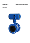
To avoid measuring errors due to gas/air entrainment or to a partly filled pipe, please observe the following:
Horizontal (standard) mounting
The sensor tube must always remain full. The best way to achieve this is to locate the sensor in a low
section of pipe, see the following picture. It is recommended to install the sensor in a section of straight
pipe with at least 5 times the pipe diameter before sensor and 3 times after sensor.
5 DN
3 DN
3 DN
5 DN
Pipe reducers
If the pipe diameter is not the same as the diameter of sensor, then pipe reducers can be used. So as not to
lose accuracy of the measurement, the slope of reducers should not exceed 8.
8
Operation manual
MEATEST
Battery operated magnetic flowmeter M930
8
Vertical mounting
When the sensor is mounted on a vertical section of pipe, the flow direction must be upwards. In the case of
a downward flow direction, air bubbles can collect in the sensor and the measurement could be unstable
and inaccurate.
Pumps
Never install the sensor on the suction side of a pump or on a section of pipe where a vacuum is possible.
Operation manual
9
Battery operated magnetic flowmeter M930
MEATEST
Valves
Suitable location of a shutoff valve is downstream of a sensor.
Removal during maintenance
If the application requires removal of the sensor for periodic maintenance, it is recommended to install a
bypass section as the following drawing.
Position of electrodes
The axis of measuring electrodes must be approximately horizontal (see picture).
YES
10
NO
Operation manual
MEATEST
Battery operated magnetic flowmeter M930
Vibration
To avoid mechanical damage protect both electronic unit and sensor against mechanical vibrations. When
strong vibrations are possible, both the input and output pipe must be mechanically fixed or the remote
version with a separate electronic unit should be used.
Overheating
To avoid overheating, the electronic unit should be protected against direct sunlight especially in areas with
a warm climate with ambient temperatures over 30 oC. If necessary a sunshade has to be mounted over the
electronic unit or a remote version with a separate electronic unit should be used.
3.2
Battery connection
The flowmeter is delivered with disconnected internal battery.
Following procedure should be used to connect battery after
installation the flowmeter.
Unscrew the back cover using the special wrench (standard
part of delivery).
Connect the 10 pin flat cable to the connector (highlighted in
the picture).
Screw on the back cover.
3.3
Battery replacing
The battery life time depends on excitation frequency, flowmeter settings and ambient temperature.
Terms shortening battery life:
Short excitation time
USB connecting
Active display
If the battery indicates low state, remove the battery by the following steps:
1) Activate MENU → SETUP → GENERAL → BATTERY → Change new (yes)
You will be prompted to inserting new battery.
2) Insert new battery
3) Check date and time
3.4
Electric connection between converter and sensor – Remote version
For remote version converter and flanged sensor are connected with two (2-wire unshielded and 3-wire
shielded) cables. Standard length of cables is 6 meter. It is recommended to mount the transmitter not too
far from the flanged sensor. Use cables as short as possible.
Five-terminal connector is located in separated box. The same
box is used for the converter and also for the sensor. Colours of
wires are following:
3-wire shielded
wire):
Blue (Brown) :
Green :
Red (White):
Operation manual
cable (shielding is connected to the green
Electrode 1 (EL1)
Ground
Electrode 2 (EL2)
11
Battery operated magnetic flowmeter M930
2-wire cable:
Brown :
White :
MEATEST
Excitation 1 (EXCITATION)
Excitation 2 (EXCITATION)
Following procedure should be observed to connect sensor cable to the transmitter or sensor:
Switch off power supply.
Dismount top cover of connection box. Four screws must
be removed.
Connect 5 wires to the connector.
As the basic protection of connection box is IP65 it is
important (in case you need better protection) to fill the
box (with connected wires) with reenterable insulating
and sealing compound. One piece of compound is
standard part of delivery. Using this technology will be
protection of transmitter IP67 and protection of sensor
IP68.
Mount the cover back.
Switch on power supply.
3.5
Sensor grounding
To ensure the correct operation of the flowmeter an earthing connection between the sensor and pipeline
must be made. The sensor is equipped with screw connection for an earthing wire. This screw has to be
connected to the flange on the pipeline. Use Copper wire to connect between the flange and the earth screw
on the sensor.
If the pipeline is manufactured from a non-electrically conductive material, or if the pipe is lined with a
similar material, special grounding rings must be installed between flanges.
Note:
The flowmeter must not be switched on, if the sensor is not connected /earthed to the rest of
pipeline!
Sensor grounding without grounding rings
12
Sensor grounding with grounding rings
Operation manual
MEATEST
4
4.1
Battery operated magnetic flowmeter M930
Electronic unit description
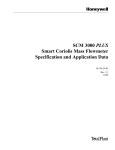
Front panel (display)
2
1
1
3
Capacitive buttons
Two capacitive buttons allows control of all flowmeter's functions. Buttons are activated by placing a
finger on isolated area. Both buttons has two levels of activation (short and long activation). Functions for
both levels are shown on display
Short activation – less than 0,7 s.
Long activation – more than 0,7 s
Example:
Top button: Short activation switches display to the next window.
Long activation resets auxiliary volume.
Bottom button: Short activation displays flow meter's MENU. There
is no function for long activation.
2
Display
Graphic LCD is used to display the total volume, instantaneous flowrate, actual function of capacitive
buttons and auxiliary information.
The type of units can be changed in the flowmeter “Setup Menu” (see chapter “Flowmeter configuration”).
Operation manual
13
Battery operated magnetic flowmeter M930
MEATEST
Output active
Empty pipe
USB connected
Service mode
Battery state:
< 100 %
< 80 %
< 40 %
< 30 % (blinking last
battery segment)
Description of the actual screen and the scroll bar.
If you don’t use the display for 30 s, display goes to sleep mode. The flowmeter continues with measuring.
Waking up is done by activating any button for 1 s.
3
USB connector
USB for connection the flowmeter to the computer. USB is electrically isolated from the flowmeter
electronics.
4.2
USB
The connector is located on the front panel and is accessible after removing the electronic unit cover. USB
enables you to connect the flowmeter to a personal computer. USB can be used for flowmeter's
configuration and calibration. It’s not suitable for online communication during operation, because the
flowmeter must be open (IP67 protection is lost).
Baud rate
Data bits
Stop bit
Parity
9600 Bd
8
1
none
For connection of the flowmeter to the PC a standard USB A-B cable is used. To
connect a PC to the flowmeter, follow this procedure:
Unscrew the front cover using the special wrench (standard part of delivery).
Plug the one end of the cable onto the USB connector in the flowmeter.
Connect the opposite end to the USB port in the PC.
Use the application software (FlowAssistant) to enter new calibration data or to change settings of the
flowmeter.
Disconnect USB cable and replace the cover.
Computer symbol is displayed during active USB communication.
Note:
14
USB port is galvanically isolated from other electronic circuits.
Operation manual
MEATEST
5
5.1
Battery operated magnetic flowmeter M930
Operation
Main menu
The flowmeter is in Main menu after the switching power on. This entire menu can be operated with
capacitive buttons without opening the housing.
The following information can be displayed in the Main Menu.
5.1.1
Total Volume
Basic display (after power on). Time is displayed on the
second line. Total volume is displayed on the second line.
Flow in the forward direction is added to this volume, Flow
in the reverse direction is subtracted. Measuring parameters
(units, moving average etc.) are selectable in Setup menu.
“Current Flowrate” is displayed after pushing “→” key.
5.1.2
Current Flowrate
Time is displayed on the first line. Current flowrate is
displayed on the second line. Measuring parameters (units,
moving average etc.) are selectable in Setup menu.
“Positive / Negative Volume” is displayed after pushing
“→” key.
5.1.3
Positive and Negative Volume
Total volumetric flow in a forward and a reverse direction.
“Auxiliary Volume” is displayed after pushing “→” key.
5.1.4
Auxiliary Volume
Second Total Volume counter. Value is cleared after
pushing “0” key (top button long activation). This operation
must be enabled in Setup menu. It is usually used for
measuring volumetric flow during a set period such as day,
month etc.. “Datalogger” is displayed after pushing” is
displayed after pushing “→” key.
5.1.5
Datalogger (periodical flow rate record)
Individual samples from datalogger memory can be read
after pushing “↓” key. In this submenu samples are read
sequentially. Next sample (Flowrate with Date and Time) is
displayed after pushing “↓” key. “Sequential reading”
submenu is left after pushing “→” key or after displaying
all values. “Current Flowrate / Total Volume” is displayed
after pushing “→” key. Datalogger capacity is 100 000
samples.
Operation manual
15
Battery operated magnetic flowmeter M930
MEATEST
Main menu windows are switched by pushing “→” key.
5.2
Internal backup system
Once an hour some data is saved to internal FLASH (Date and time, Total volume, Positive volume and
Negative volume). If you want change the battery, see “3.3 Battery replacing”. Menu settings, datalogger
etc. are saved immediately.
5.3
Menu - Basic rules (MENU)
Using the Setup menu can be changed all parameters of the flowmeter. Menu is organized as tree type
structure. Meaning of keys is:
„↑“
„OK“
„C“
- parameter selection
- confirmation of selected parameter
- return one level back
The folder names are written in capital letters, individual items are written small letters.
5.4
Setup menu (SETUP)
In this menu the flowmeter parameters can be changed. Access to the Setup menu is after pushing the
“MENU” key from the Main menu. Access is protected by password.
Correct password must be entered before entering Setup menu.
Without correct password the access to the Setup menu is refused.
Default factory password is “00000”. Password is entered by
pressing "↑", "→" keys and confirmed by pressing the "OK" key.
Return to the main menu is possible by pressing the "C" key.
After entering correct password the flowmeter displays actual access level for app. 3s. There are three
levels of access (according to the password):
1) BASIC – default value is 00000. This level allows changing user settings of the flowmeter.
2) CALIBRATION – default value is 10000. This level allows changing user settings and calibration
data.
3) SERVICE – only for service engineers.
5.4.1
Flowmeter configuration (FLOWMETER)
Item serves for the flowmeter configuration. After pushing “↓” key next item (“CALIBRATION “) is
selected. After pushing “OK” key following menu is displayed:
5.4.1.1
Flowrate parameters (FLOW)
Function enables you to set flowrate unit, resolution and other flowrate parameters.
5.4.1.1.1
Flowrate units (Unit)
This item allows to set flowrate units.
Available units are:
l/s
litres per second
m3/h
cubic metres per hour
UG/m US gallons per minute
IG/m imperial gallons per minute
16
Operation manual
MEATEST
User
5.4.1.1.2
Battery operated magnetic flowmeter M930
user-defined unit, factory-set is „l/h“ (litres per hour), user defined unit can be changed by
computer only
User unit name (User unit)
This item allows to set the name of user unit. Maximal length is five letters.
5.4.1.1.3
User unit conversion constant (User constant)
This item allows to set the conversion constant for user unit. This constant is calculated as the ratio between
flowrate in [l/s] and flowrate in [user unit]. CALIBRATION access is required.
5.4.1.1.4
Flowrate direction (Direction)
This item allows to switch between “Positive” and “Negative” flow direction (change the sign in flowrate
value).
Note:
5.4.1.1.5
Flowmeters are working in both flow directions. However standard calibration is made for
positive direction only.
Low-flow cutoff (Low-fl.off)
This item allows to set limit for suppressing low flowrates. Available range is according to the nominal
diameter.
Note:
5.4.1.1.6
All flowrates below this value will be displayed as 0.00. This setting is valid for display and all
outputs.
Coils excitation time (Excitation)
This items allows to set the time between flow measurement. The value has a significant impact on battery
life. Following frequencies can be set:
1s
5s
15 s
30 s
5.4.1.1.7
battery life 5 months
battery life 30 months
battery life 5 years
battery life 7 years
Moving average time constant (Time const.)
This item allows to change the time for moving average calculating. Available range is between 4 and 20 s.
5.4.1.1.8
Nominal flowrate range (RANGE )
Function enables you to change the nominal flowrate range. This is the auxiliary constant for easy
configuration of flowmeter’s outputs. There is no dependency between flowmeter’s accuracy and this
constant.
5.4.1.2
Volume parameters (VOLUME)
This item allows to set volume unit, resolution and other volume parameters.
5.4.1.2.1
Volume units (Unit)
This item allows to set volume units.
Available units are:
l
litres
m3
cubic metres
UG
US gallons
IG
US gallons
User
user-defined unit, factory-set is „l“ (litres), user defined unit can be changed by computer only
Operation manual
17
Battery operated magnetic flowmeter M930
5.4.1.2.2
MEATEST
User unit name (User unit)
This item allows to set the name of user unit. Maximal length is four letters.
5.4.1.2.3
User unit conversion constant (User constant)
This item allows to set the conversion constant for user unit. This constant is calculated as the ratio between
volume in [l] and volume in [user unit]. CALIBRATION access is required.
5.4.1.2.4
Resetting Volume counters (CLEAR VOLUME)
This item allows to clear volume counters.
“Auxiliary volume” clears auxiliary volume counter.
“Total volume” clears total volume counter (CALIBRATION access is required).
“Pos/Neg volume” clears positive and negative volume counter (CALIBRATION access is required).
5.4.1.3
Datalogger parameters (DATALOGGER)
This item allows to set the datalogger.
5.4.1.3.1
Datalogger sampling interval (Interval)
This item allows to set sample interval for internal datalogger. You can select one of following intervals:
Off, 5, 10, 15, 30, 45, 60, 120, 180 and 240. Values are expressed in minutes. Flowrate value written into
the datalogger is calculated as average value in the selected interval.
5.4.1.3.2
Datalogger filling (Filling)
This item displays datalogger filling in %. Datalogger capacity is over 100 000 samples.
5.4.1.3.3
Datalogger clear(Clear)
This item allows to clear the datalogger memory.
5.4.2
Calibration menu (CALIBRATION)
This item serves for the flowmeter calibration.
Setting any new value in calibration menu changes calibration data! Calibration
should be performed in an appropriate equipped laboratory.
We recommended using software FlowAssistant for easy Calibration. It contains
„calibration wizard“ and can prevent flowmeter from incorrect calibration.
You can change calibration values only if the correct calibration password has been entered. Default factory
setting is “10000”.
Note:
18
Flowmeter M930 enables calibration at 2, 3 or 4 points. Each calibration point contains 2 values.
Nominal value of calibration point is selected by user in range between +/- QMAX (for maximum
flowrates see table 1: M930 flowrates). It is expressed in flowrate units. To this nominal value is
attached a calibration constant. Calibration constant doesn’t have a unit. In the calibration
process you change this calibration constant to reach similarity between standard flowmeter and
the calibrated flowmeter. Higher calibration constant means lower displayed value.
Calibration constants must be different. In the case of two equal calibration constants, the
measured values could be wrong.
Operation manual
MEATEST
5.4.2.1
Battery operated magnetic flowmeter M930
Number of Calibration Points (Num.of cal.point)
This item allows to enter number of calibration points in range between 2 and 4.
Note:
5.4.2.2
Standard number of calibration points is 2. More calibration points are used for special
applications when higher accuracy is expected (negative flowrate, low flowrates etc.).
Calibration point 1 (CAL.POINT 1)
This item allows to change nominal and calibration value of Calibration point 1.
5.4.2.2.1
Flowrate nominal value setting (Flowrate)
Flowrate nominal value can be changed in the range +/- QMAX (see the table 1: M930 flowrates). This value
is flowrate that is calibrated.
5.4.2.2.2
Calibration constant (Constant)
Value presents calibration constant in above defined calibration point. Higher calibration constant means
lower displayed value.
5.4.2.3
Calibration point 2 (CAL.POINT 2)
This item allows to change nominal and calibration value of Calibration point 2. For detail description see
Calibration point 1.
5.4.2.4
Calibration point 3 (CAL.POINT 3)
This item allows to change nominal and calibration value of Calibration point 3. For detail description see
Calibration point 1.
5.4.2.5
Calibration point 4 (CAL.POINT 4)
This item allows to change nominal and calibration value of Calibration point 4. For detail description see
Calibration point 1.
5.4.2.6
Original calibration settings (Orig. cal. settings)
This item restores calibration settings on factory settings (Number of calibrations points, Calibration points
1-4, Range and Low flow cut-off)
5.4.3
General settings (GENERAL)
This item serves for flowmeter general settings.
5.4.3.1
Interface parameters (USB-RS232)
This item allows to change USB (virtual RS232) parameters.
5.4.3.1.1
Bus mode (Mode)
Following modes are available:
Normal
Modbus ASCII
Modbus RTU
5.4.3.1.2
Modbus parity (Modbus parity)
Following parity setting is available:
Operation manual
19
Battery operated magnetic flowmeter M930
MEATEST
None
Even
Odd
5.4.3.1.3
Modbus address (Modbus address)
Available range for modbus addresses is 1 to 247.
5.4.3.2
Display parameters (DISPLAY)
This item allows to change display parameters.
5.4.3.2.1
Language (Language)
This item allows to set the language. You can select one of following items: (Cestina, English).
5.4.3.2.2
Display contrast (Contrast)
This item allows to set the display contrast in range 30 to 70 %.
5.4.3.2.3
Message display time (Message time)
This item allows to set the message display time. You can select one of following items: (Short, Normal,
Long).
5.4.3.3
Real time setting (DATE/TIME)
This item allows to correct time of internal Real time clock and select required date format.
5.4.3.3.1
Time setting (Time set)
This item allows to set the actual time. Range is 00:00 to 23:59.
5.4.3.3.2
Date setting (Date set)
This item allows to set the actual date. Range is 01.01.2009 to 31.12.2099.
5.4.3.3.3
Date format setting (Date format)
This item allows to set required date format. You can select one of following items: („D/M/Y“, „D.M.Y“,
„D-M-Y“, „Y/M/D“, „Y.M.D“, „M/D/Y“, „M-D-Y“).
5.4.3.4
Password setting (USER ACCESS)
This item allows to set user passwords.
5.4.3.4.1
Basic access password (Basic password)
This item allows to set five digits password for access level “BASIC”.
5.4.3.4.2
Calibration access password (Calibr. password)
This item allows to set five digits password for access level “CALIBRATION”.
5.4.3.4.3
Clear on main screen(Clear. on screen)
This item allows to clear auxiliary volume and min./max. flowrates without password direct from the Main
menu. If item is enabled the password is not required.
5.4.3.5
Battery administration (BATTERY)
This item allows battery administration.
20
Operation manual
MEATEST
5.4.3.5.1
Battery operated magnetic flowmeter M930
Size of battery (Type)
This item allows to set size of battery pack. You can select one of following types: (2 cells, 4 cells).
5.4.3.5.2
Change new
This item use only if you want change battery. After select and confirm (yes) is activate battery
replacement.
5.4.3.6
Service information (INFO)
This item displays internal measured values. These values can be used for diagnostic.
5.4.3.6.1
Serial number (Serial number)
This item displays flowmeter’s serial number as ‘xxxxxx’ (six digits).
5.4.3.6.2
Firmware version (Version SW)
This item displays internal firmware version as ‘FW x.xx’.
5.4.3.6.3
Hardware version (Version HW)
This item displays internal hardware version as ‘HW x.xx’.
5.4.3.6.4
Nominal sensor diameter DN (Diameter)
This item displays nominal sensor diameter in mm. Diameter can be changed with access level
“SERVICE”.
5.4.3.6.5
Internal temperature (Int. temp)
This item measures internal temperature. Optimal range is -20 to 75 °C.
5.4.3.6.6
Battery voltage (Volt.battery)
This item measures battery voltage. Optimal range is 2.8 to 3.7 V.
5.4.3.6.7
CPU voltage (Volt. CPU)
This item measures CPU voltage. Optimal range is 2.8 to 3.2 V.
5.4.3.6.8
Internal voltage +5 V (Volt. high)
This item measures internal power supply +5 V. Optimal range is 4.7 to 5.1 V.
5.4.3.6.9
Internal voltage +3.6 V (Volt. +symm)
This item measures internal power supply +3.6 V. Optimal range is 3.5 to 3.7 V.
5.4.3.6.10
Internal voltage -3.6 V (Volt. -symm)
This item measures internal power supply -3.6 V. Optimal range is -3.5 to -3.7 V.
5.4.3.6.11
Reference voltage +2,5 V (Volt. ref)
This item measures internal reference. Optimal range is 2.4 to 2.6 V.
5.4.3.6.12
Coil excitation current(Coil excit)
This item measures coil excitation current. Optimal range is 22 to 24 mA.
Operation manual
21
Battery operated magnetic flowmeter M930
5.5
MEATEST
Nominal values (standard factory setting)
FLOWMETER
FLOW
UNIT
USER UNIT
USER CONSTANT
DIRECTION
EXCIT. TIME
L.F.CUTOFF
TIME CONSTANT
RANGE
m3/h
l/h
3600
Positive
1/15 Hz
flowrate Q1%/2
10s
flowrate Qn (nominal flowrate)
VOLUME
UNIT
USER UNIT
USER CONSTANT
m3
l
1.0
DATALOGGER
INTERVAL
Off
CALIBRATION
NUMBER OF CAL.P
2
CAL. POINT 1
FLOWRATE
CONSTANT
5 … 10 % of required Qn
is assigned according to the calibration
CAL. POINT 2
FLOWRATE
CONSTANT
40 … 70 % of required Qn
is assigned according to the calibration
CAL. POINT 3
Not used
CAL. POINT 4
Not used
GENERAL
INTERFACE
USB-RS232
MODE
MODBUS PARITY
MODBUS ADDRESS
Normal
Even
10
DISPLAY
LANGUAGE
22
English
Operation manual
MEATEST
Battery operated magnetic flowmeter M930
CONTRAST
MESSAGE TIME
50 %
Normal
DATE/TIME
ACTUAL TIME
ACTUAL DATE
DATE FORMAT
actual time (GMT + 1)
actual date (GMT + 1)
D/M/Y
USER ACCESS
BASIC PASSWORD
CAL. PASSWORD
CLEAR ON SCREEN
00000
10000
Enabled
INFO
DIAMETER
according to the sensor DN
6
System control
Flowmeter can be connected to the computer via USB bus. USB connector is located behind the front
panel. RS485 terminals are behind the back panel. In fact, the connected computer creates a virtual serial
port RS232 and utilities communicate with the layer RS232. Communication parameters must be set in
menu (item USB-RS232).
USB interface can work in three modes:
a) Normal – communication protocol ADAM compatible with flowmeter M910 and M920.
b) Modbus RTU – communication protocol Modbus, binary communication.
c) Modbus ASCII – communication protocol Modbus, ASCII communication.
To transfer data in Normal mode 8N1 data format is used, i.e. each data word includes 8 bits, no parity and
one stop bit. The communication speed can be set using the system menu. Available values: 1200, 2400,
4800, 9600 and 19200 Bd. Flowmeter in Modbus mode has its own modbus address. Range of this address
is from 1 to 247.
6.1
Command syntax
Communication between flowmeter and computer consists of a flow of periodically alternating commands
type command-response or query-response. Command is always a text followed by parameter and ended by
control sign <cr>. Response is always ended with control sign <cr>.
There are three types of responses:
1) Parameters value – response to a query
2) Ok – response to a command
3) ErrX – in case that command has wrong format. Where X is error code from the table below:
Error code
1
2
3
4
5
6
7
Meaning
Unknown command
Parameter out of range
Value cannot be set
Value cannot be read
Unknown parameter
Parameter too low
Parameter to high
Operation manual
23
Battery operated magnetic flowmeter M930
8
9
MEATEST
Number as parameter is required
Access denied – use appropriate password
Modbus protocol is explained in independent chapter.
Syntax description
<DNPD> =
Decimal Numeric Program Data, this format is used to express decimal number with or
without the exponent.
<CPD> =
Character Program Data. Usually, it represents a group of alternative character parameters.
e.g. {0 | 1 | 2 | 3}.
?=
A flag indicating a request for the value of the parameter specified by the command. No other
parameter than the question mark can be used.
(?) =
A flag indicating a request for the parameter specified by the command. This command
permits a value to be set as well as requested.
<cr> =
carriage return. ASCII code 13. This code executes the command or query.
6.2
6.2.1
Command list
Main menu
Flowrate reading
RFL?
Response contains actual “Flowrate” value in selected units.
Example:
If query „RFL?<cr>” is sent, flowmeter returns response in format „100.000<cr>“. Resolution is designed
by Setup menu.
Volume reading
RVO?
Response contains actual “Volume” counter value in selected units.
Example:
If query „RVO?<cr>” is sent, flowmeter returns response in format „100.000<cr>“. Resolution is designed
by Setup menu.
Positive volume reading
RVP?
Response contains actual Positive volume counter value.
Example:
If query „RVP?<cr>” is sent, flowmeter returns response in format „100.000<cr>“. Resolution is designed
by Setup menu.
Negative volume reading
RVN?
24
Operation manual
MEATEST
Battery operated magnetic flowmeter M930
Response contains actual Negative volume counter value.
Example:
If query „RVN?<cr>” is sent, flowmeter returns response in format „-100.000<cr>“. Resolution is designed
by Setup menu.
Auxiliary volume reading
RVA?
Response contains actual Auxiliary volume counter value.
Example:
If query „RVA?<cr>” is sent, flowmeter returns response in format „100.000<cr>“. Resolution is designed
by Setup menu.
6.2.2
Flowmeter
6.2.2.1
Flowrate parameters
Flowrate unit
FFS(?) <CPD> { 0 | 1 | 2 | 3 | 4 }
Following units can be set:
0
1
2
3
4
l/s
m3/h
UG/m
IG/m
“User”
M930 confirms execution with string „Ok<cr>”.
Example:
Command „FFS 0<cr>” sets flowrate unit “l/s”. If query „FFS?<cr>” is sent, flowmeter returns response in
format „0<cr>”.
Flowrate user unit
FFU(?) <CPD>
Command sets text for flowrate user unit.
<CPD>
It represents user units expressed as 5 ASCII characters. M930 confirms execution with string „Ok<cr>”. In
case of query M930 returns set user unit.
Example:
Command „FFU l/m <cr>” sets flowrate user unit “ l/m “. After query „FFU?<cr>” flowmeter returns
string „l/m <cr>”.
Conversion constant for flowrate user unit
FFC(?) <DNPD>
Command sets conversion constant for flowrate user unit with respect to [l/s].
<DNPD>
Operation manual
25
Battery operated magnetic flowmeter M930
MEATEST
It represents a constant, which is calculated as a ratio between flowrate in user unit and flowrate in basic
unit ( [l/s] ). For example constant for [m3/h] is 3.6. M930 confirms execution with string „Ok<cr>”. In
case of query M930 returns set constant.
Example:
Command „FFC 3.6<cr>” sets constant “3.6 “. After query „FFC?<cr>” flowmeter returns
„3.600000<cr>”.
Flowrate direction
FFD(?) <CPD> { 0 | 1 }
Following directions can be set:
0 Positive
1 Negative
M930 confirms direction with string „Ok<cr>”.
Example:
Command „FFD 0<cr>” sets “Positive direction”. If query „FFD?<cr>” is sent, flowmeter returns response
in format „0<cr>”.
Low flow cutoff
FLF(?) <DNPD>
Command sets flowrate limit for suppression low flowrates.
<DNPD>
It represents flowrate expressed in actual unit. All flowrates below this limit are displayed as 0. M930
confirms execution with string „Ok<cr>”. In case of query M930 returns set low flow cut-off.
Example:
Command „FLF 0.2<cr>” sets low flow cut-off “0.2“. After query „FLF?<cr>” flowmeter returns
„0.200000<cr>”.
Excitation setting
FEC(?) <CPD> { 0 | 1 | 2 | 3 }
Following frequencies can be set:
0
1
2
3
1s
5s
15 s
30 s
M930 confirms execution with string „Ok<cr>”.
Example:
Command „FEC 3<cr>” sets excitation 30s. In case of query „FEC?<cr>” flowmeter returns „3<cr>”.
Time constant
FTC(?) <DNPD>
Command sets time for moving average calculation.
<DNPD>
It represents time expressed in seconds. Any value in range between 4 second and 20 seconds can be set.
M930 confirms execution with string „Ok<cr>”. In case of query M930 returns time constant.
26
Operation manual
MEATEST
Battery operated magnetic flowmeter M930
Example:
Command „FTC 6<cr>” sets time constant “6“ seconds. After query „FLF?<cr>” flowmeter returns
„6<cr>”.
Min. / Max. flowrates Reset
CLRMM
Command resets “Min. Flowrate” and “Min. Flowrate” values.
M930 confirms execution with string „Ok<cr>”.
Example:
Command „CLRMM<cr>” resets both min/max values.
Nominal flowrate reading
RQN?
Response contains actual flowmeters Nominal flowrate (QN).
Example:
If query „RQN?<cr>” is sent, flowmeter returns response in format „80.00<cr>“ for nominal flowrate 80
(m3/h…).
6.2.2.2
Volume parameters
Volume unit
FVS(?) <CPD> { 0 | 1 | 2 | 3 | 4 }
Following units can be set:
0
1
2
3
4
m3
l
UG
IG
“User”
M930 confirms execution with string „Ok<cr>”.
Example:
Command „FVS 0<cr>” sets volume unit “m3”. If query „FVS?<cr>” is sent, flowmeter returns response in
format „0<cr>”.
Volume user unit
FVU(?) <CPD>
Command sets text for volume user unit.
<CPD>
It represents user units expressed as 5 ASCII characters. M930 confirms execution with string „Ok<cr>”. In
case of query M930 returns set user unit.
Example:
Command „FVU dm3 <cr>” sets volume user unit “dm3 “. After query „FVU?<cr>” flowmeter returns
string „dm3 <cr>”.
Conversion constant for volume user unit
FVC(?) <DNPD>
Operation manual
27
Battery operated magnetic flowmeter M930
MEATEST
Command sets conversion constant for volume user unit with respect to [l].
<DNPD>
It represents a constant, which is calculated as a ratio between volume in user unit and volume in basic unit
( [l] ). For example constant for [m3] is 0.001. M930 confirms execution with string „Ok<cr>”. In case of
query M930 returns set constant.
Example:
Command „FVC 0.001<cr>” sets constant “0.001 “. After query „FVC?<cr>” flowmeter returns
„0.001000>”.
Total volume counter Reset
CLRVO
Command resets “Total volume counter” including the positive and negative volume counter.
M930 confirms execution with string „Ok<cr>”.
Example:
Command „CLRVO<cr>” resets the Total volume counters.
Positive and negative volume counter Reset
CLRVM
Command resets “Pos/Neg volume counter” including the positive and negative volume counter.
M930 confirms execution with string „Ok<cr>”.
Example:
Command „CLRVM<cr>” resets the Positive and negative volume counters.
Auxiliary volume counter Reset
CLRAV
Command resets “Auxiliary volume counter”.
M930 confirms execution with string „Ok<cr>”.
Example:
Command „CLRAV<cr>” resets the Auxiliary volume counter.
6.2.2.3
Datalogger parameters
Datalogger step
DST(?) <CPD> { 0 | 1 | 2 | 3 | 4 | 5 | 6 | 7 | 8 | 9 }
Datalogger can be set:
0
1
2
3
4
5
6
7
8
9
28
Datalogger is Off
Datalogger sampling rate is 5 minutes.
Datalogger sampling rate is 10 minutes.
Datalogger sampling rate is 15 minutes.
Datalogger sampling rate is 30 minutes.
Datalogger sampling rate is 45 minutes.
Datalogger sampling rate is 60 minutes.
Datalogger sampling rate is 120 minutes.
Datalogger sampling rate is 180 minutes.
Datalogger sampling rate is 240 minutes.
Operation manual
MEATEST
Battery operated magnetic flowmeter M930
M930 confirms datalogger step with string „Ok<cr>”.
Example:
Command „DST 0<cr>” switches datalogger “Off”. If query „DST?<cr>” is sent, flowmeter returns
response in format „0<cr>”.
Datalogger number of samples
DNR?
Response contains number of flowrate samples stored in datalogger.
Example:
If query „DNR?<cr>” is sent, flowmeter returns response in format „252<cr>“ for 252 samples in
datalogger.
Datalogger filling (percentage)
DPC?
Response contains datalogger filling in percent.
Example:
If query „DPC?<cr>” is sent, flowmeter returns response in format „14<cr>“ for 14% datalogger full.
Datalogger filling (bytes)
DBT?
Response contains datalogger filling in bytes.
Example:
If query „DBT?<cr>” is sent, flowmeter returns response in format „1850<cr>“ for 1850 bytes used.
Datalogger reading (text format)
DRT?
Response contains all values stored in internal datalogger.
Example:
If query „DRT?<cr>” is sent, flowmeter returns response in format:
14:28 13.10.2003
14:33 13.10.2003
14:38 13.10.2003
14:43 13.10.2003
14:48 13.10.2003
No Record
5.82
4.76
4.72
4.72
4.70
l/s
l/s
l/s
l/s
l/s
Datalogger reading (hex format)
DRD?
Response contains all values stored in internal datalogger.
Example:
If query „DRD?<cr>” is sent, flowmeter returns response in intel hex format:
Datalogger clear
DCLR
Operation manual
29
Battery operated magnetic flowmeter M930
MEATEST
Command clears all data stored in internal datalogger.
M930 confirms execution with string „Ok<cr>”.
Example:
Command „DCLR<cr>” clears all data in datalogger.
30
Operation manual
MEATEST
6.2.3
Battery operated magnetic flowmeter M930
Calibration
Number of calibration points
CPN(?) <CPD> { 2 | 3 | 4 }
M930 confirms completion with string „Ok<cr>”.
Example:
Command „CPN 2<cr>” sets mode 2 calibration points. If query „CPN?<cr>” is sent, flowmeter returns
response in format „2<cr>”.
Nominal value of calibration point 1
CX1(?) <DNPD>
Command sets constant CX1, which represents the nominal value of calibration point 1.
<DNPD>
It represents nominal value in selected units. M930 confirms completion with string „Ok<cr>”. In case of a
query the M930 returns the set value in the selected unit.
Example:
Command „CX 110.5<cr>” sets value CX1 to 10.5. After query „CX1?<cr>” flowmeter returns string
„10.500000<cr>”.
Nominal value of calibration points 2, 3 and 4
CX2, CX3, CX4
For explanation see command CX1.
Calibration constant for calibration point 1
CY1(?) <DNPD>
Command sets constant CY1, which represents the calibration constant for calibration point 1.
<DNPD>
It represents the calibration constant. M930 confirms completion with string „Ok<cr>”. In case of a query
the M930 returns the set value.
Example:
Command „CY 110.5<cr>” sets value CY1 to 10.5. After query „CY1?<cr>” flowmeter returns string
„10.500000<cr>”.
Calibration constants for calibration points 2, 3 and 4
CY2, CY3, CY4
For explanation see command CY1.
6.2.4
6.2.4.1
General
Display parameters
Contrast setting
FDC (?) <CPD> { 0 | 1 | 2 | 3 | 4 }
Operation manual
31
Battery operated magnetic flowmeter M930
MEATEST
Display contrast setting:
0
1
2
3
4
30 %
40 %
50 %
60 %
70 %
M930 confirms completion with string „Ok<cr>”.
Example:
Command „FDC 2<cr>” sets 50%. If query „FDC?<cr>” is sent, flowmeter returns response in format
„2<cr>”.
Message time setting
FDM(?) <CPD> { 0 | 1 | 2 }
You can select one of following items:
0
1
2
Short
Normal
Long
M930 confirms completion with string „Ok<cr>”.
Example:
Command „FDM 2<cr>” sets the message time to “Long”. If query „FDM?<cr>” is sent, flowmeter returns
response in format „2<cr>”.
Language setting
FLG(?) <CPD> { 0 | 1 }
You can select one of following items:
0
1
English
Cestina
M930 confirms completion with string „Ok<cr>”.
Example:
Command „FLG 0<cr>” selects language “English”. If query „FLG?<cr>” is sent, flowmeter returns
response in format „0<cr>”.
6.2.4.2
Real time clock setting
Time setting
FTM(?) <CPD> HH:MM
Command sets new time for internal Real Time Clock.
<CPD>
It represents new time in format HH:MM:SS. Any value in range between 00:00 and 23:59 can be set.
M930 confirms execution with string „Ok<cr>”. In case of query M930 returns real time.
Example:
Command „FTM 14:25<cr>” sets new time (2:25 pm). After query „FTM?<cr>” flowmeter returns
„14:25<cr>”.
32
Operation manual
MEATEST
Battery operated magnetic flowmeter M930
Date setting
FDT(?) <CPD> DD.MM.YYYY
Command sets new date for internal Real Time Clock.
<CPD>
It represents new date in format DD.MM.YYYY. Any value in range between 01.01.2000 and 31.12.2099
can be set. M930 confirms execution with string „Ok<cr>”. In case of query M930 returns real date.
Example:
Command „FDT 05.03.2002<cr>” sets new date (March 5, 2002). After query „FDT?<cr>” flowmeter
returns „05.03.2002<cr>”.
Date format setting
FDF(?) <CPD> { 0 | 1 | 2 | 3 | 4 | 5 | 6 }
You can select one of following items:
0
1
2
3
4
5
6
M/D/Y
M-D-Y
D/M/Y
D.M.Y
D-M-Y
Y/M/D
Y.M.D
M930 confirms completion with string „Ok<cr>”.
Example:
Command „FDF 0<cr>” sets the date format “D/M/Y”. If query „FDF?<cr>” is sent, flowmeter returns
response in format „0<cr>”.
6.2.4.3
Password setting
Password
PSW <DNPD>
Command enters password, that enables access to flowmeter’s settings. Password can be change with new
command PSW.
Example:
Command „PSW 12345<cr>” enters password 12345.
Actual access level
PAL(?) <CPD> { 0 | 1 | 2 | 3 }
Command can set the access level to 0. Query returns the actual access level.
Available levels:
0
1
2
3
Without access
Basic access level
Calibration access level
Service access level
Example:
If query „PAL? <cr>” is sent flowmeter returns response in format “2<cr>”, for “Calibration access level”.
Command „PAL0<cr>“ sets the flowmeter to access level 0 (without access).
Operation manual
33
Battery operated magnetic flowmeter M930
MEATEST
Direct reset from the Main menu
FME(?) <CPD> { 0 | 1 }
Command enables the possibility to reset Auxiliary volume and Min. / Max. flowrate direct from the Main
menu (without password).
One of following states can be set:
0
1
Disabled
Enabled
M930 confirms completion with string „Ok<cr>”.
Example:
Command „FME 1<cr>” enables direct reset from the Main menu. If query „FME?<cr>” is sent, flowmeter
returns response in format „1<cr>”.
Basic access password setting
FPB(?) <DNPD>
Command changes the password valid for access level “Basic”.
<DNPD>
Presents new password in range 0 to 99999. M930 confirms completion with string „Ok<cr>”.
Example:
Command „FPB 520<cr>” sets basic password “520”. If query „FPB?<cr>” is sent, flowmeter returns
response in format „520<cr>”.
Calibration access password setting
FPC(?) <DNPD>
Command changes the password valid for access level “Calibration”.
<DNPD>
Presents new password in range 0 to 99999. M930 confirms completion with string „Ok<cr>”.
Example:
Command „FPC 520<cr>” sets calibration password “520”. If query „FPC?<cr>” is sent, flowmeter returns
response in format „520<cr>”.
6.2.4.4
Service information
Device identification
IDN?
*IDN?
Response contains flowmeter’s model type number.
Example:
If query „IDN?<cr>” is sent, flowmeter returns response in format „„M930-V0000,360001,1.00<cr>“.
Nominal diameter reading
RDN?
Response contains actual flowmeter’s Nominal diameter (DN).
Example:
If query „RDN?<cr>” is sent, flowmeter returns response in format „50<cr>“ for nominal diameter 50mm.
34
Operation manual
MEATEST
Battery operated magnetic flowmeter M930
Battery’s capacity reading (percentage)
BAT?
Response contains actual battery’s capacity.
Example:
If query „BAT?<cr>” is sent, flowmeter returns response in format „50<cr>“ for capacity 50%.
6.2.4.5
Error messages
Errors reading
IER?
Response contains list of all errors from the power on or from the last reading (query IER?).
The Mask allows selecting which errors will be reported via the State Output. Errors are expressed as sum
of bit values of errors. Bit value of possible errors is in the table:
Bit
D0
D1
D2
D3
D4
D5
D6
Bit value
1
2
4
8
16
32
64
Error
Battery voltage overload
Internal voltage overload
Excitation open
Empty pipe
Datalogger full
Temperature over
Flash erasing over
Example:
Response „0<cr>” indicates that there was no error. Response “16<cr>“ indicatesdatalogger full. Value
“12<cr>” (8+4) indicates that excitation circuit is open and there is no liquid in the pipe (empty pipe).
Flowmeter’s state reading
RES?
Response contains flowmeter’s state.
Response is:
0
1
- flowmeter measures without correct
- flowmeter indicates error (in the last 3 seconds before the query was sent)
Example:
If query „RES?<cr>” is sent, flowmeter returns response in format „0<cr>“
Operation manual
35
Battery operated magnetic flowmeter M930
7
MEATEST
Error messages
When any error occurs, the flowmeter will display an error message. Errors can arise because of:
Incorrect control, i.e. faulty connection to the flowmeter, grounding, etc.,
Flowmeter failure
In case of any error, the error message is displayed on the display for approx. 1 to 5 seconds. The same
error message can be read by computer (command IER?).
After switching on, an internal test of the hardware is performed. If there were any error during the power
on test, the flowmeter displays the appropriate error message.
Types of errors and methods of troubleshooting (if available) are in following table.
Nr
Error
Meaning
Troubleshooting
110 FLASH over
Internal memory error.
Internal error. Turn the flowmeter off and after 5 s turn on.
If the error will appear again, contact manufacturer.
120 Temperature
error
Ambient temperature
error.
121 Int. voltage
Internal voltage error.
Internal error. Turn the flowmeter off and after 5 s turn on.
If the error will appear again, contact manufacturer.
122 Excitation open
Resistance of excitation
coils is higher than 250
Ohm.
Resistance of excitation coils is too high (open circuit).
Check sensor connection.
125 Empty pipe
No liquid in pipe
130 Datalogger full
Memory of datalogger is
full.
Fill the pipe with liquid. In case there is liquid in the pipe,
clean electrodes and check connection cables between
sensor and electronic.
Read the datalogger using the Flow Assistant software.
Except of errors mentioned above the flowmeter reports also errors caused by incorrect communication
with the computer. These errors are described in the chapter „Remote control“.
36
Operation manual
MEATEST
8
Battery operated magnetic flowmeter M930
Maintenance
The inductive flowmeter is an electronic device with circuits protected with built-in electronic fuses. These
protect the instrument against damage caused by the user.
8.1
Advice for correct operation
The following principles should be consider during installation:
Protect the flowmeter and the internal lining of the sensor pipe from mechanical damage, especially
during installation or cleaning.
Protect the flowmeter from direct sunlight. Fit a sunshade if necessary.
Do not expose the flowmeter to intense vibration.
8.2
Periodical maintenance
The flowmeter does not require any special maintenance. Dependent on the media being measured it is
recommended that approx. once a year, remove the sensor from the pipe and clean the liner. Method of
cleaning consists of removing mechanical dirt and any non-conductive coating (like oil film) from the liner.
A very dirty liner could cause inaccuracy of the measurement. Check mechanical state of the liner.
8.3
What to do in case of failure
If an obvious failure occurs during the operation (e.g. the display is not lit), the flowmeter must be
switched off immediately.
Remove the cover from the transmitter
Disconnect the power supply battery (see chapter Battery connection)
Connect power supply again.
Replace the cover.
If an obvious fault is evident, e.g. a measurement range or an operating mode is not functional, the user
cannot correct the fault.
Hidden faults can cause different symptoms. Usually, they cause instability of some parameters. Hidden
defects can be caused by unacceptable distortion, degraded insulation etc. In this case contact Distributor.
The flowmeter can have “hidden defects”, when correct operation rules are not applied. In this case, the
fault can be caused by wrong installation. Most frequent cases of false “hidden defects”:
mains voltage out of tolerance limits or unstable
poor grounding of the measuring circuit (bad connection of the ground terminal )
large electrostatic or electromagnetic field.
Operation manual
37
Battery operated magnetic flowmeter M930
9
MEATEST
Application information
9.1
Weight and dimensions
Flowmeter weight and dimensions depend mostly on the version (remote or compact) and diameter of the
pipe.
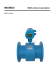
9.1.1
Electronic unit – compact version
The pictures below show dimensions of the electronic unit for the compact version. Dimensions are in
millimetres.
230
181
124
148
Weight: 3.8 kg
9.1.2
Electronic unit – remote version
The picture shows dimensions of the electronic unit for the remote version. Dimensions are in millimetres.
230
185
60
38
70
155
Weight: 5.1 kg
Operation manual
MEATEST
9.1.3
Battery operated magnetic flowmeter M930
Sensor
In the table below are the dimensions of the sensor for compact version. In case of remote version add 120
millimetres to dimension “A” for cable gland and cable. Flanges in DIN version meet standard EN1092.
Flanges in ANSI version meet requirements of ANSI B 16.5 standard.
DN (mm)
10
15
20
25
32
40
50
65
80
100
125
150
200
250
PN (bar)
16
16
16
16
16
16
16
16
16
16
16
16
16
10
D (mm)
90
95
105
115
140
150
165
185
200
220
250
285
340
395
A (mm)
140
145
150
155
165
175
185
200
215
235
265
295
355
435
L (mm)
150
200
200
200
200
200
200
200
200
250
250
300
350
450
Weight (kg)
2,5
3
3,5
4
5
5
7
8,5
10
13
17
22
31
44
Table 1: M930 dimensions and weights – DIN flanges
Operation manual
39
Battery operated magnetic flowmeter M930
9.2
MEATEST
Used materials
Electromagnetic flowmeter is made from materials, which meet international standards and conventions.
Liner:
Hard rubber
Teflon - PTFE
as standard
Electrodes
CrNi (stainless) steel 1.4571
Hastelloy C276
Tantalum
as standard
Sensor tube
Stainless steel 1.4201,
dimensions according to DIN 17457
Flange
Steel 1.0402 or higher,
dimensions according to EN1092, DIN2501(=BS 4504),
ANSI B16.5, Sanitary DIN11851,
flangeless wafer style
40
Operation manual
MEATEST
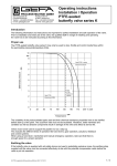
9.3
Battery operated magnetic flowmeter M930
Flowrate versus diameter
The choice of flowrate for an electromagnetic flowmeter depends on the diameter of the sensor. The higher
pipe diameter, the higher flowrate can be measured. A determining parameter for flowrates is maximum
velocity of the liquid. Maximum velocity is the speed, where the flow of liquid inside pipe is still laminar.
In M930 it is limited to 10m/s (with 125% overload). Speed over 10 m/s is usually too high for industrial
applications. Such diameter of pipe is usually selected, where expected flowrate is between Q 5% and Q50%.
In the table bellow applicable flowrates for various diameters is displayed in units l/s and m3/hr.
Flowrates [ l/s ]
Flowrates [ m3/h ]
DN
Q1%
Q5%
QN
Q50%
Q100%
QMAX
Q1%
Q5%
QN
Q50%
Q100%
QMAX
10
15
20
25
32
40
50
65
80
100
125
150
200
250
0,01
0,02
0,03
0,05
0,08
0,1
0,2
0,3
0,5
0,8
1
2
3
5
0,04
0,09
0,16
0,25
0,40
0,6
1,0
1,7
2,5
3,9
6
9
16
25
0,20
0,50
0,90
1,40
2,20
4,0
6,0
9,0
14,0
20,0
30,0
50,0
100
150
0,39
0,88
1,57
2,45
4,02
6,3
9,8
16,6
25,1
39,3
61
88
157
245
0,79
1,77
3,14
4,91
8,04
12,6
19,6
33,2
50,3
78,5
123
177
314
491
0,98
2,21
3,93
6,14
10,05
15,7
24,5
41,5
62,8
98,2
153
221
393
614
0,03
0,06
0,11
0,18
0,3
0,5
0,7
1,2
1,8
3
4
6
11
18
0,14
0,32
0,57
0,88
1,5
2,3
3,5
6,0
9,0
14
22
32
57
88
0,80
2,00
3,20
5,00
8,00
13,0
20,0
35,0
50,0
80
150
200
300
500
1,41
3,18
5,65
8,84
14,5
22,6
35,3
59,7
90,5
141
221
318
565
884
2,83
6,36
11,31
17,67
29,0
45,2
70,7
119,5
181,0
283
442
636
1131
1767
3,53
7,95
14,14
22,09
36,2
56,6
88,4
149,3
226,2
353
552
795
1414
2209
Q1%
Q5%
QN
Q50%
Q100%
QMAX
- minimum applicable flowrate (minimum flowrate with guaranteed accuracy)
- recommended minimum flowrate (minimum flowrate with best accuracy)
- recommended nominal flowrate (expected working flowrate)
- recommended maximum flowrate (maximum flowrate for industrial use)
- maximum applicable flowrate (maximum flowrate with guaranteed accuracy)
- maximum applicable overload (Q125%) (flowmeter is still measuring)
Table 2: M930 flowrates
A sensor diameter should be chosen to keep real flowrate between Q 5% and Q50%, because in this range the
flowmeter has the best accuracy.
Operation manual
41
Battery operated magnetic flowmeter M930
MEATEST
10 Type plate
Compact version
The type plate is located on the sensor. The following information is on the plate:
Flow direction
Type
M930-V0000
Zelezna 509/3
619 00 Brno
www.meatest.com
DN / PN:
S.n.:
Year:
Q:
IP 67
100 / 16
310541
2009
0..80 m3/h
DN – nominal diameter
(10 … 800 mm)
PN – nominal pressure
(6 … 25 x100kPa)
Serial
number
Production Year
Flowrate range
Protection
Manufacturer
42
Operation manual
MEATEST
Battery operated magnetic flowmeter M930
Remote version
Type plate on the flanged sensor:
Flow direction
Type
M930-V0001
Zelezna 509/3
619 00 Brno
www.meatest.com
DN / PN:
S.n.:
Year:
Q:
100 / 16
310541
2009
0..80 m3/h
IP 67
DN – nominal diameter
(10 … 800 mm)
PN – nominal pressure
(6 … 25 x100kPa)
Serial
number
Production Year
Flowrate range
Protection
Manufacturer
Type plate on the converter:
Type
M930-V0001
Zelezna 509/3
619 00 Brno
www.meatest.com
S.n.:
Year:
IP 65
310541
2009
Serial
number
Production Year
Protection
Manufacturer
Operation manual
43
Battery operated magnetic flowmeter M930
MEATEST
11 Technical data
Nominal size
DN10 to DN250
Nominal pressure
PN10 to PN40 (depending on nominal size)
Flow range
Minimum electrical conductivity
0.1 to 12 m/s (0.01 to 600 l/s) / (0.03 to 2100 m3/h)
0.5 % (0.5 to 12 m/s) of reading value
1 % (0.1 to 0.5 m/s)
0 to 80oC (32 to 176oF) for rubber liner
0 to 150oC (32 to 302oF) for PTFE liner in remote version
5 S / cm
Ambient temperature
-20 to 60 C (-4 to 140F)
Excitation coils temperature
-20 to 150 C (-4 to 302F)
Power supply
Internal battery
hard rubber
soft rubber
PTFE
CrNi (stainless) steel 1.4571
Hastelloy C276
Tantalum
Accuracy
Maximum media temperature
Liner
Electrodes
Measuring tube
Flange
Protection category
Communication
Displayed values
Control
Other features
44
Stainless steel 1.4201, dimensions according to DIN 17457
Steel 1.0402 or higher
Dimensions according to EN1092, DIN2501 (BS 4504), ANSI B16.5,
Sanitary DIN11851, flangeless wafer style
Compact version: IP67
Remote version: sensor IP68, converter IP65- optionally IP67
USB (Modbus)
Flowrate (m3/h, l/s, US.Gal/min, Imperial.Gal/min, user)
Volume (m3, l, US.Gal, Imperial.Gal, user)
Positive, total, negative and auxiliary (clearable, daily) volume
Capacitive buttons
USB
Test of: excitation coils, sensor, electronic unit
Internal temperature and power supply diagnostic
Real time clock
Empty pipe indication
Datalogger 100000 records (programmable sample rate)
Registration of min. and max. flowrate including date and time
Operation manual
MEATEST
Battery operated magnetic flowmeter M930
12 Ordering information - options
Liner
M930-V0xxx
M930-V1xxx
M930-V2xxx
hard rubber
soft rubber
teflon PTFE
Electrodes
M930-Vx0xx
M930-Vx1xx
M930-Vx2xx
CrNi steel
hastelloy C276
tantalum
Construction
M930-Vxxx0
M930-Vxxx1
compact version
remote version
12.1 Example of order
M930-V0000 DN50 PN16
Liner: hard rubber
Electrodes: CrNi steel
Construction: compact version
Nominal diameter: 50 mm
Nominal pressure: 16 bar
M930-V2120 DN15 PN25
Liner: PTFE
Electrodes: hastelloy C276
Construction: compact version
Nominal diameter: 15 mm
Nominal pressure: 25 bar
Operation manual
45
Battery operated magnetic flowmeter M930
MEATEST
13 Terminology
Special symbols and terms.
Flowrates:
Q1%
- minimum applicable flowrate (the least flowrate which has guaranteed measuring accuracy –
depends on diameter – see table 2 M930 flowrates).
Q5%
- recommended minimum flowrate (least flowrate which has the best measuring accuracy –
depends on diameter – see table 2 M930 flowrates).
QN
- recommended nominal flowrate (nominal flowrate in which is flowmeter usually calibrated –
depends on diameter – see table 2 M930 flowrates). You can predetermine this nominal flowrate in
your order.
Q50% - recommended maximum flowrate (maximum flowrate which is usually used in industrial
applications – depends on diameter – see table 2 M930 flowrates).
Q100% - maximum applicable flowrate (flowrate limit which has guaranteed measuring accuracy –
depends on diameter – see table 2 M930 flowrates).
QMAX - maximum applicable overload (Q125%) (maximum flowrate which can be still measured –
depends on diameter – see table 2 M930 flowrates).
Abbreviations:
QP
- impulse output constant. It represents volume for 1 impulse.
PF1
- flowrate limit constant. It represents low limit flowrate. Crossing this limit activates the
appropriate digital output.
PF2
- flowrate limit constant. It represents high limit flowrate. Crossing this limit activates the
appropriate digital output.
H
- flowrate limit constant. It represents hysteresis by evaluating limits PF1 and PF2.
Auxiliary volume counter – second Total Volume counter. Can be cleared by pushing “→” key. It is
usually used for measuring volume during day, month etc.
USB – universal serial bus. It enables remote control of instruments by a computer.
46
Operation manual
MEATEST
Battery operated magnetic flowmeter M930
Appendix A Measuring principle
The flowmeter is designed for electrically conductive fluids. Measurement is based on Faraday’s law of
induction, according to which a voltage is induced in an electrically conductive body, which passes through
a magnetic field. The following expression is applicable to the voltage:
U=KxBxvxD
where:
U = induced voltage
K = an instrument constant
B = magnetic field strength
v = mean velocity
D = pipe diameter
Thus the induced voltage is proportional to the mean flow velocity, when the field strength is constant.
Inside the electromagnetic flowmeter, the fluid passes through a magnetic field applied perpendicular to the
direction of flow. An electric voltage is induced by the movement of the fluid (which must have a
minimum
electrical conductivity). This is proportional to the mean flow velocity and thus to the volume of flow. The
induced voltage signal is picked up by two electrodes, which are in conductive contact with the fluid and
transmitted to a signal converter for a standardized output signal. This method of measurement offers the
following advantages:
No pressure loss through pipe constriction or protruding parts.
Since the magnetic field passes through the entire flow area, the signal represents a mean value over
the pipe cross-section; therefore, only relatively short straight inlet pipes x DN from the electrode axis
are required upstream of the primary head.
Only the tube liner and the electrodes are in contact with the fluid.
Already the original signal produced is an electrical voltage, which is an exact linear function of the
mean flow velocity.
Measurement is independent of the flow profile and other properties of the fluid.
The magnetic field of the primary head is generated by a square wave current fed from the signal converter
to the field coils. This field current alternates between positive and negative values. Alternate positive and
negative flowrate-proportional signal voltages are generated at the same frequency by the effect of the
magnetic field, which is proportional to the current. The positive and negative voltages at the primary head
electrodes are subtracted from one another in the signal converter. Subtraction always takes place when the
field current has reached its stationary value, so that constant interference voltages or external or fault
voltages changing slowly in relation to the measuring cycle are suppressed. Power line interference
voltages coupled in the primary head or in the connecting cables are similarly suppressed.
Operation manual
47
Battery operated magnetic flowmeter M930
MEATEST
Appendix B M930 Menu structure
M930 has three access levels for parameter’s setting:
Basic (user access)
Calibration (calibration laboratory)
Service (service organization)
Every parameter has minimal access level which allows you to change it.
Access to parameters is enabled after pushing the key “ENTER” from the Main menu and after entering the
password. Access level is defined by used password.
Setup menu has following folders:
- FLOWMETER
- CALIBRATION
- GENERAL
- SERVICE
FLOWMETER
FLOW
VOLUME
Unit
User unit
User constant
Direction
Low-fl. off
Exc. freq
Time const.
Range
Unit
User unit
User Constant
CLEAR VOLUME
Auxiliary volume
Total volume
Pos/Neg volume
DATALOGGER
CALIBRATION
Num.of cal.point
CAL. POINT 1
CAL. POINT 2
CAL. POINT 3
CAL. POINT 4
GENERAL
USB-RS232
DISPLAY
DATE/TIME
USER ACCESS
48
Interval
Filling
Clear
Flowrate
Constant
Flowrate
Constant
Flowrate
Constant
Flowrate
Constant
Orig. cal. settings
Mode
Modbus parity
Modbus address
Language
Contrast
Message time
Time set
Date set
Date format
Basic password
Calibr. password
Clear. on screen
Operation manual
MEATEST
Battery operated magnetic flowmeter M930
INFO
Serial number
Version SW
Version HW
Diameter
Int. temp
Volt. battery
Volt. CPU
Volt high
Volt. +symm
Volt. –symm
Vol. ref
Coil excit
SERVICE
Manufacturer
MEATEST, spol.s r.o.
Zelezna 509/3, 619 00 Brno
Czech Republic
www.meatest.com
Operation manual
tel: +420 – 543 250 886
fax: +420 – 543 250 890
[email protected]
49