1
MODEL SR560
LOW-NOISE PREAMPLIFIER
1290-D Reamwood Avenue
Sunnyvale, CA 94089 U.S.A.
(408) 744-9040
Copyright © 1989, 1990, 1997, 1999, 2011, 2013
Stanford Research Systems
All Rights Reserved.
Revision 3.0
(8/2013)
TABLE OF CONTENTS
Introduction and Setup
Instrument Overview
Preparation for Use
Line Voltage
Line Fuse
Line Cord
Ventilation
Power-Up
Repackaging for Shipment
Use in Biomedical Applications
Warning Regarding Use with Photomultipliers
Accessories Furnished
Environmental Conditions
Symbols
1
2
2
2
2
2
2
3
3
3
3
3
4
Specifications
SR560 Low Noise Preamplifier Specifications Chart
5
Operation and Controls
Front Panel Operating Summary
Power
Source
Filters
Gain Mode
Gain
Output
Reset
Status
Rear Panel Operating Summary
AC Power Input
Amplifier Power Output
Battery Charger
Blanking Input
RS-232 Interface
Battery Care and Usage
Recharging
Battery Care
7
7
7
8
9
9
9
9
9
10
10
10
10
11
11
11
11
11
Circuit Description
Differential Low-Noise Front End
Configurable Filters and Gain
Output Stages
Overload Detection
Microprocessor
Battery Charger and Pre-regulators
Power Regulators
Rear Panel Interfaces
Batteries and P.E.M.
Front Panel
13
13
13
14
14
14
15
15
16
16
i
TABLE OF CONTENTS
Calibration and Repair
Offset Adjustment
Calibration
Front End Replacement
SR560 Offset Adjustment Procedure
Battery Replacement
Fuse Replacement
Noise Contours
Input Voltage Noise
Dynamic Reserve
17
17
17
18
18
18
19
20
20
Appendix A
Remote Programming
Introduction
Commands
A-1
A-1
A-1
Appendix B
Noise Sources and Cures
Intrinsic Noise Sources
Johnson Noise
'1/f' Noise
Others
Non-Essential Noise Sources
Capacitive Coupling
Inductive Coupling
Resistive Coupling ('Ground Loops')
Microphonics
Thermocouple Effect
B-1
B-1
B-1
B-1
B-1
B-1
B-2
B-2
B-3
B-3
B-3
SR560 - Component List
Front Panel Board
Main Board
Miscellaneous Parts
C-1
C-2
C-13
D-1
PCB - SR560 Revision F (9/89)
E-1 to E-10
Schematics
ii
INTRODUCTION AND SETUP
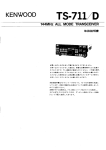
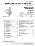
Figure 1: SR560 Block Diagram
INSTRUMENT OVERVIEW
BNC amplifier" with the amplifier ground
isolated from the chassis and the AC power
supply. Opto-isolated input blanking control
and listen-only RS-232 interface lines are
provided for instrument control. Digital
noise is eliminated by shutting down the
microprocessor's oscillator except during
the short time required to alter the
instrument's configuration, either through a
front-panel pushbutton or through an RS232 command. Internal sealed lead-acid
batteries provide 15 hours of line-
The SR560 architecture is diagrammed
above. The instrument provides DCcoupled low-noise amplification of singleended and true differential input signals at
gains of 1 to 50,000. Two configurable R-C
filters are provided to selectively condition
signals in the frequency range from DC to 1
MHz. The user can choose high dynamic
reserve or low noise settings, and can invert
the output relative to the input. The SR560
normally operates with a fully floating
ground and can be viewed as an "in-line-
1
INTRODUCTION AND SETUP
independent operation. Rear panel banana
jacks provide access to the internal
regulated power supplies (or batteries) for
use as a bias source.
Line Fuse
Verify that the correct line fuse is installed
before connecting the line cord to the unit.
For 100 V and 120 V, use a 1 Amp fuse and
for 220 V and 240 V, use a 1/2 Amp fuse.
PREPARATION FOR USE
**********CAUTION**********
Line Cord
This instrument may be damaged if
operated with the LINE VOLTAGE
SELECTOR card set for the wrong applied
AC input source voltage or if the wrong fuse
is installed.
The SR560 has a detachable, three-wire
power cord with a three-contact plug for
connection to both the power source and
protective ground.
The protective ground
connects to the accessible metal parts of
the instrument except for BNC shields.
To prevent electrical shock, always
use a power source outlet that has a
properly grounded protective-ground
contact.
Line Voltage
When the AC power cord is connected to
the unit and plugged into an AC outlet, the
unit automatically switches the amplifier
power source from internal battery operation
to line operation. The internal batteries are
charged as long as AC power is connected.
Ventilation
Always ensure adequate ventilation when
operating the SR560. The unit will generate
heat while charging dead batteries.
The SR560 can operate from a 100 V, 120
V, 220 V or 240 V nominal AC power source
having a line frequency of 50 or 60 Hz.
Before connecting the power cord to a
power source, verify that the LINE
VOLTAGE SELECTOR card, located in the
rear-panel fuse holder of the unit, is set so
that the correct AC input voltage value is
visible.
Power-Up
All instrument settings are stored in
nonvolatile memory (RAM backed-up) and
are retained when the power is turned off.
They are not affected by the removal of the
line cord. If the power-on self test passes,
the unit will return to the settings in effect
when the power was last turned off. If an
error is detected or if the backup battery is
exhausted, the default settings will be used.
Additionally, if the RESET key is held down
when the power is turned on, the instrument
settings will be set to the defaults shown
below:
Conversion from one AC input voltage to
another requires a change in the fuse
holder's LINE VOLTAGE SELECTOR card
position and a new fuse. Disconnect the
power cord, slide the fuse holder cover to
the left and rotate the fuse-pull lever to
remove the fuse. Remove the small printed
circuit board. Select the operating voltage
by orienting the printed circuit board. Press
the circuit board firmly into its slot, so the
desired voltage is visible. Rotate the fusepull lever back into its normal position and
insert the correct fuse into the fuse holder.
2
Parameter
Setting
SOURCE
COUPLING
INVERT
Channel A
DC
OFF
INTRODUCTION AND SETUP
ROLLOFF
HIGH-PASS
LOW-PASS
GAIN MODE
GAIN
LISTEN
DEVICE ADDRESS
bypassed
0.03 Hz, +6 dB/oct
1 MHz, -6 dB/oct
High Dynamic
Reserve
20, calibrated
ON
As per SW601
Accessories Furnished
- Power cable
- Operating Manual
Environmental Conditions
OPERATING
Temperature: 10°C to 40°C
Relative Humidity: <90% Non-condensing
Repackaging for Shipment
The original packing materials should be
saved for reshipment of the SR560. If the
original packing materials are not available,
wrap the instrument in polyethylene
sheeting or equivalent and place in a strong
box, cushioning it on all sides by at least
three inches of high-density foam or other
filler material.
NON-OPERATING
Temperature: -25°C to +65°C
Relative Humidity: <95% Non-condensing
Warning regarding battery
maintenance
Batteries used in this instrument are seal
lead acid batteries. With usage and time
these batteries can leak. Always use and
store this instrument in the feet-down
position. To prevent possible damage to the
circuitboard, it is recommended that the
batteries be periodically inspected for any
signs of leakage.
Use in Biomedical Applications
Under certain conditions, the SR560 may
prove to be unsafe for applications involving
human subjects. Incorrect grounding,
component failure, and excessive commonmode input voltages are examples of
conditions in which the instrument may
expose the subject to large input currents.
Therefore, Stanford Research Systems
does not recommend the SR560 for such
applications.
Warning Regarding Use with
Photomultipliers
The front-end amplifier of this instrument is
easily damaged if a photomultiplier is used
improperly with the amplifier. When left
completely unterminated, a cable connected
to a PMT can charge to several hundred
volts in a relatively short time. If this cable
is connected to the inputs of the SR560, the
stored charge may damage the front-end
FETs. To avoid this problem, provide a
leakage path of about 100 kΩ to ground
inside the base of the PMT to prevent
charge accumulation.
3
4
SPECIFICATIONS
SR560 LOW-NOISE PREAMPLIFIER SPECIFICATIONS CHART
Inputs
Single-ended or true differential
Impedance
100 M + 25 pF, DC-coupled
Maximum Inputs
1 VDC before overload; 3 V peak to peak max AC coupled;
protected to 100 VDC
Maximum Output
10 Vpp
Noise
<4 nV/Hz at 1 kHz
CMRR
>90 dB to 1 kHz, decreasing by 6 dB / octave (20 dB / decade)
above 1 kHz
Gain
1 to 50,000 in 1-2-5 sequence
vernier gain in 0.5% steps
Flatness
±0.3dB to 300kHz
(gains up to 1000)
-3 dB at 1 MHz, 1 Vpp output
Gain Stability
200 ppm /°C
DC Drift
5 V/°C referred to input (DC coupled)
Filters
0.03 Hz to 1 MHz, 10% typical accuracy
Distortion
0.01% typical
Power
100, 120, 220, 240 VAC (50/60 Hz), 60 Watts Max
Internal Batteries: 3 x 12 V, 1.9 Ah sealed
lead-acid (rechargeable)
±12 VDC in / out through rear panel banana jacks.
Battery Life
15 hours nominal
250-1000 charge / discharge cycles
Charge Time
4 hours to 80% of capacity
Mechanical
1/2 Rack-Mount width, 3 1/2" height, weight 15 lbs.
Dimensions
14-7/8" x 8-1/8" x 3-1/2"
Warranty
1 year parts and labor on materials and workmanship
5
SPECIFICATIONS
6
OPERATION AND CONTROLS
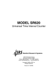
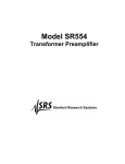
Figure 2: SR560 Front Panel
FRONT PANEL OPERATING SUMMARY
lighted. As the batteries near exhaustion,
this indicator will change from green to red,
indicating that the unit should be connected
to AC power to charge the batteries.
The operation of the SR560 Low-Noise
Preamplifier has been designed to be as
simple as possible. The effect of each
keypress on the front panel is reflected in
the change of a nearby LED. The front
panel LED’s will remain lighted at all times
unless dip switch SW601 (accessible
through the bottom cover of the unit)
positions 3 and 4 are placed in the "off"
position. All front panel functions can be
controlled through the rear-panel RS-232
interface.
When connected to an AC power source,
amplifier power is derived from regulated
line power, and the internal batteries are
automatically charged. When operating on
AC power, the front panel "LINE" indicator is
on to indicate the source of amplifier power.
Charging status is indicated on the rear
panel by the "CHARGE" and "MAINTAIN"
LED indicators.
Power
Source
The SR560 is turned on by depressing the
POWER switch. When disconnected from
AC power, the unit will operate for
approximately 15 hours on internal sealed
lead-acid batteries. Up to 200 mA of
unregulated battery power is available at the
rear panel banana jacks as long as the
power switch is in the ON position. Battery
life will be reduced when the unit is
providing external power through the rear
panel jacks. When operating on batteries,
the front panel "BATT" indicator will be
There are two input connectors located in
the SOURCE section of the front panel.
The pushbutton located between them
selects either single-ended (A or B) or
differential (A-B) inputs.
The A and B inputs are voltage inputs with
100 MΩ, 25 pF input impedance.
Their
connector shields are completely isolated
from chassis ground, but can be made
7
OPERATION AND CONTROLS
MHz. The filters in the FILTER CUTOFFS
section can be configured in the following
six ways:
common with chassis ground by connecting
the "AMP GROUND" and "CHASSIS
GROUND" banana jacks on the rear panel
of the SR560. When connected to AC
power, the chassis of the unit is always
connected to the grounding conductor of the
AC power cord. The inputs are protected to
100 VDC but the DC input should never
exceed 10 Vp. The maximum DC input
before overload is 1 V peak.
i. high-pass filter at +12 dB / octave
ii. high-pass filter at +6 dB / octave
iii. high-pass filter at +6 dB / octave,
and low-pass filter at -6 dB /
octave (band-pass)
iv. low-pass filter at -6 dB / octave
v. low-pass filter at -12 dB / octave
vi. no filters in the signal path
The COUPLING pushbutton selects the
method of connecting the A and B inputs to
the amplifier. The inputs can be AC (0.03
Hz - 3 dB) or DC-coupled, or the inputs to
the amplifier can be internally grounded with
the A and B input BNC’s left floating. This
feature makes for simple offset nulling,
particularly useful when operating the
amplifier DC-coupled at high gains. Please
refer to CALIBRATION AND REPAIR -OFFSET ADJUSTMENT for information on
the offset nulling procedure.
The filter settings are controlled by the
ROLLOFF, HIGH-PASS and LOW-PASS
pushbuttons. Each time the ROLLOFF
pushbutton is pressed the instrument
configures the two R-C filters to conform to
the progression shown above. The four
ROLLOFF LED’s give a visual indication of
the current filter configuration. For the
HIGH-PASS filter the left pushbutton serves
to decrease its cutoff frequency. The two
pushbuttons for the LOW-PASS filter
function in an analogous manner.
NOTE: When the coupling is set to AC, a
0.03 Hz cutoff high-pass filter is always
engaged. All high-pass filter modes can still
be selected while AC-coupled, but the 0.03
Hz filter will always be in, even if the filters
are set to DC. Because one of the two filter
sections is always used as a high pass
when AC coupling is selected, low-pass
filters are only available with a 6 dB / octave
rolloff.
When the FILTER CUTOFFS section is
configured solely as high-pass or low-pass
(i, ii, iv and v ), the cutoff frequency is
illuminated by one of sixteen LED’s in the
range from 0.03 Hz to 1 MHz, and the slope
of the rolloff is shown by one of the four
ROLLOFF LED’s. When the filter section is
configured as band-pass (iii), the cutoff
frequencies are illuminated by two LED’s.
The frequency setting on the left marks the
cutoff for the high-pass filter, and the setting
on the right is the cutoff for the low-pass
filter. The two 6 dB / oct ROLLOFF LED’s
are also illuminated. In this case the two
cutoffs can be set to the same frequency to
provide a narrow bandpass. When both
filters are removed from the signal path (vi)
all rolloff and cutoff frequency LED’s are
extinguished from the FILTER CUTOFFS
section and the DC LED is on.
The INVERT pushbutton allows the user to
invert the output of the instrument with
respect to the input when operating with
single-ended or differential inputs. The
INVERT LED displays the output sense
relative to the input for all SOURCE
settings.
Filters
The SR560 contains two identical 1st-order
R-C filters whose cutoff frequencies and
topology (high-pass or low-pass) are
controlled from the front panel. The
maximum bandwidth of the instrument is 1
NOTE: High pass filters are not available
for the four highest frequency settings. See
the note under Source: Coupling for
8
OPERATION AND CONTROLS
information on using filters with the amplifier
in AC coupled mode.
Output
The outputs of the instrument are located
within the OUTPUT section of the front
panel. Two insulated BNCs are provided: a
600Ω output and a 50Ω output. The
amplifier normally drives high impedance
loads and the instrument's gain is calibrated
for high impedance loads. When driving a
600Ω load via the 600Ω output (or a
50Ω load via the 50Ω output) the gain of the
amplifier is reduced by two. The shields of
all the front-panel BNC’s are connected
together and form the amplifier's floating
ground.
Gain Mode
The allocation of gain throughout the
instrument is set using the GAIN MODE
pushbutton The Gain Mode is displayed by
two indicator LED’s: HIGH DYNAMIC
RESERVE and LOW NOISE. For a given
gain setting, a HIGH DYNAMIC RESERVE
allocates the SR560's gain toward the
output stages after the filters. This prevents
signals, which are attenuated by the filters
from overloading the amplifier. The LOW
NOISE setting allocates gain toward the
front-end in order to quickly "lift" low-level
(nV range) signals above the instrument's
noise floor.
Reset
The OVLD LED indicates a signal overload.
This condition can occur when a signal is
too large or the dynamic reserve is too low.
Reducing the gain, reducing the input signal
and/or switching to the HIGH DYNAMIC
RESERVE setting should remedy this
condition. If an overload occurs with filter
settings of long time constants, the RESET
pushbutton will speed the SR560's recovery
from overload.
Gain
The instrument's gain is increased or
decreased using the GAIN pushbuttons.
Gain settings from 1 to 50,000 are available
and are displayed as the product of a factor
1, 2 or 5 and a multiplier (none (i.e. 1), 10,
100, 1,000 or 10,000). In addition to these
fifteen fixed gain settings, the user may
specify arbitrary gains through the UNCAL
feature. To set an uncalibrated or arbitrary
gain the user must press both Gain buttons
simultaneously, lighting the UNCAL LED. In
this mode by pressing the Gain Up or Gain
Down pushbuttons, the user may reduce the
calibrated gain in roughly 1% increments
from 100% down to 0% of the selected gain.
In contrast to other front-panel functions,
when in UNCAL the instrument's key-repeat
rate will start slowly and increase to a limit
as long as either Gain button is depressed.
Simultaneously pressing both Gain buttons
once again will restore the unit to the
previously calibrated gain setting, and turn
off the UNCAL LED.
Status
The ACT LED indicates communications
activity over the SR560's optoisolated RS232 port. Please refer to Appendix A:
Remote Programming for further details on
programming the instrument via RS-232.
The BLANK LED indicates the optoisolated
BLANKING input (on the rear panel of the
SR560) is active. The SR560 responds to a
blanking input by internally grounding the
amplifier signal path after the front end and
before the first filter stage.
9
OPERATION AND CONTROLS
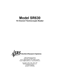
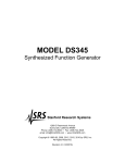
Figure 3: SR560 Rear Panel
REAR PANEL OPERATING SUMMARY
ground is connected to the AC line ground
conductor.
The SR560 rear panel is pictured in Figure
3. Various interface and power connectors
are provided, along with fuses and charger
status LEDs.
Battery Charger
AC Power Input
The two 3 A slow-blow fuses protect the
battery supply and charging circuitry. If
these fuses are blown, battery power will be
unavailable, and charging of the batteries
will not be possible.
The power entry module contains the
receptacle for the AC line cord and fuse.
The line fuse should be a 1 A slow-blow for
100/120 VAC operation, or a 1/2 A slowblow for 220/240 VAC operation.
When both the positive and negative supply
batteries are dead, the red "CHARGE" LED
will be on brightly, and the batteries will be
charging at a fast rate. When the batteries
approach a fully charged condition, the
charging current will be reduced to complete
the charge and maintain the batteries.
Because the batteries charge at different
rates, the indicators on the rear panel can
reflect the charge status of the positive and
negative batteries independently. When
one set of batteries switches to the
"MAINTAIN" mode, the red "CHARGE" LED
will be reduced to half brightness, and the
yellow "MAINTAIN" LED will turn on at half
brightness. When both batteries switch to
"MAINTAIN", the red "CHARGE" LED will
Amplifier Power Output
The -12 V, +12 V, and AMP GROUND
banana jacks provide external DC power up
to 200 mA for use as a bias source
referenced to the amplifier's floating power
supplies.
The CHASSIS GROUND banana jack is
provided to allow the amplifier's ground to
be referenced to the chassis. If the unit is
connected to an AC power source via a
three prong grounding plug, the chassis
10
OPERATION AND CONTROLS
the batteries from the amplifier if the unit is
operated for too long in the low battery
condition. This protects the batteries from
permanent damage, which could occur if
they were to remain connected to a load
while dead.
turn off and the yellow "MAINTAIN" LED will
be on full brightness.
Blanking Input
The blanking input accepts a TTL-level
signal and grounds the amplifier signal path
after the front end for as long as the input is
held high. The response time of the
blanking input is typically "on" 5 µs after the
rising edge and "off" 10 µs after the falling
edge.
The internal battery charging circuitry of the
SR560 will automatically charge dead
batteries at a quick rate until they are
approximately 80% charged. The charge
rate is then lowered to a level that is safe for
maintaining the batteries. During AC
operation, the batteries will be in this
"maintain" charge condition indefinitely, and
will suffer no degradation from prolonged
charging. The sealed lead-acid batteries
used in the SR560 differ in this respect from
nickel-cadmium batteries, which do suffer
shortened lifetimes due to overcharging.
The sealed lead-acid batteries will provide
the longest service life if they are not
allowed to discharge too deeply and if they
are charged immediately after use.
RS-232 Interface
The RS-232 interface connector allows
listen-only communication with the SR560
at 9600 baud, DCE. Communication
parameters should be set to 8 bits, no
parity, 2 stop bits. Data sent must be
delimited by <CR> <LF>. All front panel
functions excluding power and blanking, are
available over the RS-232 interface. For
more information on programming and
commands, see Appendix A: Remote
Programming.
Battery Care
WARNING: As with all rechargeable
batteries, for safety reasons the chemical
recombination processes within the cells
require that the batteries be allowed to vent
non-corrosive gases to the atmosphere.
Always use the batteries in an area with
adequate ventilation.
BATTERY CARE AND USAGE
The SR560 can be powered from either an
AC power source or from three 12 V, 1.9
Amp-hour maintenance-free sealed leadacid rechargeable batteries. Integral to the
SR560 is an automatic battery charger,
along with battery protection and charge
indication circuitry.
As with all instruments powered by
rechargeable batteries, the user must take
some precautions to ensure long battery
life. Understanding and following the
precautions outlined below will result in a
long operating life for the batteries in the
SR560.
Recharging
During battery operation, the front panel
BATT LED will change from green to red to
indicate that the batteries are low and
require charging. For the longest battery
life, the batteries should be immediately
charged by plugging the unit into AC power
whenever the BATT indicator lights red.
Internal protection circuitry will disconnect
The SR560's internal lead-acid batteries will
have a variable service life directly affected
by THE NUMBER OF DISCHARGE
CYCLES, DEPTH OF DISCHARGE AND
AMBIENT TEMPERATURE. The user
should follow these simple guidelines below
to ensure longest battery life.
11
OPERATION AND CONTROLS
• AVOID DEEP DISCHARGE
• KEEP THE BATTERIES COOL
Recharge the batteries after each use. The
two-step fast-charge / trickle-charge
operation of the SR560 allows the charger
to be left on indefinitely. ALWAYS recharge
the batteries immediately after the BATT
indicator LED on the SR560 turns red.
Built-in protection circuitry in the unit
removes the batteries from the load once a
dead-battery condition is detected.
Avoiding deep discharge will provide the
longest battery life - upwards of 1,000
charge / discharge cycles.
When not in use, the SR560 should be
stored in a cool, dry place with the batteries
fully charged. This reduces the selfdischarge of the batteries and ensures that
the unit will be ready for use when called
upon. A SR560 in storage should be
"topped off" every three months with an
overnight charge to maintain its batteries in
peak condition.
• AVOID TEMPERATURE EXTREMES
Batteries used in this instrument are seal
lead acid batteries. With usage and time
these batteries can leak. Always use and
store this instrument in the feet-down
position. To prevent possible damage to the
circuitboard, it is recommended that the
batteries be periodically inspected for any
signs of leakage.
Warning regarding battery maintenance
When using battery power, operate the
SR560 at or near room temperature.
Operating at lower temperatures will reduce
the capacity of the batteries. As well, more
time will be required to recharge the
batteries to their rated capacity. Higher
temperatures accelerate the rate of
reactions within the cell, reducing cell life.
12
CIRCUIT DESCRIPTION
select either the output of the second stage
amplifier or ground as the input to the next
stage, the first filter section.
DIFFERENTIAL LOW-NOISE
FRONT END
Two high-impedance inputs A and B allow
the instrument to operate in either singleended or true differential modes. Relays
K103 and K104 allow the inputs A and B to
be individually grounded, while K101 selects
AC or DC coupling. Inversion of the inputs
is provided by relay K105. The input
capacitances and R101 and R102 establish
the front end's input impedance at 25 pF
and 100 MΩ.
CONFIGURABLE FILTERS AND
GAIN
The two filter stages in the SR560 each
consist of 16 R-C filters which can be
configured as either high pass or low pass
by a relay. In the following description, part
references in parentheses refer to filter two.
Relay K201, (K301) selects either the highpass or low-pass configuration for all of the
sixteen filters. The output of one R-C
section is selected by multiplexer U202 or
U203, (U301 or U302) and passed on to
non-inverting buffer U202, (U303).
U106 is an NPD5564 low-noise matched
FET pair, which, along with U102 and U103
form the first differential amplifier stage.
U102 compares the currents in the drain
loads of U106, and U103 maintains the sum
of those currents at a fixed level by varying
the total current in both FETs. C109
provides open-loop compensation for U102,
and front-end gain is nominally established
by the sum of R118 and R112 over the sum
of R114 and R128. K102 is a gain switching
relay which selects a front end gain of 2 or
10. In the gain of 2 position, gain to the
next stage becomes 1 when R116 divides
with the input attenuator to the next stage.
For a gain of 10, relay K102 shorts the top
of R115 and R128 together, essentially
eliminating them from the gain loop. P103
allows adjustment of front-end offset, and
P104 allows for offset compensation when
in the low gain configuration. P102 allows
adjustment of the front-end common-mode
rejection ratio, along with P101, which
adjusts the CMRR in the low gain
configuration.
Approximately 80 pF input capacitance of
the multiplexers is included in the
calculation of the R-C time constants of the
filters. The four highest frequency stages
are not available as high-pass filters
because of unacceptable attenuation of the
signal that occurs when the filter
capacitance forms a divider with the input
capacitance of the multiplexers.
DG444 U205D, (U401A) is used to bypass
the filter sections entirely and U101D,
(U304D) is used to "reset" the filter stages
by discharging them through R228, (R329).
U201, (U305) is the third, (fourth) gain stage
with a fixed gain of 5. The input attenuator
U205, (U304) allows setting the gain of
these stages to 1, 2, or 5 under computer
control.
In the second gain stage, U105 is
configured with a fixed gain of 10. By
switching the input attenuation of this stage
with DG444 U101, the overall gain of this
stage can be computer selected as 2, 5, or
10. C111 provides high frequency
compensation for U105. The output of this
stage passes through all three sections of
U104, a CMOS multiplexer that serves as
the blanking control. The three parallel
switches provide a low "on" resistance to
OUTPUT STAGES
The fifth gain stage consists of op-amp
U402 which is configured as a non-inverting
amplifier with a gain of 5. U401 is a DG444
that again serves to switch the input
attenuation of this stage for overall gains of
1, 2, or 5. Additionally, output offset
13
CIRCUIT DESCRIPTION
panel key is pressed and instrument
settings are to be changed, or while there is
activity on the RS-232 port.
adjustment is provided by this stage.
U405B, half of an AD7528 dual 8-bit DAC is
used to provide a ±5 volt offset voltage at
the non-inverting input of U402. The front
panel offset control also sums at this
junction, and provides an offset voltage of
±5 V that is buffered by U407D.
The SR560 uses a 16 K x 8 CMOS
EPROM, (U504) containing system
firmware and calibration bytes, along with a
2 K x 8 CMOS RAM, (U505) which is
battery backed-up at all times to retain
instrument settings.
Following amplifier U402 is the other half of
the 8-bit DAC U405A, which along with opamp U404 forms a digital gain vernier. This
vernier is used in calibration to compensate
for gain variances that occur with
configuration changes such as input
coupling and filter settings. This DAC also
provides the front panel "uncal" gain vernier
function.
U507 generates port strobes for system IO,
and U510 provides a buffered data bus.
The buffered data bus is active only during
IO instructions to keep digital noise in the
amplifier to a minimum while the processor
is running.
U601 through U606 are control latches
providing the 48 DC control lines that
configure all of the instrument's hardware.
U607 is an input buffer and takes data from
the front panel and RS-232, as well as
providing a processor input indicating line
operation and address from SW601 for
ganged RS-232 operation. SW601
additionally controls power to the front panel
LED’s through positions 3 and 4.
The sixth and final gain stage consists of
U403 and output buffer U406, configured for
a gain of 5 and with input attenuator U409
to select overall gains of 1, 2, or 5. The
LM6321, (U406) provides the output drive
capability for both the 600Ω and 50Ω
outputs.
OVERLOAD DETECTION
The overload detector constantly monitors
the front-end output, filter 1 output, U402
(after the second filter) output, and final
stage output for excessive signal levels.
Comparator U408 compares both positive
and negative signal excursions against a 5
volt reference and lights the front panel
overload indicator if any levels are
excessive.
BATTERY CHARGER
AND PRE-REGULATORS
The 17 volt AC line transformer provides
unregulated power for both amplifier
operation and battery charging. Diode
bridge D706 and filter capacitors C706 and
C707 generate unregulated DC that is preregulated to ±12 VDC by U706 and U707 to
take the place of the batteries when the
instrument is operating on AC line power.
Relay U705 switches the amplifier from
battery to pre-regulated AC whenever the
AC line cord is plugged in.
MICROPROCESSOR
The system processor U503 is a CMOS Z80
processor running at 4 MHz. The system
clock consists of Schmitt trigger U506A and
an R-C network. The oscillator is designed
so that latch U508A can shut down the
clock oscillator completely, thereby
disabling all digital circuits in the amplifier so
that no digital noise will be present. The
processor and clock only run when a front
Diode bridge D710 and C709 and C710
provide unregulated DC to charge the
batteries. U701 and U702 operates as "AC"
regulators, limiting peak battery charging
voltage. As there are two positive batteries
and one negative battery, U701 is a LM350
14
CIRCUIT DESCRIPTION
regulator that provides twice the current of
the LM317 negative battery regulator.
POWER REGULATORS
The +5 V and +10 V supplies are produced
with three-terminal regulators U801 and
U802, respectively. The -10 V supply is
constructed of op-amp U803 and Q801, a
N-channel MOSFET as the pass element.
The +10 V supply serves as the reference
for the -10 V supply through divider R807
and R806.
Charging is controlled by changing the set
voltage of the regulators based on battery
charge status. Flip-flop U703 determines
whether the charge regulators will be set to
15.5 volts for a quick charge or 13.8 volts
for a trickle or "maintain" charge by
grounding the bottom of P701 and P702.
C712 and R704 insure that the charger
always powers up in the "quick" charge
mode. P701 and P702 are provided to
adjust the open circuit trickle charge voltage
to 13.8 volts. D701 and D703 are blocking
diodes for the charging circuits while not
charging, and D707 and D708 are clamps to
guard against battery polarity reversal.
The power output banana jacks on the rear
panel (J801 and J803) are connected to the
pre-regulated voltages after the power
switch and before the regulators. This
output can provide up to 200 mA of power
for use as an external bias source, etc.
Under some conditions, these jacks may be
used to supply the unit with external DC
power.
Comparators U708 and U709 are LP365
micropower comparators that monitor the
battery voltage. A resistive divider chain
sets the four trip points for each comparator.
D709 provides a stable 2.5 volt reference
against which levels are compared. For
each battery, three level indications are
provided, and are decoded by multiplexer
U704. The "trip" level is 14.5 volts. The trip
outputs control the state of U703 and switch
the battery charge voltage settings. The
"low" level is 11.3 volts and activates the
front panel low battery indicator. R730
provides some level hysteresis for the low
battery indication to prevent oscillation
around the trip point. The "dead" level is
10.7 volts and is used to disconnect the
load from the batteries before they are
damaged by an excessively deep
discharge. Q701 and Q703 are power
MOSFET switches used to disconnect
battery power from the amplifier. Dead level
hysteresis is provided by R724. R731 and
D711 provide un-interrupted battery power
to the system RAM so that stored
instrument settings are retained when the
power is switched off.
U506D and U506B generate the TTL level
input to the processor to indicate when the
unit is operating on the AC line.
Capacitors C801 through C821 are logic
supply bypass capacitors distributed
throughout the printed circuit board.
REAR PANEL INTERFACES
Two optically isolated rear panel interfaces
are provided on the SR560. The blanking
input accepts a TTL-level signal and
grounds the amplifier signal path after the
front end for as long as the input is held
high. The response time of the blanking
input is typically "on" 5 µs after the rising
edge and "off" 10 µs after the falling edge.
The RS-232 interface allows calibration and
control of the instrument at 9600 baud.
Data in and out on the connector are tied
together, echoing data back to the sender.
Hardware handshaking lines CTS, DSR,
and CD are tied to DTR. Refer to
Appendix A-1 for information on remote
programming of the SR560.
15
CIRCUIT DESCRIPTION
BATTERIES AND P.E.M.
FRONT PANEL
The batteries used in the SR560 are of
sealed lead-acid construction. There are
three 12 V, 1.9 amp-hour batteries, two of
which serve as the positive power supply,
and one of which serves as the negative
power supply. Powering the SR560 alone,
battery life should be greater than 20 hours.
The batteries should last for more than 1000
charge / discharge cycles, provided the
guidelines under the Usage section are
followed. Two 3A, fast blow fuses on the
rear panel protect the battery supplies and
amplifier against excessive currents.
The front panel contains the keypad
pushbuttons, LED indicators and serial shift
registers. The front panel pushbuttons are
decoded in a 3 x 4 matrix fashion. The front
panel LEDs are controlled by shift registers
U1 through U5, which allow the 5 eight-bit
control bytes to be serially shifted-in one bit
at a time. The red overload LED is
controlled directly from the output of the
overload comparator.
The battery LED is a dual-color LED that is
green when the unit is operating on battery
power, and turns red when the low_batt
signal is asserted.
The power entry module (P.E.M.) contains
the AC line fuse, RFI filter, and voltage
selection card. To change the operating
voltage of the unit, the voltage selector
printed circuit card must be pulled out and
reinserted into the P.E.M. with the desired
operating voltage visible.
The front panel output offset pot P1 is also
mounted on the front panel printed circuit
board.
16
CALIBRATION AND REPAIR
OFFSET ADJUSTMENT
The SR560's front-panel offset adjustment
provides an easy way for the user to null the
amplifier's DC offset. Use the COUPLING
pushbutton to light the GND LED. Now,
regardless of the SOURCE setting, the input
to the amplifier is grounded internally.
Insert a small screwdriver through the frontpanel OFFSET hole and adjust the offset
potentiometer until the DC offset of the
amplifier (e.g. as viewed on a DVM) is zero.
Finally, return to the desired coupling.
There are four pots, which are used to
calibrate the instrument. The pots adjust
the front-end CMRR (Common Mode
Rejection Ratio) and offset. These pots are
located close to the front of the instrument,
and may be accessed by removing the
bottom cover.
•
Couple = DC, source = A - B: adjust
P102 to null sine wave output.
•
Couple = GND (remove signal from
A and B inputs), Gain = 5 k, HIGH
DR: adjust P104 to null DC and
output.
•
Apply 1 kHz 1 Vpp sine to both the A
and B inputs.
•
Couple = DC, source = A - B: adjust
P101 to null sine wave output.
NOTE: In the above procedures, the gain of
the front-end (x10 or x2) is determined by
the selection of LOW NOISE or HIGH
DYNAMIC RESERVE.
These pots should be adjusted to optimize
the CMRR or null the offset when the frontend FET is replaced. Two of the pots adjust
the CMRR and offset when the front-end
gain is x10, and two adjust the CMRR and
offset when the front-end gain is x2. The
x10 gain pots must be set first, followed by
the x2 gain pots.
FRONT END REPLACEMENT
The most commonly damaged component
is the front-end FET (U106, National
Semiconductor Corp. P/N NPD5564). It is
located in an 8-pin DIP socket behind the
relays near the input BNCs. If the
instrument exhibits a constant overload,
excessive drift or noise, or large input bias
currents, it is likely that this component has
been damaged.
First, the front panel offset pot must be set
to zero:
Adjust front panel Offset pot to read
0 VDC on pin 14, U407.
When replacing the FET, be certain that all
eight pins are inserted into the socket, and
observe the orientation of pin #1. After
replacement adjust the CMRR and offset
per the calibration procedure. More severely
damaged front-ends may require
replacement of op-amp, U102.
Next adjust the offset and CMRR for the
case where the front-end gain is x10. View
the amplifier output on a scope and perform
the following adjustments:
•
Apply 1 kHz 1 Vpp sine to both the A
and B inputs.
Now adjust the offset and CMRR for the
case where the front-end gain is x2. View
the amplifier output on a scope and perform
the following adjustments:
CALIBRATION
•
•
Couple = GND, Gain = 5 k, LOW
NOISE: adjust P103 to null DC and
output.
Now use a function generator as the source
of a common mode signal:
17
CALIBRATION AND REPAIR
11. Set the coupling to "GND" and gain =
50,000
12. Readjust P103 for zero volts on the
oscilloscope.
13. Set SR560 gain = 50 and coupling to
"DC".
14. Set the oscilloscope to AC coupling.
15. Using the digital volt meter, measure the
voltage from pin 6 of U105 to ground
(output BNC shield).
16. Adjust P104 for zero volts on the meter.
17. Adjust P101 to null the square wave on
the oscilloscope.
SR560 OFFSET ADJUSTMENT
PROCEDURE
Required equipment:
Digital volt meter
Oscilloscope
4 BNC cables
1 BNC tee
Function generator
Small slotted screwdriver
Phillips screwdriver
Remove the bottom cover of SR560 to
expose the component side of pc board.
You might have to readjust P104 and P101
several times. The end result should be
zero volts on pin 6 of U105, with the
smallest amplitude square wave that you
can achieve on the oscilloscope.
1. Turn off the SR560. Hold down the
"Reset" button, and turn the unit back on
(this sets the unit back to the default
settings).
2. Using a Digital Volt Meter, adjust the front
panel offset pot (located between "A''
and "B" input BNC's on front panel) to
read zero volts between pin 14 of U407
and ground (output BNC shield). Do not
use the chassis as ground.
BATTERY REPLACEMENT
After three to five years or about 1000
charge/discharge cycles, the sealed leadacid batteries degrade. When the battery
operation time shortens, or if the unit stays
very warm for more than a day after it is
plugged into the line, the batteries may
require replacement.
There are 4 potentiometers located on the
bottom right side of the pc board
(Viewed from the component side, with front
panel facing forward). These are:
The three batteries are a standard size
which are available from several different
distributors. All are 12 VDC with a charge
capacity of about 2.0 Amp-hours, and
measure 7.02" X 1.33" X 2.38". Two of the
batteries are wired in parallel to provide the
high current required for the positive supply.
When replacing the batteries, take care to
observe the polarities!
P101 = low gain CMRR adjust
P102 = high gain CMRR adjust
P103 = high gain offset adjust
P104 = low gain offset adjust
3. Set the SR560 coupling to "GND", and
the gain = 50,000.
4. Connect the oscilloscope to the 50 Ohm
output on the SR560.
5. Adjust P103 for zero volts on the 50 ohm
output, using the oscilloscope.
6. Set the SR560 gain = 1000 and Source
to "A-B''.
7. Set the function generator to square
wave, Freq = 1 KHz, amplitude =
500mV pp.
8. Using a BNC tee, and 3 BNC cables, put
the square wave into channels A and B.
9. Set the SR560 coupling to "DC".
10. Adjust P102 to null the square wave on
the oscilloscope.
FUSE REPLACEMENT
There are three fuses on the back panel of
the instrument. The fuse located inside the
power entry module will blow if the unit
draws excessive line current. Replace this
fuse with the value indicated for your line
voltage.
18
CALIBRATION AND REPAIR
The other two fuses are in-line with the
batteries. These fuses will blow if the rear
panel ±12 VDC supplies are shorted, or if
the unit sources or draws excessive current
to or from the batteries.
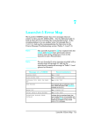
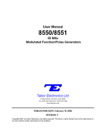
The NF gets worse for low source
resistances because the source's thermal
noise gets very small, while the amplifier's
input voltage noise stays relatively constant.
The NF gets worse for low frequencies and
low source resistances because the
amplifier's "1/f" noise is large relative to the
thermal noise of the source.
NOISE CONTOURS
The noise contours (shown below) plot the
noise figure as a function of source
impedance and frequency. Noise Figure
(NF) is defined as:
•
The NF gets worse for large source
impedances and high frequencies because
the signal is attenuated (hence the gain
reduced) by the shunting capacitance of the
input.
NF = 20 log (Output noise / (Gain X
Source Thermal Noise)
Under no circumstances will adding source
resistance reduce the amplifier's output
noise! While this does improve the NF, it
does so by making the source so noisy that
the amplifier is quiet in comparison.
A low noise figure means that the output
noise is dominated by the thermal
(Johnson) noise of the source. A high noise
figure indicates that the amplifier's output
noise is dominated by the amplifier's own
noise, which is much larger than the thermal
noise of the source.
10 8
10
1 dB
.5 dB
7
3 dB
SOURCE RESISTANCE IN OHMS AT 290K
.15 dB
10 6
10
5
10
4
.05 dB
.05 dB
.15 dB
.5 dB
1 dB
10 3
3 dB
6 dB
10
2
10 dB
15 dB
10
20 dB
25 dB
1
1
10
102
10 3
FREQUENCY IN Hz
19
10 4
10 5
10 6
CALIBRATION AND REPAIR
configuration (gain, filters and dynamic
reserve setting). The figure below shows
the dynamic reserve (and maximum input
signal without overload) for a SR560 set to
a gain of 1000, the high pass filter set to 1
kHz and the low pass filter set to 10 kHz (for
a bandpass from 1 kHz to 10 kHz). The
dynamic reserve characteristic is shown for
both "High Dynamic Reserve" and "Low
Noise" gain modes.
INPUT VOLTAGE NOISE
The amplifier's input voltage noise
approximates that of a 1000Ω resistor
(about 4 nV/√Hz). For source impedances
below 1000Ω, the output noise will be
dominated by the amplifier's input voltage
noise. A typical amplifier has an input
voltage noise vs. frequency as shown in the
figure below. Notice that the voltage noise
rises at lower frequencies (“1/f" noise).
There are several features to note. In the
bandpass region between 1 and 10 kHz the
dynamic reserve is 0 dB. The dynamic
reserve is 3 dB at the filter frequencies of 1
and 10 kHz. The dynamic reserve rises by
6 dB/oct (or 20 dB per decade) as the signal
moves away from the pole frequency, since
each RC filter attenuates the signal. If a
faster roll-off for interfering signals were
required, a 12 dB/octave HP or LP filter
could be used.
The HIGH DR characteristic offers 16 dB
more DR at low frequencies and 26 dB
more at high frequencies. The high
frequency DR is limited only by the
maximum 3 Vpp limit of the input stage.
The maximum DR in the low noise mode is
36 dB. Since there is no gain between the
HP and LP filters in the Low Noise gain
mode, the DR is the same at very high
frequencies and very low frequencies.
DYNAMIC RESERVE
The dynamic reserve of the amplifier is a
measure of how large a signal can be
present at the input to the amplifier without
causing an overload condition.
The input reference voltage noise for the
High DR gain mode is about 10 nV/√Hz,
compared to 4 nV/√Hz in the Low Noise
gain mode. The table (middle of next page)
summarizes the input referenced noise and
maximum dynamic reserve for all gains.
The definition of dynamic reserve is:
•
DR (dB) = 20 log (Vin(f) w/o
overload / Vin for full scale)
A full-scale output voltage is 10 Vpp.
Signals at the output (or at any stage) which
exceed 10 Vpp cause an overload. The
dynamic reserve is greater than 0 dB only
when the filters are used to remove
unwanted signals.
The dynamic reserve is a function of
frequency and depends on the amplifier
20
CALIBRATION AND REPAIR
Gain
Input Noise
(nV/√ Hz )
Maximum
DR (dB 0)
1
60
0
2
40
0
5
25
6
10, LN
10, HDR
13
25
6
14
20, LN
20, HDR
11
25
6
20
50, LN
50, HDR
10
25
14
28
100, LN
100, HDR
4
20
14
34
200, LN
200, HDR
4
18
20
40
500, LN
500, HDR
4
15
28
48
1000, LN
1000, HDR
4
15
34
54
Gain
21
Input Noise
(nV/√ Hz )
Maximum
DR (dB 0)
2000, LN
2000, HDR
4
10
40
52
5000, LN
5000, MDR
4
8
48
54
10000
4
54
20000
4
52
50000
4
54
CALIBRATION AND REPAIR
22
APPENDIX A
1 = 6 dB low pass,
2 = 12 dB low pass,
3 = 6 dB high pass,
4 = 12 dB highpass,
5 = bandpass
REMOTE PROGRAMMING
Introduction
The SR560 is equipped with a standard DB25 RS-232C connector on the rear panel for
remote control of all instrument functions.
The interface is configured as listen-only,
9600 baud DCE, 8-bit, no parity, 2 stop bits,
and is optically isolated to prevent any noise
or grounding problems.
Up to four SR560 amplifiers can be
connected in parallel to the same RS-232
interface. Units sharing the same interface
must have a unique address as set on dip
switch SW601, accessible through the
bottom cover of the unit. To set an
instrument to one of the four available
addresses, adjust positions one and two of
dip switch SW601 as follows:
SW601
Pos. 2
OFF
OFF
ON
ON
Pos.1
OFF
ON
OFF
ON
Address
of unit
UNIT 0
UNIT 1
UNIT 2
UNIT 3
Commands
The following commands are obeyed by all
SR560’s that are addressed to listen. The
LALL, LISN, and UNLS commands are
always obeyed and control the address
status of the SR560. Commands must end
with a carriage return and line feed <CR>
<LF>.
GAIN i
Sets the gain.
i = 0 – 14 = 1, 2, 5, … 50 k gain
HFRQi
Sets highpass filter frequency.
I = 0 – 11 sets frequency = 0.03
Hz to 10 kHz
INVT i
Sets the signal invert sense.
i = 0 = non-inverted,
1 = inverted
LALL
Listen all. Makes all attached
SR560’s listeners.
LISN i
Listen command. Makes
SR560 with address i (0,1,2,3)
a listener.
LFRQ i
Sets lowpass filter frequency.
i = 0 – 15 sets frequency
= 0.03 Hz to 1 MHz
ROLD
Resets overload for ½ second.
SRCE i
Sets the input source.
i = 0 = A, 1 = A-B, 2 = B
UCAL i
Sets the vernier gain status.
i = 0 = cal’d gain,
1 = vernier gain
UCGN i
Sets the vernier gain to i %.
i = 0 to 100
BLINK i
Operates amplifier blanking.
i = 0 = not blanked, 1 = blanked
UNLS
Unlisten. Unaddresses all
attached SR560’s.
CPLGi
Sets input coupling.
I = 0 = ground, 1 = DC, 2 = AC
*RST
Reset. Recalls default settings.
DYNR i
Sets dynamic reserve.
i = 0 = low noise, 1 = high DR,
2 = calibration gains (defaults)
FLTM i
Sets filter mode.
i = 0 = bypass,
A-1
APPENDIX A
A-2
APPENDIX B
for carbon, R is the resistance, I the current,
the bandwidth of our detector, and f is the
frequency to which the detector is tuned.
For a carbon resistor carrying 10 mA with
R = 1 k, ∆f = f = 1 Hz, we have:
NOISE SOURCES AND CURES
Noise, random and uncorrelated fluctuations
of electronic signals, finds its way into
experiments in a variety of ways. Good
laboratory practice can reduce noise
sources to a manageable level, and the
lock-in technique can be used to recover
signals, which may still be buried in noise.
Vnoise= 3µVrms
Others
Intrinsic Noise Sources
Other noise sources include flicker noise
found in vacuum tubes, and generation and
recombination noise found in
semiconductors.
Johnson Noise
Arising from fluctuations of electron density
in a resistor at finite temperature, these
fluctuations give rise to a mean square
noise voltage,
_
V2 = ∫4kT Re [Z(f)]df = 4 kTR∆f
All of these noise sources are incoherent.
Thus, the total noise is the square root of
the sum of the squares of all the incoherent
noise sources.
where k = Boltzmann’s constant,
1.38 x 10⁻²³J/°K; T is the absolute
temperature in Kelvin; the real part of the
impedance, Re[z(f)] is the resistance R; and
we are looking at the noise source with a
detector, or AC voltmeter, with a bandwidth
of ∆f in Hz. For a 1 MΩ resistor:
_
(V2) 1/2 = 0.13µV/√Hz
In addition to the “intrinsic” noise sources
listed above there are a variety of “nonessential” noise sources, (i.e. those noise
sources which can be minimized with good
laboratory practice). It is worthwhile to look
at what might be a typical noise spectrum
encountered in the laboratory environment:
Non-Essential Noise Sources
To obtain the rms noise voltage that you
would see across this 1MΩ resistor, we
multiply 0.3 µV/√Hz by the square root of
the detector bandwidth. If, for example, we
were looking at all frequencies between DC
and 1 MHz, we would expect to see a rms
Johnson noise of:
_
(V2) 1/2 = 0.13µV/√Hz * (106 Hz) 1/2 = 130 µV
‘1/f Noise’
Arising from resistance fluctuations in a
current carrying resistor, the mean squared
noise voltage due to ‘1/f ‘noise is given by,
_
V2 = AR2I2 ∆f/f
Noise Spectrum
Some of the non-essential noise sources
appear in this spectrum as spikes on the
intrinsic background. There are several
where A is a dimensionless constant, 10-11
B-1
APPENDIX B
ways which these noise sources work their
way into an experiment.
3) Install capacitive shielding by placing
both the experiment and the detector in
a metal box.
Capacitive Coupling
A voltage on a nearby piece of apparatus
(or operator) can couple to a detector via a
stray capacitance. Although Cstray may be
very small, the coupled in noise may still be
larger than a weak experimental signal.
Inductive Noise Coupling
Inductive Coupling
Capacitive Noise Coupling
Here noise couples to the experiment via a
magnetic field:
To estimate the noise current through Cstray
into the detector we have
A changing current in a nearby circuit gives
rise to a changing magnetic field which
induces an emf in the loop connecting the
detector to the experiment, (emf = dØB/dt).
This is like a transformer, with the
experiment-detector loop as the secondary
winding.
I = Cstray dV = jwcstray Vnoise
dt
Where a reasonable approximation to Cstray
can be made by treating it as parallel plate
capacitor. Here, w is the radian frequency of
the noise source (perhaps 2 ∗ π ∗ 60 Hz),
Vnoise is the noise voltage source amplitude
(perhaps 120 VAC). For an area of A =
(0.01 m)2 and a distance of d = 0.1 m, the
‘capacitor’ will have a value of 0.009 pF and
the resulting noise current will be 400 pA.
This meager current is about 4000 times
larger than the most sensitive current scale
that is available on the SR510 lock-in.
Cures for inductively coupled noise include:
1) Remove or turn off the interfering noise
source (difficult to do if the noise is a
broadcast station).
2) Reduce the area of the pick-up loop by
using twisted pairs or coaxial cables, or
even twisting the 2 coaxial cables used
in differential hookups.
Cures for capacitive coupling of noise
signals include:
1) Remove or turn off the interfering noise
source.
3) Use magnetic shielding to prevent the
magnetic field from inducing an emf (at
high frequencies a simple metal
enclosure is adequate).
2) Measure voltages with low impedance
sources and measure currents with high
impedance sources to reduce the effect
of istray.
4) Measure currents, not voltages, from
high impedance experiments.
B-2
APPENDIX B
The capacitance of a coaxial cable is a
function of its geometry so mechanical
vibrations will cause the cable capacitance
to vary with time.
Resistive Coupling (or ‘Ground
Loops’)
Currents through common connections can
give rise to noise voltages.
Since C = Q/V, we have:
C dV + V dC = dQ = i
dt
dt
dt
So mechanical vibrations will cause a dC/dt
which in turn gives rise to a current i, which
will affect the detector. Ways to eliminate
microphonic signals include:
1) Eliminate mechanical vibrations.
Resistive Coupling
2) Tie down experimental cables so they
will not sway to and fro.
Here, the detector is measuring the voltage
across the experiment, plus the voltage due
to the noise current passing through the
finite resistance of the ground bus. This
problem arises because we have used two
different grounding points, which are not at
exactly the same potential. Some cures for
ground loop problems include:
3) Use a low noise cable that is designed
to reduce microphonic effects.
Thermocouple Effect
The emf created by dissimilar metal
junctions can give rise to many microvolts of
DC potential, and can be a source of AC
noise if the temperature of the junction is
not held constant. This effect is large on the
scale of many low level measurements.
1) Ground everything to the same physical
point.
2) Use a heavier ground bus to reduce the
potential drop along the ground bus.
3) Remove sources of large currents from
ground wires used for small signals.
Microphonics
Microphonics provides a path for
mechanical noise to appear as electrical
noise in a circuit or experiment. Consider
the simple circuit below:
B-3
APPENDIX B
B-4
SR560 COMPONENT PARTS LIST
Front Panel Parts List
REF.
D1
D2
D3
D4
D5
D6
D7
D8
D9
D 10
D 11
D 12
D 13
D 14
D 15
D 16
D 17
D 18
D 19
D 20
D 21
D 22
D 23
D 24
D 25
D 26
D 27
D 28
D 29
D 30
D 31
D 32
D 33
D 34
D 35
D 36
D 37
D 38
D 39
D 40
D 41
D 42
D 43
D 44
D 45
D 46
D 47
SRS part#
3-00884-306
3-00012-306
3-00012-306
3-00012-306
3-00012-306
3-00012-306
3-00012-306
3-00012-306
3-00012-306
3-00885-306
3-00012-306
3-00012-306
3-00012-306
3-00012-306
3-00012-306
3-00012-306
3-00012-306
3-00012-306
3-00012-306
3-00012-306
3-00012-306
3-00012-306
3-00012-306
3-00012-306
3-00012-306
3-00012-306
3-00012-306
3-00012-306
3-00012-306
3-00012-306
3-00012-306
3-00012-306
3-00012-306
3-00012-306
3-00012-306
3-00012-306
3-00012-306
3-00885-306
3-00885-306
3-00012-306
3-00012-306
3-00012-306
3-00004-301
3-00004-301
3-00004-301
3-00004-301
3-00377-305
VALUE
RED
GREEN
GREEN
GREEN
GREEN
GREEN
GREEN
GREEN
GREEN
YELLOW
GREEN
GREEN
GREEN
GREEN
GREEN
GREEN
GREEN
GREEN
GREEN
GREEN
GREEN
GREEN
GREEN
GREEN
GREEN
GREEN
GREEN
GREEN
GREEN
GREEN
GREEN
GREEN
GREEN
GREEN
GREEN
GREEN
GREEN
YELLOW
YELLOW
GREEN
GREEN
GREEN
1N4148
1N4148
1N4148
1N4148
GL9ED2
DESCRIPTION
LED, Rectangular
LED, Rectangular
LED, Rectangular
LED, Rectangular
LED, Rectangular
LED, Rectangular
LED, Rectangular
LED, Rectangular
LED, Rectangular
LED, Rectangular
LED, Rectangular
LED, Rectangular
LED, Rectangular
LED, Rectangular
LED, Rectangular
LED, Rectangular
LED, Rectangular
LED, Rectangular
LED, Rectangular
LED, Rectangular
LED, Rectangular
LED, Rectangular
LED, Rectangular
LED, Rectangular
LED, Rectangular
LED, Rectangular
LED, Rectangular
LED, Rectangular
LED, Rectangular
LED, Rectangular
LED, Rectangular
LED, Rectangular
LED, Rectangular
LED, Rectangular
LED, Rectangular
LED, Rectangular
LED, Rectangular
LED, Rectangular
LED, Rectangular
LED, Rectangular
LED, Rectangular
LED, Rectangular
Diode
Diode
Diode
Diode
LED, Rectangular, Bicolor
C-1
SR560 COMPONENT PARTS LIST
D 48
J1
N1
N2
N3
N4
N5
P1
Q1
Q2
R1
R2
R3
R4
SW1
SW2
SW3
SW4
SW5
SW6
SW7
SW8
SW9
SW10
SW11
SW12
U1
U2
U3
U4
U5
Z0
3-00004-301
1-00035-130
4-00651-425
4-00651-425
4-00651-425
4-00336-425
4-00298-425
4-00611-452
3-00022-325
3-00021-325
4-00057-401
4-00059-401
4-00041-401
4-00081-401
2-00031-201
2-00031-201
2-00031-201
2-00031-201
2-00031-201
2-00031-201
2-00031-201
2-00031-201
2-00031-201
2-00031-201
2-00031-201
2-00031-201
3-00303-340
3-00303-340
3-00303-340
3-00303-340
3-00303-340
7-00223-701
1N4148
20 PIN DIL
270X9
270X9
270X9
270X5
470X5
100K
2N3906
2N3904
220
22K
150
470
D6-01-05
D6-01-05
D6-01-05
D6-01-05
D6-01-05
D6-01-05
D6-01-05
D6-01-05
D6-01-05
D6-01-05
D6-01-05
D6-01-05
74HC164
74HC164
74HC164
74HC164
74HC164
SR560-XX
Diode
Connector, Male
Resistor Network SIP 1/4W 2% (Common)
Resistor Network SIP 1/4W 2% (Common)
Resistor Network SIP 1/4W 2% (Common)
Resistor Network SIP 1/4W 2% (Common)
Resistor Network SIP 1/4W 2% (Common)
Pot, Multi Turn Trim, Mini
Transistor, TO-92 Package
Transistor, TO-92 Package
Resistor, Carbon Film, 1/4W, 5%
Resistor, Carbon Film, 1/4W, 5%
Resistor, Carbon Film, 1/4W, 5%
Resistor, Carbon Film, 1/4W, 5%
Switch, Momentary Push Button
Switch, Momentary Push Button
Switch, Momentary Push Button
Switch, Momentary Push Button
Switch, Momentary Push Button
Switch, Momentary Push Button
Switch, Momentary Push Button
Switch, Momentary Push Button
Switch, Momentary Push Button
Switch, Momentary Push Button
Switch, Momentary Push Button
Switch, Momentary Push Button
Integrated Circuit (Thru-hole Pkg)
Integrated Circuit (Thru-hole Pkg)
Integrated Circuit (Thru-hole Pkg)
Integrated Circuit (Thru-hole Pkg)
Integrated Circuit (Thru-hole Pkg)
Printed Circuit Board
Main Board Parts List
REF.
BT1
BT2
BT3
C 101
C 102
C 103
C 104
C 106
C 107
C 108
C 109
C 110
C 111
SRS part#
6-00050-612
6-00050-612
6-00050-612
5-00098-517
5-00098-517
5-00098-517
5-00098-517
5-00069-513
5-00069-513
5-00013-501
5-00013-501
5-00159-501
5-00019-501
VALUE
GB1219-36
GB1219-36
GB1219-36
10U
10U
10U
10U
.1U
.1U
33P
33P
6.8P
68P
DESCRIPTION
Battery
Battery
Battery
Capacitor, Tantalum, 35V, 20%, Rad
Capacitor, Tantalum, 35V, 20%, Rad
Capacitor, Tantalum, 35V, 20%, Rad
Capacitor, Tantalum, 35V, 20%, Rad
Capacitor, Mylar/Poly, 50V, 5%, Rad
Capacitor, Mylar/Poly, 50V, 5%, Rad
Capacitor, Ceramic Disc, 50V, 10%, SL
Capacitor, Ceramic Disc, 50V, 10%, SL
Capacitor, Ceramic Disc, 50V, 10%, SL
Capacitor, Ceramic Disc, 50V, 10%, SL
C-2
SR560 COMPONENT PARTS LIST
C 112
C 113
C 114
C 115
C 116
C 201
C 202
C 203
C 204
C 205
C 206
C 208
C 209
C 210
C 211
C 212
C 213
C 214
C 215
C 216
C 217
C 218
C 219
C 220
C 221
C 222
C 223
C 224
C 225
C 226
C 227
C 228
C 230
C 301
C 302
C 303
C 304
C 306
C 307
C 308
C 309
C 310
C 311
C 312
C 313
C 314
C 315
C 316
C 317
C 318
5-00023-529
5-00100-517
5-00100-517
5-00100-517
5-00005-501
5-00019-501
5-00100-517
5-00100-517
5-00100-517
5-00100-517
5-00100-517
5-00010-501
5-00061-513
5-00063-513
5-00065-513
5-00067-513
5-00023-529
5-00194-542
5-00194-542
5-00193-542
5-00193-542
5-00213-546
5-00213-546
5-00033-520
5-00033-520
5-00031-520
5-00031-520
5-00232-520
5-00232-520
5-00192-542
5-00192-542
5-00008-501
5-00100-517
5-00017-501
5-00100-517
5-00100-517
5-00100-517
5-00008-501
5-00010-501
5-00061-513
5-00063-513
5-00065-513
5-00067-513
5-00023-529
5-00194-542
5-00194-542
5-00193-542
5-00193-542
5-00213-546
5-00213-546
.1U
2.2U
2.2U
2.2U
150P
68P
2.2U
2.2U
2.2U
2.2U
2.2U
270P
.001U
.0033U
.01U
.033U
.1U
.47U MIN
.47U MIN
2.2U MIN
2.2U MIN
4.7U
4.7U
47U
47U
220U
220U
470U
470U
22U MIN
22U MIN
22P
2.2U
47P
2.2U
2.2U
2.2U
22P
270P
.001U
.0033U
.01U
.033U
.1U
.47U MIN
.47U MIN
2.2U MIN
2.2U MIN
4.7U
4.7U
Cap, Monolythic Ceramic, 50V, 20%, Z5U
Capacitor, Tantalum, 35V, 20%, Rad
Capacitor, Tantalum, 35V, 20%, Rad
Capacitor, Tantalum, 35V, 20%, Rad
Capacitor, Ceramic Disc, 50V, 10%, SL
Capacitor, Ceramic Disc, 50V, 10%, SL
Capacitor, Tantalum, 35V, 20%, Rad
Capacitor, Tantalum, 35V, 20%, Rad
Capacitor, Tantalum, 35V, 20%, Rad
Capacitor, Tantalum, 35V, 20%, Rad
Capacitor, Tantalum, 35V, 20%, Rad
Capacitor, Ceramic Disc, 50V, 10%, SL
Capacitor, Mylar/Poly, 50V, 5%, Rad
Capacitor, Mylar/Poly, 50V, 5%, Rad
Capacitor, Mylar/Poly, 50V, 5%, Rad
Capacitor, Mylar/Poly, 50V, 5%, Rad
Cap, Monolythic Ceramic, 50V, 20%, Z5U
Cap, Mini Electrolytic, 50V, 20% Radial
Cap, Mini Electrolytic, 50V, 20% Radial
Cap, Mini Electrolytic, 50V, 20% Radial
Cap, Mini Electrolytic, 50V, 20% Radial
Cap, Mini Electro, 100V, 20%, Rad
Cap, Mini Electro, 100V, 20%, Rad
Capacitor, Electrolytic, 16V, 20%, Rad
Capacitor, Electrolytic, 16V, 20%, Rad
Capacitor, Electrolytic, 16V, 20%, Rad
Capacitor, Electrolytic, 16V, 20%, Rad
Capacitor, Electrolytic, 16V, 20%, Rad
Capacitor, Electrolytic, 16V, 20%, Rad
Cap, Mini Electrolytic, 50V, 20% Radial
Cap, Mini Electrolytic, 50V, 20% Radial
Capacitor, Ceramic Disc, 50V, 10%, SL
Capacitor, Tantalum, 35V, 20%, Rad
Capacitor, Ceramic Disc, 50V, 10%, SL
Capacitor, Tantalum, 35V, 20%, Rad
Capacitor, Tantalum, 35V, 20%, Rad
Capacitor, Tantalum, 35V, 20%, Rad
Capacitor, Ceramic Disc, 50V, 10%, SL
Capacitor, Ceramic Disc, 50V, 10%, SL
Capacitor, Mylar/Poly, 50V, 5%, Rad
Capacitor, Mylar/Poly, 50V, 5%, Rad
Capacitor, Mylar/Poly, 50V, 5%, Rad
Capacitor, Mylar/Poly, 50V, 5%, Rad
Cap, Monolythic Ceramic, 50V, 20%, Z5U
Cap, Mini Electrolytic, 50V, 20% Radial
Cap, Mini Electrolytic, 50V, 20% Radial
Cap, Mini Electrolytic, 50V, 20% Radial
Cap, Mini Electrolytic, 50V, 20% Radial
Cap, Mini Electro, 100V, 20%, Rad
Cap, Mini Electro, 100V, 20%, Rad
C-3
SR560 COMPONENT PARTS LIST
C 319
C 320
C 321
C 322
C 323
C 324
C 325
C 326
C 327
C 328
C 330
C 401
C 402
C 403
C 404
C 405
C 406
C 407
C 408
C 409
C 410
C 411
C 412
C 413
C 414
C 415
C 416
C 417
C 418
C 502
C 503
C 703
C 704
C 705
C 706
C 707
C 708
C 709
C 710
C 711
C 712
C 713
C 714
C 715
C 716
C 717
C 718
C 801
C 802
C 803
5-00033-520
5-00033-520
5-00031-520
5-00031-520
5-00232-520
5-00232-520
5-00023-529
5-00023-529
5-00192-542
5-00192-542
5-00100-517
5-00017-501
5-00100-517
5-00100-517
5-00100-517
5-00100-517
5-00021-501
5-00107-530
5-00100-517
5-00100-517
5-00100-517
5-00002-501
5-00100-517
5-00061-513
5-00061-513
5-00100-517
5-00023-529
5-00023-529
5-00023-529
5-00104-530
5-00233-532
5-00023-529
5-00023-529
5-00023-529
5-00234-551
5-00234-551
5-00100-517
5-00227-526
5-00227-526
5-00100-517
5-00023-529
5-00100-517
5-00100-517
5-00100-517
5-00023-529
5-00023-529
5-00262-548
5-00225-548
5-00225-548
5-00225-548
47U
47U
220U
220U
470U
470U
.1U
.1U
22U MIN
22U MIN
2.2U
47P
2.2U
2.2U
2.2U
2.2U
82P
1.8-6P
2.2U
2.2U
2.2U
100P
2.2U
.001U
.001U
2.2U
.1U
.1U
.1U
3.5-20P
22P
.1U
.1U
.1U
1000U
1000U
2.2U
100U
100U
2.2U
.1U
2.2U
2.2U
2.2U
.1U
.1U
.01U AXIAL
.1U AXIAL
.1U AXIAL
.1U AXIAL
Capacitor, Electrolytic, 16V, 20%, Rad
Capacitor, Electrolytic, 16V, 20%, Rad
Capacitor, Electrolytic, 16V, 20%, Rad
Capacitor, Electrolytic, 16V, 20%, Rad
Capacitor, Electrolytic, 16V, 20%, Rad
Capacitor, Electrolytic, 16V, 20%, Rad
Cap, Monolythic Ceramic, 50V, 20%, Z5U
Cap, Monolythic Ceramic, 50V, 20%, Z5U
Cap, Mini Electrolytic, 50V, 20% Radial
Cap, Mini Electrolytic, 50V, 20% Radial
Capacitor, Tantalum, 35V, 20%, Rad
Capacitor, Ceramic Disc, 50V, 10%, SL
Capacitor, Tantalum, 35V, 20%, Rad
Capacitor, Tantalum, 35V, 20%, Rad
Capacitor, Tantalum, 35V, 20%, Rad
Capacitor, Tantalum, 35V, 20%, Rad
Capacitor, Ceramic Disc, 50V, 10%, SL
Capacitor, Variable, Misc.
Capacitor, Tantalum, 35V, 20%, Rad
Capacitor, Tantalum, 35V, 20%, Rad
Capacitor, Tantalum, 35V, 20%, Rad
Capacitor, Ceramic Disc, 50V, 10%, SL
Capacitor, Tantalum, 35V, 20%, Rad
Capacitor, Mylar/Poly, 50V, 5%, Rad
Capacitor, Mylar/Poly, 50V, 5%, Rad
Capacitor, Tantalum, 35V, 20%, Rad
Cap, Monolythic Ceramic, 50V, 20%, Z5U
Cap, Monolythic Ceramic, 50V, 20%, Z5U
Cap, Monolythic Ceramic, 50V, 20%, Z5U
Capacitor, Variable, Misc.
Capacitor, Ceramic Disc, 50V, 10% NPO
Cap, Monolythic Ceramic, 50V, 20%, Z5U
Cap, Monolythic Ceramic, 50V, 20%, Z5U
Cap, Monolythic Ceramic, 50V, 20%, Z5U
Capacitor, Electrolytic,35V,20%, Ax
Capacitor, Electrolytic,35V,20%, Ax
Capacitor, Tantalum, 35V, 20%, Rad
Capacitor, Electrolytic, 35V, 20%, Rad
Capacitor, Electrolytic, 35V, 20%, Rad
Capacitor, Tantalum, 35V, 20%, Rad
Cap, Monolythic Ceramic, 50V, 20%, Z5U
Capacitor, Tantalum, 35V, 20%, Rad
Capacitor, Tantalum, 35V, 20%, Rad
Capacitor, Tantalum, 35V, 20%, Rad
Cap, Monolythic Ceramic, 50V, 20%, Z5U
Cap, Monolythic Ceramic, 50V, 20%, Z5U
Capacitor, Ceramic, 50V,+80/-20% Z5U AX
Capacitor, Ceramic, 50V,+80/-20% Z5U AX
Capacitor, Ceramic, 50V,+80/-20% Z5U AX
Capacitor, Ceramic, 50V,+80/-20% Z5U AX
C-4
SR560 COMPONENT PARTS LIST
C 804
C 805
C 806
C 807
C 808
C 809
C 810
C 811
C 812
C 813
C 814
C 815
C 816
C 817
C 818
C 819
C 820
C 821
C 822
C 823
C 824
C 825
C 826
C 827
C 828
C 829
C 830
C 831
C 832
D 101
D 201
D 202
D 301
D 302
D 401
D 402
D 403
D 404
D 405
D 406
D 407
D 408
D 501
D 502
D 503
D 505
D 701
D 702
D 703
D 704
5-00225-548
5-00225-548
5-00225-548
5-00225-548
5-00023-529
5-00225-548
5-00023-529
5-00225-548
5-00225-548
5-00225-548
5-00225-548
5-00225-548
5-00225-548
5-00225-548
5-00225-548
5-00225-548
5-00225-548
5-00023-529
5-00100-517
5-00023-529
5-00023-529
5-00100-517
5-00100-517
5-00100-517
5-00100-517
5-00100-517
5-00023-529
5-00023-529
5-00023-529
3-00368-301
3-00368-301
3-00368-301
3-00368-301
3-00368-301
3-00004-301
3-00004-301
3-00004-301
3-00004-301
3-00004-301
3-00004-301
3-00004-301
3-00004-301
3-00004-301
3-00004-301
3-00004-301
3-00004-301
3-00226-301
3-00004-301
3-00226-301
3-00009-303
.1U AXIAL
.1U AXIAL
.1U AXIAL
.1U AXIAL
.1U
.1U AXIAL
.1U
.1U AXIAL
.1U AXIAL
.1U AXIAL
.1U AXIAL
.1U AXIAL
.1U AXIAL
.1U AXIAL
.1U AXIAL
.1U AXIAL
.1U AXIAL
.1U
2.2U
.1U
.1U
2.2U
2.2U
2.2U
2.2U
2.2U
.1U
.1U
.1U
1N753A
1N753A
1N753A
1N753A
1N753A
1N4148
1N4148
1N4148
1N4148
1N4148
1N4148
1N4148
1N4148
1N4148
1N4148
1N4148
1N4148
1N5822
1N4148
1N5822
YELLOW
Capacitor, Ceramic, 50V,+80/-20% Z5U AX
Capacitor, Ceramic, 50V,+80/-20% Z5U AX
Capacitor, Ceramic, 50V,+80/-20% Z5U AX
Capacitor, Ceramic, 50V,+80/-20% Z5U AX
Cap, Monolythic Ceramic, 50V, 20%, Z5U
Capacitor, Ceramic, 50V,+80/-20% Z5U AX
Cap, Monolythic Ceramic, 50V, 20%, Z5U
Capacitor, Ceramic, 50V,+80/-20% Z5U AX
Capacitor, Ceramic, 50V,+80/-20% Z5U AX
Capacitor, Ceramic, 50V,+80/-20% Z5U AX
Capacitor, Ceramic, 50V,+80/-20% Z5U AX
Capacitor, Ceramic, 50V,+80/-20% Z5U AX
Capacitor, Ceramic, 50V,+80/-20% Z5U AX
Capacitor, Ceramic, 50V,+80/-20% Z5U AX
Capacitor, Ceramic, 50V,+80/-20% Z5U AX
Capacitor, Ceramic, 50V,+80/-20% Z5U AX
Capacitor, Ceramic, 50V,+80/-20% Z5U AX
Cap, Monolythic Ceramic, 50V, 20%, Z5U
Capacitor, Tantalum, 35V, 20%, Rad
Cap, Monolythic Ceramic, 50V, 20%, Z5U
Cap, Monolythic Ceramic, 50V, 20%, Z5U
Capacitor, Tantalum, 35V, 20%, Rad
Capacitor, Tantalum, 35V, 20%, Rad
Capacitor, Tantalum, 35V, 20%, Rad
Capacitor, Tantalum, 35V, 20%, Rad
Capacitor, Tantalum, 35V, 20%, Rad
Cap, Monolythic Ceramic, 50V, 20%, Z5U
Cap, Monolythic Ceramic, 50V, 20%, Z5U
Cap, Monolythic Ceramic, 50V, 20%, Z5U
Diode
Diode
Diode
Diode
Diode
Diode
Diode
Diode
Diode
Diode
Diode
Diode
Diode
Diode
Diode
Diode
Diode
Diode
Diode
Diode
LED, T1 Package
C-5
SR560 COMPONENT PARTS LIST
D 705
D 706
D 707
D 708
D 709
D 710A
D 710B
D 711
D 801
D 802
D 803
J 101
J 102
J 404
J 405
J 601
J 805
JP801
K 101
K 102
K 103
K 104
K 105
K 201
K 301
N 701
N 702
P 101
P 102
P 103
P 104
P 701
P 702
Q 102
Q 103
Q 104
Q 105
Q 106
Q 107
Q 108
Q 109
Q 110
Q 111
Q 201
Q 202
Q 301
Q 302
Q 501
Q 701
Q 702
3-00011-303
3-00062-340
3-00226-301
3-00226-301
3-00306-340
3-00391-301
3-00391-301
3-00198-301
3-00226-301
3-00004-301
3-00004-301
1-00073-120
1-00073-120
1-00073-120
1-00073-120
1-00035-130
1-00073-120
1-00016-160
3-00308-335
3-00308-335
3-00308-335
3-00308-335
3-00308-335
3-00308-335
3-00308-335
4-00497-421
4-00501-425
4-00353-441
4-00487-441
4-00617-441
4-00617-441
4-00011-441
4-00011-441
3-00022-325
3-00022-325
3-00022-325
3-00022-325
3-00022-325
3-00022-325
3-00022-325
3-00022-325
3-00022-325
3-00022-325
3-00022-325
3-00022-325
3-00022-325
3-00022-325
3-00021-325
3-00310-329
3-00887-325
RED
KBP201G/BR-81D
1N5822
1N5822
LM385BZ-2.5
MBR360
MBR360
1N5231B
1N5822
1N4148
1N4148
INSL
INSL
INSL
INSL
20 PIN DIL
INSL
RS232 25 PIN D
DS2E-ML2-DC5V
DS2E-ML2-DC5V
DS2E-ML2-DC5V
DS2E-ML2-DC5V
DS2E-ML2-DC5V
DS2E-ML2-DC5V
DS2E-ML2-DC5V
1.5KX4
1.0MX5
100
20
100K
100K
10K
10K
2N3906
2N3906
2N3906
2N3906
2N3906
2N3906
2N3906
2N3906
2N3906
2N3906
2N3906
2N3906
2N3906
2N3906
2N3904
MTP25N05
MPS2907A
LED, T1 Package
Integrated Circuit (Thru-hole Pkg)
Diode
Diode
Integrated Circuit (Thru-hole Pkg)
Diode
Diode
Diode
Diode
Diode
Diode
Connector, BNC
Connector, BNC
Connector, BNC
Connector, BNC
Connector, Male
Connector, BNC
Connector, D-Sub, Right Angle PC, Female
Relay
Relay
Relay
Relay
Relay
Relay
Relay
Res. Network, SIP, 1/4W,2% (Isolated)
Resistor Network SIP 1/4W 2% (Common)
Pot, Multi-Turn Trim, 3/8" Square Top Ad
Pot, Multi-Turn Trim, 3/8" Square Top Ad
Pot, Multi-Turn Trim, 3/8" Square Top Ad
Pot, Multi-Turn Trim, 3/8" Square Top Ad
Pot, Multi-Turn Trim, 3/8" Square Top Ad
Pot, Multi-Turn Trim, 3/8" Square Top Ad
Transistor, TO-92 Package
Transistor, TO-92 Package
Transistor, TO-92 Package
Transistor, TO-92 Package
Transistor, TO-92 Package
Transistor, TO-92 Package
Transistor, TO-92 Package
Transistor, TO-92 Package
Transistor, TO-92 Package
Transistor, TO-92 Package
Transistor, TO-92 Package
Transistor, TO-92 Package
Transistor, TO-92 Package
Transistor, TO-92 Package
Transistor, TO-92 Package
Voltage Reg., TO-220 (TAB) Package
Transistor, TO-92 Package
C-6
SR560 COMPONENT PARTS LIST
Q 703
Q 801
R2
R 101
R 102
R 103
R 104
R 105
R 106
R 108
R 109
R 110
R 111
R 112
R 113
R 114
R 115
R 116
R 117
R 118
R 119
R 120
R 121
R 122
R 123
R 124
R 125
R 126
R 127
R 128
R 129
R 130
R 131
R 132
R 133
R 134
R 135
R 136
R 137
R 201
R 202
R 203
R 204
R 205
R 206
R 207
R 208
R 209
R 210
R 211
3-00374-329
3-00376-329
4-00616-453
4-00306-407
4-00306-407
4-00030-401
4-00030-401
4-00030-401
4-00030-401
4-00169-407
4-00041-401
4-00141-407
4-00217-408
4-00030-401
4-00301-408
4-00301-408
4-00619-408
4-00193-407
4-00528-408
4-00217-408
4-00544-407
4-00142-407
4-00203-407
4-00021-401
4-00215-407
4-00141-407
4-00192-407
4-00034-401
4-00142-407
4-00619-408
4-00142-407
4-00031-401
4-00528-408
4-00030-401
4-00030-401
4-00102-401
4-00030-401
4-00142-407
4-00030-401
4-00516-407
4-00164-407
4-00516-407
4-00168-407
4-00516-407
4-00168-407
4-00600-407
4-00168-407
4-00600-407
4-00600-407
4-00600-407
MTP20P06
MTP5N05
49.9
100M
100M
10
10
10
10
249
150
100
1.000K
10
110
110
909
499
499
1.000K
165
100K
75.0K
1.0K
909
100
49.9K
10K
100K
909
100K
100
499
10
10
75K
10
100K
10
14.3K
20.0K
14.3K
22.6K
14.3K
22.6K
15.8K
22.6K
15.8K
15.8K
15.8K
Voltage Reg., TO-220 (TAB) Package
Voltage Reg., TO-220 (TAB) Package
Resistor, 2W, 1%
Resistor, Metal Film, 1/8W, 1%, 50PPM
Resistor, Metal Film, 1/8W, 1%, 50PPM
Resistor, Carbon Film, 1/4W, 5%
Resistor, Carbon Film, 1/4W, 5%
Resistor, Carbon Film, 1/4W, 5%
Resistor, Carbon Film, 1/4W, 5%
Resistor, Metal Film, 1/8W, 1%, 50PPM
Resistor, Carbon Film, 1/4W, 5%
Resistor, Metal Film, 1/8W, 1%, 50PPM
Resistor, Metal Film, 1/8W, 0.1%, 25ppm
Resistor, Carbon Film, 1/4W, 5%
Resistor, Metal Film, 1/8W, 0.1%, 25ppm
Resistor, Metal Film, 1/8W, 0.1%, 25ppm
Resistor, Metal Film, 1/8W, 0.1%, 25ppm
Resistor, Metal Film, 1/8W, 1%, 50PPM
Resistor, Metal Film, 1/8W, 0.1%, 25ppm
Resistor, Metal Film, 1/8W, 0.1%, 25ppm
Resistor, Metal Film, 1/8W, 1%, 50PPM
Resistor, Metal Film, 1/8W, 1%, 50PPM
Resistor, Metal Film, 1/8W, 1%, 50PPM
Resistor, Carbon Film, 1/4W, 5%
Resistor, Metal Film, 1/8W, 1%, 50PPM
Resistor, Metal Film, 1/8W, 1%, 50PPM
Resistor, Metal Film, 1/8W, 1%, 50PPM
Resistor, Carbon Film, 1/4W, 5%
Resistor, Metal Film, 1/8W, 1%, 50PPM
Resistor, Metal Film, 1/8W, 0.1%, 25ppm
Resistor, Metal Film, 1/8W, 1%, 50PPM
Resistor, Carbon Film, 1/4W, 5%
Resistor, Metal Film, 1/8W, 0.1%, 25ppm
Resistor, Carbon Film, 1/4W, 5%
Resistor, Carbon Film, 1/4W, 5%
Resistor, Carbon Film, 1/4W, 5%
Resistor, Carbon Film, 1/4W, 5%
Resistor, Metal Film, 1/8W, 1%, 50PPM
Resistor, Carbon Film, 1/4W, 5%
Resistor, Metal Film, 1/8W, 1%, 50PPM
Resistor, Metal Film, 1/8W, 1%, 50PPM
Resistor, Metal Film, 1/8W, 1%, 50PPM
Resistor, Metal Film, 1/8W, 1%, 50PPM
Resistor, Metal Film, 1/8W, 1%, 50PPM
Resistor, Metal Film, 1/8W, 1%, 50PPM
Resistor, Metal Film, 1/8W, 1%, 50PPM
Resistor, Metal Film, 1/8W, 1%, 50PPM
Resistor, Metal Film, 1/8W, 1%, 50PPM
Resistor, Metal Film, 1/8W, 1%, 50PPM
Resistor, Metal Film, 1/8W, 1%, 50PPM
C-7
SR560 COMPONENT PARTS LIST
R 212
R 213
R 214
R 215
R 216
R 217
R 218
R 219
R 220
R 221
R 222
R 223
R 224
R 225
R 226
R 227
R 228
R 229
R 301
R 302
R 303
R 304
R 305
R 306
R 307
R 308
R 309
R 310
R 311
R 312
R 313
R 314
R 315
R 316
R 317
R 318
R 319
R 320
R 321
R 322
R 323
R 324
R 325
R 326
R 327
R 328
R 329
R 330
R 401
R 402
4-00600-407
4-00600-407
4-00030-401
4-00165-407
4-00030-401
4-00325-407
4-00030-401
4-00030-401
4-00296-407
4-00165-407
4-00165-407
4-00140-407
4-00188-407
4-00158-407
4-00048-401
4-00048-401
4-00031-401
4-00305-401
4-00516-407
4-00164-407
4-00516-407
4-00168-407
4-00516-407
4-00168-407
4-00600-407
4-00168-407
4-00600-407
4-00600-407
4-00600-407
4-00030-401
4-00165-407
4-00030-401
4-00325-407
4-00030-401
4-00030-401
4-00296-407
4-00165-407
4-00165-407
4-00600-407
4-00600-407
4-00600-407
4-00705-407
4-00158-407
4-00048-401
4-00048-401
4-00030-401
4-00031-401
4-00065-401
4-00030-401
4-00030-401
15.8K
15.8K
10
200
10
845
10
10
604
200
200
10.2K
4.99K
2.00K
2.2K
2.2K
100
4.3K
14.3K
20.0K
14.3K
22.6K
14.3K
22.6K
15.8K
22.6K
15.8K
15.8K
15.8K
10
200
10
845
10
10
604
200
200
15.8K
15.8K
15.8K
5.62K
2.00K
2.2K
2.2K
10
100
3.3K
10
10
Resistor, Metal Film, 1/8W, 1%, 50PPM
Resistor, Metal Film, 1/8W, 1%, 50PPM
Resistor, Carbon Film, 1/4W, 5%
Resistor, Metal Film, 1/8W, 1%, 50PPM
Resistor, Carbon Film, 1/4W, 5%
Resistor, Metal Film, 1/8W, 1%, 50PPM
Resistor, Carbon Film, 1/4W, 5%
Resistor, Carbon Film, 1/4W, 5%
Resistor, Metal Film, 1/8W, 1%, 50PPM
Resistor, Metal Film, 1/8W, 1%, 50PPM
Resistor, Metal Film, 1/8W, 1%, 50PPM
Resistor, Metal Film, 1/8W, 1%, 50PPM
Resistor, Metal Film, 1/8W, 1%, 50PPM
Resistor, Metal Film, 1/8W, 1%, 50PPM
Resistor, Carbon Film, 1/4W, 5%
Resistor, Carbon Film, 1/4W, 5%
Resistor, Carbon Film, 1/4W, 5%
Resistor, Carbon Film, 1/4W, 5%
Resistor, Metal Film, 1/8W, 1%, 50PPM
Resistor, Metal Film, 1/8W, 1%, 50PPM
Resistor, Metal Film, 1/8W, 1%, 50PPM
Resistor, Metal Film, 1/8W, 1%, 50PPM
Resistor, Metal Film, 1/8W, 1%, 50PPM
Resistor, Metal Film, 1/8W, 1%, 50PPM
Resistor, Metal Film, 1/8W, 1%, 50PPM
Resistor, Metal Film, 1/8W, 1%, 50PPM
Resistor, Metal Film, 1/8W, 1%, 50PPM
Resistor, Metal Film, 1/8W, 1%, 50PPM
Resistor, Metal Film, 1/8W, 1%, 50PPM
Resistor, Carbon Film, 1/4W, 5%
Resistor, Metal Film, 1/8W, 1%, 50PPM
Resistor, Carbon Film, 1/4W, 5%
Resistor, Metal Film, 1/8W, 1%, 50PPM
Resistor, Carbon Film, 1/4W, 5%
Resistor, Carbon Film, 1/4W, 5%
Resistor, Metal Film, 1/8W, 1%, 50PPM
Resistor, Metal Film, 1/8W, 1%, 50PPM
Resistor, Metal Film, 1/8W, 1%, 50PPM
Resistor, Metal Film, 1/8W, 1%, 50PPM
Resistor, Metal Film, 1/8W, 1%, 50PPM
Resistor, Metal Film, 1/8W, 1%, 50PPM
Resistor, Metal Film, 1/8W, 1%, 50PPM
Resistor, Metal Film, 1/8W, 1%, 50PPM
Resistor, Carbon Film, 1/4W, 5%
Resistor, Carbon Film, 1/4W, 5%
Resistor, Carbon Film, 1/4W, 5%
Resistor, Carbon Film, 1/4W, 5%
Resistor, Carbon Film, 1/4W, 5%
Resistor, Carbon Film, 1/4W, 5%
Resistor, Carbon Film, 1/4W, 5%
C-8
SR560 COMPONENT PARTS LIST
R 403
R 404
R 405
R 406
R 407
R 408
R 409
R 410
R 411
R 412
R 413
R 415
R 416
R 417
R 418
R 419
R 420
R 421
R 422
R 423
R 424
R 425
R 426
R 427
R 428
R 429
R 430
R 431
R 432
R 433
R 434
R 435
R 436
R 437
R 438
R 439
R 440
R 441
R 442
R 501
R 502
R 503
R 602
R 603
R 701
R 702
R 703
R 704
R 705
R 706
4-00325-407
4-00165-407
4-00030-401
4-00030-401
4-00030-401
4-00317-407
4-00296-407
4-00165-407
4-00165-407
4-00296-407
4-00165-407
4-00165-407
4-00555-407
4-00030-401
4-00030-401
4-00138-407
4-00188-407
4-00138-407
4-00186-407
4-00030-401
4-00186-407
4-00141-407
4-00021-401
4-00021-401
4-00021-401
4-00034-401
4-00021-401
4-00022-401
4-00022-401
4-00138-407
4-00138-407
4-00138-407
4-00138-407
4-00057-401
4-00616-453
4-00142-407
4-00142-407
4-00030-401
4-00021-401
4-00705-407
4-00027-401
4-00027-401
4-00142-407
4-00142-407
4-00142-407
4-00088-401
4-00142-407
4-00022-401
4-00169-407
4-00042-401
845
200
10
10
10
422
604
200
200
604
200
200
590
10
10
10.0K
4.99K
10.0K
4.22K
10
4.22K
100
1.0K
1.0K
1.0K
10K
1.0K
1.0M
1.0M
10.0K
10.0K
10.0K
10.0K
220
49.9
100K
100K
10
1.0K
5.62K
1.5K
1.5K
100K
100K
100K
51K
100K
1.0M
249
15K
Resistor, Metal Film, 1/8W, 1%, 50PPM
Resistor, Metal Film, 1/8W, 1%, 50PPM
Resistor, Carbon Film, 1/4W, 5%
Resistor, Carbon Film, 1/4W, 5%
Resistor, Carbon Film, 1/4W, 5%
Resistor, Metal Film, 1/8W, 1%, 50PPM
Resistor, Metal Film, 1/8W, 1%, 50PPM
Resistor, Metal Film, 1/8W, 1%, 50PPM
Resistor, Metal Film, 1/8W, 1%, 50PPM
Resistor, Metal Film, 1/8W, 1%, 50PPM
Resistor, Metal Film, 1/8W, 1%, 50PPM
Resistor, Metal Film, 1/8W, 1%, 50PPM
Resistor, Metal Film, 1/8W, 1%, 50PPM
Resistor, Carbon Film, 1/4W, 5%
Resistor, Carbon Film, 1/4W, 5%
Resistor, Metal Film, 1/8W, 1%, 50PPM
Resistor, Metal Film, 1/8W, 1%, 50PPM
Resistor, Metal Film, 1/8W, 1%, 50PPM
Resistor, Metal Film, 1/8W, 1%, 50PPM
Resistor, Carbon Film, 1/4W, 5%
Resistor, Metal Film, 1/8W, 1%, 50PPM
Resistor, Metal Film, 1/8W, 1%, 50PPM
Resistor, Carbon Film, 1/4W, 5%
Resistor, Carbon Film, 1/4W, 5%
Resistor, Carbon Film, 1/4W, 5%
Resistor, Carbon Film, 1/4W, 5%
Resistor, Carbon Film, 1/4W, 5%
Resistor, Carbon Film, 1/4W, 5%
Resistor, Carbon Film, 1/4W, 5%
Resistor, Metal Film, 1/8W, 1%, 50PPM
Resistor, Metal Film, 1/8W, 1%, 50PPM
Resistor, Metal Film, 1/8W, 1%, 50PPM
Resistor, Metal Film, 1/8W, 1%, 50PPM
Resistor, Carbon Film, 1/4W, 5%
Resistor, 2W, 1%
Resistor, Metal Film, 1/8W, 1%, 50PPM
Resistor, Metal Film, 1/8W, 1%, 50PPM
Resistor, Carbon Film, 1/4W, 5%
Resistor, Carbon Film, 1/4W, 5%
Resistor, Metal Film, 1/8W, 1%, 50PPM
Resistor, Carbon Film, 1/4W, 5%
Resistor, Carbon Film, 1/4W, 5%
Resistor, Metal Film, 1/8W, 1%, 50PPM
Resistor, Metal Film, 1/8W, 1%, 50PPM
Resistor, Metal Film, 1/8W, 1%, 50PPM
Resistor, Carbon Film, 1/4W, 5%
Resistor, Metal Film, 1/8W, 1%, 50PPM
Resistor, Carbon Film, 1/4W, 5%
Resistor, Metal Film, 1/8W, 1%, 50PPM
Resistor, Carbon Film, 1/4W, 5%
C-9
SR560 COMPONENT PARTS LIST
R 707
R 708
R 709
R 710
R 711
R 712
R 713
R 714
R 715
R 716
R 717
R 718
R 719
R 720
R 721
R 722
R 723
R 724
R 725
R 726
R 727
R 728
R 729
R 730
R 731
R 801
R 802
R 803
R 804
R 805
R 806
R 807
R 808
R 809
R 810
R 811
R 812
R 813
R 814
R 815
R 816
R 817
SO102
SO106
SO504
SO708
SO709
SW601
SW801
T1
4-00042-401
4-00376-407
4-00169-407
4-00058-401
4-00035-401
4-00035-401
4-00612-407
4-00278-407
4-00576-407
4-00386-407
4-00614-407
4-00613-407
4-00363-407
4-00383-407
4-00615-407
4-00207-407
4-00021-401
4-00032-401
4-00169-407
4-00169-407
4-00582-407
4-00582-407
4-00309-407
4-00022-401
4-00142-407
4-00031-401
4-00034-401
4-00034-401
4-00192-407
4-00192-407
4-00192-407
4-00155-407
4-00062-401
4-00056-401
4-00087-401
4-00063-401
4-00027-401
4-00094-401
4-00079-401
4-00142-407
4-00092-401
4-00022-401
1-00173-150
1-00173-150
1-00026-150
1-00570-150
1-00570-150
2-00008-207
2-00023-218
6-00067-610
15K
2.87K
249
220K
10M
10M
768K
10.7K
17.8K
30.9K
174K
147K
21.5K
12.7K
8.25K
806K
1.0K
100K
249
249
2.15K
2.15K
3.32K
1.0M
100K
100
10K
10K
49.9K
49.9K
49.9K
150K
270
22
510
3.0K
1.5K
6.8K
4.7K
100K
56K
1.0M
8 PIN MACH
8 PIN MACH
28 PIN 600 MIL
16 PIN
16 PIN
SPSTX4
DPDT
SR560
Resistor, Carbon Film, 1/4W, 5%
Resistor, Metal Film, 1/8W, 1%, 50PPM
Resistor, Metal Film, 1/8W, 1%, 50PPM
Resistor, Carbon Film, 1/4W, 5%
Resistor, Carbon Film, 1/4W, 5%
Resistor, Carbon Film, 1/4W, 5%
Resistor, Metal Film, 1/8W, 1%, 50PPM
Resistor, Metal Film, 1/8W, 1%, 50PPM
Resistor, Metal Film, 1/8W, 1%, 50PPM
Resistor, Metal Film, 1/8W, 1%, 50PPM
Resistor, Metal Film, 1/8W, 1%, 50PPM
Resistor, Metal Film, 1/8W, 1%, 50PPM
Resistor, Metal Film, 1/8W, 1%, 50PPM
Resistor, Metal Film, 1/8W, 1%, 50PPM
Resistor, Metal Film, 1/8W, 1%, 50PPM
Resistor, Metal Film, 1/8W, 1%, 50PPM
Resistor, Carbon Film, 1/4W, 5%
Resistor, Carbon Film, 1/4W, 5%
Resistor, Metal Film, 1/8W, 1%, 50PPM
Resistor, Metal Film, 1/8W, 1%, 50PPM
Resistor, Metal Film, 1/8W, 1%, 50PPM
Resistor, Metal Film, 1/8W, 1%, 50PPM
Resistor, Metal Film, 1/8W, 1%, 50PPM
Resistor, Carbon Film, 1/4W, 5%
Resistor, Metal Film, 1/8W, 1%, 50PPM
Resistor, Carbon Film, 1/4W, 5%
Resistor, Carbon Film, 1/4W, 5%
Resistor, Carbon Film, 1/4W, 5%
Resistor, Metal Film, 1/8W, 1%, 50PPM
Resistor, Metal Film, 1/8W, 1%, 50PPM
Resistor, Metal Film, 1/8W, 1%, 50PPM
Resistor, Metal Film, 1/8W, 1%, 50PPM
Resistor, Carbon Film, 1/4W, 5%
Resistor, Carbon Film, 1/4W, 5%
Resistor, Carbon Film, 1/4W, 5%
Resistor, Carbon Film, 1/4W, 5%
Resistor, Carbon Film, 1/4W, 5%
Resistor, Carbon Film, 1/4W, 5%
Resistor, Carbon Film, 1/4W, 5%
Resistor, Metal Film, 1/8W, 1%, 50PPM
Resistor, Carbon Film, 1/4W, 5%
Resistor, Carbon Film, 1/4W, 5%
Socket, THRU-HOLE
Socket, THRU-HOLE
Socket, THRU-HOLE
Socket, THRU-HOLE
Socket, THRU-HOLE
Switch, DIP
Switch, Panel Mount, Power, Rocker
Transformer
C-10
SR560 COMPONENT PARTS LIST
U 101
U 102
U 103
U 104
U 105
U 106
U 201
U 202
U 203
U 204
U 205
U 301
U 302
U 303
U 304
U 305
U 401
U 402
U 403
U 404
U 405
U 406
U 407
U 408
U 409
U 501
U 502
U 503
U 505
U 506
U 507
U 508
U 509
U 510
U 601
U 602
U 603
U 604
U 605
U 606
U 607
U 701
U 702
U 703
U 704
U 705
U 706
U 707
U 708
U 709
3-00371-340
3-00382-340
3-00090-340
3-00385-340
3-00297-340
3-00246-340
3-00382-340
3-00270-340
3-00270-340
3-00189-340
3-00371-340
3-00270-340
3-00270-340
3-00189-340
3-00371-340
3-00382-340
3-00371-340
3-00297-340
3-00382-340
3-00090-340
3-00241-340
3-00383-340
3-00243-340
3-00143-340
3-00371-340
3-00155-340
3-00045-340
3-00298-340
3-00081-341
3-00039-340
3-00158-340
3-00049-340
3-00277-340
3-00259-340
3-00046-340
3-00046-340
3-00046-340
3-00046-340
3-00046-340
3-00046-340
3-00044-340
3-00384-329
3-00141-329
3-00067-340
3-00152-340
3-00239-335
3-00149-329
3-00141-329
8-00072-860
8-00072-860
DG444
OPA37
LF411
74HC4053
LT1028
NPD5564
OPA37
74HC4051
74HC4051
LF356
DG444
74HC4051
74HC4051
LF356
DG444
OPA37
DG444
LT1028
OPA37
LF411
AD7528JN
LM6321
LM837
LM393
DG444
74HC04
74HC32
Z84C0008PEC
2KX8-100
74HC14
74HC154N
74HC74
74HC11
74HCT373
74HC374
74HC374
74HC374
74HC374
74HC374
74HC374
74HC244
LM350T
LM337T
CD4013
CD4051
HS-212-12
LM317T
LM337T
SR566 ASSY
SR566 ASSY
Integrated Circuit (Thru-hole Pkg)
Integrated Circuit (Thru-hole Pkg)
Integrated Circuit (Thru-hole Pkg)
Integrated Circuit (Thru-hole Pkg)
Integrated Circuit (Thru-hole Pkg)
Integrated Circuit (Thru-hole Pkg)
Integrated Circuit (Thru-hole Pkg)
Integrated Circuit (Thru-hole Pkg)
Integrated Circuit (Thru-hole Pkg)
Integrated Circuit (Thru-hole Pkg)
Integrated Circuit (Thru-hole Pkg)
Integrated Circuit (Thru-hole Pkg)
Integrated Circuit (Thru-hole Pkg)
Integrated Circuit (Thru-hole Pkg)
Integrated Circuit (Thru-hole Pkg)
Integrated Circuit (Thru-hole Pkg)
Integrated Circuit (Thru-hole Pkg)
Integrated Circuit (Thru-hole Pkg)
Integrated Circuit (Thru-hole Pkg)
Integrated Circuit (Thru-hole Pkg)
Integrated Circuit (Thru-hole Pkg)
Integrated Circuit (Thru-hole Pkg)
Integrated Circuit (Thru-hole Pkg)
Integrated Circuit (Thru-hole Pkg)
Integrated Circuit (Thru-hole Pkg)
Integrated Circuit (Thru-hole Pkg)
Integrated Circuit (Thru-hole Pkg)
Integrated Circuit (Thru-hole Pkg)
STATIC RAM, I.C.
Integrated Circuit (Thru-hole Pkg)
Integrated Circuit (Thru-hole Pkg)
Integrated Circuit (Thru-hole Pkg)
Integrated Circuit (Thru-hole Pkg)
Integrated Circuit (Thru-hole Pkg)
Integrated Circuit (Thru-hole Pkg)
Integrated Circuit (Thru-hole Pkg)
Integrated Circuit (Thru-hole Pkg)
Integrated Circuit (Thru-hole Pkg)
Integrated Circuit (Thru-hole Pkg)
Integrated Circuit (Thru-hole Pkg)
Integrated Circuit (Thru-hole Pkg)
Voltage Reg., TO-220 (TAB) Package
Voltage Reg., TO-220 (TAB) Package
Integrated Circuit (Thru-hole Pkg)
Integrated Circuit (Thru-hole Pkg)
Relay
Voltage Reg., TO-220 (TAB) Package
Voltage Reg., TO-220 (TAB) Package
SRS sub assemblies
SRS sub assemblies
C-11
SR560 COMPONENT PARTS LIST
U 801
U 802
U 803
U 804
Z0
Z0
Z0
Z0
Z0
Z0
Z0
Z0
Z0
Z0
Z0
Z0
Z0
Z0
Z0
Z0
Z0
Z0
Z0
Z0
Z0
Z0
Z0
Z0
Z0
Z0
Z0
Z0
Z0
Z0
Z0
Z0
Z0
Z0
Z0
Z0
Z0
Z0
Z0
Z0
Z0
Z0
Z0
Z0
Z0
Z0
3-00112-329
3-00307-340
3-00090-340
3-00250-340
0-00014-002
0-00017-002
0-00042-010
0-00043-011
0-00048-011
0-00077-030
0-00079-031
0-00089-033
0-00096-041
0-00109-050
0-00111-053
0-00122-053
0-00126-053
0-00128-053
0-00136-053
0-00153-057
0-00209-021
0-00231-043
0-00233-000
0-00237-016
0-00240-026
0-00242-026
0-00243-003
0-00249-021
0-00256-043
0-00259-021
0-00268-052
0-00284-025
0-00299-000
0-00312-000
0-00321-035
0-00322-035
0-00323-035
0-00324-035
0-00325-032
0-00327-050
0-00328-050
0-00329-050
0-00330-050
0-00333-052
0-00334-052
0-00350-053
0-00355-050
0-00466-050
0-00523-048
0-00524-048
7805
LM2940T-10
LF411
PS2501A-2
6J4
TRANSCOVER
4-40 HEX
4-40 KEP
6-32 KEP
3/16"X5/16"NYLN
4-40X3/16 M/F
4"
#4 SPLIT
1-1/2" #18
1-3/4"#24B
2-1/4" #24
3-1/2" #24
4" #24
8-1/2" #24
GROMMET2
4-40X3/8PP
1-32, #4 SHOULD
HANDLE1
F1404
4-40X3/8PF
8-32X1/4PF
TO-220
6-32X1-1/2PP
#6 SHOULDER
4-40X1/2"PP
6-1/2" #22 BL
10-32X1/2
1/8" ADHES TAPE
FUSEHOLDER
BLACK
RED
GREEN
WHITE
2-520182-2
8" #18 WHITE
8" #18 RED
8" #18 BLACK
5-1/2" #18
6" #22
1-3/4" #22
2-1/4" #24
20" #18 RED
23" #18 BLACK
5-5/8" #18
8-1/4" #18
C-12
Voltage Reg., TO-220 (TAB) Package
Integrated Circuit (Thru-hole Pkg)
Integrated Circuit (Thru-hole Pkg)
Integrated Circuit (Thru-hole Pkg)
Power Entry Hardware
Power Entry Hardware
Nut, Hex
Nut, Kep
Nut, Kep
Spacer
Standoff
Tie
Washer, Split
Wire #18 UL1007 Stripped 3/8x3/8 No Tin
Wire #24 UL1007 Strip 1/4x1/4 Tin
Wire #24 UL1007 Strip 1/4x1/4 Tin
Wire #24 UL1007 Strip 1/4x1/4 Tin
Wire #24 UL1007 Strip 1/4x1/4 Tin
Wire #24 UL1007 Strip 1/4x1/4 Tin
Grommet
Screw, Panhead Phillips
Washer, nylon
Hardware, Misc.
Power Button
Screw, Black, All Types
Screw, Black, All Types
Insulators
Screw, Panhead Phillips
Washer, nylon
Screw, Panhead Phillips
Wire #22 UL1007
Screw, Allen Head
Hardware, Misc.
Hardware, Misc.
BANANA JACK
BANANA JACK
BANANA JACK
BANANA JACK
Termination
Wire #18 UL1007 Stripped 3/8x3/8 No Tin
Wire #18 UL1007 Stripped 3/8x3/8 No Tin
Wire #18 UL1007 Stripped 3/8x3/8 No Tin
Wire #18 UL1007 Stripped 3/8x3/8 No Tin
Wire #22 UL1007
Wire #22 UL1007
Wire #24 UL1007 Strip 1/4x1/4 Tin
Wire #18 UL1007 Stripped 3/8x3/8 No Tin
Wire #18 UL1007 Stripped 3/8x3/8 No Tin
Wire, #18 UL1015 Strip 3/8 x 3/8 No Tin
Wire, #18 UL1015 Strip 3/8 x 3/8 No Tin
SR560 COMPONENT PARTS LIST
Z0
Z0
Z0
Z0
Z0
Z0
Z0
Z0
Z0
Z0
Z0
Z0
Z0
Z0
Z0
Z0
Z0
Z0
Z0
Z0
Z0
Z0
Z0
Z0
Z0
0-00666-050
0-00667-050
1-00124-178
1-00125-179
1-00126-176
1-00127-177
1-00128-171
4-00541-435
5-00027-503
6-00004-611
6-00074-611
7-00194-715
7-00201-720
7-00222-701
7-00232-709
7-00251-720
7-00252-720
7-00257-720
7-00258-720
7-00680-720
7-00795-720
7-00796-720
9-00127-907
9-00267-917
9-00792-917
23" #18 WHITE
20" #18 WHITE
4 PIN
4 PIN
.062" DIAM
.062" DIAM
20 COND
130V/1200A
.01U
1A 3AG
3A 3AG
PS300-38
SR500-32
SR560-XX
SR560-4
SR560-21
SR560-23-25
SR560-20
SR560-26
PS300-52
BATTERY PAN
BATTERY RETAINR
1/2" CLEAR
GENERIC
EC WARNING
Wire #18 UL1007 Stripped 3/8x3/8 No Tin
Wire #18 UL1007 Stripped 3/8x3/8 No Tin
Connector Housing, Plug
Connector Housing, Receptacle
Terminal, Male
Terminal, Female
Cable Assembly, Ribbon
Varistor, Zinc Oxide Nonlinear Resistor
Capacitor, Ceramic Disc, 50V, 20%, Z5U
Fuse
Fuse
Bracket
Fabricated Part
Printed Circuit Board
Lexan Overlay
Fabricated Part
Fabricated Part
Fabricated Part
Fabricated Part
Fabricated Part
Fabricated Part
Fabricated Part
Shrink Tubing
Product Labels
Product Labels
Miscellaneous Parts List
REF.
U 504
Z0
Z0
Z0
Z0
Z0
Z0
Z0
Z0
Z0
Z0
Z0
Z0
SRS part#
3-00305-342
0-00150-026
0-00179-000
0-00180-000
0-00185-021
0-00204-000
0-00248-026
0-00315-021
0-00326-026
7-00122-720
7-00217-735
7-00259-720
7-00260-720
VALUE
27C64-255
4-40X1/4PF
RIGHT FOOT
LEFT FOOT
6-32X3/8PP
REAR FOOT
10-32X3/8TRUSSP
6-32X7/16 PP
8-32X1/4PP
DG535-36
PS300-40
SR560-28
SR560-27
C-13
DESCRIPTION
EPROM/PROM, I.C.
Screw, Black, All Types
Hardware, Misc.
Hardware, Misc.
Screw, Panhead Phillips
Hardware, Misc.
Screw, Black, All Types
Screw, Panhead Phillips
Screw, Black, All Types
Fabricated Part
Injection Molded Plastic
Fabricated Part
Fabricated Part
SR560 COMPONENT PARTS LIST
C-14