1
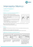
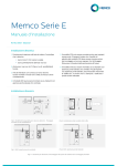
LMA – LINE MONITOR ALERT
USER’S MANUAL
Janus is a brand of Avire
Avire Inc
415 Oser Avenue, Suite Q, Hauppauge, New York 11788
Phone: 631 864 3699 Toll Free: 800 527 9156
Fax: 631 864 2631 Email: [email protected]
TABLE OF CONTENTS
SECTION
PAGE
OVERVIEW
3
INSTALLATION
4
OPERATION & TEST
5
TROUBLESHOOTING
7
LMA CONNECTION DIAGRAM
8
LMA MOUNTING DIAGRAM
9
LMX MOUNTING DIAGRAM
10
SPECIFICATIONS
11
WARRANTY POLICY
12
RETURN POLICY
13
2
Overview
The Line Monitor Alert Board (LMA) provides visual and
audible alerts when detecting a contact closure at the Alert
input. The Alert input of the LMA board can be connected to
the Phone line monitoring output (AUX2) of any Janus
Elevator Products ADA phone that includes it. This will allow
monitoring the status of the phone line on a Janus Elevator
phone or any other ADA phone equipped with such output.
If more then one ADA phone needs to have the phone line
monitored then the LMA should be used in conjunction with
the Line Monitor Expansion Board (LMX) which will support
up to 10 ADA phones. If more then 10 phones are used then
you could use multiple Expansion Boards and connect the
Alert Output of one Expansion Board to any of the Inputs of
another Expansion Board.
LMX
If the ADA phone(s) are connected to an EMS5 call director
then you should also use the Line Monitor Expansion Board
(LMX) and connect the AUX1 of the EMS5 to any of the
inputs of the LMX board and the ADA phones to the rest of
the inputs.
3
Installation
1. The LMA require 1 pair of wires from the Phone Line
Monitoring output (AUX2) of the ADA elevator phone to
the LMA Alert input. (See Figure 1)
2. The LMX require 1 pair of wires from the Phone Line
Monitoring output (AUX2) of each ADA elevator phone to
each input of the LMX and 1 pair of wires from the LMA
Alert input to the LMX Alert output. (See Figure 1)
3. The LMA / LMX system requires 12-24VDC/0.5A to
operate. The Power terminal is not polarity sensitive.
Note 1: Cabling can be inexpensive 18-24 gauge pair cable.
Note 2: If the Phone line Monitoring output of the ADA
elevator phone is normally close (NC) instead of the
standard normally open (NO) output you can install a jumper
at the “NC” location next to the Alert input connector(s) of
the LMA or LMX units.
OPTIONAL: If an LMX unit is provided Install it on the wall or
flat surface with (4) 8-32 screws using the (4) holes on the
sides of the unit. (See Figure 3)
4
Operation & Test
1. The LMA and LMX boards are both equipped with
Power / Board status LED. When the Board is first
powered up the LED will flash rapidly to indicate
Resetting and then flash slower to indicate normal
operation. If you need to reset the boards without
removing power you can press and hold the
“Test/Reset” button for at least 5 seconds.
2. If the phone line from a Janus Elevator Products
ADA phone equipped with a phone line monitoring
relay is disconnected or shorted the AUX2 Output of
the ADA phone will close within 10 minutes.
3. The LMA Board will detect an Alert Input closure
and it will trigger the Audible and Visual Alarms.
4. The LED(s) will flash and the Piezo Buzzer will emit
a beep every 9 seconds. The volume of the Piezo
Buzzer is set at optimal Level at the factory but can
be adjusted using the “VOL” potentiometer on the
LMA board.
5. The Piezo Buzzer can be silenced only by
authorized personnel if the “Key switch Reset” input
is closed. The LED(s) will continue to flash until the
phone line is re-connected or fixed on the ADA
phone.
6. If an LMX board is used the user can also identify
which ADA phone has a phone line issue by
checking the LED next to each input. If the LED is
“ON” on any of the Inputs it will indicate a phone line
failure of an ADA phone connected to this input.
(The LEDs are located inside the LMX enclosure)
5
Quick Test
•
To Test the LMA or the LMX Boards you can press
and release the “Test/Reset” button. On the LMA
Board you will see the LED(s) flashing and you will
also you hear the Piezo Buzzer beep at least twice
(Once every 9 seconds) to indicate an active Alert
Input. On the LMX Board you will see the LED of
each input from 1 to 10 light up for 1 second to
indicate an Active Input and the Alert Output will
then close accordingly. If the LMX is connected to
the LMA while performing this test you can test both
systems at once.
Note: This Test will only Test the functionality of the LMA
and LMX boards. Please refer to the “Complete System
Test” below to test the entire phone line monitoring
system.
Complete System Test
•
In order to test the entire system you must first make
sure everything is connected and powered up
according to the Installation Instructions of this
manual.
•
Remove the phone line from the ADA phone and
within 10 minutes the Alert Input of the LMA board
will close and this should cause the LED(s) to flash
and the Piezo Buzzer to sound. (If the LMX is also
used it will close the Alert input of the LMA board if
any of it’s 10 inputs is closed)
•
Activate the Key switch Input on the LMA board to
make sure you can silence the Piezo Buzzer but
make sure that the LED(s) continue to flash.
•
To turn “OFF” the LED(s) and the Piezo Buzzer on
the LMA board Re-connect the phone line to the
ADA phone.
6
Troubleshooting
1. If the LMA / LMX do not turn ‘ON’ make sure that the
wall transformer is plugged into 110VAC outlet, and
measure the voltage on the “POWER” connector inside
the LMA / LMX unit. The voltage should read about 1224VDC. The “POWER” connection is not polarity
sensitive.
2.
If the phone line is removed from the ADA phone and it
does not trigger an alarm first check the connections
according to diagram on Figure 1. If all connections are
good make sure you test the AUX2 Line Monitoring
output of the ADA phone by removing the phone line
and wait about 10 minutes until this input will close. If
this input does not close make sure you have 12-24VDC
supplied on the “PWR” connector of the ADA phone.
This connector is polarity sensitive. If all checks good
replace ADA phone and repeat test.
3. If the LMA is activated but the phone line on the ADA
phone is good disconnect the Alert Input wires from the
LMA board to see if that stops the alarm. If the Alarm
does not stop cycle power on the LMA board or press
and hold the Test/Reset button onboard for at least 5
seconds to reset the LMA board. If the Alarm does stop
when the Alert input wires are disconnected then you
must check for a short on the wiring or a fault on the
AUX2 Line monitor output of the Janus Elevator
products ADA phone.
Notes:________________________________________________
_____________________________________________________
_____________________________________________________
_____________________________________________________
_____________________________________________________
_____________________________________________________
7
Figure 1
LMA CONNECTION DIAGRAM
8
Figure 2
LMA MOUNTING DIAGRAM
9
Figure 3
LMX MOUNTING DIAGRAM
10
Specifications
LMA
Mechanical:
• Size: 10.5” H X 5” W X 3.1” D
• Weight: 4lbs
Electrical:
• Operating Voltage: 12-24 VDC
• Operating current: 400mA
• Supplied with standard 12VDC/0.5A transformer
• Operating Temperature Range 0 to 70 degrees C
• Storage Temperature Range: -20 to 70 degrees C
• Relative Humidity: Up to 95% (non-condensing)
LMX
Mechanical:
• Size: 7 1/4” H X 4 5/8” W X 1 3/8” D
• Weight: 0.5lbs
Electrical:
• Operating Voltage: 12-24 VDC
• Operating current: 150mA
• Supplied with standard 12VDC/0.5A transformer
• Operating Temperature Range 0 to 70 degrees C
• Storage Temperature Range: -20 to 70 degrees C
• Relative Humidity: Up to 95% (non-condensing)
11
Warranty Policy
Avire Inc. warrants its products to be free from defect in
materials and workmanship under normal use and service
for 24 months from date of purchase. Seller’s obligation shall
be limited to repairing or replacing, at its option, free of
charge for materials or labor any product which proves
defective in materials or workmanship under normal use and
service. Avire shall not be responsible for any damage to the
unit incurred during installation. Seller shall have no
obligation under this Limited Warranty or otherwise if the
product is altered or improperly repaired or serviced by
anyone other than Avire factory service. For warranty
service, contact Avire at 631-864-3699 or 800-527-9156.
THERE ARE NO WARRANTIES, EXPRESS OR IMPLIED,
OF MERCHANTABILITY, OR FITNESS FOR A
PARTICULAR PURPOSE OR OTHERWISE, WHICH
EXTEND BEYOND THE DESCRIPTION ON THE FACE
HEREOF. IN NO CASE SHALL SELLER BE LIABLE TO
ANYONE FOR ANY CONSEQUENTIAL OR INCIDENTAL
DAMAGES FOR BREACH OF THIS OR ANY OTHER
WARRANTY, EXPRESS OR IMPLIED, OR UPON ANY
OTHER BASIS OF LIABILITY WHATSOEVER, EVEN IF
THE LOSS IS CAUSED BY THE SELLER’S OWN
NEGLIGENCE OR FAULT.
12
Return Policy
During installation, if a product does not appear to function
properly the installer must call the Avire Technical Support
Unit at (800) 527-9156, Monday through Friday. If the
technician determines that the product is not functioning, an
RA (Return Authorization) number will be issued, allowing
the installer to return the product directly to Avire for repair,
replacement or credit. Returns with no fault found, will result
in a bench charge plus shipping costs. Returns without an
RA number will result in a restocking charge of 25% or more
plus shipping costs.
Need Technical Assistance?
Call 1-800-527-9156
13