1
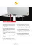
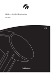
GB/US . . . . GH3/GH3+ Ceiling Hoist
Vers. 2.00
© Guldmann GB/US-06/2009 • # 550216
GH3 Lifting modules, version type nomenclature
Guldmann Product
hoist type line
Load in
kg
Number
of lifting
straps
Number
of lifting
motors
Number of Scale
horizontal module
drive
motors
CLM
module
Service
module
User
interface
GH3
xxx
x
x
x
x
x
x
x
200
1
1
1
250
1
1
1
250
1
1
1
300
1
2
2
None : 0
Scale: 1
None : 0
CLM : 1
None : 0
Service: 1
Hand
control: 0
350
1
2
2
250
2
2
0
500
2
4
0
Y
Z
Z
Z
(x)
GH3
+
Twin
© Guldmann GB/US-06/2009 • # 550216
GH3
X
IR
Q
Q
Q
Q
:1
GH3/GH3+ Ceiling Hoist
Item nos:
xxxx
1.00. . . . . . . . . Purpose and use. . . . . . . . . . . . . . . . . . . . . . . . . . . . . . . . . . . . . . . . . . . . . . 6
1.01. . . . . . . . . Manufacturer. . . . . . . . . . . . . . . . . . . . . . . . . . . . . . . . . . . . . . . . . . . . . . . . . . 6
1.02. . . . . . . . . Purpose. . . . . . . . . . . . . . . . . . . . . . . . . . . . . . . . . . . . . . . . . . . . . . . . . . . . . . 6
1.03. . . . . . . . . Important/Precautions. . . . . . . . . . . . . . . . . . . . . . . . . . . . . . . . . . . . . . . . . . . 6
1.04. . . . . . . . . Load limits on GH3 system. . . . . . . . . . . . . . . . . . . . . . . . . . . . . . . . . . . . . . . 7
1.05. . . . . . . . . Unpacking and Preparation. . . . . . . . . . . . . . . . . . . . . . . . . . . . . . . . . . . . . . . 7
1.06. . . . . . . . . Placing a new Hoist in an existing rail system . . . . . . . . . . . . . . . . . . . . . . . . 7
1.07. . . . . . . . . Power supply. . . . . . . . . . . . . . . . . . . . . . . . . . . . . . . . . . . . . . . . . . . . . . . . . . 8
1.08. . . . . . . . . Installation of the lifting hanger before use. . . . . . . . . . . . . . . . . . . . . . . . . . . 9
1.09. . . . . . . . . Lifting sling. . . . . . . . . . . . . . . . . . . . . . . . . . . . . . . . . . . . . . . . . . . . . . . . . . . 10
1.10. . . . . . . . . Swing kit. . . . . . . . . . . . . . . . . . . . . . . . . . . . . . . . . . . . . . . . . . . . . . . . . . . . . 12
1.11. . . . . . . . . Using swing kit in doorway . . . . . . . . . . . . . . . . . . . . . . . . . . . . . . . . . . . . . . 13
1.12. . . . . . . . . GH3 with horizontal drive motor . . . . . . . . . . . . . . . . . . . . . . . . . . . . . . . . . . 14
1.13. . . . . . . . . GH3 with horizontal drive motor and infrared remote (IR) control. . . . . . . . . 14
2.00. . . . . . . . . Description of functions. . . . . . . . . . . . . . . . . . . . . . . . . . . . . . . . . . . . . . . 14
2.01. . . . . . . . . Pictograms. . . . . . . . . . . . . . . . . . . . . . . . . . . . . . . . . . . . . . . . . . . . . . . . . . . 15
2.02. . . . . . . . . Indicator lamps and audio signals. . . . . . . . . . . . . . . . . . . . . . . . . . . . . . . . . 15
2.03. . . . . . . . . Operation. . . . . . . . . . . . . . . . . . . . . . . . . . . . . . . . . . . . . . . . . . . . . . . . . . . . 16
2.04. . . . . . . . . Supplementary modules, GH3+. . . . . . . . . . . . . . . . . . . . . . . . . . . . . . . . . . . 18
. . . . . . . . . . . . . Menu structure, Supplementary modules GH3+. . . . . . . . . . . . . . . . . . . . . . 18
2.05. . . . . . . . . Configuration of supplementary modules, GH3+. . . . . . . . . . . . . . . . . . . . . . 20
2.06. . . . . . . . . Scale module (GH3+ with integrated scale module) . . . . . . . . . . . . . . . . . . 21
2.07. . . . . . . . . CLM module (GH3+ with statistical function for management use) . . . . . . . 24
2.08. . . . . . . . . Service module (GH3+ with service module) . . . . . . . . . . . . . . . . . . . . . . . . 26
2.09. . . . . . . . . Safety functions. . . . . . . . . . . . . . . . . . . . . . . . . . . . . . . . . . . . . . . . . . . . . . . 28
2.10. . . . . . . . . Charging/connection . . . . . . . . . . . . . . . . . . . . . . . . . . . . . . . . . . . . . . . . . . . 30
2.11. . . . . . . . . Accessories. . . . . . . . . . . . . . . . . . . . . . . . . . . . . . . . . . . . . . . . . . . . . . . . . . 30
4.00. . . . . . . . . Maintenance and storage. . . . . . . . . . . . . . . . . . . . . . . . . . . . . . . . . . . . . . 31
4.01. . . . . . . . . Cleaning. . . . . . . . . . . . . . . . . . . . . . . . . . . . . . . . . . . . . . . . . . . . . . . . . . . . . 31
4.02. . . . . . . . . Storage . . . . . . . . . . . . . . . . . . . . . . . . . . . . . . . . . . . . . . . . . . . . . . . . . . . . . 31
4.03. . . . . . . . . How to prevent/avoid corrosion?. . . . . . . . . . . . . . . . . . . . . . . . . . . . . . . . . . 31
4.04. . . . . . . . . The owner’s daily maintenance duty. . . . . . . . . . . . . . . . . . . . . . . . . . . . . . . 31
4.05 . . . . . . . . Disposal of the GH3 including batteries . . . . . . . . . . . . . . . . . . . . . . . . . . . . 32
5.00 . . . . . . . . Service and lifetime. . . . . . . . . . . . . . . . . . . . . . . . . . . . . . . . . . . . . . . . . . . 32
5.01. . . . . . . . . Lifetime . . . . . . . . . . . . . . . . . . . . . . . . . . . . . . . . . . . . . . . . . . . . . . . . . . . . . 32
5.02. . . . . . . . . Safety/service inspections. . . . . . . . . . . . . . . . . . . . . . . . . . . . . . . . . . . . . . . 32
5.03. . . . . . . . . Troubleshooting. . . . . . . . . . . . . . . . . . . . . . . . . . . . . . . . . . . . . . . . . . . . . . . 33
© Guldmann GB/US-06/2009 • # 550216
3.00. . . . . . . . . Transport and storage. . . . . . . . . . . . . . . . . . . . . . . . . . . . . . . . . . . . . . . . . 31
6.00. . . . . . . . . Classification. . . . . . . . . . . . . . . . . . . . . . . . . . . . . . . . . . . . . . . . . . . . . . . . 33
7.00. . . . . . . . . Certificates. . . . . . . . . . . . . . . . . . . . . . . . . . . . . . . . . . . . . . . . . . . . . . . . . . 35
8.00. . . . . . . . . Technical specifications. . . . . . . . . . . . . . . . . . . . . . . . . . . . . . . . . . . . . . . 35
9.00. . . . . . . . . EC-Declaration of conformity. . . . . . . . . . . . . . . . . . . . . . . . . . . . . . . . . . . 39
© Guldmann GB/US-06/2009 • # 550216
. . . . . . . . . . . . . USA and countries outside the EU . . . . . . . . . . . . . . . . . . . . . . . . . . . . . . 40
A.. . . . . . . . . . . Users guide. . . . . . . . . . . . . . . . . . . . . . . . . . . . . . . . . . . . . . . . . . . . . . . . . . 40
B. . . . . . . . . . . Warranties. . . . . . . . . . . . . . . . . . . . . . . . . . . . . . . . . . . . . . . . . . . . . . . . . . . 40
1.00
Purpose and use
1.01
Manufacturer
V. Guldmann A/S
Graham Bells Vej 21-23A
DK-8200 Århus N
Tel. + 45 8741 3100
Fax. + 45 8741 3131
www.guldmann.com
1.02
Purpose
The GH3 is a ceiling-mounted hoist, which covers the need for lifting or
moving a person in hospitals, nursing homes, institutions, swimming pools,
riding schools and private homes.
•
•
•
•
•
•
1.03
•
•
•
•
•
•
Important/Precautions
Read the instructions carefully before using the GH3 and in connection
with cleaning and service of the hoist.
The GH3’s maximum load must never be exceeded.
The GH3 may only be used to lift a person.
The red strap for the emergency stop and the emergency lowering must
be adjutsed to the helpers reach, and must not be removed.
The GH3 must not be used where there is a risk of it being splashed with
water.
If a defect appears during use of the GH3, stop using the hoist and contact
the Guldmann Service Team for repairs. The GH3 is controlled by a microprocessor PCB, which can be damaged by static electricity if touched without the
necessary precautions, (see point 1.07) The electronics may only be serviced
by Guldmann approved service technicians.
© Guldmann GB/US-06/2009 • # 550216
•
•
Conditions for use
The use of the GH3 is subject to the following:
The GH3 should only be used by trained personnel.
The maximum nominal load, 200 kg (440 lbs), 250 kg (550 lbs), 300 kg
(660 lbs), 350 kg (770 lbs) respectively, must not be exceeded.
The instruction offered by Guldmann to all customer groups in connection
with the purchase of a ceiling-mounted hoist has been received.
The helper pays attention to the well-being of the user when using the
hoist.
The hoist is used in rail systems which are installed, tested and approved
according to Guldmann’s stipulation.
Only technicians who have been certified by Guldmann may install and
test the rail systems.
The hoist is used with the Guldmann lifting hanger or with other suitable
hanger (section 1.08).
The hoist is used with a Guldmann lifting sling or with other suitable slings
(section 1.09).
1.04
Load limits on GH3 system
Read the label which indicate the maximum load limits for each component.
The components, e.g. lifting hanger, lifting sling, etc. labelled with the lowest
load limit determines the maximum load limit for the entire system.
This maximum load limit must not be exceeded.
Please note that the max load may change when different components are
used, such as lifting hangers, lifting slings, etc.
1.05
Unpacking and Preparation
Visual check of the GH3.
If the GH3 is thought
to be damaged upon
reception, the GH3 must
not be used before it
has been checked and
approved by a qualified
person or the Guldmann
Service Team.
.
2.
3.
4.
5.
1.06
Contents of the box
GH3 hoist
Hand control
Transformer
Manual
Label for rail system
1
2
3
Placing a new GH3 Hoist in an existing rail system
© Guldmann GB/US-06/2009 • # 550216
Please notice, placing a new GH3 hoist in an existing rail system it must
be ensured that:
•
The rated max load of the rail system, must be equal or higher than the
max load of the new hoist.
– If there is no max load mentioned on the rail system, the rail system
must then be checked according to the guideline in the installation
manual (distance between bracket according to max load)
– If the brackets are not visible, then a load test with 1,5 x max load of
the hoist must be performed. The deflection of rails must not be higher
than 1/200 of the length of the rail.
– If it is not possible to do any of the above mentioned, please contact
Guldmann or their representative
•
If the rail system can not be rated to the same max load as the hoist,
then extra brackets must be installed according to the installation
manual (distance between bracket according to max load).
Class I equipment
Fixed rail systems are class I equipment and must be installed by a qualified
technician or by Guldmann Service Team.
Equipment is disconnected from Supply Mains by breaking the mains breaker
switch.
Class II equipment
Mobile equipment is class II epuipment (marked with double-encassed
symbol) and can be connected to the mains direct by the user.
Equipment is disconnected from Supply Mains by detaching the mains plug
from the wall outlet.
Emergency stop device
The emergency stop device must be reset in order to connect power to the
product. To do this, push the yellow reset button (see point 2.09).
Power supply
GH3 is equipped with batteries that require regular recharging. The power
supply for charging and the battery charging point must be connected by a
qualified engineer or by Guldmann Service Team.
The transformer supplied must always be used.
Safety concerning static electricity (ESD)
Service technicians and installers must use an ESD-safety package
consisting of a mat, a ground wire, and a bracelet. The technician/installer
connects the mat to a grounding point, for instance a radiator or a water pipe.
The technician/installer must then put on the bracelet and connect it to the
mat. If it is not possible to find a grounding point, the mat and the bracelet
must be used as a minimum.
Only then is it allowed to work with the PC Board or components where it is
possible to come into contact with the PC Board.
© Guldmann GB/US-06/2009 • # 550216
1.07
1.08
Installation of the lifting hanger before use
Lifting hangers from other .
manufacturers
Guldmann shall not be liable for faults
or accidents that may occur as a result
of using lifting hangers made by other
manufacturers.
Fig. 1
If there is any doubt about the
selection or use of a lifting hanger,
please contact your supplier.
The lifting hanger can be installed to
the lifting strap without the use of any
tools.
. Hold the lifting hanger in the right hand
and press the yellow button using the
thumb as shown (Fig. 1)
Fig. 2a
2. Insert the strap attachment in
the slot on the lifting hanger top cover
with the open side facing down
(Fig. 2a, 2b) and release the yellow
button (Fig. 2c)
3. Rotate the strap attachment to a
vertical position (Fig. 3)
Fig. 2b
4. Check that the yellow button has returned
to its locked position by checking that it is
flush with the cover of the lifting hanger
and that the strap attachment can rotate
freely.
© Guldmann GB/US-06/2009 • # 550216
Fig. 2c
Fig. 3
Lifting sling
A lifting sling with four to six lifting straps designed for mounting on hooks
should be used when using a Guldmann lifting hanger. Place the straps on
the hooks. Make sure that the rubber safety catch returns to its start position,
so the straps can not unintentionally fall off.
Slings made by other manufacturers
Guldmann shall not be liable for faults or accidents that may occur as a
result of using lifting slings made by other manufacturers.
If there is any doubt about the selection or use of a lifting sling,
please contact your supplier.
Guldmann shall not be liable for faults or accidents due to incorrect use of
the lifting sling, or for reasons of inadequate attention on the part of the carer
or user.
Working with the GH3
The GH3 runs easily in the rail system and does not have any special
requirements for space or power in connection with moving. Attention can
thus be fully focused on the user’s functional level and the helper’s technique.
If the hoist is used correctly, the user should only be lifted to the extent that
she/he is clear of the surface and should be moved at this height.
Attaching the lifting sling
Place the straps from the lifting sling on the hooks on the lifting hanger. Start
with the uppermost set of straps (from the back) and then take the lowest set
of straps (from the legs).
Important!
Be careful when applying the lifting sling. Check that the straps have been
pulled completely through the rubber safety catch and into place in the lifting
hanger’s hooks before starting lifting the user.
10
© Guldmann GB/US-06/2009 • # 550216
1.09
Lifting to and from a seated position
When lifting a user from e.g. a wheelchair, move the GH3 towards the person
to be lifted.
The lifting hanger should be at the same height as the user’s chest and
should not be moved further in over the user than to approximately mid-thigh
position.
Place the lifting hanger parallel to the user’s shoulders.
Place the lifting sling behind the user’s back between the back of the chair
and the user’s back.
The centre band of the lifting sling should follow the user’s spine. As for the
slings type Active the strap showing the size of the sling should be opposite
the spine. Lead the leg straps along the outer sides of the user’s shins and
beneath the thighs between the hollow of the knees and the hip joints. Cross
the leg straps in front of the user.
All four lifting straps are now ready to be attached. The lifting sling can now
be mounted on the lifting hanger.
Lifting to and from lying position in bed
Bring the lifting hanger over the centre of the person to be lifted.
Place the lifting hanger parallel to the user’s shoulders.
Turn the user onto his or her side. The High Back sling should be placed so
that its top is at the same height as the top of the user’s head. Now position
the sling over the user so that the centre band follows the user’s spine. Turn
the user onto his or her back and pull out the remaining part of the lifting
sling. Place the leg straps beneath the user’s thighs and cross them. All four
lifting straps are now ready to be attached and the lifting sling can now be
mounted on the lifting hanger. It is an advantage to elevate the head of the
bed so that the user is sitting up.
© Guldmann GB/US-06/2009 • # 550216
Only persons who have received competent instruction regarding the use of
lifting equipment and fitting of slings should use the hoist.
Important!
Plan the move. Avoid leaving the user in the lifting sling unattended. The GH3
lifts quickly and powerfully. Before lifting, check that the user is completely
free of his/her surroundings. The user’s head, arms, hands and feet must not
be in danger of becoming trapped. Be careful with any tubes and wires that
are attached to the user. Check that the hand control and hand control cable
is free of hanger, patient and other object before the hoist is activated up or
down moved.
11
Swing kit
The swing function is used in conjunction
with a transfer e.g. through a door from
one lifting module to another.
Note: The swing adapter must be ordered
separately.
Fig. 1
Installation of swing adapter
. Before starting a lift involving a swing
transfer the swing adapter (Fig. 1)
must be installed on the lifting hanger.
(Fig. 2 to 5)
Fig. 2
2. Hold the lifting hanger in the right hand
and press the yellow button using the
thumb (Fig. 2)
3. Insert the swing adapter in the slot on the
lifting hanger top cover with the open side
facing down (Fig. 3a, 3b) and release the
yellow button.
Fig. 3a
4. Rotate the swing adapter to a vertical
position (Fig. 4)
5. Check that the yellow button has returned
to its locked position by checking that it is
flush with the cover of the lifting hanger
and that the swing adapter can rotate
freely.
6. Install the strap attachment to the swing
adapter by sliding the open side of the
strap attachment over the flat area of the
swing adapter (Fig. 5)
7. Rotate the strap attachment and ensure
that it moves up on the circular portion of
the swing adapter (Fig. 6)
Fig. 3b
Fig. 4
Fig. 5
Fig. 6
12
© Guldmann GB/US-06/2009 • # 550216
1.10
1.11
Using swing kit in doorway
. Bring the two hoist as close together as
possible. Adjust the height of the lifting
hanger on hoist B so that the transfer can
be done without the user touching the
floor during the transfer from one hoist to
another.
2. Take the free lifting strap from hoist A
and secure it to the swing adapter on the
lifting hanger (see 1.10 figures 5 and 6).
In order to lower the free lifting strap on
hoist A a slight pull must be applied to the
strap.
A
B
A
B
4. Disconnect the lifting strap on hoist B
from the lifting hanger and raise the strap
on hoist B out of the way.
A
B
5. Move the lifting hanger from hoist A to
operating height and the doorway transfer
is complete.
A
B
3. Lower the lifting hanger using hoist B
while lifting the strap on hoist A to perform
the swing transfer. The transfer has been
completed when there is no load on the
lifting strap on hoist B
© Guldmann GB/US-06/2009 • # 550216
A
13
1.12
GH3 with horizontal drive motor
The GH3 with horizontal drive motor can operate in the rail system.
Be aware that the drive motor takes time to both accelerate and brake
the hoist.
It is possible to position the hoist with horizontal driving motor with a high
degree of accuracy by a brief activation of the hand control.
The GH3 with horizontal drive motor runs on its own power and it should
not be pulled through the rail system.
1.13
GH3 with horizontal drive motor and infrared remote (IR) control
The GH3 has an integrated IR receiver which is controlled by the IR
remote control.
The hand control should be left attached to the hoist.
This means that the hoist can always be operated, in the the event that
the IR remote control is mislaid or the battery is uncharged.
Description of functions
Information panel on the GH3 bottom surface.
Lamp indicator
RESET
14
© Guldmann GB/US-06/2009 • # 550216
2.00
2.01
Pictograms
Emergency stop
Emergency lowering function
RESET
Reset emergency stop
Direction of travel (horizontal drive motor) denoted by grey arrow
2.02
Indicator lamps and audio signals
Status
Indicator
lamps
© Guldmann GB/US-06/2009 • # 550216
Communication
3 x Beep after 60 sec
Horizontal drive motor
Green
No charging Yellow,
after 15 sec
Emergency lowering
All OK
Down
Off
Possible GH3
Functions
Up
Off
– stand by
Audio signals
x
x
x
x
x
x
x
x
x
x
x
x
x
x
x
Low battery
Yellow
Fault on
hoist
Yellow
Beeps at button activation
Battery
critical low
Yellow
Beeps at button activation
that is not permitted
x
Over load
Yellow
Beeps at button activation
x
15
x
x
x
x
x
Operation
Hand control
The GH3 is switched on automatically when
a button on the hand control is pressed.
1
The GH3 is switched off automatically after
approx. 8 minutes without activation.
2
GH3
. Lift
2. Lower
GH3 with horizontal drive motor
. Lift
2. Lower
3. Movement in the direction of the arrow
on the GH3 information panel.
4. Movement in the direction opposite to
the arrow on the GH3 information panel.
GH3+
1. Lift
2. Lower
5. Function selection button
(section 2.05, supplementary modules)
6. Function selection button
(section 2.05, supplementary modules)
7. PDA interface (mini USB) x)
1
3
4
2
5
1
6
2
7
GH3+ with horizontal drive motor
. Lift
2. Lower
3. Movement in the direction of
the arrow on the GH3 information panel.
4. Movement in the direction opposite to
the arrow on the GH3 information panel.
5. Function selection button
(section 2.05, supplementary modules)
6. Function selection button
(section 2.05, supplementary modules)
7. PDA interface (mini USB) x)
x) Accessories to CLM module
(see Supplementary modules, GH3+ (section 2.04))
16
5
1
3
6
4
2
7
© Guldmann GB/US-06/2009 • # 550216
2.03
Parking the hand control
When the hand control is not in use it can be placed on the lifting hanger.
Infrared remote control
. Lift
2. Lower
3. Movement in the direction
of the arrow on the GH3
information panel
4. Movement in the direction opposite
to the arrow on the GH3
1
3
© Guldmann GB/US-06/2009 • # 550216
Note:
In order for the GH3’s lowering function
to work, the strap must be carrying a
load equal to the minimum capacity for
Guldmann’s lifting hanger.
Transport/running in the rail system
The GH3 is manually pushed forward in the rail system by the helper.
The GH3 with horizontal drive motor will run in the rail system when
activated by the hand control/remote control.
17
2
4
Supplementary modules, GH3+
There are various supplementary modules for the GH3+
•
Scale module (GH3+ with integrated scale)
•
CLM module (GH3+ with statistical function for management use)
•
Service module (GH3+ with Service module)
Menu structure, Supplementary modules GH3+
(Detailed description follows in sections 2.05-2.09)
Scale
CLM
Next service
KG
2008.04.22
Start
OK
Scale
KG
248.0
Zero
Setup
Exit
Show
Setup
CLM
1-5
Lifetime
total lifts
987
Units
Next
Exit
Chang
Pop-ups
Next
service
2008.04.22
Service date
exceeded
call service
OK
Exit
Low battery
OK
No charging
OK
Scale
KG
0.0
Zero
Exit
CLM
2-5
Lifetime
heavy lifts
232
Next
Exit
CLM
3-5
Last week
total lifts
60
Critical low
battery
Next
OK
Exit
Units
Chang
Units
Chang
CLM
4-5
Lifts per
week avg
72
Fault hoist
Next
OK
CLM
Exit
5-5
Hoist ID
Hoist #1
Next
18
Exit
© Guldmann GB/US-06/2009 • # 550216
2.04
LM
Next service
Setup
2008.04.22
how
Setup
LM
1-5
Lifetime
total lifts
987
Units
ext
Exit
LM
2-5
Lifetime
heavy lifts
232
Next
Exit
LM
3-5
Last week
total lifts
60
ext
Exit
ext
LM
© Guldmann GB/US-06/2009 • # 550216
LM
4-5
Lifts per
week avg
72
Exit
Language
KG
Change
Units
OK
Units
Change
Change
Language 1-7
Language 5-7
Change
Change
OK
Change
Francaise
Change
OK
Language 3-7
English
Change
OK
5-5
Hoist ID
Hoist #1
Next
OK
Language 7-7
Svenska
Change
OK
Language 6-7
Deutsch
OK
OK
Espanol
Language 2-7
KG
Change
Italianio
Dansk
lbs
Change
Language 4-7
English
Exit
19
2.05
Configuration of supplementary modules, GH3+
Before the GH3+ is put into use, the hoist must be configured. Configuration
covers language (Scale module/CLM module/Service module) and the unit for
specification of weight (Scale module).
Factory setting: Language:
Unit of weight: English (UK)
kg
Configuration of supplementary modules takes place from the GH3+
hand control.
Setting the language
Scale
Statistics
Next service
Start
Language
English
KG
2008.04.22
Show
Setup
Change
. Press any key on the GH3+ hand control to activate the hoist.
When the hoist is activated, the display on the hand control is switched on
and the Guldmann logo “G” appears.
2. Select “Menu” using the function key located immediately below the display
and then select “
” until the “Setup” menu appears in the display.
3. Select “Setup” and then “
display.
” until the “Language” menu appears in the
4. Select “Change” until the preferred language appears in the display, and
confirm the selection by pressing “OK”.
5. Then return to “Setup”. Select “
20
” to return to the start menu.
© Guldmann GB/US-06/2009 • # 550216
Menu
Setup
Setting the units, kg/lbs (Scale module)
Scale
Statistics
Next service
KG
Menu
Setup
Scale
Setup
Change
KG
2008.04.22
Start
Show
. Press any key on the hand control to activate the hoist.
When the lifting module is activated, the display on the hand control is
switched on and the Guldmann logo “G” appears.
2. Select “Menu” using the function key located below the display
3. Then select “
” until the “Setup” menu appears in the display.
4. Select “Setup” and then “
” until the “Units” menu appears in the display.
5. Select “Change” to switch between the units kg and lbs, and confirm the
selection by pressing “OK”.
6. Select “
” to return to the start menu.
7. The display in the hand control switches off automatically after use
(approx. 8 min). (See the complete menu summary, section 2.04,
Supplementary modules, GH3+)
2.06
Scale module (GH3+ with integrated scale module)
The GH3+ with scale module (option) provides the facility to determine the
user’s weight.
Warning!
The integrated scale in GH3+ is not approved to determine mass in medical
practice, including the weighing of patients in connection with health monitoring, diagnosis and medical treatment.
© Guldmann GB/US-06/2009 • # 550216
(The provisions for medical weighing are specified in accordance with EEC
Directive 90/384)
Shock effects
The GH3+ with scale module includes high-sensitive sensors to register mass
corresponding to the nominal recommended load. The sensors are highly
sensitive and can be damaged by the effects of shock, for example pulling
the GH3+ at extreme speed into an end stop.
Operation
Always reset the GH3+ scale module before weighing takes place. When
resetting the unit, the lifting hanger and the desired lifting sling must be
attached under the hoist.
21
Resetting the unit (tara)
Scale
Scale
248.0
KG
Menu
KG
Start
Zero
Exit
Scale
KG
0.0
Zero
Exit
. Press any key on the hand control to activate the hoist.
When the lifting module is activated, a display on the hand control is
switched on and the Guldmann logo “G” appears.
2. Select “Menu” using the function key located immediately below the
display
3. Then select “
” until the “Scale” menu appears in the display.
4. Then select “Start”.
5. Park the hand control on the lifting hanger. (If the helper pulls the hand
control during weighing, this will affect the result of the weighing process).
6. When the lifting hanger with the lifting sling is at rest, select “Zero”
to reset the GH3+ scale module.
22
© Guldmann GB/US-06/2009 • # 550216
The scale module has now been reset and weighing can commence.
Weighing
Scale
Scale
248.0
KG
Menu
KG
Start
Zero
Exit
. Always reset the GH3+ scale module before weighing takes place, see section entitled “Resetting the unit”.
2. Place the lifting sling on the user and attach it to the lifting hanger.
3. Lift the user with care.
4. Park the hand control on the lifting hanger.
5. Select “Menu” using the function key located immediately below the
display and then select “ ” until the “Scale” menu appears in the display.
6. Then select “Start”.
7. When the sling and the user are at rest and hanging freely, the current
weight can be read on the display. (The weight can be read to an accuracy
of 1 decimal place).
8. Select “Exit” to return to the main menu.
© Guldmann GB/US-06/2009 • # 550216
Note:
The display in the hand control switches off automatically after use
(approx. 8 min.)
23
CLM module (GH3+ with statistical function for management use)
The GH3+ with CLM module (option) includes a management tool that saves
important information on the use of the lifting module and which can be used
to evaluate the system’s efficiency and utilisation, as well as to optimise
its use and hoist name/location.
The following data can be shown on the hand control’s display: number of
lifts, number of heavy lifts, number of lifts in last week, average number of
lifts per week.
As an additional option, by connecting a PDA/Net Book to the hand control it
is possible to gain access to a number of other saved data, e.g. the number
of lifts since the last strap change, number of critically low battery readings,
number of weighings, total lifting time, etc.
This information can be downloaded and used for further analysis.
(PDA/Net Book readouts requires a PDA/Net Book with Guldmann CLM
software).
Number of lifts, total
A lift is registered automatically when the following
events are registered simultaneously
• Hand control is activated
(Direction UP) for more than 5 seconds
• The load on the lifting strap is registered as
being within the range:
30 kg – Recommended load kg
(66 lbs – Recommended load lbs)
Total includes the number of lifts performed after
the lifting module was first taken into use.
Number of heavy lifts, total
A heavy lift is registered automatically when the
following events are registered simultaneously
• Hand control is activated (Direction UP) for
more than 5 seconds
• The load on the lifting strap is registered as being within the range:
150 kg – Recommended load kg
(330 lbs – Recommended load lbs)
Total includes the number of heavy lifts performed
after the lifting module was first taken into use.
Number of lifts, last week
The total number of lifts performed within the last
seven calendar days
Average number of lifts per week
Average number of lifts per week (performed after
the lifting module was first taken into use)
The data for “Number of lifts, last week” and “Average number of lifts
per week” can, if necessary, be reset using a PDA/Net Book.
24
© Guldmann GB/US-06/2009 • # 550216
2.07
Operation .
.
Scale
.
.
CLM
KG
Menu
Start
.
.
Show
.
CLM
1-5
Lifetime
total lifts
987
CLM
2-5
Lifetime
heavy lifts
232
CLM
3-5
Last week
total lifts
60
CLM
4-5
Lifts per
week avg
72
CLM
Next
Next
Next
Next
Next
Exit
1-5
Number
of lifts,
total
Exit
2-5
Number
of heavy lifts,
total
Exit
3-5
Number
of lifts last week
Exit
4-5
Average
numbers
of lifts per
week
5-5
Hoist ID
Hoist #1
Exit
5-5
Hoist ID
. Press any key on the GH3+ hand control to activate the hoist.
When the lifting module is activated, the display on the hand control
is switched on and the Guldmann logo “G” appears.
2. Select “Menu” using the function key located below the display.
3. Then select “
” until the “CLM” menu appears in the display.
4. Then select “Show”.
5. Then select “Next” until the required information appears in the display.
6. Select “Exit” to return to the main menu.
© Guldmann GB/US-06/2009 • # 550216
Note:
The display on the hand control will automatically revert to the screensaver
after approx. 8 min.
Accessories for the CLM module, GH3+
The CLM module includes an extended management menu which can be
operated via a PDA/Net Book (with Guldmann CLM software installed).
The PDA/Net Book is connected to the GH3+ hand control via a mini USB
plug located in the base of the hand control (see section 2.04).
Contact supplier or the Guldmann Service Team for further information about
CLM accessories.
25
Service module (GH3+ with service module)
The GH3+ with Service module (option) saves all of the information about
time and indication of next safety/service inspection.
The GH3+ with Service module specifies the date of the next safety/service
inspection.
Operation
Scale
CLM
KG
Menu
Next service
2008.04.22
Start
Show
. Press any key on the hand control to activate the hoist. When the lifting
module is activated, a display on the hand control is switched on and the
Guldmann logo “G” appears.
2. Select “Menu” using the function key located immediately below the display.
3. Then select “
display.
” until the “Next service:” menu item appears in the
4. Read off the date of the next safety/service inspection (Year, Month, Date).
26
© Guldmann GB/US-06/2009 • # 550216
2.08
Pop-Up’s for Service module (supplementary module)
There are two different Pop-Up’s (brief messages on the display) on the
GH3+ with Service module. These pop-up’s notify the user of upcoming
and exceeded dates for service inspections.
Both Pop-Up’s appear immediately after the hand control has been
switched on.
Pop-Up’s before and after “Service Date” .
.
Next service
Next service
Service done
2008.04.22
2009.04.22
.
.
.
.
.
. Pop-Up, 30 days
The next service inspection must be undertaken within 30 days.
Select “OK” to return to the main menu
(returns automatically after approx. 5 seconds).
Next service
If service is not performed
2008.04.22
Service date
exceeded
call service
Exit
2. Pop-Up, Service date exceeded
The date of the service inspection has been exceeded, contact the
Guldmann Service Team.
Select “Exit” to return to the main menu (returns automatically after
approx. 5 seconds).
© Guldmann GB/US-06/2009 • # 550216
Attention!
The hoist’s lifting function is switched off in connection with the second
Pop-Up “Service date exceeded”. The lifting module’s lowering
function can still be used.
Note:
The display on the hand control will automatically revert to the screensaver
after approx. 8 minutes.
27
2.09
Safety functions
The emergency stop and emergency lowering device should only be
used in an emergency
In the event that it is necessary to use the safety functions, the fault must
be identified and rectified before the GH3 is taken into use again.
Please contact your supplier.
Emergency stop
If the GH3 does not stop/react to the hand control when the GH3 is in use,
pull the red strap and all lifting/lowering/horizontal driving functions (except
emergency lowering) are deactivated.
When the emergency stop is activated, the hoist will not function. The green
lamp is switched off.
Reset emergency stop
Reset the emergency stop by pressing the yellow button on the bottom of the
hoist.
The yellow button that appears when the emergency stop is pulled, must be pressed manually
before the GH3 is ready for use.
After deactivating the emergency stop, activate
the hand control twice:
•
•
First to switch on the hoist
Then to initiate movement, e.g. lift/lower.
28
© Guldmann GB/US-06/2009 • # 550216
•
•
Emergency and lowering strap
The red strap has the following functions:
One pull: Emergency stop is activated.
Constant pull (2 steps): Emergency lowering is activated
Emergency lowering function, electric
If the GH3 fails, the electrical emergency lowering function is used to lower
the user safely. The emergency lowering function is operated by a constant
pull on the red strap that is used for the emergency stop.
When releasing the red strap, the emergency lowering function will be
replaced by the emergency stop.
Emergency lowering function, mechanical
If the electrical emergency lowering function in the GH3 fails, the emergency
lowering can be done mechanically.
. Remove the side covers.
Release the side covers from the top of
the hoist by means of a gentle push on
the fixing points on each side. The covers
are tipped free of the hoist and can be
removed.
2. Then release the hoist’s motor by turning
the handle bearing the words
“EMERGENCY DOWN”. This handle is
located immediately behind the side cover
and must be turned clockwise.
© Guldmann GB/US-06/2009 • # 550216
Note:
For hoists with a recommended load of
more than 250 kg (550 lbs), there are two
motors and therefore two handles to activate, one on each side.
29
3. When the brake(s) has/have been
released, the user will be lowered slowly.
If the total weight of the user and the lifting
accessories is low (e.g. less than 50 kg
(110 lbs), it may be necessary to help the
user down by turning the large belt wheel
located on the opposite side of the handle
and in the direction of arrow marked on
the belt wheel.
Note:
A GH3 with a recommended load of more than 250 kg (550 lbs) has two
motors, and therefore two belt wheels to activate, one on each side.
Warning!
After the mechanical emergency lowering function has been activated in the
GH3, the hoist MUST be serviced by a qualified technician or by the
Guldmann Service Team.
2.10
Charging/connection
The GH3 is automatically charged troughout in straight rails. This guarantees
the hoist functionality and maintains the batteries to ensure a long lifetime.
The indicator lamp on the bottom of the hoist turns yellow if the charge status
becomes low or if there is a complete interruption to the charging function.
The GH3 then has a limited number of lifts available at a time and must be
re-charged.
The transformer must be connected and switched on before charging can
take place. A green indicator lamp on the transformer indicates that it is
connected and switched on.
Accessories
Guldmann – ABC slings and lifting hangers
Obtain a special brochure from your distributor, manufacturer or at
www.guldmann.com
Extension strap
The extension strap is used where the distance between the lower part of the
rails and the floor exceeds 3,5 m (11’/7”). The extension strap is available as
an accessory.
Batteries
NiMH Battery 24V/2800mAh, Guldmann type number 550182.
Transformer
Transformer, Class 1, Guldmann item number 551468
Transformer, Class 2, Guldmann item number 550269 (EU),
550268 (US/CAN)
30
© Guldmann GB/US-06/2009 • # 550216
2.11
3.00
Transport and storage
Guldmann recommends that the GH3 is always transported and stored
in the original packaging.
Key to symbols on the GH3 packaging:
-10
14
40oC
104oF
30
70%
700
1060hPa
© Guldmann GB/US-06/2009 • # 550216
The GH3 should be stored at:
– Temperatures between -10 and +40°C / 14 and 104°F
– A relative air humidity of between 30 and 70 %
– An air pressure of between 700 and 1060 hPa
4.00
Maintenance and storage
4.01
Cleaning
Clean the GH3 with a damp cloth and mild handwash detergent.
Do not use strong acids, bases or alcohol to clean the GH3. Never clean
GH3 in an autoclave.
4.02
Storage
See 3.00
For long-therm storage, disconnect the battery plugs.
4.03
How to prevent/avoid corrosion?
When the GH3 is mainly used in an corrosive environment, e.g. swimming
pool, the hoist must be ordered with a special corrosion-preventive surface
treatment.
4.04
The owner’s daily maintenance duty
Check the lifting sling for wear and damage before use.
Do not use the lifting sling if it is damaged or defective.
Do not use the GH3 if the lifting strap is damaged or defective.
Contact your supplier and order a new lifting sling or a replacement of the
lifting strap. Replacement of the lifting strap must only be performed by
the Guldmann Service Team or by a qualified technician in accordance with
Guldmann’s instructions.
31
4.05 Disposal of the GH3 including batteries
Local and national regulations on environmentally correct recycling must be
observed.
Batteries (type NiMH) must always be delivered to an approved recycling
point.
5.00 Service and lifetime
5.01
Lifetime
The GH3 has an expected lifetime of 15 years, on the condition of coorect
use and correct service inspections, see section 5.02.
Replacement of components
Replacement of batteries, PCBs and lifting straps must be performed by a
qualified service technician or the Guldmann Service Team.
Safety/service inspections
In accordance with international standard EN/ISO 10535 “Hoist for the
transfer of disabled persons – Requirements and test methods” an inspection
should be performed on the hoist at least once a year.
Guldmann recommends that regular safety/service inspection is performed at
least once a year with regard to the pattern of usage.
Inspection of the GH3 must be performed by a qualified service technician or
the Guldmann Service Team.
In connection with the purchase of the GH3, Guldmann may offer a service
agreement for this inspection.
NB!
The GH3+ with service module may only be serviced by the Guldmann
Service Team or by a qualified service technician with access to the
PDA/Net Book with Guldmann software.
During the safety/service inspection a report must be prepared on what was
checked and replaced. Parts that are worn or defective must be replaced with
new parts from Guldmann. Spare parts drawings and documentation can be
obtained from the manufacturer or supplier.
Documentation/checklist regarding safety/service inspection can be obtained
from the manufacturer or supplier.
32
© Guldmann GB/US-06/2009 • # 550216
5.02
5.03
Troubleshooting
.
2.
3.
4.
6.00
The GH3 does not respond to the hand control’s keys
Check the emergency stop is not activated
Check the hoist has power supply
Check the transformer is switched on and connected to the rail system
Contact the Guldmann Service Team
Classification
CE marking
23W1
Medical equipment with respect to electrical shock, fire and mechanical
hazards only.
In accordance with UL 60601-1, CAN/CSA c.22.2 No. 601.1
Type B in accordance with UL/EN 60601-1
Read the manual before use
Must not be disposed of as standard household waste, must be recycled.
Class I equipment:
Class II equipment:
Permanent installation with protective ground
Non-permanent installation without protective ground
© Guldmann GB/US-06/2009 • # 550216
The equipment is not suitable for use in the presence of flammable mixtures.
Degree of protection against harmfull ingress of liquids (water)
Hoist
IP20
Hand control
IP44
Remote control
IP20
Transformer
IP20
33
Examples of serial number label
Lifting module
GH3 250 110 0000
max 250 kg / 550 lbs
Part no.
xxxxxx
Prod. date yyyy-mm-dd
Serial no. x x x x x
33V AC, 2.5 A, IP20
CONTINUOUS OPERATION
WITH SHORT-TIME LOADING
23 W 1
INTERNALLY POWERED
EQUIPMENT 24V DC
Barcode 128C
www.guldmann.com
Transformer Class 1
Type
Input
Input
Output
Prod. date
Serial no.
IP20
DK-13991
115V AC 50-60 Hz, 1A
230V AC 50-60 Hz, 0,5A
33V AC 2,5A
yyyy-mm-dd
xxxxx
23 W 1
www.guldmann.com
Barcode 128C
Transformer Class 2
Use within US/CAN
DK-14001
115V AC 50-60 Hz, 1A
33V AC 2,5A
yyyy-mm-dd
xxxxx
Type
Input
Output
Prod. date
Serial no.
IP20
23 W 1
DK-13992
230V AC 50-60 Hz, 0,5A
33V AC 2,5A
yyyy-mm-dd
xxxxx
www.guldmann.com
Barcode 128C
Lifting hanger
Barcode 128C
Hand control
Part no. x x x x x x
Edition x x x
Date
x x x x- x x- x x
IP44
max
300 kg/660 lbs
Part no.
Edition
Prod. date
Serial no.
23 W 1
www.guldmann.com
550316
xxx
yyyy-mm-dd
xxxxx
Barcode 128C
V. Guldmann A/S
www.guldmann.com
34
© Guldmann GB/US-06/2009 • # 550216
Type
Input
Output
Prod. date
Serial no.
IP20
Transformer Class 2
Use within EU
7.00
Certificates
UL 60601-1
EN/ISO10535
8.00
Technical specifications
UL No. 305250
HMI No. 08.49A
GH3 Lifting modules, version type nomenclature
Guldmann Product
hoist type line
Load in
kg
Number
of lifting
straps
Number
of lifting
motors
Number of Scale
horizontal module
drive
motors
CLM
module
Service
module
User
interface
GH3
xxx
x
x
x
x
x
x
x
200
1
1
1
250
1
1
1
250
1
1
1
300
1
2
2
None : 0
Scale: 1
None : 0
CLM : 1
None : 0
Service: 1
Hand
control: 0
350
1
2
2
250
2
2
0
500
2
4
0
Y
Z
Z
Z
(x)
GH3
+
Twin
GH3
X
GH3
+
IR
Q
Q
Q
Q
Example: GH3+ 350 122 1000
350
1
2
2
1
0
0
0
Hand control
w/o Service module
© Guldmann GB/US-06/2009 • # 550216
w/o CLM module
Scale module
2 horizontal drive motors
2 lifting motors
1 lifting strap
Safe Working Load SWL:
+
Ceiling hoist, type GH3
35
:1
Functions
Lifting capacity, SWL. . . . . . . . . . . . . . . . . . 200 kg (440 lbs), 250 kg (550 lbs)
300 kg (660 lbs), 350 kg (770 lbs)
Operation. . . . . . . . . . . . . . . . . . . . . . . . . . . . . . . . . . . . . . . . . Hand control / IR
Sound level . . . . . . . . . . . . . . . . . . . . . . . . . . . . . . . . . . . . . . . . . . . . . 52 dB (A)
Horizontal speed . . . . . . . . . . . . . . . . . . . . . . . . . . . . . . 18 m/min(709 inch/min)
GH3
GH3+
85 kg (187 lbs) load
2,4 m/min (94 inch/min)
3,6 m/min (142 inch/min)
150 kg (330 lbs) load
2,4 m/min (94 inch/min)
3,6 m/min (142 inch/min)
Max capacity load, SWL
2,4 m/min (94 inch/min)
3,3 m/min (130 inch/min)
Max 5 kg (11 lbs) load
6,0 m/min (236 inch/min)
6,0 m/min (236 inch/min)
Lifting speed
Weight and materials
SWL. . . . . . . . . . . . . . . . . . . . . . . . . . . . . . . . 200 kg (440 lbs), 250 kg (550
Own weight . . . . . . . . . . . . . . . . . . . . . . . . . . . . . . . . . . . . . . . . 9,6 kg (21,1
with horizontal drive motor. . . . . . . . . . . . . . . . . . . . . . . . . . . . 10,5 kg (23,1
with scale module and horizontal drive motor. . . . . . . . . . . . . 11,1 kg (24,5
SWL. . . . . . . . . . . . . . . . . . . . . . . . . . . . . . . . 300 kg (660 lbs), 350 kg (770
Own weight . . . . . . . . . . . . . . . . . . . . . . . . . . . . . . . . . . . . . . . . 14,2 kg (31
with horizontal drive motor. . . . . . . . . . . . . . . . . . . . . . . . . . . . . 15,9 kg (35
with scale module
and horizontal drive motor. . . . . . . . . . . . . . . . . . . . . . . . . . . . . 17,3 kg (38
lbs)
lbs)
lbs)
lbs)
lbs)
lbs)
lbs)
lbs)
36
© Guldmann GB/US-06/2009 • # 550216
Covers. . . . . . . . Impact-resistant UL 94 V-0 flame retardant recyclable plastic
Dimensions
A . . . . . . . . . . . . . . . . . . . . . . . . . . . . . . . . . . . . . . . . . . . . . 580 mm (22,8
B . . . . . . . . . . . . . . . . . . . . . . . . . . . . . . . . . . . . . . . . . . . . . 345 mm (13,6
C . . . . . . . . . . . . . . . . . . . . . . . . . . . . . . . . . . . . . . . . . . . . . 156 mm (16,1
D . . . . . . . . . . . . . . . . . . . . . . . . . . . . . . . . . . . . . . . . . . . . . . 184 mm (7,2
E, min. . . . . . . . . . . . . . . . . . . . . . . . . . . . . . . . . . . . . . . . . . . . 82 mm (3,2
F, min. . . . . . . . . . . . . . . . . . . . . . . . . . . . . . . . . . . . . . . . . . 284 mm (11,2
G . . . . . . . . . . . . . . . . . . . . . . . . . . . . . . . . . . . . . . . . . . . . 2.500 mm (98,4
Depth of hoist . . . . . . . . . . . . . . . . . . . . . . . . . . . . . . . . . . . . 205 mm (8,1
inch)
inch)
inch)
inch)
inch)
inch)
inch)
inch)
Safety
Emergency stop . . . . . . . . . . . . . . . . . . . . . . . . Yes, mechanical and electrical
Emergency lowering device. . . . . . . . . . . . . . . . . . . . . . . . . . . . . . . . . . . . . . Yes
Control of lifting strap . . . . . . . . . . . . . . . . . . . . . . . . . . . . . . . . . . . . . . . . . . Yes
Cut-off angle . . . . . . . . . . . . . . . . . . . . . . . 45° along the rail 10° across the rail
A
B
E
C
D
F
© Guldmann GB/US-06/2009 • # 550216
G
37
Electronics
On/off. . . . . . . . . . . . . . . . . . . . . . . . . . . . Automatic when used. Soft start/stop
Overload protection. . . . . . . . . . . . . . . . . . . . . . . . . . . . . . . . . . . . . . . Automatic
Low Battery protection. . . . . . . . . . . . . . . . . . . . . . . . . . . . . . . . . . . . . Automatic
Power supply. . . . . . . . . . . . . . . . . . . . . . . . . . . . . . . . . . . . . . . . . 33V AC, 2.5 A
Supply voltage, transformer. . . . . . . . . . . . . . . . . . . . . . 115/230V AC, 50/60 Hz
Battery. . . . . . . . . . . . . . . . . . . . . . . . . . . . . . . . . . . . . . . . . . . . . . . . . 24V NiMH
SWL: 200 kg (440 lbs), 250 kg (550 lbs). . . . . . . . . . . . . . . . . . . . . . . . . 2.8 Ah
SWL: 300 kg (660 lbs), 350 kg (770 lbs). . . . . . . . . . . . . . . . . . . . . . . . . 5.6 Ah
Continuous operation with short time loading with:
3 hours without recharging . . . . . . . . . 10/90% (2 min operation/18 min pause)
Max number of lifts in series with:
85 kg (187 lbs). . . . . . . . . . . . . . . . . . . . . . . . . . . . . . . . 55/1000 mm (250 inch)
SWL: 200 kg (440 lbs), 250 kg (550 lbs). . . . . . . . . . . . 28/1000 mm (250 inch)
SWL: 300 kg (660 lbs), 350 kg (770 lbs). . . . . . . . . . . . 40/1000 mm (250 inch)
Max charging time at 25ºC:
SWL: 200 kg (440 lbs), 250 kg (550 lbs). . . . . . . . . . . . . . . . . . . . . . . . . 2 hours
SWL: 300 kg (660 lbs), 350 kg (770 lbs). . . . . . . . . . . . . . . . . . . . . . . . . 4 hours
Operating temperature. . . . . . . . . . . . . . . . . . . . . . . . . . 10ºC-35ºC (50ºF-95ºF)
38
© Guldmann GB/US-06/2009 • # 550216
Degree of protection against harmful ingress of liquids (water)
Hoist. . . . . . . . . . . . . . . . . . . . . . . . . . . . . . . . . . . . . . . . . . . . . . . . . . . . . . . IP 20
Hand control. . . . . . . . . . . . . . . . . . . . . . . . . . . . . . . . . . . . . . . . . . . . . . . . IP 44
Remote control. . . . . . . . . . . . . . . . . . . . . . . . . . . . . . . . . . . . . . . . . . . . . . IP 20
Transformer. . . . . . . . . . . . . . . . . . . . . . . . . . . . . . . . . . . . . . . . . . . . . . . . . IP 20
9.00
EC-Declaration of conformity
EC-DECLARATION OF CONFORMITY
Manufacturer
Representative
V. Guldmann A/S
Graham Bells Vej 21-23A
DK-8200 Aarhus N
EAN country code: 57
EAN distribution No.: 07287
Phone +45 8741 3100
Fax
+45 8741 3131
Company
Address
Country
Phone
Hereby declare that
Product
GH3 / GH3+
incl. lifting hanger, suspension and charging system
Type No.
GH3X Y ZZZ QQQQ
x)
x)
See GH3 lifting modules, version type nomenclature
© Guldmann GB/US-06/2009 • # 550216
was manufactured in conformity with the provisions in according
to the Council Directive 93/42/EEC of 14. June 1993 Class 1
• EN/ISO 10535:2006
Hoists for the transfer of disabled persons
- requirements and test methods
• UL 60601-1:2003
Medical electrical equipment Part 1-1: General requirements for safety
• IEC/EN 60601-1-2:
2001, +A1:2006
Medical electrical equipment Part 1: General requirements for safety 2: Collateral standard: Electromagnetic compatibility
Skejby 8. June 2009
Place and day of issue
Product responsible
Technical Manager
39
USA and countries outside the EU
A.
Users guide
Before using the product, read the entire operation manual including all
warranties.
B. Warranties
The Guldmann lifting equipment is designed to be used for the lifting,
transferring, and transporting of a person with a physical handicap who are
not able to physically self transfer or who are temporarily incapacitated by
illness, anesthesia or other causes.
This lifting equipment is designed to relieve the users, their caregivers, and
nursing personnel in the task of lifting elderly or disabled people, thereby
minimizing the risk of back injury during such lifting and transfer operations.
If the product is used irresponsibly or for any use other than that described
above or in the enclosed written instructions, the manufacturer’s warranty will
be nullified and rendered void.
There are no warranties which extend beyond the description in the enclosed
written instructions.
Guldmann warrants that its lifting equipment is free from defects in materials
and workmanship under normal use. Guldmann warrants that the lifting equipment itself will perform substantially in accordance with the specifications set
forth in the documentation provided with the equipment.
The above express warranties are made for a period of 365 days from the
date the lifting equipment is delivered to you as the first user.
The distributor will replace any lifting equipment which proves defective in
materials or workmanship, without additional charge, on an exchange basis.
Guldmann does not warrant that the functions contained in the lifting devices
will meet your requirements or that the operation of the services will be uninterrupted or error-free. The warranty does not cover any of the part of the
lifting equipment which has been subject to damage or abuse by you. The
warranty does not cover any part of the lifting equipment which has been
altered or changed in any way by you or others. Guldmann is not responsible
for problems caused by changes in the operating characteristics of the operating system which are made after the delivery of the lifting equipment.
Any implied warranties including any warranties of merchant ability or fitness
for a particular purpose are limited to the term of the express warranties.
40
© Guldmann GB/US-06/2009 • # 550216
The distributor will either replace or repair without additional charge any Guldmann lifting equipment that does not perform in substantial accordance with
the specifications of the document.
Guldmann shall not in any case be liable for special, incidental, consequential, indirect or other similar damages arising from any breach of these
warranties even if Guldmann or its agent has been advised of the possibility
of such damages.
You must call Guldmann or your distributor for an authorization to return any
defective item during the warranty period. If your distributor is unable to
correct your problem by telephone, you will be provided with a return
authorization number and address for returning the defective item for warranty service or replacement. You must insure any defective item being returned
because Guldmann does not assume the risk of loss or damage while in
transit. Do not return items or warranty service to Guldmann.
© Guldmann GB/US-06/2009 • # 550216
The warranties set forth are in lieu of all other express and implied warranties, whether oral, written or implied, and the remedies set forth above are
your sole and exclusive remedies. Only an authorized officer of Guldmann
may take modifications to this warranty, or additional warranties binding on
Guldmann. Accordingly, additional statements such as advertising or presentations, whether oral or written, do not constitute warranties by Guldmann
and should not be relied upon as such. The warranty gives you specific legal
rights, and you may also have the other rights which vary from state/country.
41
© Guldmann GB/US-06/2009 • # 550216
42
© Guldmann GB/US-06/2009 • # 550216
43
© Guldmann GB/US-06/2009 • # 550216
V. Guldmann A/S
Graham Bells Vej 21-23A
DK-8200 Århus N
Tel. +45 8741 3100
Fax +45 8741 3131
[email protected]
www.guldmann.com
44