1
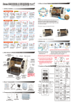
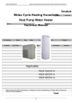
OWNER’ S MANUAL WIRE CONTROLLER OF AIR CONDITIONER MODEL: KJR-12B/DP(T)-E KJR-12B/DP(T)-E(C) KJR-12B/DP(T)-E(H) KJR-12B/DPC(T)-E KJR-12B/DP(T)-F RCW8(P/N:7ACEL1706) Thank you very much for purchasing our product. Before using your unit, please read this manual carefully and keep it for future reference. ● This manual gives detailed description of the precautions that should be brought to your attention during operation. ● In order to ensure correct service of the wired controller please read this manual carefully before using the unit. ● For convenience of future reference, keep this manual after reading it. ● The wired controller will reset to factory setting with auto mode, auto fan and 24°C(76°F) setting temperature when the air conditioner restarts after power failure. And this may cause inconsistent displays on the wired controller and on the air conditioner. You need to readjust the running status through the wired controller. CONTENTS 1. SAFETY PRECAUTION.............................................................................. 1 2. SUMMARIZE............................................................................................... 2 3. FUNCTION SUMMARY............................................................................... 2 4. NAME AND FUNCTION OF INDICATORS ON THE WIRE CONTROLLER............................................................................................ 3 5. INSTALLATION METHOD........................................................................... 4 6. NAME AND OPERATION OF THE BUTTON ON THE WIRE CONTROLLER.............................................................................................................. 5 7. USING METHOD ........................................................................................ 8 AUTOMATIC OPERATION......................................................................... 8 COOLING/HEATING/FAN ONLY OPERATION.......................................... 8 DRY OPERATION....................................................................................... 9 TIMER SETTING........................................................................................ 9 TIMER ON AND TIMER OFF BOTH........................................................... 9 CHANGE TIMER........................................................................................10 8.TECHNICAL INDICATION AND REQUIREMENT .....................................10 1. SAFETY PRECAUTIONS The following contents are stated on the product and the operation manual, including usage, precautions against personal harm and property loss, and the methods of using the product correctly and safely. After fully understanding the following contents (identifiers and icons), read the text body and observe the following rules. Identifier description Identifier Meaning Warning Means improper handling may lead to personal death or severe injury. Caution Means improper handling may lead to personal injury or property loss. [Note]: 1. “Harm” means injury, burn and electric shock which need long-term treatment but need no hospitalization 2. “Property loss” means loss of properties and materials. Icon description lcon Meaning It indicates forbidding. The forbidden subject-matter is indicated in the icon or by images or characters aside. It indicates compulsory implementation. The compulsory subject-matter is indicated in the icon or by images or characters aside. 1 Warning Warning Delegate installation Please entrust the distributor or professionals to install the unit. The installers must have the relevant know-how. Improper installation performed by the user without perm ission may cause fire, electric,shock, personal injury or water leakage. Forbid Do not spray flammable aerosol to the wire controller directly. Otherwise, fire may occur. Forbid Do not operate with wet hands or let water enter the wire controller. Otherwise, electric shock may occur. 2. SUMMARIZE 3. FUNCTION SUMMARY Usage Warning arning Usage condition: Main function: 1. Power supply: 5V DC. 2. Operation temperature: -15°C(-5°F)~ +43°C(+109°F). 3. Operation humidity: 40%-90%, RH. 1. Connecting to indoor unit by A, B, C, D, E termina.; 2. Button setting action mode. 3. LCD display. 4. Timer for rest time. 2 4. NAME AND FUCTION OF INDICATORS ON THE CONTROLLER 1 Operation mode indication 3 Follow me function 4 ON/OFF indication 1 5 Fan speed indication 2 1 2 Timer ON/OFF 12 6 Lock 7 Temperature display zone ① Operation mode indication: When press " MODE " button, the following mode can be selected in circle. Auto →Cool →Dry→Heat→Fan only→Auto. For cooling only model,heat mode is skipped. ② Timer : When adjust setting on time or only on time is set, the "ON" is lighted. When adjust setting off time or only off time is set , the "OFF" is lighted. If on and off timer are both set, the"ON" and "OFF"are both lighted. ③ Follow me function: There is a temperature sensor inside the wire controller, after setting temperature, it will compare the two temperatures, and the space of wire controller will be 3 the same as setting temperature. It is available under cooling, heating, auto mode. ④ ON/OFF indication : When it is on, the icon display, otherwise it is extinguished. ⑤ Fan speed indication : There are four fan modes : low, middle, high, auto. For some models, no middle fan then the middle fan is seen as high speed. ⑥ Lock: When the " LOCK " button is pressed, the icon appear and other buttons is unable, press again, the icon disappear. ⑦ Temperature display zone: Generally it displays setting temperature, it can be adjusted by press temperature button ▲ and ▼. But in fan mode, no display here. 5. INSTALLATION METHOD Emitter tube Wire Controller 5-way terminal +5V 5-Core Shield Cable GND RUN Indoor switch board Indoor Unit 4 When a wire controller is needed, a small 5-way terminal should be added,fix an infrared emitter with gumwater near the receiver on the switch board. Connect its anode and cathode to A and B,and +5V, GND, RUN to C, D, E on the switch board. 6. NAME AND OPERATION OF THE BUTTON ON THE WIRE CONTROLLER ⑦ MODE BUTTON ① TIMER ON BUTTON ② TIMER OFF BUTTON ③ FOLLOW ME BUTTON ④ ELECTRICAL HEATER BUTTON ⑤ RESET BUTTON ⑥ TIMER ON FOLLOW ME TIMER OFF AUXIL HEATER ON / OFF BUTTON ⑧ ADJUST BUTTON ▲ ⑨ ADJUST BUTTON ▼ ECO FAN SPEED MODE RESET SWING TEMP ⑩ SWING BUTTON 11 ECONOMY BUTTON 12 FAN SPEED BUTTON 13 LOCK BUTTON LOCK 5 ⑦ MODE BUTTON ① TIMER ON BUTTON ② TIMER OFF BUTTON ③ TIMER ON I-FEEL I-FEEL BUTTON ④ TIMER OFF HEATER ⑧ ADJUST BUTTON ▲ ⑨ ADJUST BUTTON ▼ SLEEP FAN SPEED MODE SWING TEMP ⑩ HEATER BUTTON RESET BUTTON ⑤ ON / OFF BUTTON RESET SWING BUTTON LOCK 11 SLEEP BUTTON 12 FAN SPEED BUTTON ⑥ 13 LOCK BUTTON NOTE All the pictures in this manual are for explanation purpose only. There may be slightly different from the wire controller you purchased(depend on model). The actual shape shall prevail. 6 ① Mode botton: When press this botton,the operation mode change as the following sequence: →AUTO → COOL→DRY→HEAT→FAN Remark: For the cooling only model, the heating mode is skipped. ② Timer on button : Press this button, timer on function is active. Then every press, the time increase 0.5h, after 10h, 1h increasement after each press. If cancel this Function,just set it to "0.0" . ③ Timer off button: Press this button, timer off function is active.Then every press, the time increase 0.5h, after 10h, 1h increasement after each press. If cancel this function, just set it to "0.0" . ④ Follow me button / I-FEEL button: When under cool, heat and auto mode, press this button, follow me function is active. Press again, this function is ineffective. ⑤Electrical heater button/Heater button : If press this button in heat mode, electrical heater function become ineffective. ⑥ Reset button(hidden): Use a 1mm stick to press in the little hole , then the current setting is canceled . The wire controller enter into original state. ⑦ON/OFF button: When in off state, press this button, the indicator is on, the wire controller enter into on state, and send setting information to in door Pcb. When in on state,press this button, the indicator is off, and send instruction. If timer on or timer off has been set, it concel this setting then send instruction to stop the machine. ⑧ Adjust button ▲: Set indoor temperature up. If press and hold on, it will increase at 1°C(2°F) per 0.5 second. ⑨ Adjust button ▼ : Set indoor temperature down . if press and hold on,it will decrease at 1°C(2°F) per 0.5 second. 7 ⑩ Swing button: First press, start swing function;second press, stop swing. (Match to some model with swing function). 11 Economy operation button / Sleep button: press this button, the indoor unit operates in economy mode, press again, exit this mode (it may be ineffective for some models) 12 Fan speed button: press this button consecutively, the fan speed will circle as follow: Lock button(hidden): When you push the LOCK button, all current settings are locked in and the wire controller does not accept any operation except that of the LOCK button. Use the lock mode when you want to prevent setting from being changed accidentally or play fully. Push the LOCK button again when you want to cancel the LOCK mode. 13 8 7. USING METHOD AUTOMATIC OPERATION Connect to power,indoor operation lamp flash. 1. Press "MODE" button, select " AUTO "; 2. Press the button "▲" and "▼", set temperature you want, generally it is among 17°C(62°F)~30°C(88°F); 3. Press " ON/OFF" button, operation lamp is on, the air-conditioner work in auto mode, indoor fan is auto, and can not be changed. Auto is displayed on LCD. Press ON/OFF button again to stop. 4. Economy operation is valid in auto mode. COOL/HEAT/FAN MODE OPERATION 1. Press "MODE" button, select "COOL" , "HEAT" or "FAN ONLY" mode. 2. Press temperature adjust button to select setting temp.. 3. Press "FAN SPEED" button to select high/mid/low/auto. 4. Press "ON/OFF" button, indoor unit operation lamp on, it works in selected mode. Press "ON/OFF" button again, it stops to work. Remark: When in fan mode, no temperature can be set. 1. Press " MODE " button, select " DRY " mode. 2. Press temperature adjust button to select setting temp. 3. Press " ON/OFF " button, indoor unit operation lamp on, it works in dry mode. Press ON/OFF button again, it stops to work. 4. In dry mode, economy operation and fan speed are ineffective. 2. Press " timer " on button repeatedly to adjust time setting. 3. If press this button and hold on, the time will increase at 0.5h, after 10h, it increase at 1h. 4. After setting 0.5 second, the wire controller send timer on information, it is finished. Timer off only: 1. Press "TIME OFF " button, it display "SET" on LCD, and display " H " and ON, it is waiting for timer on setting. 2. Press "TIME OFF" button repeatedly to adjust time setting. 3. If press this button and hold on , the time will increase at 0.5h, after 10h, it increase at 1h. 4. After setting 0.5 second, the wire controller send timer off information, it is finished. TIMER SETTING TIMER ON AND TIMER OFF BOTH Timer on only: 1. Press " TIME ON " button, it display "SET" on LCD, and display " H " and "ON" , it is waiting for timer on setting. 1. Set timer on time corresponding step1 and 2. 2. Set timer off time corresponding step1 and 2. DRY OPERATION as the as the 9 3. Timer off time must be longer than timer on time. 4. 0.5 second after setting, the wire controller send information.the setting is finished. EMC and EMI comply with the CE certification requirements. CHANGE TIMER If there is a need of changing timer time, press corresponding button to revise it. If concel timer, change timer time to 0.0. NOTE The timer time is relative time,that is delay after setting time( i, e: setting time is 8:05 A,M). So when imer is set, the standard time can not be adjusted. 10 8. TECHNICAL INDICATION AND REQUIREMENT Version: MDV06U-002HW 202000100068