1
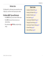
Fishfinder 400C owner’s manual © 2006, 2007 Garmin Ltd. or its subsidiaries Garmin International, Inc. 1200 East 151st Street, Olathe, Kansas 66062, USA Tel. (913) 397.8200 or (800) 800.1020 Fax (913) 397.8282 Garmin (Europe) Ltd. Liberty House Hounsdown Business Park, Southampton, Hampshire, SO40 9RB UK Tel.+44 (0) 870.8501241 (outside the UK) 0808 2380000 (within the UK) Fax+44 (0) 870.8501251 Garmin Corporation No. 68, Jangshu 2nd Road, Shijr, Taipei County, Taiwan Tel. 886/2.2642.9199 Fax 886/2.2642.9099 All rights reserved. Except as expressly provided herein, no part of this manual may be reproduced, copied, transmitted, disseminated, downloaded or stored in any storage medium, for any purpose without the express prior written consent of Garmin. Garmin hereby grants permission to download a single copy of this manual onto a hard drive or other electronic storage medium to be viewed and to print one copy of this manual or of any revision hereto, provided that such electronic or printed copy of this manual must contain the complete text of this copyright notice and provided further that any unauthorized commercial distribution of this manual or any revision hereto is strictly prohibited. Information in this document is subject to change without notice. Garmin reserves the right to change or improve its products and to make changes in the content without obligation to notify any person or organization of such changes or improvements. Visit the Garmin Web site (www.garmin.com) for current updates and supplemental information concerning the use and operation of this and other Garmin products. Garmin®, CANetTM, See-Thru®, and UltrascrollTM are registered trademarks or trademarks of Garmin Ltd. or its subsidiaries and may not be used without the express permission of Garmin. March 2007 Part Number 190-00757-00 Rev. C Printed in Taiwan Introduction Introduction The Fishfinder 400C is a full-featured, color sonar that offers a choice of display styles, a dual beam or dual frequency option, and more. Fishfinder 400C Tips and Shortcuts • Press HOME from any screen to return to the Home screen. • Press MENU from any of the main screens to access advanced settings. • Press and release the POWER key to adjust the display settings. Quick Links • • • • • • • • • Installing the Fishfinder 400C: page 1 Mounting the Fishfinder 400C: page 2 Installing the Transducer: page 4 Basic Operation: page 15 Customizing the Fishfinder 400C: page 21 Changing the System Settings: page 23 Customizing the Transducer Settings: page 23 Advanced Settings: page 25 Alarms and Messages: page 28 Fishfinder 400C Owner’s Manual Introduction Table of Contents Introduction............................................................................i Fishfinder 400C Tips and Shortcuts........................................ i Quick Links................................................................................ i Product Registration............................................................... iii Caring for the Fishfinder 400C............................................... iii Warnings.................................................................................. iv Important Information............................................................. iv Installing the Fishfinder 400C.............................................1 Step 1: Select a Location for the Fishfinder.......................... 1 Step 2: Mount the Fishfinder................................................... 2 Step 3: Install the Transducer................................................. 4 Step 4: Install the Wiring Harness........................................ 10 Step 5: Test the Installation................................................... 13 Basic Operation..................................................................15 Turning the Fishfinder 400C On or Off................................. 15 Adjusting the Backlight Setting............................................ 15 Using Simulator Mode........................................................... 15 Using the Fishfinder 400C Keypad....................................... 15 Understanding the Home Screen.......................................... 16 Understanding the Full Screen............................................. 17 Understanding the Split Zoom Screen................................. 17 Understanding the Flasher Screen....................................... 18 Understanding the Split Freq Screen................................... 18 ii Understanding the Numbers Screen.................................... 19 Understanding the Temp Log Screen................................... 19 Understanding the Configure Screen................................... 20 Customizing the Fishfinder 400C......................................21 Setting Alarms........................................................................ 21 Changing the Display Settings............................................. 21 Changing the Sonar Settings................................................ 22 Changing the System Settings............................................. 23 Configuring Transducer Settings......................................... 23 Customizing Units of Measure.............................................. 24 Advanced Settings.............................................................25 Resetting the Odometer......................................................... 26 Setting the Temp Log Duration and Scale........................... 26 Appendix.............................................................................27 Specifications......................................................................... 27 Optional Accessories............................................................. 27 Alarms and Messages............................................................ 28 Limited Warranty.................................................................... 29 Declaration of Conformity (DoC).......................................... 30 Software License Agreement................................................ 30 Index....................................................................................31 Fishfinder 400C Owner’s Manual Introduction Product Registration Caring for the Fishfinder 400C Use this area to record the serial number (8-digit number located on the back of the Fishfinder 400C) in case your Fishfinder 400C needs service. Keep the original sales receipt, or a photocopy, in a safe place. Cleaning the Case Help us better support you by completing our online registration today! Connect to our Web site at www.garmin.com/registration/. Serial Number: ___ ___ ___ ___ ___ ___ ___ __ Contact Garmin Contact Garmin if you have any questions while using your Fishfinder 400C. In the USA contact Garmin Product Support by phone: (913) 397-8200 or (800) 800-1020, Monday–Friday, 8 AM–5 PM Central Time; or go to www.garmin.com/support/, and click Product Support. In Europe, contact Garmin (Europe) Ltd. at +44 (0) 870.8501241 (outside the UK) or 0808 2380000 (within the UK). Tell Us What You Think Tell us how you like this manual! Fill out the Product Documentation Survey. Go to www.garmin.com/contactUs/, and click Product Documentation Survey. Fishfinder 400C Owner’s Manual The case is constructed of high-quality materials and does not require user maintenance, except cleaning. Clean the unit’s outer casing (except for the screen) using a cloth dampened with a mild detergent solution and then wipe dry. Avoid chemical cleaners and solvents that may damage plastic components. Cleaning the Screen The unit’s lens is coated with a special anti-reflective coating that is sensitive to skin oils, waxes and abrasive cleaners. Cleaners containing ammonia, alcohol, abrasives, or anti-grease detergents will harm the anti-reflective coating. It is important to clean the lens using an eyeglass lens cleaner (that is specified as safe for antireflective coatings) and a clean, lint-free cloth. Water Immersion The unit is waterproof to IEC Standard 60529 IPX7. It can withstand immersion in 1 meter of water for 30 minutes. Prolonged submersion can cause damage to the unit. After submersion, be certain to wipe and air dry the unit before reuse. iii Introduction Warnings Failure to avoid the following potentially hazardous situations could result in an accident or collision resulting in death or serious injury. • When navigating, carefully compare information displayed on the unit to all available navigation sources, including information from visual sightings, and maps. For safety, always resolve any discrepancies or questions before continuing navigation. WARNING: This product, its packaging, and its components contain chemicals known to the State of California to cause cancer, birth defects, or reproductive harm. This Notice is provided in accordance with California’s Proposition 65. See www.garmin.com/prop65 for more information. Hg - lampS inside this product contain mercury and must be recycled or disposed of according to local, state, or federal laws. For more information go to: www.garmin.com/aboutGarmin/environment/disposal.jsp. Important Information The California Waste Recycling Act of 2003 requires the recycling of certain electronics. For more information on the applicability to this product, see www.erecycle.org. iv Fishfinder 400C Owner’s Manual Installing the Fishfinder 400C Installing the Fishfinder 400C To successfully operate your Fishfinder 400C, you must properly install the fishfinder and all of its related parts. Compare the contents of this package with the packing list on the box. If any pieces are missing, contact your Garmin dealer immediately. Before you begin the installation: • Read and follow the instructions to install the unit. • Gather the appropriate fasteners and tools. • Verify that all cables can reach the unit mounting location and the transducer. • Wear safety goggles and a dust mask when drilling, cutting, or sanding. If you experience difficulty installing the unit, contact Garmin Product Support or contact a professional installer. To install and use your fishfinder: 1 2. 3. 4. 5. Select a location for the fishfinder. Mount the fishfinder. Install the transducer. Install the wiring harness. Test the installation. Fishfinder 400C Owner’s Manual Step 1: Select a Location for the Fishfinder Consider the following when you select an installation location: • Provides optimal viewing as you operate your vessel. • Allows easy access to the unit’s keypad. • Is strong enough to support the weight of the fishfinder and protect it from excessive vibration or shock. • Allows room for the routing and connection of the power/data and transducer cables. There should be at least a 3-inch (8 cm) clearance behind the case. DO NOT mount the unit in an area that is exposed to extreme temperature conditions. NOTE: The temperature range for the Fishfinder 400C is 5°F to 131°F (-15°C to 55°C). Extended exposure to temperatures exceeding this range (in storage or operating conditions) may cause failure of the LCD screen. This type of failure and related consequences are NOT covered by the manufacturer’s limited warranty. Installing the Fishfinder 400C Step 2: Mount the Fishfinder You can mount your fishfinder in one of two ways: • Surface Mount—mount the fishfinder onto a bracket (included) that attaches to the console or overhead. • Flush Mount—use the optional flush mount kit to mount the fishfinder into a flat panel. See the “Appendix” for more information. Surface Mounting the Fishfinder The Fishfinder 400C’s compact, waterproof case is suitable for mounting in exposed locations or at the nav station. The Fishfinder 400C comes with a tilt/swivel mounting bracket that can be used for console or overhead mounting. Mounting the Bracket Assembly Tools (not included)—drill, screwdriver (Phillips or standard), and one of the following: • Three #8 (4 mm) pan-head machine bolts with matching nuts and washers and a 5/32" (5 mm) drill bit. • Three #8 pan-head self-tapping screws and a 1/16" drill bit for drilling starter holes. Use a pan-head machine bolt or self-tapping screw to secure the swivel base. If you use a screw with a countersunk head, you risk damaging the mounting bracket. OK Fishfinder 400C Owner’s Manual Installing the Fishfinder 400C To mount the bracket assembly: 1. Using the swivel base as a template, mark the location of the three holes that secure the bracket to the mounting surface. 2. Drill the mounting holes. • If you secure the base with machine bolts, drill three 5/32" (5 mm) holes at the locations you marked. OR • If you secure the base with self-tapping screws, drill starter holes at the locations you marked. Do not make the starter holes deeper than half the screw length. 3. Secure the swivel base with three bolts or screws. DO NOT OVERTIGHTEN. 4. Place the swivel mount bracket over the swivel base and secure it with the short knob. Fishfinder 400C Owner’s Manual Installing the Fishfinder 400C on the Mounting Bracket To install the unit on the mounting bracket: 1. Align the slot on the back of the fishfinder with the long mounting knob, and slide the fishfinder into place. If necessary, adjust the long knob to spread the bracket arms apart. (Turn counter-clockwise to widen the bracket arms and clockwise to tighten.) 2. Adjust the fishfinder angle, and tighten the long mounting knob until snug. 3. Rotate the swivel mount bracket by twisting it left or right. The bracket clicks as you turn it. Select a good viewing angle, and then tighten all knobs. 4. Connect the power/data and transducer cables to the back of the fishfinder, making sure the locking rings are fully tightened on both connectors. Installing the Fishfinder 400C Step 3: Install the Transducer Proper transducer installation is key to getting the best performance from your fishfinder. If the transducer lead is too short, extension cables are available from your Garmin dealer. Coil and secure any excess cable. CAUTION: DO NOT cut the transducer lead or any part of the transducer cable, because cutting the transducer cable voids your warranty. The cable cannot be spliced and connected to any existing (Garmin or non-Garmin) transducer cables. The following pages contain tips and basic installation instructions for some popular transducers. Detailed installation instructions are provided in the transducer kits. Some transducers might have to be installed by a professional marine installer. Assembling the Transducer To ������������������������� assemble the transducer: 1. Insert the rubber washer and plastic spacer into the transducer at the same time. DO NOT lubricate the rubber washer. 2. Route the cable toward the back of the transducer. Slide the transducer into the transducer mount. 3. Place a 5 mm flat washer on the 10-32 x 1.75" screw, and insert the screw through the transducer mount, spacer, and rubber washer. 4. Place the remaining 5 mm flat washer on the exposed end. Install the 10-32 lock nut finger tight. You can tighten the transducer further after installation on the boat. Cable tie slot Back of the transducer Fishfinder 400C Owner’s Manual Installing the Fishfinder 400C Mounting the Transducer on a Trolling Motor (Dual Beam Transducers Only) To mount the transducer on a trolling motor: 1. Slide the large cable tie through the slot on the transducer mount with the ridges of the band facing up until equal lengths extend on both sides of the mount. note: For cold water, or heavy timber or debris areas, a metal 4-5" worm gear clamp is recommended. 2. Position the mount gasket on the curved top of the transducer mount. 3. Place the transducer assembly against the motor body of the trolling motor, with the front of the transducer pointed away from the trolling motor propeller. 4. Wrap the two ends of the cable tie around the motor body. Place the pointed end of the cable tie through the fastener hole on the opposite end and pull it through until it is snug but not tight. (The cable tie clicks when you pull it.) 5. Position the transducer so that it is parallel with the bottom when in use, and make sure the gasket is aligned properly. Pull the cable tie end until tight. Trim off the excess if necessary. Tighten the 10-32 locking nut until it touches the mounting bracket, and then tighten 1/4 turn more. (Do not overtighten.) Fishfinder 400C Owner’s Manual 6. Route the 30-foot (9 m) transducer cable using the supplied cable ties to secure the cable to the motor shaft. You can fill the forward-facing portion (except the cable tie pocket) of the transducer mount with sealant to avoid accumulating debris. Cable tie Front of the transducer Installing the Fishfinder 400C Mounting the Transducer on a Transom 533*AYHAWK !PPLYMARINESEALANTTOALL SCREWTHREADSTOPREVENTWATER FROMSEEPINGINTOTHETRANSOM -OUNTTHETRANSDUCERCABLE COVERWELLABOVETHE WATERLINE 4RANSDUCERSHOULDEXTEND BELOWFIBERGLASSHULLOR BELOWALUMINUMHULL /+ -OUNTTHETRANSDUCERPARALLELWITHTHEBOTTOM -AKESURETHATTHETRANSDUCERISBELOW WATERLEVELWHENTHEBOATISONPLANE ATHIGHSPEED $ONOTMOUNTTHETRANSDUCERDIRECTLYINTHE PATHOFTHEPROP4HETRANSDUCERCANCAUSE CAVITATIONTHATMAYDEGRADETHEBOATS PERFORMANCEANDDAMAGETHEPROP Fishfinder 400C Owner’s Manual Installing the Fishfinder 400C When selecting a transom mount location, consider the following for optimal performance: • For your sonar to operate properly, the transducer must be located in calm water. DO NOT mount the transducer behind strakes, rivet lines, struts, fittings, water intake, discharge ports, eroding paint, or anything that creates turbulence. • Mount the transducer as close to the center of the boat as possible. • DO NOT cut the transducer lead. (This voids your warranty.) • DO NOT mount the transducer in locations where it might be jarred when launching, hauling, trailering, or storing. • DO NOT mount the transducer in the path of the prop on single-drive boats. The transducer can cause cavitation that can degrade the boat’s performance and damage the prop. On twin-drive boats, mount the transducer between the drives, if possible. NOTE: DO NOT mount the transducer behind strakes, struts, fittings, water intake or discharge ports, or anything that creates air bubbles or causes the water to become turbulent. The transducer must be in clean (non-turbulent) water for optimal performance. Fishfinder 400C Owner’s Manual Tool List (not included)—drill, 3/8" wrench or socket, 5/32" and 1/8" drill bits, masking tape, #2 Phillips screwdriver, and marine sealant. To mount the transducer on a transom: 1. Position the transducer mount at the selected transom location. Make sure the transducer is parallel with the water line. Mark the center locations of each hole on the transducer mount. 2. Using a 5/32" bit, drill the pilot holes approximately 1" (25 mm) deep at the marked locations. To avoid drilling the holes too deep, wrap a piece of tape around the bit at 1" from the point of the bit. 3. Apply marine sealant to the 5 x 30 mm screws. Attach the transducer assembly to the transom using the 5 x 30 mm screws. Adjust the transducer assembly to extend beyond the bottom of the transom approximately 1/8" (3 mm) on fiberglass hulls or 3/8" (10 mm) on aluminum hulls. Adjust the transducer assembly to be aligned parallel with the water. 4. Tighten the 10-32 locking nut until it touches the mounting bracket, and then tighten 1/4 turn more. (Do not overtighten.) 5. Place the first cable clamp on the transducer cable approximately one third of the distance between the transducer and the top of the transom. Installing the Fishfinder 400C 6. Mark the location. Using a 1/8" bit, drill a pilot hole approximately 3/8" (10 mm) deep. 7. Attach the cable clamp using a 4 x 12 mm screw. Coat the screw with marine sealant before installation. Repeat steps 5 and 6 using the other cable clamp. 8. Route the transducer cable, as needed, to the fishfinder. DO NOT CUT THE CABLE. Avoid routing the cable with electrical wires or other sources of electrical interference. Drill pilot holes here. Vertical Bottom of To avoid drilling a hole to mount a thru-hull transducer, a transducer can be secured with epoxy inside a boat (shoot-thruhull installation). This type of installation can provide better noise reduction and allow you to use a higher Gain setting. For a transducer to be mounted inside the hull (shoot-thru, not thruhull), the boat must be fiberglass, with no core. Contact your boat manufacturer if you are unsure. Professional installation might be necessary. Some transducers are specifically designed to be mounted inside a fiberglass hull. The standard plastic transom mount transducer can also be mounted using this method. If using a temperature sensing transducer, the temperature shown reflects the hull temperature. Level Align with the transom bottom. The transducer should extend 1/8" below fiberglass hulls or 3/8" below aluminum hulls. Shoot-Thru-Hull Installation m the transo Keep it parallel with the water line. OK Fishfinder 400C Owner’s Manual Installing the Fishfinder 400C Selecting a Location for a Shoot-Thru-Hull Installation When installing a transducer, the installation location must be the following: • Solid fiberglass, without any air bubbles, laminates, fillers, or dead air space. • In an area of clean (non-turbulent) water at all speeds. • The location must not be over any strakes or behind any obstruction on the hull that would create turbulence. NOTE: Many modern hulls have a dedicated pocket for shoot-thru-hull transducer installation. If you are unsure if your hull is equipped with a pre-located pocket, contact your hull manufacturer. To test the location: 1. Fabricate a test device from a section of PVC pipe or a can, as shown in the following illustration. 2. Temporarily seal the test device to the hull with caulking or RTV sealer, and fill with water or light mineral oil. 3. Place the transducer in the water, pointed directly at the bottom and weight it down. Set the unit for optimum performance. If the sonar performance is significantly degraded, another location must be tested. Fishfinder 400C Owner’s Manual PVC pipe or a can Strip caulk or RTV sealer Weight the transducer to hold it in place. Fill a pipe or can with water or a light mineral oil. Hull surface Testing the Location To permanently install the transducer: 1. Lightly sand the surface of the hull and face of the transducer with 400 grit wet or dry sandpaper. 2. Build a dam using strip caulk about 1/4" (6 mm) tall. Pour about 1/8" (3 mm) of two-part, slow-cure epoxy into the dam. 3. Place the transducer in the epoxy, turning the transducer to work out any air bubbles. 4. Weight the transducer in place, and allow it to cure for 24 hours. Installing the Fishfinder 400C Step 4: Install the Wiring Harness The Fishfinder 400C comes with a wiring harness that connects the fishfinder to power and the transducer with one easy-to-remove connection and provides interface capabilities for connecting external devices. The color code in the diagram (see ��page 11) indicates the appropriate harness connections. The replacement fuse is a AGC/ 3AG - 3 Amp fuse. If it is necessary to extend the power wires, use 22 AWG wire. DO NOT cut the transducer cable, because this voids your warranty. If your boat has an electrical system, you might be able to wire the fishfinder directly to an unused holder on your current fuse block. If you are using the boat’s fuse block, remove the in-line fuse holder supplied with the fishfinder. You can also wire the fishfinder directly to the battery. Note: During a typical installation, use only the Red and Black wires. The other wires do not have to be connected for normal operation of the Fishfinder 400C unit. For information on connecting to a NMEA or CANet compatible device, see page 12. 3-Amp fuse To 10-38 Volt boat supply 2A Boat ground + Caution: The Fishfinder 400C maximum input voltage is 35 Volts DC. Do not exceed this voltage, because this can damage the Fishfinder 400C and void the warranty. 1. Use a test light or voltmeter to determine the polarity of the voltage source. 2. Connect the Red (+ or positive) wire to the positive voltage terminal. (If you use the boat’s fuse block, route the positive connection through the fuse, as shown on the diagram.) 3. Connect the Black (- or ground) wire to the negative voltage terminal. 4. Install or check the 3-Amp fuse (on the boat’s fuse block or in the in-line holder). 5. Align the notches on the cable plug and on the back of the fishfinder. Insert the cable into the connector, and turn the lock ring counter-clockwise until it stops. - To install the wiring harness: — + To Fishfinder 400C Fuse block 10 Fishfinder 400C Owner’s Manual Installing the Fishfinder 400C PIN 8 - Black (Ground) PIN 13 - Red (DC Positive) PIN 7 - Yellow (Alarm) PIN 12 - White (CANet H) PIN 16 - Green (CANet L) PIN 18 - Blue (NMEA Out) DC Power Source Fishfinder 400C Pin Assignment CANet L CANet H Fishfinder 400C Wiring Harness Fishfinder 400C Owner’s Manual11 Installing the Fishfinder 400C Connecting to a NMEA device You can connect the Fishfinder 400C to another piece of NMEA compatible electronic equipment, such as a Garmin GPS (Global Positioning System) device. If equipped with a capable transducer, the Fishfinder 400C can send depth, temperature, and speed information. Refer to the wiring diagrams on page 11 for connecting the Fishfinder 400C to NMEA compatible devices. To install the wiring harness to a GPS or other NMEA device: 1. Follow the voltage source installation steps (see page 10). For Garmin units, the ground (Black) wires serve as NMEA ground and must be attached together or on the same terminal. Refer to the wiring diagram of your GPS unit for wire identification. 2. Connect the Blue (NMEA Out) wire from the Fishfinder 400C to the NMEA In wire on the GPS/NMEA unit’s wiring harness. 3. Turn on the Fishfinder 400C NMEA Output setting (page 23). For Garmin GPS units, set the communications interface to NMEA/NMEA, NMEA In/NMEA Out, or NMEA. Interfacing with NMEA The Fishfinder 400C allows for NMEA 0183, Version 3.01 output with a compatible GPS or navigation device. You must set NMEA Output On to send data (page 23). 12 The SDDBT, SDDPT, SDMTW, SDVHW, SDWPL sentences are sent in NMEA 0183, Version 3.01 output from the Fishfinder 400C. You can purchase complete information about National Marine Electronics Association (NMEA) format and sentences from: NMEA Seven Riggs Avenue Severna Park, MD 21146 USA www.nmea.org Installing the Fishfinder 400C to a Garmin CANet The Fishfinder 400C is a CANet-compatible sonar device. Using the CANet (if applicable) optimizes the performance of CANet-compatible units, allowing sonar information from the Fishfinder 400C to be shared with up to two CANet compatible Garmin GPS units. A standard NMEA connection only allows depth, temperature, and speed information to be sent to a single GPS device, whereas a CANet connection provides full sonar readings, including Ultrascroll™, so you can view and control the same information on your compatible GPS unit(s) as you can on your Fishfinder 400C. Note: To use the Garmin CANet with your Fishfinder 400C, you must obtain a CANet Kit. Contact your Garmin dealer, or visit www.garmin.com. Fishfinder 400C Owner’s Manual Installing the Fishfinder 400C Step 5: Test the Installation To turn on your Fishfinder 400C for the first time, press and hold the POWER key until the unit beeps and turns on. Use the ROCKER and the SELECT key and follow the screens to configure your Fishfinder 400C. Note: Although it is possible to perform some checks with the boat trailered, the boat should be in the water to properly test the installation. To configure your Fishfinder 400C for the first time: Select a language. Select a transducer type. Select units of measure. Select a color scheme. The Home screen appears after you select your configuration options. After 15 seconds of inactivity, the fishfinder automatically switches to Full Screen. Note: If the transducer is not detected, a “Transducer Disconnected, Sonar Turned Off” message appears. Fishfinder 400C Owner’s Manual13 Installing the Fishfinder 400C Because water is necessary to carry the sounder’s sonar signal, the transducer must be in the water to work properly. You cannot get a depth or distance reading when out of the water. When you place your boat in the water check for leaks around any screw holes that were added below the water line. DO NOT leave your boat in the water for an extended period of time without checking for leaks. To test the transom mount transducer installation: 1. Begin testing the installation at a slow speed. If the sonar appears to be working properly, gradually increase the boat’s speed while observing the sonar’s operation. If the sonar signal is suddenly lost or the bottom return is severely degraded, note the speed at which this occurs. 2. Return the boat to the speed at which the signal was lost. Make moderate turns in both directions, and see if the signal improves. 14 3. If the signal strength improves while turning, adjust the transducer so that it extends another 1/8" below the transom of the boat. It might take several adjustments to eliminate the degradation. 4. If the signal does not improve, you might have to move the transducer to a different location. NOTE: When adjusting the depth of the transducer, make the adjustments in small increments. Placing the transducer too deep can adversely affect the boat’s performance and put the transducer at greater risk of striking underwater objects. Fishfinder 400C Owner’s Manual Basic Operation Basic Operation Using the Fishfinder 400C Keypad Turning the Fishfinder 400C On or Off Power/ Backlight Range (-/+) Press and hold the POWER key until the unit beeps and the Home screen appears. Note: When you turn on the Fishfinder 400C for the first time, you have to select a language, transducer type, units of measure, and color scheme. ROCKER SELECT HOME MENU MENU Adjusting the Backlight Setting 1. Press and release the POWER key. 2. Press left on the ROCKER to decrease the brightness; press right to increase. Using Simulator Mode If a transducer is not connected, no data is shown on the screens. By turning on Simulator Mode, the Fishfinder 400C acts as though a transducer is connected. Use Simulator Mode to practice and learn how to use your Fishfinder 400C. Caution: When in Simulator Mode, the depth, temperature, and speed information are simulated. They do not represent the actual depth, water temperature, or vessel speed. SELECT HOME POWER/BACKLIGHT—Press and hold to turn the unit on or off; press and release to adjust the backlight and day/night modes. RANGE (-/+)—Press to adjust the range of the sonar. ROCKER—Press up, down, left, or right to move through menus, highlight fields, and enter data. SELECT—Press to select highlighted items and confirm onscreen messages. HOME—Press to return to the Home screen. MENU—Press to access additional settings and configuration options; Press to return to the previous screen when indicated. Fishfinder 400C Owner’s Manual15 Basic Operation Understanding the Home Screen When you turn on your Fishfinder 400C, the Home screen appears. Press up or down on the ROCKER, and then press SELECT to choose an option. note: Options on this screen vary based on the type of transducer installed. Full Screen Opens a full-screen graph of the transducer’s sonar readings (page 17). Flasher (Dual Beam transducer only) Opens a round flasher to indicate the transducer’s sonar readings as an alternative to the linear graph (page 18). Split Freq (Dual Frequency transducer only) Opens a split-screen that uses the full capability of the dual frequency transducer. A 50kHz frequency graph appears on the left; a 200kHz frequency graph appears on the right (page 18). Split Zoom Opens a split-screen with the normal graph on the right zoomed to your preferred level on the left (page 17). Numbers Opens a set of data fields to show information numerically (page 19). Temp Log Home Screen (Dual Beam) Home Screen (Dual Frequency) Shows a customizable graph of the water temperature when using a compatible transducer or sensor (page 19). Configure Configure unit settings (page 20). 16 Fishfinder 400C Owner’s Manual Basic Operation Understanding the Full Screen Understanding the Split Zoom Screen On the Home screen, highlight Full Screen, and press SELECT. On the Home screen, highlight Split Zoom Screen, and press SELECT. The Full Screen is the main screen for both dual beam and dual frequency transducers. Depth Temperature Use the Split Zoom screen to view the full sonar data from the graph as well as a zoomed in portion on the same screen. Depth, temperature, and speed Speed Suspended targets Range Zoomed depth scale Zoom window Transducer mode Bottom Range Transducer mode Fishfinder 400C Owner’s Manual17 Basic Operation Understanding the Flasher Screen The Flasher screen (dual beam transducer only) provides an almost instantaneous return of what is below your boat. The depth scale is organized as a ring that starts at the top, or 12:00, and progresses clockwise. Sonar information flashes on the ring when it is received at the depth indicated on the inside ring. Like the regular graph, The colors indicate different strengths of the sonar return. Understanding the Split Freq Screen Use the Split Freq screen (dual frequency transducer only) to view both the 50kHz and 200kHz frequencies on the same screen. On the Home screen, highlight Split Freq, and press SELECT. Depth, temperature and speed On the Home screen, highlight Flasher, and press SELECT. Voltage Water Temp Flasher ring Range Depth Water speed 18 Odometer Frequencies Fishfinder 400C Owner’s Manual Basic Operation Understanding the Numbers Screen Understanding the Temp Log Screen On the Home screen, highlight Numbers, and press SELECT. On the Home screen, highlight Temp Log, and press SELECT. The Numbers screen shows data fields populated by important numeric information instead of a graph. The data fields you see are determined by the capabilities of your transducer. If you are using a temperature-capable transducer, the Temp Log screen keeps a graphic log of temperature readings over time. The current temperature and depth are shown in the top left corner. Temp and depth Time elapsed All transducers show depth. If you are using a temperature-capable transducer, the Water Temp field appears. If you are using a speedcapable transducer, the Water Speed and Odometer fields appear. Temp range The temperature appears along the right side and the time elapsed appears along the bottom. The graph scrolls to the left as information is received. Fishfinder 400C Owner’s Manual19 Basic Operation Understanding the Configure Screen The Configure screen contains the main configuration options for the Fishfinder 400C. From this screen, you can define and adjust settings universal to all Fishfinder 400C screens. On the Home screen, highlight Configure, and press SELECT. Alarms—set alarms to alert you of various events. See page 21. Display—customize display settings including backlight and Day/ Night mode. See page 21. Sonar—customize sonar settings. See page 22. System—set various system options. See page 23. Transducer—set transducer options. See page 23. Units—customize the units of measure shown on Fishfinder 400C screens. See page 24. For more information on the Configure screen, see the “Customizing the Fishfinder 400C” section beginning on page 21. 20 Fishfinder 400C Owner’s Manual Customizing the Fishfinder 400C Customizing the Fishfinder 400C Setting Alarms You can set the Fishfinder 400C to sound an audible alarm when certain conditions are met. By default, all alarms are turned off. Changing the Display Settings You can switch between Day and Night modes and brighten or darken the backlight. To change the display settings, on the Configure screen, highlight Display, and press SELECT. To set an alarm, on the Configure screen, highlight Alarms, and press SELECT. Shallow Water/Deep Water—set an alarm to sound when the depth is less than or greater than the specified value. Fish—set an alarm to sound when the unit detects a suspended target of the specified symbols. Press left or right on the ROCKER to switch between Day and Night mode. Press left or right on the ROCKER to adjust the backlight Water Temp—set an alarm to sound when the transducer reports a temperature that is 2° F (1.1° C) above or below the specified temperature. Battery—set an alarm to sound when the battery reaches a userdetermined low voltage. Drift—set an alarm to sound when the depth changes by the value specified. Fishfinder 400C Owner’s Manual21 Customizing the Fishfinder 400C Changing the Sonar Settings To change the sonar settings, on the Configure screen, highlight Sonar, and press SELECT. Color Scheme—choose white or blue. This affects the background on all sonar screens, but does not change the Numbers or Temp Log screens. Fish Symbols—set how the Fishfinder 400C interprets suspended targets. The Fishfinder 400C does not interpret the sonar return data. (default) Suspended targets appear as symbols. Background sonar information appears, making the distinction between fish and structure easier. Suspended targets appear as symbols with background information shown. The target depth of each symbol is also indicated. Suspended targets appear as symbols. No background information appears. Suspended targets appear as symbols with no background information shown. The target depth of each symbol is indicated. 22 Scroll Speed—adjust the rate at which the sonar scrolls from right to left (Ultrascroll, Fast, Medium, or Slow). If you have a speed-capable transducer, select Auto to have the scroll speed automatically adjust to your vessel’s water speed. Surface Noise—show or hide the sonar returns near the surface of the water. Hide surface noise to help reduce clutter. Whiteline—highlights the strongest signal from the bottom to help identify its hardness or softness. • Off—(default) Whiteline is disabled. • High—the most sensitive setting. Almost all stronger returns are highlighted in white. • Medium—many stronger returns are highlighted in white. • Low—the least sensitive setting. Only the strongest returns are highlighted in white. Numbers—show or hide battery voltage, water temperature, or water speed (if your transducer is capable). Note: To show water temperature or water speed, change the setting to Auto. If the connected transducer is capable, the data is shown. Fishfinder 400C Owner’s Manual Customizing the Fishfinder 400C Changing the System Settings Configuring Transducer Settings Beeper—set when the unit makes audible sounds. The three settings are Off, Alarms Only (default), and On (keys and alarms). Type—select the transducer type (Dual Frequency or Dual Beam). To change the system settings, on the Configure screen, highlight System, and press SELECT. Simulator—turn on the Simulator to have the Fishfinder 400C act as though a transducer is connected. NMEA Output— connect the Fishfinder 400C to NMEA compatible electronic equipment (such as a Garmin GPS device) and send information. To do so, you must change this setting to On. For more information on connecting to a NMEA device, see page 12. Language—select the on-screen language. System Information—view the current operating software version and your unit’s unique internal unit ID. Factory Settings—reset the Fishfinder 400C to the factory settings. You are prompted to confirm your choice to restore all factory settings. Choose Yes. Otherwise, choose No to retain your current configuration. To change the transducer settings, on the Configure screen, highlight Transducer, and press SELECT. Keel Offset—offset the surface reading for the depth of a keel so you can measure depth from the bottom of your keel instead of from the transducer’s location. Enter a positive number to offset for a keel. You can enter a negative number to compensate for a large vessel that may draw several feet of water. Transducer at Surface Enter (+) positive number to show depth from the bottom of keel. Transducer at Bottom of Keel Enter (-) negative number to show depth from the surface. Fishfinder 400C Owner’s Manual23 Customizing the Fishfinder 400C To adjust the Keel Offset: 1. Highlight Keel Offset, and press SELECT. 2. Use the ROCKER to set the value of the keel offset. 3. Press SELECT to accept the number. Note: Press MENU to cancel your changes and return to the Transducer menu. Calibrate Water Speed—to use a speed sensing transducer, use this menu to calibrate the speed sensor. If you are not using a speed sensing transducer, this menu does not appear. To calibrate the speed sensor: 1. Highlight Calibrate Water Speed, and press SELECT. 2. Bring the boat to cruising speed. Note your top speed, and then stop the boat. 3. Highlight OK, and press SELECT. 24 Customizing Units of Measure To change the units of measure, on the Configure screen, highlight Units, and press SELECT. Depth—select Feet (ft), Meters (m), or Fathoms (fa). Water Temp—select Fahrenheit (°F) or Celsius (°C) (with a compatible transducer). Water Speed—select Miles/Hour (mh), Kilometers/Hour (kh), or Knots (kt) (with a compatible transducer). Distance—select Statute (mi), Metric (km), or Nautical (nm) (with a compatible transducer). Note: If the boat is not moving fast enough or the speed sensor is not registering a speed, a “Speed Too Low” message appears. Highlight OK, press SELECT, and safely increase boat speed. If you get the message again, stop the boat and make sure the speed sensor wheel is not stuck. If the wheel turns freely, check the cable connections. If you continue to get the message, contact Garmin Product Support. Fishfinder 400C Owner’s Manual Advanced Settings Advanced Settings Press MENU on any screen to access advanced options. Highlight Manual Gain, and press SELECT to manually adjust the Gain. To see more detail, increase the Gain. If there is too much detail, or the screen is cluttered, decrease the Gain. Beam—when using a Dual Beam transducer, select a wide or narrow beam. Frequency—when using a Dual Frequency transducer, select how the frequencies appear on screen. By default, the frequency is set to 200kHz. You can specify that the unit uses only the 200kHz frequency, the 50kHz frequency, or Dual Frequency. Note: If you choose Dual, the Split Freq screen appears. Zoom—zoom in to a section of the Full Screen. The zoom is off, or set to No Zoom by default. Four options are available: Dual Frequency Dual Beam Range—By default, the range is set to Auto. The range of the depth scale on the right side of the screen adjusts automatically as the depth readings increase or decrease. Highlight Manual Range and press SELECT to manually adjust the scope of the depth scale. • 2x Zoom—twice the magnification. • 4x Zoom—four times the magnification. • Bottom Lock—locks the zoom window to the bottom. The default zoom span is 10 ft, and can be adjusted. • Split Zoom—opens the Split Zoom screen. Gain—controls the sensitivity of the Fishfinder 400C’s sonar receiver. By default, the Gain is set to Auto, which automatically sets the sonar sensitivity. Fishfinder 400C Owner’s Manual25 Advanced Settings Zoom Depth (While Zoomed)—available only when you are using a 2x or a 4x Zoom. By default, the Zoom Depth is set to Auto and automatically adjusts with the depth. You can adjust this setting to zoom in at a specific depth. Span (While Zoomed with Bottom Lock)—While using Bottom Lock, this option replaces the Range option. Adjust this setting just as you would the Range setting to expand or contract the zoomed distance from the bottom. Depth Line—turn on the depth line to quickly reference a specific depth on the Full Screen, Split Zoom screen, or Split Freq screen. While viewing a screen showing the Depth Line, press up or down on the ROCKER to move the line. A-Scope (Dual Frequency Transducer)—vertical flasher that appears along the right side of the screen. The A-Scope indicates structure and bottom returns much like the Flasher screen (page 18). The horizontal width of a signal in the A-Scope indicates the strength of the signal. 26 Resetting the Odometer If you are using a speed sensing transducer, an odometer is available on the Numbers screen and the Flasher screen that tracks the distance you travel. To reset the odometer: 1. Press MENU. 2. Highlight Reset Odometer, and press SELECT. 3. Highlight Yes, and press SELECT. Setting the Temp Log Duration and Scale On Temp Log screen, press MENU to view advanced options. Duration—set the scope of time along the bottom of the graph. Scale—set the temperature span along the right side of the graph. Fishfinder 400C Owner’s Manual Appendix Appendix Specifications Optional Accessories You can purchase the following optional accessories on the Garmin Web site (www.garmin.com): Physical Specifications Flush Mount Kit—mounts your fishfinder flush on the bulkhead or cabin wall. Weight: 1.20 lbs (.544 kg) CANet™ Connection Kit—allows you to connect your Fishfinder 400C to CANet-capable Garmin chartplotters, so you can read sonar displays on chartplotters located elsewhere in the boat. Size: 5" H x 5.7" W x 3" D (12.7 cm x 14.5 cm x 7.62 cm) Display: 4.0" diagonal (10.19 cm), 3.21" H x 2.41" W (8.16 cm x 6.12 cm), QVGA display with adjustable brightness, 320 x 240 pixels, capable of 4,096 colors. Case: Fully gasketed, high-impact plastic alloy, waterproof to IEC 529 IPX7 standards. Temp. Range: 5ºF to 131ºF (-15ºC to 55º C) Power Source: 10-35 VDC Usage: 21 Watts max at 12 VDC Fuse: AGC/3AG - 3.0 Amp Sonar Power: Dual Frequency, 500 Watts (RMS), 4,000 Watts (peak to peak); Dual Beam, 400 Watts (RMS), 3,200 Watts (peak to peak) Frequency: 50/200 kHz (dual frequency), 80/200 kHz (dual beam) Depth: 1,500 ft (dual frequency), 900 ft (dual beam) (Depth capacity is dependent on water salinity, bottom type, and other water conditions.) Fishfinder 400C Owner’s Manual27 Appendix Alarms and Messages The Fishfinder 400C uses an on-screen message system to alert you to unit operating characteristics. When a message appears, press SELECT to acknowledge the message and return to the screen you were viewing. Battery Alarm—battery voltage has fallen below the value entered in the Battery Alarm setup. Battery Voltage Is Too High—too much input voltage; the unit shuts off in 10 seconds. Decrease the input voltage to 35 Volts or less. Boat Is Not Moving Fast Enough to Calibrate—the boat is not moving fast enough for the speed wheel to provide a valid speed. Can’t Read Voltages That High, Limited to Top of Range—the voltage value in the Battery Alarm setup is higher than the unit can read. Can’t Read Voltages That Low, Limited to Bottom of Range—the voltage value in the Battery Alarm setup is lower than the voltage where the unit automatically turns off. Deep Water Alarm—the Deep Water Alarm depth has been reached. 28 Drift Alarm—the depth has changed by the amount of the Drift Alarm value. Fish Alarm—an icon appears and a beep sounds (if enabled) when a fish is detected. This alarm does not show a message banner. Shallow Water Alarm—the Shallow Water Alarm depth has been reached. Simulating Operation—the unit is in Simulator Mode. Sonar Failed, Unit Needs Repair—there is an internal problem with the fishfinder. Contact your dealer or Garmin Product Support to have the unit serviced. Transducer Disconnected, Sonar Turned Off—there is not a transducer attached, bad cable/transducer, or the transducer cable was disconnected. If the transducer cable is removed while the unit is on, reconnect and cycle power. Water Speed Sensor Is Not Working—the speed sensor is not detected. Check the connections. Entering (Leaving) target water temperature—the target water temperature is 2° F (1.1° C) above or below the temperature specified by the Water Temperature Alarm. These messages appear when you enter or leave that zone. Fishfinder 400C Owner’s Manual Appendix Limited Warranty This Garmin product is warranted to be free from defects in materials or workmanship for one year from the date of purchase. Within this period, Garmin will, at its sole option, repair or replace any components that fail in normal use. Such repairs or replacement will be made at no charge to the customer for parts or labor, provided that the customer shall be responsible for any transportation cost. This warranty does not cover failures due to abuse, misuse, accident, or unauthorized alteration or repairs. THE WARRANTIES AND REMEDIES CONTAINED HEREIN ARE EXCLUSIVE AND IN LIEU OF ALL OTHER WARRANTIES EXPRESS, IMPLIED, OR STATUTORY, INCLUDING ANY LIABILITY ARISING UNDER ANY WARRANTY OF MERCHANTABILITY OR FITNESS FOR A PARTICULAR PURPOSE, STATUTORY OR OTHERWISE. THIS WARRANTY GIVES YOU SPECIFIC LEGAL RIGHTS, WHICH MAY VARY FROM STATE TO STATE. IN NO EVENT SHALL GARMIN BE LIABLE FOR ANY INCIDENTAL, SPECIAL, INDIRECT, OR CONSEQUENTIAL DAMAGES, WHETHER RESULTING FROM THE USE, MISUSE, OR INABILITY TO USE THIS PRODUCT OR FROM DEFECTS IN THE PRODUCT. Some states do not allow the exclusion of incidental or consequential damages, so the above limitations may not apply to you. Garmin retains the exclusive right to repair or replace the unit or software or offer a full refund of the purchase price at its sole discretion. SUCH REMEDY SHALL BE YOUR SOLE AND EXCLUSIVE REMEDY FOR ANY BREACH OF WARRANTY. To obtain warranty service, contact your local Garmin authorized dealer or call Garmin Product Support for shipping instructions and an RMA tracking number. Securely pack the unit and a copy of the original sales receipt, which is required as the proof of purchase for warranty repairs. Write the tracking number clearly on the outside of the package. Send the unit, freight charges prepaid, to any Garmin warranty service station. Online Auction Purchases: Products sold through online auctions are not eligible for rebates or other special offers from Garmin. Online auction confirmations are not accepted for warranty verification. To obtain warranty service, an original or copy of the sales receipt from the original retailer is required. Garmin will not replace missing components from any package purchased through an online auction. International Purchases: A separate warranty is provided by international distributors for units purchased outside the United States. This warranty is provided by the local in-country distributor and this distributor provides local service for your unit. Distributor warranties are only valid in the area of intended distribution. Units purchased in the United States or Canada must be returned to the Garmin service center in the United Kingdom, the United States, Canada, or Taiwan for service. Garmin International, Inc. Garmin (Europe) Ltd. 1200 East 151st Street, Liberty House Olathe, Kansas 66062, USA Hounsdown Business Park, Tel. (913) 397-8200 or Southampton, Hampshire, SO40 9RB UK (800) 800-1020 Tel. +44 (0) 870.8501241 (outside the UK) Fax (913) 397-8282 0808.2380000 (within the UK) Fax +44 (0) 870.8501251 Garmin Corporation No. 68, Jangshu 2nd Road, Shijr, Taipei County, Taiwan Tel. 886/2.2642.9199 Fax 886/2.2642.9099 Fishfinder 400C Owner’s Manual29 Appendix Declaration of Conformity (DoC) Software License Agreement To view the full Declaration of Conformity, see the Garmin Web site for your Garmin product: www.garmin.com/products/ fishfinder400c/. Click Manuals, and then select the Declaration of Conformity link. Garmin grants you a limited license to use the software embedded in this device (the “Software”) in binary executable form in the normal operation of the product. Title, ownership rights, and intellectual property rights in and to the Software remain in Garmin. Hereby, Garmin, declares that this Fishfinder 400C is in compliance with the essential requirements and other relevant provisions of Directive 1999/5/EC. 30 BY USING THE FISHFINDER 400C, YOU AGREE TO BE BOUND BY THE TERMS AND CONDITIONS OF THE FOLLOWING SOFTWARE LICENSE AGREEMENT. PLEASE READ THIS AGREEMENT CAREFULLY. You acknowledge that the Software is the property of Garmin and is protected under the United States of America copyright laws and international copyright treaties. You further acknowledge that the structure, organization, and code of the Software are valuable trade secrets of Garmin and that the Software in source code form remains a valuable trade secret of Garmin. You agree not to decompile, disassemble, modify, reverse assemble, reverse engineer, or reduce to human readable form the Software or any part thereof or create any derivative works based on the Software. You agree not to export or re-export the Software to any country in violation of the export control laws of the United States of America. Fishfinder 400C Owner’s Manual Index Index A A-scope 26 accessories 27 advanced settings 25 alarms 21, 28 battery 21 deep water 21 drift 21 fish 21 shallow water 21 water temp 21 arches 22 B backlight adjusting 15 basic operation 15 beam 25 bottom lock 25 bracket assembly 2 C clutter. See surface noise configure screen 20 contact garmin iii customizing sonar settings 22 system settings 23 transducer settings 23 units of measure 24 G D important information iv input voltage 10 installing 1 selecting a location 1 testing 13 the fishfinder on the mounting bracket 3 the mount 2 the transducer 4 on a transom 6 on a trolling motor 5 shoot-thru-hull 8 the wiring harness 10 to a Garmin CANet 12 interfacing with NMEA 12 Declaration of Conformity 30 depth 24 line 26 range 25 span 26 zoom 26 display settings changing 21 distance 24 duration 26 F factory settings restoring 23 fish symbols 22 flasher 18, 26 flush mount 2, 27 frequency 25 full screen 17 fuse 10, 27 gain 25 GPS, wiring to a 12 H HOME key 15 Home screen 16 I L language changing 23 LCD screen 1 limited warranty 29 location for shoot-thru-hull installation 9 location for the fishfinder 1 M MENU key 15 messages 28 mounting bracket 3 bracket assembly 2 transducer on a transom 7 transducer on a trolling motor 5 N NMEA 12 NMEA device connecting to 12 noise. See surface noise numbers 22 numbers screen 19 calibrate the speed sensor 24 K CANet 12, 27 keel offset 23 O caring for the fishfinder iii adjusting 24 odometer cleaning keypad resetting 26 the case iii using 15 optional accessories 27 the screen iii Fishfinder 400C Owner’s Manual31 Index P physical specifications 27 POWER/BACKLIGHT key 15 power/data and transducer cables 1, 3 product registration iii Q quick links i R range 25 RANGE keys 15 registration. See product registration reset odometer 26 ROCKER key 15 S scale 26 scroll speed 22 selecting a location for shoot-thru-hull installation 8 SELECT key 15 setting alarms. See alarms settings advanced 25–26 display 21 sonar 22 system 23 transducer 23 32 shoot-thru-hull installation 8 simulator mode 23 using 15 software license agreement 30 sonar specifications 27 sonar settings changing 22 specifications 27 speed sensor 24 split frequency screen 18 split zoom screen 17 surface mounting the fishfinder 2 surface noise 22 suspended targets 22 swivel base 3 swivel mount bracket 3 system information viewing 23 T temperature range for the fishfinder 1 temp log screen 19 test the installation 13 tips and shortcuts i transducer 8 assembling 4 cables 1 dual beam 5, 18, 23 dual frequency 18, 23, 25 installing 4–7 settings 23 transom 7 transom, mounting on a 6 transom mount installation 14 trolling motor, mounting on a 5 Z zoom 25 2x 25 4x 25 depth 26 split 17, 25 U Ultrascroll 12 V voltage 10 W warnings iv warranty. See limited warranty waterproof. See water immersion water immersion iii water speed 24 calibrate 24 water temperature 24, 28 whiteline 22 wiring harness installing 10–12 Fishfinder 400C Owner’s Manual For the latest free software updates (excluding map data) throughout the life of your Garmin products, visit the Garmin Web site at www.garmin.com. © 2006, 2007 Garmin Ltd. or its subsidiaries Garmin International, Inc. 1200 East 151st Street, Olathe, Kansas 66062, USA Garmin (Europe) Ltd. Liberty House, Hounsdown Business Park, Southampton, Hampshire, SO40 9RB UK Garmin Corporation No. 68, Jangshu 2nd Road, Shijr, Taipei County, Taiwan www.garmin.com Part Number 190-00757-00 Rev. C