1
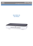
Eltek R3601-W2
SFP Gigabit Ethernet WLAN 11n Gateway
Eltek R3601-W2
User Manual
R3601-W2
User Manual
Version: R3601-W2 V.1.2
Preface
Brief Introduction
This manual provides technical information on how to configure and operate
application for your R3601-W2 unit.
Chapter 1: Provides an overview of R3601-W2
Chapter 2: Introduces the product
Chapter 3: Introduces the configuration via WEB-based Management
Intended Audience
System administrators, Network engineers and Maintenance technicians.
Style Convention
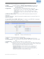
Table 1 Style convention used in this manual
Style
Meanings
Multi-level catalogs or menus are separated by ‘\’
character. For instance “file\new\directory” means the
menu item “directory” in menu “new” which in turn in the
menu “file”.
\
Used to highlight important area in diagrams.
<>
[]
{ XX | XX }
Indicates the input data from operating terminal.
Indicates one parameter configuration or a function.
Indicates a syntax of CLI command options, multiple
command options in one “{}”, separated by “|”, means
exclusive single selection.
Indicates user specified parameters.
e.g. for command:
tftp host {get | put} {sys | cfg} filename
host(italic)
The host and filename should be replaced by user
specified real parameters, such as: tftp 138.0.0.1 get
sys sysfile.bin
Table 2
Operation
Click
Double click
Drag
Convention for Mouse Operation
Meanings
Press and release a mouse button quickly
Quickly press and release a mouse button twice
Press a mouse button and move the mouse
Table 3
Style
Ctrl + C
Convention for Keyboard Operation
Meanings
“+”means an operation which presses down several keys
in the keyboard in the same time. E.g. “Ctrl + C” means
press down the key of “Ctrl” and “C” in the same time。
Table of Contents
Eltek R3601-W2 ............................................................................... 1
1 Overview .................................................................................... 1
2 Product Introduction .................................................................... 2
2.1 Appearance ............................................................................ 2
2.2 Packaging Content .................................................................. 3
2.3 Hardware Interface ................................................................. 4
2.4 Features ................................................................................ 4
2.5 Working Environment .............................................................. 5
3 Configuration Introduction ............................................................ 6
3.1 Computer Configuration ........................................................... 6
3.1.1
3.1.2
3.1.3
3.1.4
3.1.5
3.2
Device Configuration ..............................................................13
3.2.1
3.2.2
3.2.3
3.2.4
3.3
3.4
Network Status ......................................................................................................... 17
WAN Configuration .................................................................................................. 18
LAN Configuration .................................................................................................... 25
WLAN ............................................................................................................................ 28
3G Modem .................................................................................................................. 35
Port Management..................................................................................................... 37
IPv6 Configuration................................................................................................... 39
Data Service .........................................................................40
3.5.1
3.5.2
3.5.3
3.5.4
3.5.5
3.5.6
3.5.7
3.5.8
3.5.9
3.5.10
3.5.11
3.6
Connecting via Ethernet WAN............................................................................. 13
Connecting via Fiber WAN .................................................................................... 14
Web Configuration ................................................................................................... 15
Access to the Eltek R3601-W2 configuration ................................................ 16
Home ...................................................................................17
Network Configuration ............................................................17
3.4.1
3.4.2
3.4.3
3.4.4
3.4.5
3.4.6
3.4.7
3.5
Windows XP.................................................................................................................. 6
Windows Vista-32/64 ............................................................................................... 7
Windows 7-32/64 ...................................................................................................... 9
Windows 8-32/64 .................................................................................................... 10
Mac OS X 10.6 .......................................................................................................... 12
Status ........................................................................................................................... 40
DHCP Server .............................................................................................................. 42
NAT Config.................................................................................................................. 44
Firewall Config .......................................................................................................... 48
QoS................................................................................................................................ 61
DDNS ............................................................................................................................ 68
VPN ................................................................................................................................ 69
Routing ........................................................................................................................ 79
Advanced Parameters ............................................................................................ 83
Multicast .................................................................................................................. 84
USB Storage........................................................................................................... 85
System .................................................................................86
3.6.1
3.6.2
Time Management ................................................................................................... 86
Upgrade .................................................................... Fehler! Textmarke nicht definiert.
3.6.3
3.6.4
3.6.5
3.6.6
3.6.7
3.6.8
3.6.9
3.6.10
3.6.11
Reboot System ......................................................................................................... 89
Backup/Restore ........................................................................................................ 89
Diagnostic ................................................................................................................... 89
User Management.................................................................................................... 91
System Log ................................................................................................................ 92
TR069 ........................................................................................................................... 93
Choose the menu System→TR069 to load the following page. ............. 93
SNMP......................................................................................................................... 95
User Access Right ................................................................................................ 96
3.7 Apply ...................................................................................97
3.8 Print Function ........................................................................98
4 Troubleshooting ....................................................................... 102
5 Declaration of Conformity .......................................................... 108
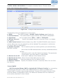
1 Overview
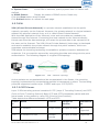
The Eltek R3601-W2 is a SFP (Fiber) Gigabit Ethernet Wireless 11n Gateway. The
Eltek R3601-W2 is perfectly fitting for SoHo, SME or extended networks.
The device provides carriers and users with accelerated access to next-generation
network services including internet and intranet access, as well as web-based
research, videoconferencing, gaming applications, e-commerce, IPTV, web hosting
and many more functions.
Eltek R3601-W2 User Manual v.1.2
1
2 Product Introduction
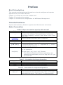
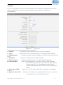
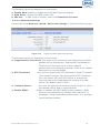
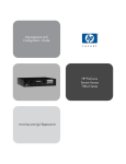
2.1 Appearance
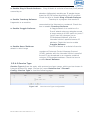
Figure 2-1
Table 2-1
LED
LED
PWR
Status
Off
Solid Green
Off
INTERNET
Slow Flash Green
SFP
Solid Green
Off
Solid Green
Off
WAN
Flash Green
Solid Green
Off
LAN1~LAN4 Flash Green
WLAN
VPN
3G
Solid Green
Off
Flash Green
Solid Green
Off
Solid Green
Off
Solid Green
Eltek R3601-W2 User Manual v.1.2
R3601-W2 Front View
Indication
Power is off
Device is running
Power is off
INTERNET type WAN PPPoE
connection authenticate failed
INTERNET type WAN connection is up
No optical signal is detected
Optical signal is detected
No Ethernet signal is detected
User data going through Ethernet
port
Ethernet interface is ready to work
No Ethernet signal is detected
User data going through Ethernet
port
Ethernet interface is ready to work
WLAN is off
User data going through WLAN
WLAN interface is ready to work
No VPN connection
VPN is established
NO Dongle connection
3G/4G connection is established
2
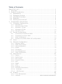
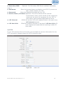
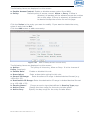
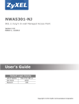
Figure 2-2
R3601-W2 Rear View
WAN: 1000/100/10Mpbs ethernet ports.
LAN: 1000/100/10Mpbs ethernet ports.
SFP: Gigabit fiber interface.
SD: Interface for SD card. (optional)
POWER: DC power input connector.
Reset button: Use the button to restore the device to the factory defaults.
WPS: WIFI WPS switch.
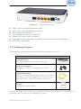
2.2 Packaging Content
Following items are included in the R3601-W2 packaging content:
Packaging Content
1x R3601-W2
SFP Gigabit Ethernet WLAN 11n Gateway
1x Power Adapter
AC Adapter, 12VDC / 1A, Model: JY-12100.
1x Ethernet cable
CAT5, UTP (unshielded twisted pair), Color yellow
(TR-068), Cord grip connectors, Connector both
side with RJ45 – 8/8 PIN, molded, length 2m
1x QsG
Printed Quick start Guide
Please note that there is no driver needed for the devices, therefore a CD-ROM is not
necessary and not part of the packaging content.
Eltek R3601-W2 User Manual v.1.2
3
2.3 Hardware Interface
Table
LAN
WAN
WIFI
SFP
USB
2-2 Hardware interface
4 100/1000BASE-T ports
1 FE ethernet port or 1 GE optical port
4 WIFI access point, support
802.11b/g/n
1 Gigabit fiber interface
1 USB 2.0 port, use for storage or 3G
modem
2.4 Features
Data Network
WAN: 1xGE,1xSFP and 1xUSB port for 2G/3G USB Modem Connectivity
LAN: 2x10/100/1000 Mbps Ethernet Port
WAN Access Mode: Static IP address, PPPoE, DHCP, PPTP and L2TP
Networking Interface: Multi WAN, Bridge Mode, 802.1Q
QOS: Destination/Source MAC/IP, Application, DSCP, Supports Bandwidth
Control
Advance Routing: Static Route, Policy Route, DNS Proxy, RIP
Internal Address Management: DHCP Server, IP and MAC Address Bind,
DHCP Relay
Networking-Protocols:
TCP/IP(IPv4/v6),UDP,RTP,SNTP,NAT,DHCP,DNS,DDNS,DLNA
VPN: IPSEC,PPTP,L2TP
IPTV: IGMP Proxy/Snooping, IPTV Bridge
Management
Management Protocol: CLI,SNMPV1/2,Tr069,Web
LED Indications: Total 12LEDS for Power, WAN/LAN, Phone
Control Button: WPS Button, WLAN Button, Power Switch, Reset Button
NAT & Firewall & Security
Supports ALG, DMZ, PAT
Firewall Protection: IDS&IPS, Block Ping/ICMP/IDENT, SPI Firewall, Portscan
restriction
Access control: Blocking by URL,IP Address, Mac Address, Protocol Type,
Port
WIFI WLAN
Standard: IEEE 802.11b/g/n(2.4GHz)
Security: WEP,WPA,WPA2,PWA-PSK,WPA2-PSK
WIFI Features: WMM,WLAN-LAN Isolation, Multi SSID(X4), AP Isolation
Eltek R3601-W2 User Manual v.1.2
4
Antenna Type: 2R2T
USB storage/Print
Support USB storage
Support print sharing
2.5 Working Environment
Environment requirement includes storage temperature, working temperature and
humidity.
Storage Temperature: -40ºC - 70ºC
Long Time Working Temperature: -10ºC - 50ºC
Short Time Working Temperature: -15ºC - 60ºC
Environment Humidity: 5% - 95% RH, no coagulation
Eltek R3601-W2 User Manual v.1.2
5
3 Configuration Introduction
3.1 Computer Configuration
Before starting the Eltek R3601-W2 configuration, please kindly configure your
computer as below, to have an automatic IP address / DNS server.
To do this, you will need to configure your PC’s network settings to obtain an IP
address automatically. Computers use IP addresses to communicate with each
other across a network or the internet.
Find out which operating system your computer is running, such as Windows XP,
Windows Vista, Windows 7, Windows 8 or Mac OS 9.x, 10.x. You can find out by
clicking on Start -> Control Panel and double-click on the System menu.
Once you know which operating system you are running, follow the directions in the
corresponding step for your computer’s operating system.
The next few pages give you step by step instruction, how to configure your TCP/IP
settings based on the type of Windows or Mac operating system you are using.
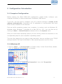
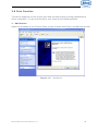
3.1.1 Windows XP
1. Click on "Start" -> "Control Panel" (in Classic View). In the Control Panel, double
click on "Network Connections" to continue.
2. Single RIGHT click on "Local Area Connection", then click "Properties".
Eltek R3601-W2 User Manual v.1.2
6
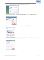
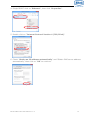
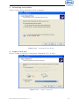
3. Double click on "Internet Protocol (TCP/IP)".
4. Check "Obtain an IP address automatically" and "Obtain DNS server address
automatically" then click on "OK" to continue.
5. Click "Show icon in notification area when connected" then Click on "OK" to
complete the setup procedures.
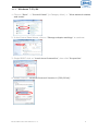
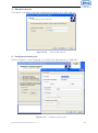
3.1.2
Windows Vista-32/64
1. Click on "Start" -> "Control Panel" -> “View network status and tasks”.
Eltek R3601-W2 User Manual v.1.2
7
2. Click on "Manage network connections" to continue.
3. Single RIGHT click on "Local Area Connection", then click "Properties".
4. Double click on "Internet Protocol Version 4 (TCP/IPv4)".
5. Check "Obtain an IP address automatically" and "Obtain DNS server address
automatically" then click on "OK" to continue.
Eltek R3601-W2 User Manual v.1.2
8
3.1.3
Windows 7-32/64
1. Click on "Start" -> "Control Panel" (in Category View) -> "View network status
and tasks".
2. In the Control Panel Home, click on "Change adapter settings" to continue.
3. Single RIGHT click on "Local Area Connection", then click "Properties".
4. Double click on "Internet Protocol Version 4 (TCP/IPv4)".
Eltek R3601-W2 User Manual v.1.2
9
5. Check "Obtain an IP address automatically" and "Obtain DNS server address
automatically" then click on "OK" to continue.
3.1.4
Windows 8-32/64
1. Move the mouse or tap to the upper right corner and click on "Settings" and go to
"Control Panel".
2. Click on "View network status and tasks".
3. In the Control Panel Home, click on "Change adapter settings" to continue.
Eltek R3601-W2 User Manual v.1.2
10
4. Single RIGHT click on "Ethernet", then click "Properties".
5. Double click on "Internet Protocol Version 4 (TCP/IPv4)".
6. Check "Obtain an IP address automatically" and "Obtain DNS server address
automatically" then click on "OK" to continue.
Eltek R3601-W2 User Manual v.1.2
11
3.1.5 Mac OS X 10.6
1. From the Apple Menu, select System Preferences.
2. Click on the Network icon in the Internet & Network area.
3. From the Show pull-down select Built-in Ethernet.
On the TCP/IP tab, select Using DHCP from the Configure pull-down menu
4. On the PPPoE tab, make sure that the Connect using PPPoE check box is NOT
activated
Click Apply Now.
5. Close the Network window.
Eltek R3601-W2 User Manual v.1.2
12
3.2 Device Configuration
3.2.1
Connecting via Ethernet WAN
The Eltek R3601-W2 is a SFP Gigabit Ethernet Gateway. It cannot be connected to the
phone network, nor can it be used as an ADSL Router.
1. Connecting Internet
With a network cable connect the uplink to the WAN port on the back of the
device.
2. Connecting PC
Use the provided Ethernet cable (yellow), connect one end of the network cable to
any interface from “LAN1” to “LAN4” and connect the other end to the PC.
3. Connecting further PC’s or a digital receiver (STB)
Use another Ethernet cable (not provided in packaging content), connect one end
of the network cable to any free interface from “LAN1” to “LAN4” and connect the
other end to your other PC, digital receiver or any other network device.
4. Connecting Power Supply
Using the supplied power adapter, connect the power cord into the round interface
on the rear panel of device
5. Power-on
Turn on the device by pressing the power switch on the side of the device. After
switching on, the front panel Power LED lights.
Eltek R3601-W2 User Manual v.1.2
13
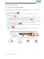
3.2.2
Connecting via Fiber WAN
The Eltek R3601-W2 is an SFP Gigabit Ethernet Gateway. It cannot be connected to
the phone network, nor can it be used as an ADSL Router.
1. SFP Slot and Fiber cable connection
1.1Put the SFP into the SFP slot on the back of the R3601-W2
1.2Connect the Fiber cable with the SFP module on the back of the device
WARNING:
- Please do not bend the fiber cable sharply. Use gradual and smooth bends to
avoid any damage on the glass fiber.
- Please do not remove the dust caps from unused fiber cables.
- To avoid signal loss, please do not touch the fiber connectors and their ends
and keep them always clean and free from dirt, debris and dust.
- Please do not look steadily at the fiber port when connecting the fiber,
because the invisible light may harm your vision.
2. Connecting PC
Use the provided Ethernet cable (yellow), connect one end of the network cable to
any interface from “LAN1” to “LAN4” and connect the other end to the PC.
3. Connecting further PC’s or a digital receiver (STB)
Use another Ethernet cable (not provided in packaging content), connect one end
of the network cable to any free interface from “LAN1” to “LAN4” and connect the
other end to your other PC, digital receiver or any other network device.
4. Connecting Power Supply
Using the supplied power adapter, connect the power cord into the round interface
on the rear panel of device
5. Power-on
Turn on the device by pressing the power switch on the side of the device. After
switching on, the front panel Power LED lights.
Eltek R3601-W2 User Manual v.1.2
14
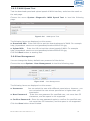
3.2.3 Web Configuration
To configure the device via web browser, please make sure that your PC obtain an IP
address automatically as described in chapter 4.1.x (Computer Configuration).
Note: At least one properly-configured PC/Notebook must be connected to the
network (either connected directly to the LAN port of the device or through Wireless
LAN).
Connecting via LAN Port
Please refer to chapter 4.2.1/4.2.2 point 2 or just connect the Ethernet cable to the
LAN port of the Eltek R3601-W2 and the other end to the LAN Port of your computer.
Connecting via Wireless LAN
To connect the device through Wireless LAN, please proceed as follows:
1. Click on the Wireless icon at the bottom right corner.
2. Choose the Eltek R3601-W2 SSID to connect through the wireless network
(SSID shown on the label on the bottom of the device )
3. Please enter your WPA Key shown on the label on the bottom of the device
4. Your computer is now connected successfully with the Eltek R3601-W2
5. To proceed with the web configuration, please refer to the next chapter.
Eltek R3601-W2 User Manual v.1.2
15
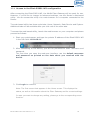
3.2.4 Access to the Eltek R3601-W2 configuration
After connecting the Eltek R3601-W2, the WLAN Fiber Gateway will be ready for use.
However, if you’d like to change its advanced settings, use the Router’s web-based
utility. You can access the utility via a web browser on a computer connected to the
Router.
The web-based utility has these main tabs: Home, Network, Data Service and System.
Additional tabs will be available after you click one of the main tabs.
To access the web-based utility, launch the web browser on your computer and please
proceed as follows:
1. Start your web browser and type the private IP address of the Eltek R3601-W2
in the URL field: 192.168.1.1
2. After connecting to the device, you will be promoted to enter username and
password.
The first time you open the web-user interface, use the default username
and password as printed on the data sheet you received with the
device.
3. Click Login to continue
Note: The first screen that appears is the Home screen. This displays the
status, as well as information about the Fiber Gateway and its current settings.
In case you want to change any setting, please go to the corresponding menu
function.
Eltek R3601-W2 User Manual v.1.2
16
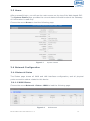
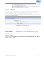
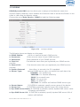
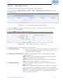
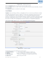
3.3 Home
After successful login, you will see the main menus on the top of the Web-based GUI.
The System Status page provides the current status information about the Gateway.
All information is read-only.
Choose the menu Home to load the following page.
Figure 3-1
System Status
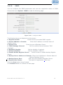
3.4 Network Configuration
3.4.1 Network Status
The Status page shows all WAN and LAN interfaces configuration, and all physical
ports connection status related to this device.
3.4.1.1 WAN Status
Choose the menu Network→Status→WAN to load the following page.
Figure 3-2
Eltek R3601-W2 User Manual v.1.2
WAN Status
17
3.4.1.2 LAN Status
Choose the menu Network→Status→LAN to load the following page.
Figure 3-3
LAN Status
3.4.1.3 Link Status
Choose the menu Network→Status→Link Status to load the following page.
Figure 3-4
Link Status
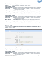
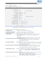
3.4.2 WAN Configuration
The device supports 4 WAN interfaces:DATA, MGMT,OTHER1,OTHER2; Every WAN
interface provides the following five Internet connection types: Static
IP,DHCP,PPPoE,PPTP,L2TP.
Choose the menu Network→WAN to load the configuration show page.
Figure 3-5
WAN page
Select an Interface Name to load the configuration page.
Eltek R3601-W2 User Manual v.1.2
18
1) Static IP
If a static IP address has been provided by your ISP, please choose the Static IP
connection type to configure the parameters for WAN port manually.
Figure 3-6
WAN-Static IP
The following items are displayed on this screen:
► Enable:
Enable this WAN interface (DATA can’t be disabled).
► Type:
Select Static IP if your ISP has assigned a static IP address for your.
► VLAN Enable: Optional. Enable VLAN to configure VLAN ID and VLAN Priority
Level.
► VLAN ID:
Optional. VLAN ID of this WAN interface.
► Priority Level: Optional. VLAN Priority Level of this WAN interface.
► Primary DNS: Enter the IP address of your ISP’s Primary DNS (Domain Name
Server). If you are not clear, please consult your ISP. It’s not
allowed to access the Internet via domain name if the Primary
DNS field is blank.
► Secondary DNS: Optional. If a Secondary DNS Server address is available, enter
it.
► IP Address:
Enter the IP address assigned by your ISP. If you are not clear,
please consult your ISP.
► Netmask:
Enter the Subnet Mask assigned by your ISP.
► Gateway:
Optional. Enter the Gateway assigned by your ISP.
Eltek R3601-W2 User Manual v.1.2
19
2) DHCP
If your ISP (Internet Service Provider) assigns the IP address automatically, please
choose the DHCP connection type to obtain the parameters for WAN port
automatically.
Figure 3-7
WAN-DHCP
The following items are displayed on this screen:
► Enable:
Enable this WAN interface (DATA can’t be disabled).
► Type:
Select DHCP if your ISP assigns the IP address automatically.
► VLAN Enable:
Optional. Enable VLAN to configure VLAN ID and VLAN Priority
Level.
► VLAN ID:
Optional. VLAN ID of this WAN interface.
► Priority Level:
Optional. VLAN Priority Level of this WAN interface.
► Primary DNS:
Enter the IP address of your ISP’s Primary DNS (Domain
Name Server) manually. If you are not clear, please
consult your ISP. It’s not allowed to access the
Internet via domain name if the Primary DNS field is
blank.
► Secondary DNS:
Optional. If a Secondary DNS Server address is available,
enter it.
► Appoint Server IP:
Optional. If network has multiple DHCP servers, enter the
IP address of your ISP’S DHCP server
Eltek R3601-W2 User Manual v.1.2
20
► Vendor Class Identifier: Optional. This option (60) is used by DHCP clients to
optionally identify the vendor type and configuration of a
DHCP client.
► Enterprise Code:
Optional.
► Manufacture Name: Optional.
► Device Class:
Optional.
► Device Type:
Optional.
► Device Version:
Optional.
3) PPPoE
If your ISP (Internet Service Provider) has provided the account information for the
PPPoE connection, please choose the PPPoE connection type (Used mainly for DSL
Internet service).
Figure 3-8
WAN-PPPoE
The following items are displayed on this screen:
► Enable:
Enable this WAN interface (DATA can’t be disabled).
► Type:
Select PPPoE if your ISP provides xDSL Virtual Dial-up connection.
► VLAN Enable:
Optional. Enable VLAN to configure VLAN ID and VLAN Priority
Level.
► VLAN ID:
Optional. VLAN ID of this WAN interface.
► Priority Level:
Optional. VLAN Priority Level of this WAN interface.
► Primary DNS:
Enter the IP address of your ISP’s Primary DNS (Domain
Name Server) manually. If you are not clear, please
consult your ISP. It’s not allowed to access the
Internet via domain name if the Primary DNS field is
blank.
Eltek R3601-W2 User Manual v.1.2
21
► Secondary DNS:
enter it.
► Username:
►
►
►
►
Optional. If a Secondary DNS Server address is available,
Enter the Account Name provided by your ISP. If you are not
clear, please consult your ISP.
Password:
Enter the Password provided by your ISP.
Service Name /AC Name: Optional. The service name and AC (Access
Concentrator) name, which should not be configured
unless you are sure it is necessary for your ISP. In
most cases, leaving these fields blank will work.
LCP Interval:
PPPoE will send an LCP echo-request frame to the peer every
LCP interval seconds.
LCP Max Fails:
PPPoE will presume the peer to be dead if LCP Max Fails LCP
echo-requests are send without receiving a valid LCP
echo-reply.
4) L2TP
If your ISP (Internet Service Provider) has provided the account information for the
L2TP connection, please choose the L2TP connection type.
Figure 3-9
Eltek R3601-W2 User Manual v.1.2
WAN-L2TP
22
The following items are displayed on this screen:
► Enable:
Enable this WAN interface (DATA can’t be disabled).
► Type:
Select L2TP if your ISP provides a L2TP connection.
► VLAN Enable:
Optional. Enable VLAN to configure VLAN ID and VLAN Priority
Level.
► VLAN ID:
Optional. VLAN ID of this WAN interface.
► Priority Level:
Optional. VLAN Priority Level of this WAN interface.
► Primary DNS:
Enter the IP address of your ISP’s Primary DNS (Domain
Name Server). If you are not clear, please consult
your ISP. It’s not allowed to access the Internet via
domain name if the Primary DNS field is blank.
► Secondary DNS:
Optional. If a Secondary DNS Server address is available,
enter it.
► Server IP:
Enter the Server IP provided by your ISP.
► Username:
Enter the Account Name provided by your ISP. If you are not
clear, please consult your ISP.
► Password:
Enter the Password provided by your ISP.
Secondary Connection: Here allow you to configure the secondary connection.
DHCP and Static IP connection types are provided.
If Static is selected:
► IP Address:
If Static IP is selected, configure the IP address of WAN port.
► Netmask:
If Static IP is selected, configure the subnet mask of WAN port.
► Gateway:
Optional. If Static IP is selected, configure the default gateway
of WAN port.
If DHCP is selected:
► Appoint Server IP:
Optional. If network has multiple DHCP servers, enter the
IP address of your ISP’s DHCP server.
►Vendor Class Identifier: Optional. This option (60) is used by DHCP clients to
optionally identify the vendor type and configuration of a
DHCP client.
► Enterprise Code:
Optional.
► Manufacture Name: Optional.
► Device Class:
Optional.
► Device Type:
Optional.
► Device Version:
Optional.
5) PPTP
If your ISP (Internet Service Provider) has provided the account information for the
PPTP connection, please choose the PPTP connection type.
Eltek R3601-W2 User Manual v.1.2
23
Figure 3-10
WAN-PPTP
The following items are displayed on this screen:
► Enable:
Enable this WAN interface (DATA can’t be disabled).
► Type:
Select PPTP if your ISP provides a PPTP connection.
► VLAN Enable:
Optional. Enable VLAN to configure VLAN ID and VLAN Priority
Level.
► VLAN ID:
Optional. VLAN ID of this WAN interface.
► Priority Level:
Optional. VLAN Priority Level of this WAN interface.
► Primary DNS:
Enter the IP address of your ISP’s Primary DNS (Domain
Name Server) manually. If you are not clear, please
consult your ISP. It’s not allowed to access the
Internet via domain name if the Primary DNS field is
blank.
► Secondary DNS:
Optional. If a Secondary DNS Server address is available,
enter it.
► Server IP:
Enter the Server IP provided by your ISP.
► Username:
Enter the Account Name provided by your ISP. If you are not
clear, please consult your ISP.
Eltek R3601-W2 User Manual v.1.2
24
► Password:
Enter the Password provided by your ISP.
► Enable Encryption: Enable PPTP link encryption.
Secondary Connection: Here allow you to configure the secondary connection.
DHCP and Static IP connection types are provided.
If Static is selected:
► IP Address:
If Static IP is selected, configure the IP address of WAN port.
► Netmask:
If Static IP is selected, configure the subnet mask of WAN port.
► Gateway:
Optional. If Static IP is selected, configure the default gateway
of WAN port.
If DHCP is selected:
► Appoint Server IP:
Optional. If network has multiple DHCP servers, enter the
IP address of your ISP’s DHCP server.
►Vendor Class Identifier: Optional. This option (60) is used by DHCP clients to
optionally identify the vendor type and configuration of a
DHCP client.
► Enterprise Code:
Optional.
► Manufacture Name: Optional.
► Device Class:
Optional.
► Device Type:
Optional.
► Device Version:
Optional.
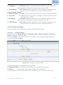
3.4.3 LAN Configuration
On this page, you can configure the parameters for LAN port.
Choose the menu Network→LAN to load the following page. There are three parts on
this page.
Figure 3-11
Eltek R3601-W2 User Manual v.1.2
LAN page
25
1) Part 1: Configure LAN interfaces
Click the Interface Name of existent LAN interface you want to modify. If you want
to delete the entry, select it and click the Del (the VLAN1 is default existed, can’t be
removed).
Click the Add button to add a new entry.
Figure 3-12
Configure LAN Interface
The following items are displayed on this part.
► Interface Name:
Name of this LAN interface.
► IP Address:
Enter the IP address for this LAN interface.
► Netmask:
Enter the subnet mask for this LAN interface.
► NAT:
Optional Enable or disable NAT for this LAN interface
► Assign NAT IP:
Optional If NAT is selected. NAT IP address can be assigned.
► Enable DHCP Server: Enable or disable DHCP server on this LAN interface.
► Start IP:
If Enable DHCP Server is selected, enter the Start IP address
to define a range for the DHCP server to assign dynamic IP
addresses. This address should be in the same IP address
subnet with the IP address of this LAN interface.
► End IP:
If Enable DHCP Server is selected, enter the End IP address to
define a range for the DHCP server to assign dynamic IP
addresses. This address should be in the same IP address
subnet with the IP address of this LAN interface.
Eltek R3601-W2 User Manual v.1.2
26
► Netmask:
►
►
►
►
If Enable DHCP Server is selected, enter the Netmask to
define a range for the DHCP server to assign dynamic IP
addresses.
Gateway:
Optional .If Enable DHCP Server is selected, enter the
Gateway address to be assigned.
Primary DNS:
Optional. If Enable DHCP Server is selected, enter the
Primary DNS server address to be assigned.
Secondary DNS:
Optional. If Enable DHCP Server is selected, enter the
Secondary DNS server address to be assigned.
Lease Time(Second): If Enable DHCP Server is selected, specify the length of
time the DHCP server will reserve the IP address for each
client. After the IP address expired, the client will be
automatically assigned a new one.
Advanced Parameter
► LAN Port:
Select the physical LAN port to bind the IP address of this LAN
interface.
► WAN Subinterface: Select the WAN subinterface which the packet from this LAN
interface can be sending to.
2) Part 2: Configure LAN Route/Bridge mode
The following items are displayed on this part.
► Port:
The physical LAN port name (LAN1~LAN4).
► Route/Bridge: Mode of this physical LAN port. The following four modes are
provided:
Route: route to WAN
Transparent bridge: not modify the packets;
Tagged bridge: LAN untagged, WAN tagged; only 1 VID
supported
Promisc Mode: Tagged packets in bridge mode, untagged
packets in route mode; most 5 VIDs supported (e.g. 8, 10, 13).
► VLAN ID List: If Tagged bridge/Promisc Mode is selected, configure the
VID/VIDs.
3) Part 3: Configure IPTV
Choose the menu Network→LAN→Advanced Parameters to load this page.
The following items are displayed on this part.
► LAN Isolate:
Check the box to prohibit the access between LAN interfaces.
► Auto Bridge:
Check the box to dynamically create IPTV bridge for STB.
► DHCP Vendor ID: Vendor class identifier List (DHCP 60 option), support at most
two vendor IDs.
► IPAddress:
IP address of interface for STB data service.
► Netmask:
Subnet mask of interface for STB data service.
► VID:
VID of IPTV VLAN.
Eltek R3601-W2 User Manual v.1.2
27
► PRI:
► Automatic:
Priority level of IPTV VLAN.
Check the box to automatically detect the VID of STB data service.
3.4.4 WLAN
Wi-Fi is a WLAN (Wireless Local Area Network) technology. It provides short-range
wireless high-speed data connections between mobile data devices (such as laptops,
PDAs or phones) and nearby Wi-Fi access points (special hardware connected to a
wired network).
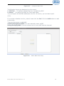
3.4.4.1 Basic Settings
Choose the menu Network→WLAN→Basic Settings to load the following page.
Figure 3-13
Configure WIFI Basic Settings
The following items are displayed on this screen:
► Enable WiFi: Enable or disable the WIFI AP function globally.
► Channel:
This field determines which operating frequency will be used. The
default channel is set to AutoSelect, so the AP will choose the best
channel automatically. It is not necessary to change the wireless
channel unless you notice interference problems with another
nearby access point.
► Wireless Mode: Select the desired mode.
11b: Select if all of your wireless clients are 802.11b.
11g: Select if all of your wireless clients are 802.11g.
11n: Select only if all of your wireless clients are 802.11n.
11b/g: Select if you are using both 802.11b and 802.11g wireless
clients.
11b/g/n: Select if you are using a mix of 802.11b, 11g and 11n
wireless clients.
► Channel Width: Select any channel width from the drop-down list. The default
setting is automatic, which can automatically adjust the channel
width for your clients. If you choose to 11n or 11b/g/n Wireless
Eltek R3601-W2 User Manual v.1.2
28
mode, this configuration is required. Two values of width are
provided: 20MHz and 20/40MHz.
The Service Set Identifier (SSID) is used to identify an 802.11 (Wi-Fi) network and
it’s discovered by network sniffing/scanning. R3601-W2 provides up to four SSID.
► Enable:
Enable or disable this entry of SSID. SSID1 can’t be disabled.
►SSID Name:
Enter the name of SSID. The name of SSID must be unique in all
wireless networks nearby.
► Bind Interface:
Select a network interface to be bridged to the SSID.
► Enable Broadcast: When wireless clients survey the local area for wireless
networks to associate with, they will detect the SSID broadcast
by the device. If you select the Enable Broadcast checkbox,
the device will broadcast its name (SSID) on the air.
► Isolated:
Enable or disable isolate different clients from the same wireless
station.
► LAN Isolated:
Enable or disable isolation between the LAN and SSID.
► Max Client:
Enter the maximum number of clients allowed to connect to the
SSID.
► SSID AP Isolated: This function can isolate wireless stations on your network
from each other. Wireless devices will be able to communicate
with the Router but not with each other. To use this function,
check this box. AP Isolation is disabled by default.
3.4.4.2 Security
Choose the menu Network→WLAN→Security to load the Security page. There are
nine wireless security modes supported by the device: Open WEP, Shared WEP, WEP
Auto, WPA-PSK, WPA2-PSK, WPAPSK/WPA2PSK, WPA, WPA2 and WPAWPA2.
If you do not want to use wireless security, select Disable, but it’s strongly
recommended to choose one of the following modes to enable security.
1) WPA-PSK, WPA2-PSK, WPAPSK/WPA2PSK: It’s the WPA/WPA2 authentication
type based on pre-shared passphrase. Choose one of these types, the following page
is loaded.
Figure 3-14
Eltek R3601-W2 User Manual v.1.2
Configure WIFI PSK Security
29
The following items are displayed on this screen:
► SSID:
The SSID enabled in WLAN→Basic Settings page.Read only
► Authentication: The authentication type selected: WPA-PSK, WPA2-PSK,
WPAPSK/WPA2PSK.
► Algorithm:
When WPA2-PSK or WPAPSK/WPA2PSK is set as the
Authentication Type, you can select either TKIP, or AES or
TKIP/AES as Encryption. When WPA-PSK is set as the
Authentication Type, you can select either TKIP or AES as
Encryption.
► WPA Pre-Shared Key: You can enter ASCII characters between 8 and 64
characters.
► Renew Interval: Specify the group key update interval in seconds. Enter 0 to
disable the update.
2) Open WEP, Shared WEP, WEP Auto: It is based on the IEEE 802.11 standard.
Choose one of these types, the following page is loaded.
Figure 3-15
Configure WIFI WEP Security
The following items are displayed on this screen:
► SSID:
The SSID enabled in WLAN→Basic Settings page.Read only
► Authentication: The authentication type selected: Open WEP, Shared WEP, WEP
Auto.
► Default Key: Select the default WEP key configure below.
► Key:
Provide up to four key. You can select the key type HEX(10/26 char) or
ASCII(5/13 char)) for encryption and then enter the key. HEX(10/26
char) and ASCII(5/13 char) formats are provided.
Hex(10/26 char): format stands for any combination of
hexadecimal digits (0-9, a-f, A-F) in the specified length.
ASCII(5/13 char): format stands for any combination of
keyboard characters in the specified length.
Eltek R3601-W2 User Manual v.1.2
30
3) WPA, WPA2, WPA/WPA2: It’s based on Radius Server. Choose one of these
types, the following page is loaded.
Figure 3-16
Configure WIFI WPA Security
The following items are displayed on this screen:
► SSID:
The SSID enabled in WLAN→Basic Settings page.Read only
► Authentication: The authentication type selected: WPA, WPA2, WPA/WPA2.
► Algorithm:
You can select either TKIP, or AES or TKIP/AES.
► Renew Interval:
Specify the update interval in seconds. Enter 0 to disable
the update.
► PMK Cache Period: Pairwise Master Key, PMK. Set WPA2 PMKID cache timeout
period, after time out, the cached key will be deleted.This parameter is valid when
you select WPA2 or WPA/WPA2.
► Enable Pre-Auth: This is used to speed up roaming before pre-authenticating
IEEE 802.1X/EAP
part of the full RSN authentication and key handshake before
actually
associating with a new AP. Default is disable. This parameter
is valid when you select WPA2 or WPA/WPA2.
► Rasius Server IP: Enter the IP address of the Radius Server.
► Rasius Server Port: Enter the port that radius service used.
► Shared Seret:
Enter the password for the Radius Server.
► Session Timeout: Specify the session timeout in seconds, Enter 0 to not limit
the timeout.
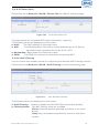
3.4.4.3 WPS
Wi-Fi Protected Setup (WPS; originally Wi-Fi Simple Config) is a computing
standard that attempts to allow easy establishment of a secure wireless home
network.WPS currently supports two methods: Personal Information Number (PIN)
and Push Button Configuration (PBC).The difference between the two methods is
much pretty described in their names.
Eltek R3601-W2 User Manual v.1.2
31
The PIN method involves entering a client device PIN, obtained either from a
client application GUI or a label on a device, into the appropriate admin screen on a
Registrar device.
The PBC method requires the user to push buttons on the Registrar and Client
devices within a two-minute period to connect them. (The two-minute period also
applies to the PIN method.) The buttons can be physical, as they typically are on AP /
router devices or virtual, as is normal on client devices.
Choose the menu Network→WLAN→WPS to load the WPS page.
1) PIN Mode
If PIN mode is selected, the following page is loaded.
Figure 3-17
Configure WIFI WPS-PIN
The following items are displayed on this screen:
► Enable WPS: Enable or disable the WIFI WPS function globally.
► WPS Mode: Choose the WPS mode: PIN.
► PIN Code: If PIN mode is chosen, enter the 8 digit PIN code, and then click
Connect.
2) PBC Mode
If PBC mode is selected, the following page is loaded.
Figure 3-18
Eltek R3601-W2 User Manual v.1.2
Configure WIFI WPS-PBC
32
The following items are displayed on this screen:
► Enable WPS: Enable or disable the WIFI WPS function globally.
► WPS Mode: Choose the WPS mode: PBC.
► PBC Set: If PBC mode is chosen, then click Simulation Connect.
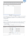
3.4.4.4 Advanced Settings
Choose the menu Network→WLAN→Advanced Settings to load the following page.
Figure 3-19
Configure WIFI Advanced Settings
The following items are displayed on this screen:
► Fragmentation Threshold: This value is the maximum size determining whether
packets will be fragmented. Setting the Fragmentation
Threshold too low may result in poor network
performance since excessive packets. 2346 is the default
setting and is recommended.
► RTS Threshold:
Here you can specify the RTS (Request to Send) Threshold.
If the packet is larger than the specified RTS Threshold
size, the device will send RTS frames to a particular
receiving station and negotiate the sending of a data
frame. The default value is 2347.
► Transmit Power:
Here you can specify the transmit power of device. 100 is
the default setting and is recommended.
► Enable WMM:
Enable or disable the WIFI WMM function globally. WMM
function can guarantee the packets with high-priority
messages, being transmitted preferentially. It is strongly
recommended enabled.
Eltek R3601-W2 User Manual v.1.2
33
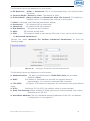
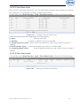
3.4.4.5 Clients Info
Choose the menu Network→WLAN→Clients Info to load the following page.
Figure 3-20
View Wifi Clients Info
This page shows all connected WIFI client information, read only.
The following items are displayed on this screen:
► MAC:
The MAC address of this client entry.
► AID:
The AID(Association ID) field is a value assigned by an AP during
association that represents the 16-bit ID of a STA.
► Bandwidth: Band width this client entry used.
► SSID:
The SSID this client entry used when connecting WIFI.
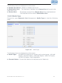
3.4.4.6 MAC Filtering
You can control the wireless access by configuring the Wireless MAC Filtering function.
Choose the menu Network→WLAN→MAC Filtering to load the following page.
Figure 3-21
View Wifi MAC Filtering
The following items are displayed on this screen:
► MAC Filtering: Enable or disable the Wifi MAC filtering function globally.
► Filtering Rules: Two MAC filtering rules are provided:
Allow: allow the stations specified by entries in the list to
access.
Deny: deny the stations specified by entries in the list to
access.
Eltek R3601-W2 User Manual v.1.2
34
To delete Wireless MAC Address filtering entries, select the entries and click the Del
button. To Add a Wireless MAC Address filtering entry, click the Add button.
Figure 3-22
Add WIFI MAC Filtering Entry
Enter the appropriate MAC Address into the MAC field. The format of the MAC Address
is XX:XX:XX:XX:XX:XX (X is any hexadecimal digit). Click Add button to add MAC
address to the Selected List, click Del button to delete the selected MAC address in
the Selected List.
3.4.5 3G Modem
Typically, 3G Modem WAN is used as uplink port as a backup. When inserting
3G Modem into USB port, the system recognized the SIM card and charges no
problem. After dialing successful, 3G Modem will serve as a backup uplink usage.
1) Basic Settings
Choose the menu Network→3G Modem to load the following page.
Figure 3-23
Eltek R3601-W2 User Manual v.1.2
Configure 3G Modem-Basic Settings
35
The following items are displayed on this screen:
► SP Network: Other or Swisscom. If it is not the target user, you need to select
the other.
► Connect Mode: Manual or Auto. The default is Auto.
► Online Mode: always online and disconnect after idle interval. The default is
“always online”. The default idle interval is 60 seconds.
If Other is selected, the following parameters appear:
► Username:
3G network dial-up username.
► Password:
3G network dial-up password.
► Dial Number: 3G network dial numbers.
► APN:
3G network access APN.
► PIN:
3G networks need to use dial-up PIN code, if not, can be set to empty.
2) Advanced Parameters
Choose the menu Network→3G Modem→Advanced Parameters to load the
following page.
Figure 3-24
Configure 3G Modem-Advanced Parameters
The following items are displayed on this screen:
► Authentication: 3G dial-up authentication, CHAP,PAP,Auto are provided.
Default is Auto.
► DNS:
The default is obtained from the dial-up network devices
automatically. You can also configure DNS manually.
► TCP MSS:
Configure TCP maximum segment, we recommend using the default
value.
► MTU:
Configure 3G link MTU, the default value is recommended
► Data Link Backup: When enabled, if WAN uplink port is disconnected, the routing
switches to the 3G link.
► Heartbeat Address: Set the heartbeat detecting address of the link, the default
configuration is not required.
Eltek R3601-W2 User Manual v.1.2
36
3) Status
Figure 3-25
Configure 3G Modem-Status
The following items are displayed on this screen:
► Device Status:
Indicates whether to insert 3G module.
► SIM Card Status: Indicates whether to insert 3G modem in the SIM card, the
ready state means the SIM card is detected.
► Product Name:
3G modem Product Type.
► Manufacturer Name: 3G modem vendor name.
► SP Name:
3G modem service provider name.
► Signal Quality:
Signal quality of 3G Modem, up to 31.
► Connection Status: Connected or disconnected.
3.4.6 Port Management
3.4.6.1 Port Mirror
Port Mirror, the packets obtaining technology, functions to forward copies of packets
from one/multiple ports (mirrored port) to a specific port (mirroring port). Usually, the
mirroring port is connected to a data diagnose device, which is used to analyze the
mirrored packets for monitoring and troubleshooting the network.
Choose the menu Network→Port Management→Port Mirror to load the following
page.
Figure 3-26
Eltek R3601-W2 User Manual v.1.2
Port Mirror
37
The following items are displayed on this screen:
► Enable Port Mirror: Enable or disable port mirror.
► Destination Port: The duplicate of packets from Source Port will send to this
destination port.
► Source Port:
All packets received from Source Port will be duplicated and
the duplicate will be send to Destination Port.
3.4.6.2 Media Type
Choose the menu Network→Port Management→Media Type to load the following
page.
Figure 3-27
Media Type
The following items are displayed on this screen:
► Media Type:
provides the following six modes to all physical ports: 10M Half
Duplex, 10M Full Duplex, 100M Half Duplex, 100M Full Duplex,
1000M Full Duplex, Auto-Negotiation.
► Current Status: Current link status of all physical ports. Read only.
Eltek R3601-W2 User Manual v.1.2
38
3.4.7 IPv6 Configuration
Choose the menu Network→IPv6 to load the following page.
Figure 3-28
Configure IPv6
The following items are displayed on this screen:
► IP Stack Version:
Choose the IP stack version to use. Provides the following
three types:
IPv4,IPv6,IPv4/v6.
WAN Configuration
► Enable WAN:
If IPv6 or IPv4/v6 is chosen, select this to enable IPv6 stack
on WAN.
► Access Mode:
Select access mode of WAN: IP or PPP.
► Link-Local Address:
Select type of Link-Local address: Auto or Manual. If
Manual is selected, you should specify address manually.
► Global Unicast Address: Stateless,Manual,DHCPv6. If Manual is selected, you
should specify address manually.
► Default Gateway Address: Stateless,Manual. If Manual is selected, you should
specify address manually.
► DNS:
Stateless,Manual,DHCPv6. If Manual is selected, you should
specify DNS manually.
► Enable DHCP-PD:
Whether to enable DHCP-PD(prefix delegation) on WAN.
Eltek R3601-W2 User Manual v.1.2
39
LAN Configuration
► Enable LAN:
If IPv6 or IPv4/v6 is choseN, select this to enable IPv6 stack
on LAN.
► Link-Local Address: Select type of Link-Local address: Auto or Manual. If
Manual is selected, you should specify address manually.
► Global Unicast Address: Manual,Auto. If Manual is selected, you should specify
address manually.
► Address Auto Allocate Mode: SLAAC+RDNSS(Recursive DNS Server)
SLAAC(Stateless address autoconfiguration)+DHCPv6
DHCPv6
► Manual Allocate Address Prefix: Configure the manual allocate address prefix.
► Prefix Life Time:
Enter the life time of prefix.
► Default Gateway Life Time: Enter the life time of default gateway.
► Primary DNS:
Enter the primary DNS address.
► Secondary DNS:
Enter the secondary DNS address.
3.5 Data Service
3.5.1 Status
The Status page shows the data services information, all information is read only.
3.5.1.1 Service State
The Service State page show all switch status of data services.
Choose the menu Data Service→Status→Service State to load the following page.
Figure 3-29
Eltek R3601-W2 User Manual v.1.2
Service State
40
3.5.1.2 ARP Table
This page displays the ARP List;
Choose the menu Data Service→Status→ARP Table to load the following page.
Figure 3-30
ARP Table
3.5.1.3 Route Table
Choose the menu Data Service→Status→Route Table to load the following page.
Figure 3-31
Eltek R3601-W2 User Manual v.1.2
Route Table
41
3.5.1.4 Net State
Choose the menu Data Service→Status→Net State to load the following page.
Figure 3-32
Net State
3.5.2 DHCP Server
3.5.2.1 Static Address Assign
Choose the menu Data Service→DHCP Server→Static Address Assign, and then
you can view and add address which is assigned for clients. When you specify a static
IP address for a client on the LAN, that client will always receive the same IP address
each time when it accesses the DHCP server. The Reserved IP addresses should be
assigned to the devices that require permanent IP settings.
Figure 3-33
Eltek R3601-W2 User Manual v.1.2
View Static Address Assign Configuration
42
Click the Index in the entry you want to modify. If you want to delete the entry,
select it and click the Del.
Click the Add button to add a new entry.
Add or Modify An Static Address Assign Entry
Figure 3-34
The following items are displayed on this screen:
► Client IP Addres: The IP address reserved.
► Client Mask:
The subnet mask of IP address reserved.
► Client MAC:
The MAC address you want to reserve IP address.
► Description:
The description of the entry to add or modify.
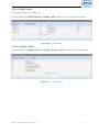
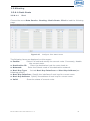
3.5.2.2 Status
Choose the menu Data Service→DHCP Server→Status, and then you can view the
information about the clients attached to the DHCP server.
Figure 3-35
DHCP Client Status
3.5.2.3 DHCP Relay
A DHCP relay agent is any host that forwards DHCP packets between clients and
servers. Relay agents are used to forward requests and replies between clients and
servers when they are not on the same physical subnet. Relay agent forwarding is
distinct from the normal forwarding of an IP router, where IP datagrams are switched
between networks somewhat transparently. By contrast, relay agents receive DHCP
messages and then generate a new DHCP message to send on another interface. It
listens for client requests and adds vital configuration data, such as the client's link
information, which is needed by the server to allocate the address for the client. When
the DHCP server responds, the DHCP relay agent forwards the reply back to the DHCP
client.
Eltek R3601-W2 User Manual v.1.2
43
Figure 3-36
DHCP Relay Overview
Choose the menu Data Service→DHCP Server→DHCP Relay to load the following
page.
Figure 3-37
Configure DHCP Relay
The following items are displayed on this screen:
► Enable DHCP Relay: Enable or disable DHCP Relay.
► Client Interface: The interface to listen for DHCP client requests. Up to four
interfaces can be selected.
► Server Interface: Choose the interface which connects DHCP server.
► Server IP:
Configure the DHCP server IP address.
3.5.3 NAT Config
Network Address Translation (NAT) is a network protocol used in IPv4 networks
that allows multiple devices to connect a network protocol using the same public IPv4
address. NAT was originally designed in an attempt to help conserve IPv4 addresses.
NAT modifies the IP address information in IPv4 headers while in transit across a
traffic routing device.
Eltek R3601-W2 User Manual v.1.2
44
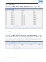
3.5.3.1 Basic Settings
Choose the menu Data Service→NAT Config→Basic Settings to load the following
page.
Figure 3-38
Basic Settings
The following items are displayed on this screen:
► Max Nat Connections:
Specify the maximum number of NAT connections.
► Enable MSS Auto Adaptive: Enable or disable auto adaptive the value of
MSS(Maximum Segment Size).
► TCP MSS:
If Enable MSS Auto Adaptive is not selected, configure this
to specify the maximum segment size of the TCP
protocol.
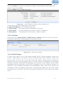
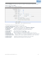
3.5.3.2 PAT Settings
Several internal addresses can be NATed to only one or a few external addresses by
using a feature called overload, which is also referred to as PAT. PAT is a subset of
NAT functionality, where it maps several internal addresses to a single external
address. PAT statically uses unique port numbers on a single outside IP address to
distinguish between the various translations.
Choose the menu Data Service→NAT Config→PAT Settings to load the following
page.
Figure 3-39
Eltek R3601-W2 User Manual v.1.2
View PAT Settings
45
The following items are displayed on this screen:
► Enable PAT: Enable or disable PAT globally.
Click the Index in the entry you want to modify. If you want to delete the entry,
select it and click the Del.
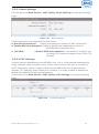
Click the Add button to add a new entry.
Figure 3-40
Add or Modify PAT Entry
The following items are displayed on this screen:
► Enable:
Enable or disable this PAT entry.
► Internet Port:
Enter the service port provided for accessing external network.
All the requests from internet to this service port will be
redirected to the specified server in local network.
► Intranet Port:
Specify the service port of the LAN host as virtual server.
► Intranet IP:
Enter the IP address of the specified internal server for the
entry. All the requests from the internet to the specified
LAN port will be redirected to this host.
► Protocol:
Specify the protocol used for the entry.
► Internet Interface: Specify the interface to receive requests from the internet for
the entry.
► Description:
Enter a name for Virtual Server entry.
Eltek R3601-W2 User Manual v.1.2
46
3.5.3.3 DMZ Settings
In computer security, a DMZ or Demilitarized Zone (sometimes referred to as a
perimeter network) is a physical or logical network that contains and exposes an
organization's external-facing services to a larger and insecure network, usually the
Internet. The purpose of a DMZ is to add an additional layer of security to an
organization's local area network (LAN); an external attacker only has direct access to
equipment in the DMZ, rather than any other part of the network.
Choose the menu Data Service→NAT Config→DMZ Settings to load the following
page.
Figure 3-41
View DMZ Settings
The following items are displayed on this screen:
► Enable DMZ: Enable or disable DMZ globally.
Click the Index in the entry you want to modify. If you want to delete the entry,
select it and click the Del.
Click the Add button to add a new entry.
Figure 3-42
Add or Modify DMZ Entry
The following items are displayed on this screen:
► DMZ Public IP: The public IP address for this DMZ entry.
► DMZ Private IP: The private IP address for this DMZ entry.
► Description:
Enter a description string for this DMZ entry
Eltek R3601-W2 User Manual v.1.2
47
3.5.3.4 ALG Settings
Application Layer Gateway (ALG) allows customized Network Address Translation
(NAT) traversal filters to be plugged into the gateway to support address and port
translation for certain application layer "control/data" protocols such as FTP, H.323,
PPTP, etc.
Choose the menu Data Service→NAT Config→ALG Settings to load the following
page.
Figure 3-43
ALG Settings
The following items are displayed on this screen:
► Enable SIP: Enable or disable SIP ALG.
► Enable H323: Allow Microsoft NetMeeting clients to communicate across NAT if
selected.
► Enable FTP: Allow FTP clients and servers to transfer data across NAT if selected.
► Enable PPTP: Enable or disable PPTP ALG.
► Enable RTSP: Enable or disable RTSP ALG.
3.5.4 Firewall Config
3.5.4.1 Attack Defense
With Attack Defense function enabled, the device can distinguish the malicious
packets and prevent the port scanning from external network, so as to guarantee the
network security. Configure this for abnormal packets defense and flood attack
defense. Flood attack is a commonly used DoS (Denial of Service) attack, including
TCP SYN, UDP, ICMP, and so on.
Choose the menu Data Service→Firewall Config→Attack Defense to load the
following page.
Eltek R3601-W2 User Manual v.1.2
48
Figure 3-44
Attack Defense
The following items are displayed on this screen:
► Enable Broadcast Storm Defense:
Enable or disable Broadcast Storm
Defense.
► Enable Block Ping:
Enable or disable Block Ping function.
► Enable TCP SYN Flood Defense: Enable or disable TCP SYN Flood Defense.
► Enable UDP Flood Defense:
Enable or disable UDP Flood Defense.
► Enable ICMP Defense:
Enable or disable ICMP Defense.
► Enable ARP Attack Defense:
Enable or disable ARP Attack Defense.
► Enable Port Scan Defense:
A port scanner is a software application
designed to probe a server or host for
open ports. Check the box to prevent
port scanning.
► Enable Land Based Defense:
The Land Denial of Service attack
works by sending a spoofed packet
with the SYN flag - used in a
"handshake" between a client and a
host - set from a host to any port that
is open and listening. If the packet is
programmed to have the same
destination and source IP address,
when it is sent to a machine, via IP
spoofing, the transmission can fool the
machine into thinking it is sending
itself a message, which, depending on
the operating system, will crash the
machine. Check the box to enable
Land Based Defense.
Eltek R3601-W2 User Manual v.1.2
49
► Enable Ping Of Death Defense: Ping of death is a denial of service (DoS) attack
caused by an
attacker deliberately sending an IP packet larger
than the 65,536 bytes allowed by the IP protocol.
Check the box to enable Ping of Death Defense.
► Enable Teardrop Defense:
Teardrop is a program that sends IP
fragments to a machine
connected to the Internet or a network. Check the
box to enable Teardrop Defense.
► Enable Fraggle Defense:
A fraggle attack is a variation of a
Smurf attack where an attacker sends
a large amount of UDP traffic to ports 7
(echo) and 19 (chargen) to an
IP Broadcast Address, with the
intended victim's spoofed source IP
address. Check the box to enable
Fraggle Defense.
► Enable Smurf Defense:
The Smurf Attack is a denial-of-service
attack in which large
numbers of Internet Control Message Protocol
(ICMP) packets with the intended victim's spoofed
source IP are broadcast to a computer network
using an IP Broadcast address. Check the box to
enable Smurf Defense.
3.5.4.2 Service Type
Service Type defines the entry with protocol and port range, which can be chosen in
Internet Access-Ctrl page. Choose the menu Data Service→Firewall
Config→Service Type to load the following page.
Figure 3-45
Eltek R3601-W2 User Manual v.1.2
View Service Type Configuration
50
Click the Index in the entry you want to modify. If you want to delete the entry,
select it and click the Del.
Click the Add button to add a new entry.
Figure 3-46
Add or Modify Service Type Entry
The following items are displayed on this screen:
► Name:
Name of this entry, it will be list in Internet Access-Ctrl page.
► Protocol: Select the protocol for this entry. Four types are provided: TCP, UDP,
ICMP and ALL.
► Port Range: Configure the port range for this entry.
► Description: Enter a description string for this entry
3.5.4.3 Internet Access-Ctrl
Each sub-page under this page is used to control Internet access.
3.5.4.3.1
Access Control
This sub-page is used to control Internet access through IP, port, and time.
Choose the menu Data Service→Firewall Config→Internet Access-Ctrl→Access
Control to load the following page.
Figure 3-47
Eltek R3601-W2 User Manual v.1.2
View Access Control Entry
51
The following items are displayed on this screen:
► Enable Access Control: Enable or disable access control from WAN.
► Policy:
Default policy of access control: Allow or Deny. If Allow is
selected, all packets will be allowed except the entries
list on this page. If Deny is selected, all packets will
be denied except the entries list on this page.
Click the Index in the entry you want to modify. If you want to delete the entry,
select it and click the Del.
Click the Add button to add a new entry.
Figure 3-48
Add or Modify Access Control Entry
The following items are displayed on this screen:
► Action:
The policy of this entry, Allow or Deny. It is the inverse of
Policy. Read only.
► Enable Rule:
Enable or disable this rule.
► Description:
Enter a description string for this rule
► Source IP Range:
Enter the source IP range in dotted-decimal format (e.g.
192.168.1.23).
► Destination IP Range: Enter the destination IP range in dotted-decimal format
(e.g. 192.168.1.23).
► Service Name:
Choose a service type that defined in Service Type page.
► Active Time:
Specify the time range for the entry to take effect.
► Active Day:
Specify the day range for the entry to take effect.
Eltek R3601-W2 User Manual v.1.2
52
3.5.4.3.2
User Authentication
This sub-page is used to control Internet access through username and password.
Choose the menu Data Service→Firewall Config→Internet Access-Ctrl→User
Authentication to load the following page.
Figure 3-49
View User Authentication Entry
The following items are displayed on this screen:
► Enable User Authentication: Enable or disable user authentication globally. If
enabled, only the following list of users and passwords can access the Internet. Press
Save button if you have modified this parameter.
Click the Index in the entry you want to modify. If you want to delete the entry,
select it and click the Del.
Click the Add button to add a new entry.
Figure 3-50
Add or Modify User Authentication Entry
The following items are displayed on this screen:
► Username: Enter the username of this entry.
► Password: Enter the password of this entry.
► Auth Mode: Choose the authentication mode of this entry. Provides four modes:
Allow Multi-PC Access: Allows multiple computers to access the
Internet using this account.
Allow One PC Access: Only allows one computer to access the
Internet using this account.
Eltek R3601-W2 User Manual v.1.2
53
Allow Special IP Access: Allowing only specified IP computer uses
this account to access the Internet.
Allow Special MAC Access: Allowing only specified MAC computer
uses this account to access the Internet
3.5.4.3.3
Page Push
HTTP Page push is a mechanism for sending unsolicited (asynchronous) data from
web server to a web browser. When accessing the Internet for the first time, the
specified HTTP page will be pushed to the browser when enabled.
Choose the menu Data Service→Firewall Config→Internet Access-Ctrl→Page
Push to load the following page.
Figure 3-51
Configure Page Push
The following items are displayed on this screen:
► Enable Page Push: If enabled, push specified HTTP page to the browser when
accessing the Internet for the first time.
► Push Http Url:
Specifies the HTTP URL of the page you want to push.
3.5.4.4 Network Access-Ctrl
3.5.4.4.1
WEB
Choose the menu Data Service→Firewall Config→Netword Access-Ctrl→WEB to
load the following page.
Eltek R3601-W2 User Manual v.1.2
54
Figure 3-52
Configure WEB Access-Ctrl
The following items are displayed on this screen:
► HTTP Port:
Port used with HTTP access device.
HTTP: Hypertext Transfer Protocol.
► HTTPS Port: Port used with HTTPS access device.
HTTPS: it is the result of simply layering the Hypertext Transfer
Protocol (HTTP) on top of the SSL/TLS protocol.
Internet Web Access:
► Allow Access: If enabled, allow user to access the device from the Internet via
WEB.
► IP Limit:
If enabled, allow only specific IP range to access the device from
the Internet via WEB.
► IP Range:
If IP Limit enabled, specifies the IPv4 address range that is only
allowed to access to the device from the Internet via WEB.
► IPv6 Range:
If IP Limit enabled, specifies the IPv6 address range that is only
allowed to access to the device from the Internet via WEB.
Intranet Web Access:
► Allow Access: If enabled, allow user to access the device from the Intranet via
WEB.
► IP Limit:
If enabled, allow only specific IP range to access the device from
the Intranet via WEB.
► IP Range:
If IP Limit enabled, specifies the IPv4 address range that is only
allowed to access the device from the Intranet via WEB.
► IPv6 Range:
If IP Limit enabled, specifies the IPv6 address range that is only
allowed to access the device from the Intranet via WEB.
3.5.4.4.2
TELNET
Choose the menu Data Service→Firewall Config→Netword Access-Ctrl→TELNET
to load the following page.
Eltek R3601-W2 User Manual v.1.2
55
Figure 3-53
Eltek R3601-W2 User Manual v.1.2
Configure Telnet Access-Ctrl
56
The following items are displayed on this screen:
► Port:
Port when using telnet tools access device.
Internet Web Access:
► Allow Access: If enabled, allow access to the device from the Internet via telnet.
► IP Limit:
If enabled, allow only specific IP range to access the device from
the Internet via telnet
► IP Range:
If IP Limit enabled, specifies the IPv4 address range that only
allow access to the device from the Internet via telnet.
► IPv6 Range:
If IP Limit enabled, specifies the IPv6 address range that only
allow access to the device from the Internet via telnet.
Intranet Web Access:
► Allow Access: If enabled, allow access to the device from the Intranet via telnet.
► IP Limit:
If enabled, allow only specific IP range to access the device from
the Intranet via telnet
► IP Range:
If IP Limit enabled, specifies the IPv4 address range that only
allow access to the device from the Intranet via telnet.
► IPv6 Range:
If IP Limit enabled, specifies the IPv6 address range that only
allow access to the device from the Intranet via telnet.
3.5.4.4.3
SSH
Choose the menu Data Service→Firewall Config→Netword Access-Ctrl→SSH to
load the following page.
Figure 3-54
Configure SSH Access-Ctrl
The following items are displayed on this screen:
► Port:
Port when using SSH tools access device.
Internet Web Access:
► Allow Access: If enabled, allow access to the device from the Internet via SSH.
► IP Limit:
If enabled, allow only specific IP range to access the device from
the Internet via SSH
Eltek R3601-W2 User Manual v.1.2
57
► IP Range:
If IP Limit enabled, specifies the IPv4 address range that only
allow access to the device from the Internet via SSH.
► IPv6 Range:
If IP Limit enabled, specifies the IPv6 address range that only
allow access to the device from the Internet via SSH.
Intranet Web Access:
► Allow Access: If enabled, allow access to the device from the Intranet via SSH.
► IP Limit:
If enabled, allow only specific IP range to access the device from
the Intranet via SSH
► IP Range:
If IP Limit enabled, specifies the IPv4 address range that only
allow access to the device from the Intranet via SSH.
► IPv6 Range:
If IP Limit enabled, specifies the IPv6 address range that only
allow access to the device from the Intranet via SSH.
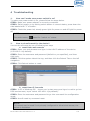
3.5.4.5 Filter Strategy
Each sub-page under this page is used to filter Internet access.
3.5.4.5.1
Keyword Filter
Choose the menu Data Service→Firewall Config→Filter Strategy→Keyword
Filter to load the following page.
Click the Index in the entry you want to modify. If you want to delete the entry,
select it and click the Del.
Click the Add button to add a new entry.
Figure 3-55
Configure Keyword Filter
The following items are displayed on this screen:
► Keyword Filter: If enabled, packet filtering is enabled by keyword.
► Policy:
The policy for filtering web page, Deny and Allow.
You can export all the keywords as a file. Of course, you can also import a file.
Eltek R3601-W2 User Manual v.1.2
58
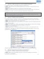
3.5.4.5.2
IP Filter
On this page, you can control the Internet access of local hosts by specifying their IP
addresses.
Choose the menu Data Service→Firewall Config→Filter Strategy→IP Filter to
load the following page.
Click the Index in the entry you want to modify. If you want to delete the entry,
select it and click the Del.
Click the Add button to add a new entry.
Figure 3-56
Configure IP Filter
The following items are displayed on this screen:
► IP Filter: If enabled, packet filtering is enabled by IP address.
► Policy: The policy for IP address list. Deny and Allow.
You can export all the IP addresses as a file. Of course, you can also import a file.
3.5.4.5.3
MAC Filter
On this page, you can control the Internet access of local hosts by specifying their
MAC addresses.
Choose the menu Data Service→Firewall Config→Filter Strategy→MAC Filter to
load the following page.
Eltek R3601-W2 User Manual v.1.2
59
Figure 3-57
Configure MAC Filter
The following items are displayed on this screen:
► IP Filter: If enabled, packet filtering is enabled by MAC.
► Policy: The policy for MAC list. Deny and Allow.
You can export all the MAC addresses as a file. Of course, you can also import
a file.
If you want to delete an entry, select it and click the Del. Click the Add button to add
a new entry.
There are two ways to add MAC:
Artificial designated MAC: You can manually enter a MAC.
Using Studying MAC: You can choose one or more MAC devices learned.
Figure 3-58
Eltek R3601-W2 User Manual v.1.2
Add a MAC Filter Entry
60
3.5.4.6 IP&MAC Binding
Choose the menu Data Service→Firewall Config→IP&MAC Binding to load the
following page.
There are two ways to add a binding entry: You can manually enter a pair of IP and
MAC, and then press Add Item. Alternatively you can select a pair of IP and MAC in
Scan List that device learned.
Figure 3-59
Configure IP&MAC Binding
3.5.5 QoS
3.5.5.1 Basic Settings
QOS feature is enabled by default, based on 802.1P, strict priority scheduling mode.
The device supports four priority queues, when QOS feature enabled.
Choose the menu Data Service→QoS→Basic Settings to load the following page.
Figure 3-60
Eltek R3601-W2 User Manual v.1.2
Configure QoS Basic Settings
61
The following items are displayed on this screen:
Global Parameters
► Qos Enable:
Enable or disable QoS functionality.
► Scheduling Mode:
PQ: PQ means strict priority, that is, when congestion
occurs, first sending packets of high priority queue.
WRR: All queues use weighted fair queuing scheme which
is defined in Weight Ratio
PQ+WRR: Only highest queue use strict priority; others
use weighted fair queuing scheme.
► Qos Priority:
DSCP: When you select DSCP value, corresponding to the
following relationship.
DSCP priority value
Priority queue (queue 3 highest
priority)
0-15
Queue 0
16 ~ 31
Queue 1
32 to 47
Queue 2
48 ~ 63
Queue 3
802.1P: Select the queue classification mode, when
selecting 802.1P mode, depending on the value of 802.1p
priority classification into different queues, corresponding
to the following relationship.
801.1p priority value Priority queue (queue 3 highest
priority)
0 to 1
Queue 0
2.3
Queue 1
4.5
Queue 2
6-7
Queue 3
Bandwidth Setting
► Upstream Bandwidth:
Configure the bandwidth of upstream.
► Downstream Bandwidth: Configure the bandwidth of downstream.
Advanced Parameters
► Enable Video Reservation:
reserved for video
Enable video reservation and give the value to
► Remap Tos/DSCP to CoS:
Check the box that the system will remark 802.1P
value with TOS/DSCP of upstream packets, the
mapping relationship is as follows:
DSCP priority value
802.1p priority
0-7
0
8-15
1
16 ~ 23
2
24 ~ 31
3
32 to 39
4
40 ~ 47
5
48 ~ 55
6
56 to 63
7
Eltek R3601-W2 User Manual v.1.2
62
3.5.5.2 Port Rate Limit
Rate limit for physical LAN ports, you can select the package type restrictions limiting
the entrance. All multiples of 32kbps speed requirements
Choose the menu Data Service→QoS→Port Rate Limit to load the following page.
Figure 3-61
Configure Qos Port Rate Limit
The following items are displayed on this screen:
► Port:
Physical LAN port
► Enable:
Enable or disable rate limit function.
► Incoming Rate Limit: Enter incoming maximum rate, which must is times of
32Kbsp.
►Limit Packet Type:
Select the packet type which is limited rate.
► Outgoing Rate Limit:
Enter Outgoing maximum rate, which must is times of
32Kbsp.
3.5.5.3 Flow Rate Limit
Choose the menu Data Service→QoS→Flow Rate Limit to load the following page.
Figure 3-62
Eltek R3601-W2 User Manual v.1.2
View QoS Flow Rate Limit Entry
63
Click the Index in the entry you want to modify. If you want to delete the entry,
select it and click the Del.
Click the Add button to add a new entry.
Figure 3-63
Configure Qos Flow Rate Limit
The following items are displayed on this screen:
► IP Range:
The IP range of LAN’s PC.
► Active Time:
If not configured, which means that all time are in active
► Active Day:
If not configured, which means that all time in active
► Direction:
Up: Check the frame from the direction of the LAN port
to the WAN port, and match the source IP and
destination port;
Down: Check the frame from the direction of the WAN
port to the LAN port, and match the destination IP and
source port;
Bidirectional: Limit both upstream and downstream
speed.
► Limited Bandwidth(CIR): The limited bandwidth.
► Maximal Bandwidth(PIR): The maximum bandwidth.
If Application is selected:
► Application Protocol:
etc.
Such as HTTP, HTTPS, FTP, TFTP, SMTP, POP3, TELNET,
If Custom is selected, the following page will be loaded:
Figure 3-64
Eltek R3601-W2 User Manual v.1.2
Configure Custom of Qos Flow Rate Limit
64
The following items are displayed on this screen:
► Protocol Type: Custom protocol type, UDP or TCP.
► Port Range: Set port range.
3.5.5.4 Service
The device supports to remap scheduling priority and remark the value of DSCP or
802.1P according to the service type.
Choose the menu Data Service→QoS→Service to load the following page.
Figure 3-65
View Qos Service
The following items are displayed on this screen:
► Name:
Service name. Read only.
► Remap Queue Priority: Check the box to remap scheduling queue.
► Priority:
There are four levels of priority. Priority 3 is highest, and priority
0 is the lowest
► Remark 802.1p:
Check the box to enable 802.1p priority remarking.
► 802.1p Value:
The value of remarking 802.1P.
► Remark DSCP:
Check the box to enable DSCP remarking.
► DSCP Value:
The value of remarking DSCP.
3.5.5.5 ACL
Choose the menu Data Service→QoS→ACL to load the following page.
Eltek R3601-W2 User Manual v.1.2
65
Figure 3-66
View Qos ACL
Click the Del in the entry you want to delete.
Click the Index or Detail in the entry you want to modify, and then the following
page will be loaded:
Figure 3-67
Modify Qos ACL
The following items are display on this page:
Condition:
► Rule Name:
The custom name.
► Physical Port: Rule’s source port
► Rule Type:
Type of rule: L2 data or L3 data.
If L3 Data is selected:
Figure 3-68
L3 Data Rule Type
The following items are display on this page:
► Src IP/Netmask: The source IP address and netmask of packets, such is
192.168.100.1/255.255.255.0.
► Dest IP/Netmask: The destination IP address and netmask of packets.
Eltek R3601-W2 User Manual v.1.2
66
► Protocol:
E.g. ICMP, UDP, TCP, or custom IP protocol types.
► L4 Src Port:
Source port range.
► L4 Dest Port:
Destination port range.
If L2 Data is selected:
Figure 3-69
L2 Data Rule Type
The following items are display on this page:
► SRC MAC:
Source MAC address of packets.
► DEST MAC:
Destination MAC address of packets.
► Ether Type:
The ether type of packets.
► VLAN ID:
The VLAN id of packets.
► 802.1p:
The VLAN priority of packets.
Action
► Drop:
Drop the packets matched with the rule.
► Remark VID:
Change the VID of packets matched with the rule.
► Remark 802.1p:
Change the 802.1P priority of packets matched with the rule.
► Remark DSCP:
Change the DSCP of packets matched with the rule.
► Priority:
Change the scheduling queue of packets matched with the rule.
► Maximal Bandwidth: Limit the bandwidth of packet matched with the rule.
Eltek R3601-W2 User Manual v.1.2
67
3.5.6 DDNS
DDNS(Dynamic DNS) service allows you to assign a fixed domain name to a
dynamic WAN ip address, which enables the Internet hosts to access the Router or the
hosts in LAN using the domain names.
Choose the menu Data Service→DDNS to load the following page.
Figure 3-70
Configure DDNS
The following items are display on this page:
► DDNS Enable:
Active or inactive dynamic DNS service.
► Username:
Enter account name of your DDNS account.
► Password:
Enter password of your DDNS account.
► First Url:
First domain name that you registered your DDNS service
provider.
► Second Url:
First domain name that you registered your DDNS service
provider.
► Update Interval:
How often, in seconds, the IP is updated.
► Server Type:
optional DDNS server type, can select from pull-dwon list:
DYNDNS: For dyndns.org
FREEDNS: For freedns.afraid.org
ZONE: For zoneedit.com
NOIP: For no-ip.com
3322: For 3322.org
CUSTOM: For custom self-defined DDNS server type.
► Server Name:
If CUSTOM is selected, specify server name of the device.
► Server Url:
If CUSTOM is selected, specify server URL of the device.
► Dyn DNS Server Name: If CUSTOM is selected, specify dyndns DNS server name
of custom self-defined.
► Dyn DNS Server Url: If CUSTOM is selected, specify dyndns DNS server URL of
custom self-defined.
Eltek R3601-W2 User Manual v.1.2
68
► System Item:
If CUSTOM is selected, specify system item of custom selfdefined.
► DDNS Status:
Display the status of DDNS service. Read only.
Click the Save button when finished.
Click Refresh button to refresh the web page.
3.5.7 VPN
VPN (Virtual Private Network) is a private network established via the public
network, generally via the Internet. However, the private network is a logical network
without any physical network lines, so it is called Virtual Private Network.
With the wide application of the Internet, more and more data are needed to be
shared through the Internet. Connecting the local network to the Internet directly,
though can allow the data exchange, will cause the private data to be exposed to all
the users on the Internet. The VPN (Virtual Private Network) technology is developed
and used to establish the private network through the public network, which can
guarantee a secured data exchange.
VPN adopts the tunneling technology to establish a private connection between two
endpoints. It is a connection secured by encrypting the data and using point-to-point
authentication. The following diagram is a typical VPN topology.
Figure 3-71
VPN – Network Topology
As the packets are encapsulated and de-encapsulated in the Router, the tunneling
topology implemented by encapsulating packets is transparent to users. The tunneling
protocols supported contain Layer 3 IPSEC and Layer 2 L2TP/PPTP.
3.5.7.2 PPTP Server
Layer 2 VPN tunneling protocol consists of L2TP (Layer 2 Tunneling Protocol) and PPTP
(Point to Point Tunneling Protocol).Both L2TP and PPTP encapsulate packet and add
extra header to the packet by using PPP (Point to Point Protocol).
Table depicts the difference between L2TP and PPTP.
Protoc
ol
Media
Tunnel
Length of
Header
Authenticat
ion
PPTP
IP network
Single tunnel
6 bytes at least
Not
supported
L2TP
IP network of UDP
Multiple
tunnels
4 bytes at least
Supported
Eltek R3601-W2 User Manual v.1.2
69
Figure 3-72
Difference between L2TP and PPTP
Choose the menu Data Service→VPN→PPTP Server to load the following page.
Figure 3-73
Configure PPTP Server
The following items are displayed on this screen:
► Enable PPTP Server:
Enable or disable the PPTP server function globally.
► IP Address Pool Range: Specify the start and the end IP address for IP Pool. The
start IP address should not exceed the end address
and the IP ranges must not overlap.
► Enable Authentication: Specify whether to enable authentication for the tunnel.
► Enable Encryption:
Specify whether to enable the encryption for the tunnel. If
enabled, the PPTP tunnel will be encrypted by MPPE.
Click the Index in the entry you want to modify. If you want to delete the entry,
select it and click the Del.
Click the Add button to add a new entry.
Figure 3-74
Add or Modify PPTP Client Entry
The following items are displayed on this screen:
► Username: Enter the account name of PPTP tunnel. It should be configured
identically on server and client.
► Password: Enter the password of PPTP tunnel. It should be configured identically
on server and client.
► Binding IP: Enter the IP address of the client which is allowed to connect to this
PPTP server.
► Description: Enter the humane readable description for this account.
Eltek R3601-W2 User Manual v.1.2
70
3.5.7.3 L2TP Server
Choose the menu Data Service→VPN→L2TP Server to load the following page.
Figure 3-75
Configure L2TP Server
The following items are displayed on this screen:
► Enable L2TP Server:
Enable or disable the L2TP server function globally.
► Local IP:
Enter the local IP address of L2TP server.
► IP Address Pool Range: Specify the start and the end IP address for IP Pool. The
start IP address should not exceed the end address
and the IP ranges must not overlap.
► Enable Authentication: Specify whether to enable authentication for the tunnel.
If enabled, enter the authentication secret.
► Enable Debug:
Specify whether to enable the debug for L2TP.
Click the Index in the entry you want to modify. If you want to delete the entry,
select it and click the Del.
Click the Add button to add a new entry.
Figure 3-76
Eltek R3601-W2 User Manual v.1.2
Add or Modify L2TP Client Entry
71
The following items are displayed on this screen:
► Username: Enter the account name of L2TP tunnel. It should be configured
identically on server and client.
► Password: Enter the password of L2TP tunnel. It should be configured identically
on server and client.
► Binding IP: Enter the IP address of the client which is allowed to connect to this
L2TP server.
► Description: Enter the humane readable description for this account.
3.5.7.4 IPSEC
IPSEC (IP Security) is a set of services and protocols defined by IETF (Internet
Engineering Task Force) to provide high security for IP packets and prevent attacks.
To ensure a secured communication, the two IPSEC peers use IPSEC protocol to
negotiate the data encryption algorithm and the security protocols for checking the
integrity of the transmission data, and exchange the key to data de-encryption. IPSEC
has two important security protocols, AH (Authentication Header) and ESP
(Encapsulating Security Payload). AH is used to guarantee the data integrity. If the
packet has been tampered during transmission, the receiver will drop this packet
when validating the data integrity. ESP is used to check the data integrity and encrypt
the packets. Even if the encrypted packet is intercepted, the third party still cannot
get the actual information.
IKE: In the IPSEC VPN, to ensure a secure communication, the two peers should
encapsulate and de-encapsulate the packets using the information both known.
Therefore the two peers need to negotiate a security key for communication with IKE
(Internet Key Exchange) protocols. Actually IKE is a hybrid protocol based on three
underlying security protocols, ISAKMP (Internet Security Association and Key
Management Protocol), Oakley Key Determination Protocol, and SKEME Security Key
Exchange Protocol. ISAKMP provides a framework for Key Exchange and SA (Security
Association) negotiation. Oakley describes a series of key exchange modes. SKEME
describes another key exchange mode different from those described by Oakley. IKE
consists of two phases. Phase 1 is used to negotiate the parameters, key exchange
algorithm and encryption to establish an ISAKMP SA for securely exchanging more
information in Phase 2. During phase 2, the IKE peers use the ISAKMP SA established
in Phase 1 to negotiate the parameters for security protocols in IPSEC and create
IPSEC SA to secure the transmission data.
Eltek R3601-W2 User Manual v.1.2
72
3.5.7.4.1
IKE Safety Proposal
In this table, you can view the information of IKE Proposals.
Choose the menu Data Service→VPN→IPSec→IKE Safety Proposal to load the
following page.
Figure 3-77
View IKE Safety Proposal Configuration
Click the Index in the entry you want to modify. If you want to delete the entry,
select it and click the Del.
Click the Add button to add a new entry.
Figure 3-78
Add or Modify IKE Safety Proposal Entry
The following items are displayed on this screen:
► Proposal Name:
Specify a unique name to the IKE proposal for identification
and management purposes. The IKE proposal can be
applied to IPSEC proposal.
► Encryption Algorithm: Specify the encryption algorithm for IKE negotiation.
Options include:
DES: DES (Data Encryption Standard) encrypts a 64-bit
block of plain text with a 56-bit key.
3DES: Triple DES, encrypts a plain text with 168-bit key.
AES: Uses the AES algorithm for encryption.
► Auth Algorithm:
Select the authentication algorithm for IKE negotiation.
Options include:
MD5: MD5 (Message Digest Algorithm) takes a message of
arbitrary length and generates a 128-bit message digest.
SHA1: SHA1 (Secure Hash Algorithm) takes a message less
than 2^64 (the 64th power of 2) in bits and generates a
160-bit message digest.
Eltek R3601-W2 User Manual v.1.2
73
► DH Group:
3.5.7.4.2
Select the DH (Diffie-Hellman) group to be used in key
negotiation phase 1. The DH Group sets the strength of the
algorithm in bits. Options include DH 768 modp, DH 1024
modp and DH 1536 modp.
IKE Safety Policy
In this table, you can view the information of IKE Policy.
Choose the menu Data Service→VPN→IPSec→IKE Safety Policy to load the following
page.
Figure 3-79
View IKE Safety Policy Configuration
Click the Index in the entry you want to modify. If you want to delete the entry,
select it and click the Del.
Click the Add button to add a new entry.
Figure 3-80
Add or Modify IKE Safety Policy Entry
The following items are displayed on this screen:
► Policy Name:
Specify a unique name to the IKE policy for identification
and management purposes. The IKE policy can be
applied to IPSEC policy.
► Operation Mode:
Select the IKE Exchange Mode in phase 1, and ensure the
remote VPN peer uses the same mode.
Eltek R3601-W2 User Manual v.1.2
74
Main: Main mode provides identity protection and
exchanges more information, which applies to the
scenarios with higher requirement for identity protection.
Challenge: Challenge Mode establishes a faster
connection but with lower security, which applies to
scenarios with lower requirement for identity protection.
► Enable Local ID:
If enabled, enter a name for the local device as the ID in
IKE negotiation.
► Enable Remote ID:
If enabled, enter the name of the remote peer as the ID
in IKE negotiation.
► Auth Mode:
Select the authentication mode for this IKE policy entry.
PSK:
Certificate:
► Pre Share Key:
Enter the Pre-shared Key for IKE authentication, and
ensure both the two peers use the same key. The
key should consist of visible characters without
blank space.
► Enable Safety Proposal: Select the Proposal for IKE negotiation phase 1. Up to
four proposals can be selected.
3.5.7.4.3
IPSEC Safety Proposal
In this table, you can view the information of IPSEC proposal.
Choose the menu Data Service→VPN→IPSec→IPSEC Safety Proposal to load the
following page.
Figure 3-81
View IPSEC Safety Proposal Configuration
Click the Index in the entry you want to modify. If you want to delete the entry,
select it and click the Del.
Click the Add button to add a new entry.
Figure 3-82
Eltek R3601-W2 User Manual v.1.2
Add or Modify IPSEC Safety Proposal Entry
75
Eltek R3601-W2 User Manual v.1.2
76
The following items are displayed on this screen:
► Proposal Name:
Specify a unique name to the IPSEC Proposal for
identification and management purposes. The IPSEC
proposal can be applied to IPSEC policy.
► IPSec Protocol:
Select the security protocol to be used. Options include:
AH: AH (Authentication Header) provides data origin
authentication, data integrity and anti-replay services.
ESP: ESP (Encapsulating Security Payload) provides data
encryption in addition to origin authentication, data
integrity, and anti-replay services.
ESP+AH: Both ESP and AH security protocol.
► Encryption Algorithm: Select the algorithm used to encrypt the data for
ESPencryption. Options include:
DES: DES (Data Encryption Standard) encrypts a 64-bit
block of plain text with a 56-bit key. The key should be 8
characters.
3DES: Triple DES, encrypts a plain text with 168-bit key.
The key should be 24 characters.
AES: Uses the AES algorithm for encryption. The key
should be 16 characters.
► Auth Algorithm:
Select the algorithm used to verify the integrity of the
data. Options include:
MD5: MD5 (Message Digest Algorithm) takes a message
of arbitrary length and generates a 128-bit message
digest.
SHA: SHA (Secure Hash Algorithm) takes a message less
than the 64th power of 2 in bits and generates a 160-bit
message digest.
3.5.7.4.4
IPSEC Safety Policy
In this table, you can view the information of IPSEC policy.
Choose the menu Data Service→VPN→IPSec→IPSEC Safety Policy to load the
following page.
Figure 3-83
Eltek R3601-W2 User Manual v.1.2
View IPSEC Safety Policy Configuration
77
Click the Index in the entry you want to modify. If you want to delete the entry,
select it and click the Del.
Click the Add button to add a new entry.
Figure 3-84
Add or Modify IPSEC Safety Policy Entry
The following items are displayed on this screen:
► Enable Ipsec:
Enable or disable this IPSEC entry.
► IPSEC Policy Name: Specify a unique name to the IPSEC policy.
► Select Interface:
Specify the local WAN port for this Policy.
► VPN Mode:
Select the network mode for IPSEC policy. Options include:
Site To Site: Select this option when the client is a
network.
PC to Site: Select this option when the client is a host.
► Local Subnet IP & Local Subnet Netmask: Specify IP address range on your
local LAN to identify which PCs on your LAN are
covered by this policy.
► Remote Address:
If PC to Site is selected, specify IP address on your remote
network to identify which PCs on the remote network
are covered by this policy.
► Remote Subnet IP & Remote Subnet Netmask: Specify IP address range on
your remote network to identify which PCs on the
remote network are covered by this policy.
► IKE Safety Policy:
Specify the IKE policy. If there is no policy selection, add
new policy on VPN→IPSec→IKE Safety Policy
page.
► Enable Safety Prososal: If enabled, Select IPSEC Proposal. If there is no policy
selection, add new IPSEC proposal on
VPN→IPSec→IPSEC Safety Proposal page. Up to
four IPSEC Proposals can be selected.
Eltek R3601-W2 User Manual v.1.2
78
3.5.8 Routing
3.5.8.1 Static Route
3.5.8.1.1
IPv4
Choose the menu Data Service→Routing→Static Route→IPv4 to load the following
page.
Figure 3-85
Configure IPv4 Static Route
The following items are displayed on this screen:
► Enable:
Select it to add and modify the current route. Conversely, disable
the current route.
► Destination IP:
Enter the destination host the route leads to.
► Netmask:
Enter the Subnet mask of the destination network.
► Next Hop Type:
Include Next Hop Interface and Next Hop Address(see
following option)
► Next Hop Interface: Specify the interface of next hop for current route
► Next Hop Address: Specify the address of next hop for current route
► Valid:
Show the status of current route.
Eltek R3601-W2 User Manual v.1.2
79
3.5.8.1.2
IPv6
The menu IPV6 is hidden if you don’t enable Ipv6 stack, please refer to configuration
index Network→IPv6 for detail setting.
Choose the menu Data Service→Route→Static Route→IPv6 to load the following
page.
Figure 3-86
Configure IPv6 Static Route
The configuration options of Ipv6 is similar to Ipv4, the prefix length is equal to mask
of Ipv4 address.
3.5.8.2 Policy Route
Choose the menu Data Service→Route→Policy Route to load the following page.
Figure 3-87
Eltek R3601-W2 User Manual v.1.2
View Policy Route
80
Click the Index in the entry you want to modify. If you want to delete the entry,
select it and click the Del.
Click the Add button to add a new entry.
Figure 3-88
Add or Modify Policy Route
The following items are displayed on this page:
► Enable PoliceRoute: Enable or disable the entry
► Next Hop Type:
Select from pull-down list: Interface, Address.
► Interface:
Specify the interface of next hop for the entry.
► Address:
Specify the address of next hop for the entry.
► Description:
Give description for the entry.
► Protocol:
Specify the protocol, TCP, UDP or ALL.
► Source IP:
Enter IP address or IP range of source in the rule entry.
► Destination IP:
Enter IP address or IP range of destination in the rule entry.
► Destination Port: Specify port or port range of destination in the rule entry.
► Active Time:
Specify the active time range for the rule entry.
► Active Day:
Specify the active days for the rule entry.
Eltek R3601-W2 User Manual v.1.2
81
3.5.8.3 RIP
The Routing Information Protocol (RIP) is one of the oldest distance-vector
routing protocols, which employs the hop count as a routing metric.
3.5.8.3.1
RIP Service
Choose the menu Data Service→RIP→RIP Service to load the following page.
Figure 3-89
RIP Service Configuration
The following items are displayed on this page:
► Enable RIP Service: Enable or disable RIP service function globally.
Click the Index in the entry you want to modify. If you want to delete the entry,
select it and click the Del.
Click the Add button to add a new entry.
Figure 3-90
Add or Modify RIP Service Entry
The following items are displayed on this page:
► Interface:
Specify the interface for the entry.
► Receive RIP Version: Specify receiving RIP version for the entry.
► Send RIP Version:
Specify sending RIP version for the entry.
► Authorization Enable: Check the box to enable authorization.
► Key Mode:
Specify the encryption mode of key,
TEXT(plaintext),MD5(cipertext).
► Key Type:
Specify the key from Simple String or Key Chain.
► Simple String:
If select Simple String in item of Key Type, enter simple
string as key.
Eltek R3601-W2 User Manual v.1.2
82
3.5.8.3.2
Key Chain
Key Chain is a chain of keys used as RIP authorization key.
Choose the menu Data Service→RIP→Key Chain to load the following page.
Figure 3-91
View RIP Key Chain Configuration
The following items are displayed on this page:
► Key Chain Name: Enter the name of key chain.
Click the Index in the entry you want to modify. If you want to delete the entry,
select it and click the Del.
Click the Add button to add a new entry.
Figure 3-92
Add or Modify RIP Key Chain Entry
The following items are displayed on this page:
► Key ID:
Enter the ID of the entry.
► Key String: Enter the Key of the entry.
3.5.9 Advanced Parameters
3.5.9.1 UPnP Parameter
The Universal Plug and Play (UPnP) technology is enabling a world in which music
and other digital entertainment content is accessible from various devices in the home
without regard for where the media is stored. Using UPnP devices the whole family
can share in the fun together whether it's:
Viewing your best family photos via the TV
Watching home videos
Listening to favorite tunes throughout the house
The Digital Living Network Alliance (DLNA) is a non-profit collaborative trade
organization established by Sony in June 2003, which is responsible for defining
Eltek R3601-W2 User Manual v.1.2
83
interoperability guidelines to enable sharing of digital media between multimedia
devices. DLNA uses UPnP for media management, discovery and control.
Here, UPNP mainly for DLNA, DLNA server can be automatically discovered by sending
NOTIFY via Multicast, and DLNA clients can search DLNA servers by sending MSEARCH via Multicast.
Choose the menu Data Service→Advanced Parameters→UPnp Parameter to load
the following page.
Figure 3-93
Configure UPnp
The following items are displayed on this screen:
► Enable UPnP:
Enable or disable the UPnP function globally.
► Upstream Interface: The network interface connected to the DLNA server.
► Downstream Interface: The network interface connected to the DLNA client.
3.5.10
Multicast
Choose the menu Data Service→Multicast to load the following page.
Figure 3-94
Configure Multicast
The following items are displayed on this screen:
► Enable IGMP Proxy: Enable or disable the IGMP proxy function globally.
Currently, IGMP proxy is mainly used for IPTV.
Eltek R3601-W2 User Manual v.1.2
84
3.5.11
USB Storage
USB Storage function let Windows OS share files of USB storage mounted on
embedded device by Samba and ftp.
1) User Management
Manage the list of users which access USB storage.
Choose menu Data Service→USB Storage to load the following page.
Figure 3-95
View User Management Configuration
Click the Index in the entry you want to modify. If you want to delete the entry,
select it and click the Del.
Click the Add button to add a new entry.
Figure 3-96
Add or Modify User Management Entry
The following items are displayed on this screen:
► Username: Enter user name of this entry.
► Password: Enter password of this entry.
► Access Right: Select access right from pull-down list, Read or Read/Write.
2) USB Storage
Scan the partitions of USB Storage by click Rescan button and umount specified
partition by clicking Umount button. Click start to start service, click stop to stop
service.
Eltek R3601-W2 User Manual v.1.2
85
Figure 3-97
View USB Storage
Click Modify to load the following page:
Figure 3-98
Modify USB Storage
The following items are displayed on this screen:
► Share Name: Enter the share name.
► Allowed User: Select the users need to access the partition of the entry.
3.6 System
3.6.1 Time Management
Menu of time management is used to manage system time.
1) Manual Configuration
Choose the menu Data Service→Time Management and select Manual
Configuration to load the following page.
Figure 3-99
Time Manual Configuration
The following items are displayed on this screen:
► Configuration mode: Specify configuration mode of time, Auto Configuration
or Manual Configuration, default is Manual
Configuration.
Eltek R3601-W2 User Manual v.1.2
86
System Time:
Enter the system time under Manual Configuration.
Daylight Saving Time: Enable or disable the Daylight Saving Time(DST).
Offset:
Enter the offset of DST.
Start Month:
Specify the start month of DST, range from 1 to 12 in one
year.
► Start Day of Week:
Specify the start weekday of DST, range from Sunday to
Saturday.
► Start Day of Week Last in Month: Specify the order of start weekday in the
month from pull-down list as following:
First in Month
Second in Month
Third in Month
Fourth in Month
Last in Month
► Start Hour of Day:
Specify the start hour of DST, range from 0 to 23 in one
day.
► End Month:
Specify the end month of DST, range from 1 to 12 in one year.
► End Day of Week:
Specify the end weekday of DST, range from Sunday to
Saturday.
► End Day of Week Last in Month: Specify the order of end weekday in the month,
similar as Start Day of Week Last in Month.
► End Hour of Day:
Specify the end hour of DST, range from 0 to 23 in one day.
►
►
►
►
2) Auto Configuration
Choose Auto Configuration to load the following page:
Figure 3-100
Eltek R3601-W2 User Manual v.1.2
Time Auto Configuration
87
The following items are displayed on this screen:
► Enable NTP:
Enable or disable NTP service.
► NTP Service Mode: Specify CPE role as NTP Client or both Client and Server.
► Primary NTP Server: Specify the primary NTP server for role as NTP client.
► Second NTP Server: Specify the second NTP server for role as NTP client.
► Time Zone:
Enter the local time zone.
► Update Interval:
Specify update interval for role as NTP client.
3.6.2 Export Configuration
Configuration exporting via WEB interface is available. Click the "Export
Configuration File" to export the configuration file.
Web interface configuration index: SystemUpgrade( Configuration).
Eltek R3601-W2 User Manual v.1.2
88
3.6.3 Reboot System
Choose menu“System Reboot”, then click Reboot button to reset the device.
3.6.4 Backup/Restore
Choose the menu System→Backup/Restore to load the following page.
Figure 3-101
Backup/Restore Configurations
The following items are displayed on this screen:
► Backup Current Configurations: Save current parameters as customer
default parameters.
► Load Default Configurations: To reset to customer default parameters.
► Restore Factory Configurations: To reset to factory parameters.
3.6.5 Diagnostic
3.6.5.1 Ping
Choose menu “SystemDiagnosticPing”, and then you can use Ping function to
check connectivity of your network in the following screen.
Figure 3-102
Eltek R3601-W2 User Manual v.1.2
Ping Diagnostic
89
The following items are displayed on this screen:
► Ping:
Enter the IP Address or Domain Name of the PC whose connection you
wish to diagnose.
► Ping Count: Specifies the number of Echo Request messages sent.
► Result:
This page displays the result of diagnosis.
Click Start button to check the connectivity of the Internet.
Click Stop button to stop sending the Echo Request messages.
Click Refresh button to refresh the web page.
3.6.5.2 Tcpdump
You can use tcpdump tool to capture the packets, and show the result of capture
packets.
Choose the menu System→Diagnostic→Tcpdump to load the following page.
Figure 3-103
Tcpdump Diagnostic
The following items are displayed on this screen:
► Interface: By selecting the interface, only packets through this interface will be
captured.
► Protocol: By selecting the protocol, only packets of this protocol will be captured.
► Tcpdump: Enter some options of tcpdump(e.g. -n -s0 -c 100)
► Result: This page displays the result of capture packets.
Click Start button to capture the packets which correspond to the configuration
requirement.
Click Stop button to stop capturing the packets.
Click "*.pcap" to open or download the capture packets file.
Click "clean" to delete all the packets file.
Click Refresh button to refresh the web page.
Eltek R3601-W2 User Manual v.1.2
90
3.6.5.3 WAN Speed Test
Test the download speed and upload speed of WAN interface, and show the result on
the web page.
Choose the menu System→Diagnostic→WAN Speed Test to load the following
page.
Figure 3-104
WAN Speed Test
The following items are displayed on this screen:
► Download URL: Enter the URL to test the download speed of WAN. For example
http://speedtest1.szunicom.com/speedtest/random1000x1000.jpg
► Upload URL:
Enter the URL to test the upload speed of WAN. For example
http://speedtest1.szunicom.com/speedtest/random2000x2000.jpg
Click the Start button to starting test.
3.6.6 User Management
You can change the factory default user password of the device.
Choose the menu System→User Management to load the following page.
Figure 3-105
User Management
The following items are displayed on this screen:
► Username:
You can select the user with different permissions. However, you
can not select the user whose permission is higher than your
permission.
► New Password:
Enter the new password for specified user, not more than 32
characters, and the space is not supported.
► Confirm Password: Enter the new password again to confirm for specified user,
not more than 32 characters, and the space is not supported.
Click the Save button when finished.
Eltek R3601-W2 User Manual v.1.2
91
3.6.7 System Log
3.6.7.1 Log Config
Choose the menu System→System Log→Log Config to load the following page.
Figure 3-106
Configure System Log
The following items are displayed on this screen:
► Log Level:
By selecting the log level, only logs of this level will be shown.
► Log Content:
By selecting the log content, only logs of selected content will be
shown.
► Local Log Enable: Check this box to enable local log function.
► Remote Log Enable: Check this box to enable remote log function, the logs will be
send to the Log Server.
► Log Server IP:
Enter the IP address of the Log Server.
► Log Server Port: Enter the port that Log service used.
Click the Save button when finished.
3.6.7.2 Log Display
Choose the menu System→System Log→Log Display to load the following page.
Eltek R3601-W2 User Manual v.1.2
92
Figure 3-107
Click
Click
from
Click
Display System Log
the Export button to export all the local logs as a file.
the Clear button to clear all the local logs from the device permanently, not just
the page.
Refresh button to refresh the web page.
3.6.8 TR069
TR-069 (Technical Report 069) is a Broadband Forum technical specification entitled
CPE WAN Management Protocol (CWMP). It defines an application layer protocol for
remote management of end-user devices. As a bi-directional SOAP/HTTP-based
protocol, it provides the communication between customer-premises equipment (CPE)
and Auto Configuration Servers (ACS). It includes both a safe auto configuration and
the control of other CPE management functions within an integrated framework.
3.6.9 Choose the menu System→TR069 to load the following page.
Figure 3-108
Configure TR069
The following items are displayed on this screen:
► Serial Number:
The serial number of device. Read only.
► Enable:
Enable or disable the TR069 function globally.
► ACS Address:
Enter the IP address or domain name of ACS.
► ACS Port:
Enter the port of ACS.
Eltek R3601-W2 User Manual v.1.2
93
► ACS Server Name:
► SSL Enable:
Enter the TR069 server name of ACS.
Enable or disable the SSL(Secure Sockets Layer) for
TR069.
► Schedular Send Inform:
Whether or not the CPE must periodically send
CPE information to Server using the Inform method
call. Enter the duration in seconds of the interval if
enabled.
► Single Account Enable:
Whether or not the TR069 Account is enabled.
► TR069 Account:
Username used to authenticate the CPE when making a
connection to the ACS.
► TR069 password:
Password used to authenticate the CPE when making a
connection to the ACS.
► Connection Request Auth:
Whether to authenticate an ACS making a
Connection Request to the CPE.
► Connection Request Username: Username used to authenticate an ACS making
a Connection Request to the CPE.
► Connection Request Password: Password used to authenticate an ACS making a
Connection Request to the CPE.
► CPE Server Name:
A part of the HTTP URL for an ACS to make a
Connection Request notification to the CPE. In the
form:http://host:port/path
► CPE Port:
A part of the HTTP URL for an ACS to make a Connection
Request notification to the CPE. In the
form:http://host:port/path
► Status:
Connection Status when CPE making a connection to the
ACS. Read only.
► Fail Reason:
Show reason for the failure when CPE making a
connection to the ACS. Read only.
Click the Save button when finished.
Click Refresh button to refresh the web page.
Eltek R3601-W2 User Manual v.1.2
94
3.6.10
SNMP
You can configure the SNMP parameters and view the registration status of SNMP.
Choose the menu System→SNMP to load the following page.
Figure 3-109
Configure SNMP
The following items are displayed on this screen:
► Register Enable:
Check this box to enable SNMP register.
► Server Address or Domain:
Enter the IP address or domain name of
register server.
► Server Port:
Enter the port of Register Server.
► TRAP Message Interval:
Set the sending interval between TRAP
messages.
► Regional Identity:
Set the identity of regional.
► Device Identifier:
Set the identifier of device.
► Enable Double Register Server:
Check this box to enable backup Register
Server.
► Backup Server Address or Domain: Enter the IP Address or Domain Name of
Backup Register Server.
► Backup Server Port:
Enter the port of Backup Register Server.
► Registration Status:
The status of registration. Read only.
Click the Save button when finished.
Click Refresh button to refresh the web page.
Eltek R3601-W2 User Manual v.1.2
95
3.6.11
User Access Right
If the permission level of login user is super, you can see this web page. On this page,
you can change the access right of the user to access the web pages.
Choose the menu System→User Access Right to load the following page.
Figure 3-110
View users
If you want to change the user access right, click detail in the entry to load the
following page.
Eltek R3601-W2 User Manual v.1.2
96
Figure 3-111
Modify User Access Right
3.7 Apply
Follow the prompts,Some p arameters will take effect after click the button of
“Apply”.
Figure 3-112
Eltek R3601-W2 User Manual v.1.2
Apply
97
3.8 Print Function
The device supports to link printer port and provides share printing capabilities to
other computers. To use print function, you need do the following steps.
1. Add Printer
Open the windows of the Control Panel, select Printers and Faxes, and add the printer
Figure 3-113
Eltek R3601-W2 User Manual v.1.2
Add Printer
98
2. Connecting local printer
Select "Local printer attached to this computer."
Figure 3-114
Connecting local printer
3. Create a new port
Select "Create a new port" and select "Standard TCP / IP Port"
Figure 3-115
Eltek R3601-W2 User Manual v.1.2
Create a new port
99
4. Add print device
Click Next, and add IP devices, assuming the device IP is 192.168.1.1.
Figure 3-116
Add IP LAN devices
5. Configure printer port
Select "Custom", click "Settings" to confirm the agreement as "RAW (R)"
Figure 3-117
Eltek R3601-W2 User Manual v.1.2
Configuer printer port
100
6. Add Printer Driver
According to the printer manufacturer and printer type, select the appropriate driver.
If the computer has not printer driver, you need to install the printer driver.
After adding the printer, you can print through the USB printer.
Figure 3-118
Eltek R3601-W2 User Manual v.1.2
Add Printer Driver
101
4 Troubleshooting
1.
How can I make sure power switch is on?
To make sure power switch is on, please follow the steps below.
STEP1: Make sure power adapter is correctly connected.
STEP2: Switch power on by setting switch button in correct status, press down the
side labeled with “I” of button.
STEP3: Check the power led, steady green light for power on and off light for power
off
NOTE:
The swith button,
stand for “switch on” status.
2.
How to do soft reset for the device?
You can do soft reset by one of following two ways
a. reset from web console
STEP1: Open your web browser and type in the LAN IP address of the device
(192.168.1.1 by default).
STEP2: Enter the username and password (default or you specified), and then
click login.
STEP3: Click the system tab at the top, and then click the Reboot Tab on the left
navigation.
STEP4: Click Reboot button to reset.
b. reset from CLI console
STEP1: In PC of Windows OS, choose run in start menu and type in cmd to go into
DOS environment, input “telnet 192.168.1.1(by default)”
STEP2: Enter the username and password to go into command line configuration
mode.
STEP3: do soft reset by command reset.
NOTE:
CLI console can be used if only already configured to allow telnet access, the
default is forbidden.
Eltek R3601-W2 User Manual v.1.2
102
Eltek R3601-W2 User Manual v.1.2
103
3.
How do I reset my device to factory default settings?
To perform a factory reset, please follow the steps below.
STEP1: With the device on, place a paperclip into the hole on the side of the unit
labeled RST.
STEP2: Hold paperclip down for at least 5 seconds and release
STEP3: The device will reboot automatically and then the NET light is off. Once the
NET light is on again, the device has been reset and is ready to use.
NOTE:
Resetting the device does not reset the firmware to an earlier version, but it will
change all settings back to factory defaults.
4.
How do I crash recover my device?
If you are experiencing device reboots, try using the crash recovery method and
reflashing an earlier firmware. Use the following steps to crash recover your device:
STEP1: get firmware and tftp tool “tftpd32.exe”
STEP2: place “tftpd32.exe” in the directory of firmware, rename firmware with name
”root_uImage_head”
STEP3: run “tftpd32.exe” firstly and connect PC with LAN port of device by net cable.
STEP4: set the corresponding network adapter of PC with IP
192.168.1.12/255.255.255.0
STEP5: plug power in and place a paperclip into the hole on the side of the unit
labeled RST. Hold paperclip down for at least 5 seconds and release. You can see
progress of file transferring.
Wait for minutes for writing firmware into flash and rebooting automatically.
5.
How do I upgrade the firmware on my device?
To upgrade the firmware, please follow the steps below.
STEP1: Open your web browser and type in the LAN IP address of the device
(192.168.1.1 by default).
Eltek R3601-W2 User Manual v.1.2
104
STEP2: Enter the username and password (default or you specified), and then
click login.
STEP3: Click the System tab at the top, then click the System Management Tab on
the left navigation.
STEP4: Click Browser to choose firmware file and click Upgrade to commence the
firmware upgrade. When the upgrade is finished, the page would jump to page of
upgrade result. Choose Reboot or Back to go ahead.
NOTE:
1. A firmware upgrade should only be carried out over a wired connection between
your computer and the device
2. Do not power off the router at any time during the firmware upgrade procedure, as
this may damage the unit
3. During upgrading, don’t switch to other page from current page
6.
How can I check the internet connections?
You can choose one mode of static IP, DHCP or PPPoE to connect internet. Whichever
way you choose, once connected successfully, you can check step by step:
STEP1: Check NET light. The NET light should be steady green.
STEP2: check the WAN status. Login from web console, Click the Network tab at the
top, then click the Status Tab on the left navigation, you can check the WAN status.
STEP3: Check validity of Internet connection. Click the System tab at the top, then
click the Diagnostic Tab on the left navigation, choose Ping menu. Try to ping Internet
IP or domain name to judge validity of Internet connection.
Eltek R3601-W2 User Manual v.1.2
105
Troubleshooting in check internet connection, please refer to following flowchart.
start
NET Led on?
No
check1
Yes
NET Led Steady
green?
No
check2
Yes
Validity of Internet
connection?
No
check3
Yes
done
Check1:
Make sure original power adapter is correctly connected and the device is power on.
The device is run normally.
Check2:
Firstly, Check the physical connection of WAN, make sure WAN connect with superior
device (DHCP server, ADSL modem or Internet router .etc);
And then, check the parameters of WAN connection is correct, login web console, Click
the Network tab at the top, then click the WAN Tab on the left navigation. Choose the
interface you used for WAN connection
Eltek R3601-W2 User Manual v.1.2
106
Check the parameters (take PPPOE mode as example), ensure that the username and
password is connect.
If above two option is ok, please check superior device is available. For example,
superior device is supply access service and allow our device to authenticate in.
Check3:
Now it seems that the net connection is ok. But the device can’t access Internet
resource. If you failed to ping one IP of Internet, please check the superior device is
with ISP service. If you just failed to ping a domain name, ensure that the device get
valid DNS.
If you can’t locate the problem of connection from above check, please contact us.
NOTE:
In fact, if the NET Led is steady green, accordingly the WAN status should be
connected in STEP2.
Eltek R3601-W2 User Manual v.1.2
107
5 Declaration of Conformity
Eltek R3601-W2 User Manual v.1.2
108
WEEE Directive & Product Disposal
At the end of its serviceable life,
this product should not be treated as household or general waste.
It should be handed over to the applicable collection point for
the recycling of electrical and electronics equipment,
or returned to the supplier for disposal.
Copyright
Copyright by Eltek Technologies Ltd., Switzerland / All rights reserved.
No Part of this document may be reproduced or transmitted in any form or by any means
without prior written consent of Eltek Technologies Ltd., Switzerland
Disclaimer
Eltek Technologies Ltd., Switzerland reserves the right to change the document from time to
time at its sole discretion, and not to make the notice to anyone in advance.
Eltek R3601-W2 User Manual v.1.2
109