1
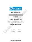
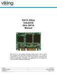
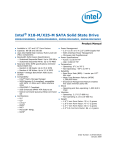
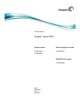
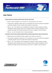
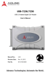
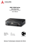
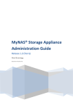
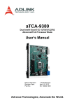
ASDHS-MLC C2 Series
Half-Slim (JEDEC MO-297)
SATA 6 Gb/s Solid State Drive
Specification
Manual Rev.:
Revision Date:
Part Number:
1.00
June 4, 2012
50-1Z129-1000
Advance Technologies; Automate the World.
Document History
2
Revision
Date
1.00
2012/06/04
Changes
Initial Release
Specification
Copyright 2012 ADLINK Technology, Inc.
Disclaimer
The information in this document is subject to change without prior notice in order to improve
reliability, design, and function and does not represent a commitment on the part of the
manufacturer. In no event will the manufacturer be liable for direct, indirect, special, incidental,
or consequential damages arising out of the use or inability to use the product or documentation,
even if advised of the possibility of such damages.
This document contains proprietary information protected by copyright.
All rights are reserved. No part of this datasheet may be reproduced by any mechanical, electronic,
or other means in any form without prior written permission of ADLINK Technology, Inc.
Specification
3
Table of Contents
4
1
Introduction .........................................................................5
1.1
1.2
1.3
1.4
1.5
1.6
1.7
Overview................................................................................................. 5
Product Specification................................................................................... 5
Functional Block Diagram ............................................................................10
Product Images ........................................................................................10
Mechanical Drawing: Compatible with JEDEC MO-297 ( w/o case ) ...........................11
Architecture ............................................................................................12
Hot Plug Support ......................................................................................12
2
Pin Locations and Signal Descriptions .................................13
2.1
2.2
Pin Locations...........................................................................................13
Signal Descriptions....................................................................................13
3
ATA Command Sets ............................................................15
3.1
3.2
3.3
3.4
3.5
3.6
3.7
3.8
ATA Command ........................................................................................15
Power Management Command Set.................................................................19
Security Mode Feature Set...........................................................................19
SMART Command Set ...............................................................................19
Host Protected Area Command Set.................................................................20
48-Bit Address Command Set .......................................................................21
Device Configuration Overlay Command Set ......................................................21
General Purpose log Command Set ................................................................21
4
SATA Command Sets...........................................................22
4.1
SATA Command.......................................................................................22
5
References..........................................................................23
6
Getting Service ...................................................................24
Specification
1 Introduction
1.1
Overview
The ASDHS-MLC64G Half-Slim SATA 6 Gb/s MLC Solid State Drive (SSD) delivers leading performance a JEDEC
MO-297 Half-Slim form factor while simultaneously improving system responsiveness for mobile applications
over standard rotating drive media or hard disk drives. By combining leading NAND flash memory technology
with our innovative high performance firmware, ADLINK delivers a SSD for native Serial Advanced Technology
Attachment (SATA) hard disk drive drop-in replacement with enhanced performance, reliability, ruggedness and
power savings, since there are no rotating platters, moving heads, fragile actuators, or unnecessary delays due
to spin-up time or positional seek time that can slow down the storage subsystem significantly I/O and
throughput performance improvement as compared to rotating media or hard disk drives. This document
describes the specifications of the ASDHS-MLC64G Half-Slim SATA 6 Gb/s MLC SSD in Half-Slim (JEDEC MO-297)
form factor.
The ASDHS-MLC64G Half-Slim SATA 6 Gb/s MLC SSD primarily targets SATA based laptop PCs, highly rugged
mobile client devices, as well as thin and light, mini/sub-notebooks. Key attributes include high performance,
low power, increased system responsiveness, high reliability, and enhanced ruggedness as compared to
standard mobile SATA hard drives. The ASDHS-MLC64G Half-Slim SATA 6 Gb/s MLC SSD is available in 2.5" and
Half-Slim form factors that are electrically, mechanically, and software compatible with existing 2.5” Serial ATA
slots and cables. Our flexible design allows interchangeability with existing mobile hard drive based on the SATA
interface standard.
1.2
Product Specification
1.2.1. Form Factor: Available in 2.5” and Half-Slim (JEDEC MO-297) SSD form factor
1.2.2. Capacity: 64GB (ASDHS-MLC64G-C2 )
Unformatted capacity
64GB
Total user addressable sectors
in LBA mode
125,045,424
Table 1: User Addressable Sectors
Notes: 1. 1GB=1,000,000,000 bytes and not all of the memory can be used for storage.
2. 1 Sector = 512 bytes
1.2.3. Flash: Multi-Level Cell (MLC) component with Toggle-Mode (24nm )
Specification
5
1.2.4. Bandwidth Performance (CrystalDiskMark)
Access Type
MB/s
Sequential Read
Sequential Write
Up to 350 (SATA 6 Gb/s, Secondary)
Up to 170 (SATA 6 Gb/s, Secondary)
Table 2: Maximum Sustained Read and Write Bandwidth
Notes: 1). Performance measured using CrystalDiskMark.
2). 1 MB/sec = 1,048,576 bytes/sec is used in measuring sequential performance. If
1 MB/sec = 1,000,000 bytes/sec is used, performance values become 4.85% higher.
1.2.5. Read and Write IOPS (IOMETER)
Access Type
IOPS
4K Read (IOPS)
4K Write (IOPS)
48,000 (SATA 6 Gb/s, Secondary)
38,000 (SATA 6 Gb/s, Secondary)
Table 3: Random Read/Write Input/Output Operations per Second
Notes: 1. Performance measured using IOMETER Pro with queue depth set to 32
2. Write cache enabled
3. Test computer: Dell E6400 (SATA 3 Gb/s - Win7 x64) and Sandy Bridge (SATA 6 Gb/s –
Win7 x64)
1.2.6. Power on to ready:
Type
Average Latency
Power on to Ready
1s
Table 4: Latency Specifications
Notes: 1. Write cache enabled
2. Device measured using Drive Master
3. Power on to ready time assumes proper shutdown
(Power removal preceded by STANDBY command)
6
Specification
1.2.7. Compatibility
-- SATA Revision 3.0 compliant
Compatible with SATA 1.5Gb/s, 3Gb/s & 6Gb/s interface rates
-- ATA/ATAPI- 8 compliant
-- SSD enhanced SMART ATA feature set
-- Native Command Queuing (NCQ) command set
-- TRIM supported
1.2.8. Certifications
Certification
CE compliant
UL certified
BSMI
Description
Indicates conformity with the essential health and safety requirements
set out in European Directives Low voltage Directive and EMC Directive
Underwriters Laboratories, Inc. Component Recognition UL60950-1
Compliance to the Taiwan EMC standard “Limits and methods of Radio
Disturbance Characteristics of Information Technology Equipment, CNS
13438 Class B”
Microsoft WHQL Microsoft Windows Hardware Quality Labs
RoHS compliant Restriction of Hazardous Substance Directive
Table 6: Device Certifications
1.2.9. Power Management
-- 5V SATA
-- SATA interface power management
-- OS-aware hot plug/removal
1.2.10. Power consumption
Description
Operating voltage for 5V (+/- 5%)
Min
4.75
Max
5.25
Unit
V
Table 7: Operating Voltage
Mode
Active (average)
Type
2.8
Unit
W
Idle (average)
0.7
W
Table 8: Typical Power Consumption
Note: Active power is measured using IOMETER Power Consumption using Data Logger _No DIPM
Specification
7
1.2.11. Temperature
Environment
Ambient Temperature
Humidity
Mode
Operating
Min
0
Non-operating
Type
Max
70
Unit
°C
-40
85
°C
Operation
5
95
%
Non-operation
5
95
%
Table 9: Temperature Relative Specifications
Note: Measured without condensation
1.2.12. Reliability
Parameter
Mean Time between Failure (MTBF)
Value
1,500,000 hours
Power on/off cycles
50000 cycles
Table 10: Reliability Specifications
1.2.14. Shock and Vibration:
Item
Shock1
Vibration2
Mode
Non-operating
Timing/Frequency
At 1 msec
Max
1500G
Non-operating
At 2 msec
1000G
Operation
7~800 Hz
2.17Grms
Non-operation
7~800 Hz
3.08Grms
Table11: Shock and Vibration
Notes:
1. Shock specifications assume that the SSD is mounted securely with the input vibration
applied to the drive mounting screws. Stimulus may be applied in the X, Y or Z axis
2. Vibration specifications assume that the SSD is mounted securely with the input
vibration applied to the drive mounting screws. Stimulus may be applied in the X, Y or Z
axis. The measured specification is in root mean squared form.
8
Specification
1.2.15. Electromagnetic Immunity
Electromagnetic Immunity tests assume the SSD is properly installed in the representative host system. The
drive operates properly without errors degradation in performance when subjected to radio frequency (RF)
environments defined in the following table.
Test
Description
Electrostatic discharge
Electrostatic discharge
Electrostatic discharge
Radiated RF immunity
Electrical fast transient
Contact ±4KV
Air: ±8KV
Contact ±6KV
Air: ±12KV
Contact ±8KV
Air: ±15KV
80~1000MHz, 3V/m,
80% AM with 1 KHz sine
900 MHz, 3 V/m, 50%
pulse modulation at
200Hz
±1KV on AC mains
±0.5KV on external I/O
±1KV differential ±2KV
common, AC mains
150KHz~80 MHz, 3 Vrms,
Conducted RF immunity
80% AM with 1KHz sine
Power frequency
50Hz, 1A/m (r.m.s)
magnetic filed
Surge immunity
Performance criteria Reference standard
A
IEC 61000-4-2:2008
B
IEC 61000-4-2:2008
C
IEC 61000-4-2:2008
A
IEC 61000-4-3:2008
B
IEC 61000-4-4:2004
+Corr.1:2006
+Corr.2:2007
B
IEC 61000-4-5:2008
A
IEC 61000-4-6:2008
A
IEC 61000-4-6:2008
Table 12: Radio Frequency Specifications
Notes:
1. Performance criterion A = The device shall continue to operate as intended, i.e.,
normal unit operation with no degradation of performance.
2. Performance criterion B = The device shall continue to operate as intended after
completion of test, however, during the test, some degradation of performance is
allowed as long as there is no data loss operator intervention to restore device
function.
3. Performance criterion C = Temporary loss of function is allowed. Operator
intervention is acceptable to restore device function.
4. Contact electrostatic discharge is applied to drive enclosure.
1.2.16. Weight: 10 g Max
1.2.17. Dimension: 39.0 x 54.0 x 4 mm (L x W x H)
1.2.18. Part Numbers:
Product Name
ASDHS-MLC64G-C2
Specification
Part No.
92-99060-7010
9
1.3
Functional Block Diagram
DDR3
DRAM
SATA
Host
Interface
1.4
Flash Memory
Controller
NAND
Flash
Array
Product Images
1.4.1. Half-Slim SATA SSD
10
Specification
1.5
Mechanical Drawing: Compatible with JEDEC MO-297 ( w/o case )
Dimensions in mm.: 39.0 x 54.0 x 4 mm (L x W x H)
Specification
11
1.6
Architecture
The ASDHS-MLC64G Half-Slim SATA 6 Gb/s Solid State Drive (SSD) utilizes a cost effective system-on-chip
(SoC) design to manage a full SATA 6 Gb/s bandwidth with the host while managing multiple flash memory
devices on multiple channels internally.
1.7
Hot Plug Support
Hot Plug insertion and removal are supported when the correct connector and an appropriate operating
system (OS) are used as described in the SATA 3.0 Specification. This product supports asynchronous signal
recovery and will establish communications with a host system without hardware device detection by
issuing an unsolicited COMINIT when first mated with a powered connector.
12
Specification
2 Pin Locations and Signal Descriptions
2.1
Pin Locations
The data and power connector pin locations of the ASDHS-MLC64G Half-Slim SATA 6 Gb/s SSD are as shown
below.
2.2
Signal Descriptions
Data Connector:
Name
S1
Type
GND
S2
A+
S3
A-
S4
GND
S5
B-
S6
B+
S7
GND
Description
Differential Signal Pair A
Differential Signal Pair B
Table 13: Serial ATA Data Connector Pin Definitions
Specification
13
Power Connector:
Name
P1
Type
V33
Description
3.3V Power
P2
V33
3.3V Power
P3
V33
3.3V Power, Pre-change
P4
GND
P5
GND
P6
GND
P7
V5
5V Power, Pre-change
P8
V5
5V Power
P9
V5
5V Power
P10
GND
P11
DAS/DSS
P12
GND
P13
V12
12V Power, Pre-change
P14
V12
12V Power
P15
V12
12V Power
Device Activity Signal / Disable Staggered
Spinup
Table 14: Serial ATA Power Connector Pin Definitions
Note:
1. All pins are in a signal row, with a 1.27mm (0.05”) pitch
2. Pins P1, P2 and P3 are connected together, although they are not connected internally to
the device. The host may put 3.3v on these pins.
3. The mating sequence is
- The ground pins P4-P6, P10, P12 and the 5V power pin P7
- The signal pins and the rest of the 5V power pins P8-P9
4. Ground connectors P4 and P12 may contact before the other 1st mate pins in both the
power and signal connectors to discharge ESD in a suitably configured backplane connector.
5. Power pins P7, P8 and P9 are internally connected to one another within the device.
6. The host may ground P11 if it is not used for Device Activity Signal (DAS)
7. Pins P13, P14, P15 are connected together, although they are not connected internally to
the device.
14
Specification
3 ATA Command Sets
3.1
ATA Command
The ASDHS-MLC64G Half-Slim SATA 6 Gb/s SSD supports all the mandatory ATA commands defined in the
ATA/ATAPI-8 specification.
3.1.1. ATA General Feature Command Set
The ASDHS-MLC64G Half-Slim SATA 6 Gb/s SSD supports the ATA General feature Command set (nonpacket), which consists of
.EXECUTE DEVICE DIAGNOSTIC
.FLUSH CACHE
.IDENTIFY DEVICE
.READ DMA
.READ SECTOR(S)
.READ VERIFY SECTORS(S)
.SEEK
.SET FEATURES
.WRITE DMA
.WRITE SECTOR(S)
.READ MULTIPLE
.SET MULTIPLE MODE
.WRITE MULTIPLE
The ASDHS-MLC64G Half-Slim SATA 6 Gb/s SSD supports all the following optional commands
.READ BUFFER
.WRITE BUFFER
.NOP
.DOWNLOAD MICROCODE
Specification
15
3.1.2. Identify Device Data
The following table details the sector data returned after issuing an IDENTIFY DEVICE command.
16
Word
F=Fixed
V=Variable
X=Both
Default Value
0
F
0040h
1
2
3
4-5
X
V
X
X
3FFFh
C837h
0010h
0h
6
X
003Fh
7-8
V
0h
9
10-19
20-21
22
23-26
27-46
X
F
X
X
F
F
0h
varies
0h
0h
varies
varies
47
F
8010h
48
49
50
51-52
53
F
F
F
X
F
0h
2F00h
4000h
0h
0007h
54
X
3FFFh
55
X
0010h
56
X
003Fh
57-58
X
00FBFC10h
59
F
0101h
60-62
63
64
65
F
F
125,045,424
(64GB)
0007h
0003h
66
F
0078h
67
F
0078h
68
F
0078h
69-70
F
0078h
F
Description
General configuration bit-significant
information
Obsolete-Number of logical cylinders (16,383)
Specific configuration
Obsolete-Number of logical heads (16)
Retired
Obsolete-Number of logical sectors per logical
track (63)
Reserved for assignment by the Compact
Flash Association
Retired
Serial number (20 ASCII characters)
Retired
Obsolete
Firmware revision (8 ASCII characters)
Model number
7:0 – Maximum number of sectors transferred
per interrupt on multiple commands
Reserved
Capabilities
Capabilities
Obsolete
Words 88 and 70:64 valid
Obsolete - Number of logical cylinders
(16,383)
Obsolete - Number of logical heads (16)
Obsolete - Number of logical sectors per
logical track (63)
Obsolete
Number of sectors transferred per interrupt
on multiple commands
Total number of user addressable sectors
Multi-word DMA modes supported/selected
PIO modes supported
Minimum multiword DMA transfer cycle time
per word
Manufacture’s recommended multiword
DMA transfer cycle time
Minimum PIO transfer cycle time without flow
control
Minimum PIO transfer cycle time with IORDY
flow control
Specification
Specification
Word
F=Fixed
V=Variable
X=Both
Default Value
71-74
F
0h
75
F
0h
76
77
78
79
80
81
82
83
84
85
86
87
88
89
F
F
F
F
V
F
F
F
F
F
V
V
V
V
001Eh
0106h
0h
0048h
0040h
00FCh
001Ah
746Bh
7C01h
6123h
7469h
BC01h
6123h
407Fh
90
F
0001h
91
F
0001h
92
93
V
V
0h
0FFFEh
94
F
0h
95
V
0h
96
97
98-99
100-103
104
105
106
107
108-111
F
V
V
F
V
F
F
0h
0h
0h
0h
125,045,424
(64GB)
0h
0h
4000h
112-115
F
0h
116
F
varies
117-118
F
0h
119
120
V
F
0h
0h
V
Description
Reserved (for future command overlap and
queuing)
Reserved for the IDENTIFY packet DEVICE
command
Queue depth
Serial ATA capabilities
Reserved for future Serial ATA definition
Serial ATA features supported
Serial ATA features enabled
Major Version Number
Minor Version Number
Command set supported
Command sets supported
Command set /feature supported extension
Command set /feature enabled
Command set /feature enabled
Command set /feature default
Ultra DMA modes
Time required for security erase unit
completion
Time required for enhanced security erase
completion
Current advanced power management value
Master Password Revision Code
Hardware reset result. The contents of bits
(12:0) of this word shall change only during
the execution of a hardware reset.
Vendor’s recommended and actual acoustic
management value
Stream Minimum Request Size
Streaming Transfer Time - DMA
Streaming Access Latency - DMA and PIO
Streaming Performance Granularity
Maximum user LBA for 48-bit Address feature
set
Streaming Transfer Time - PIO
Reserved
Physical sector size/logical sector size
Inter-seek delay for ISO-7779 acoustic testing
in microseconds
Unique ID
Reserved for word wide name extension to
128 bits
Reserved for technical report
Words per logical sector
17
Word
F=Fixed
V=Variable
X=Both
Default Value
Description
121-126
127
128
F
F
F
401Ch
401Ch
0h
129-159
F
0h
160
161-175
V
X
0021h
0h
176-205
F
0h
206-216
217
218-221
222
223-233
234
235
236-254
255
236-254
255
X
V
F
F
F
F
F
0h
0h
0h
0001h
0h
101F
0h
0001h
02A0h
0h
varies
Supported settings
Command set/feature enabled/Supported
Reserved
Removable Media Status Notification feature
set support
Security status
Vendor specific
Compact Flash Association (CFA) power mode
1
Reserved for assignment by the CFA
Current media serial number
Reserved
Non-rotating media device
Reserved
Reserved
Reserved
Reserved
Reserved
Reserved
Integrity word (checksum and signature)
F
X
Table 15: Returned Sector Data
Notes:
1.
F=Fixed. The content of the word is fixed and does not change for removable media devices,
these values may change when media is Removed or changed.
2.
V=Variable. The state of at least one bit in a word is variable and may change depending on
the state of the device or the commands executed by the device.
3.
18
X=F or V. The content of the word may be fixed or variable.
Specification
3.2
Power Management Command Set
The ASDHS-MLC64G Half-Slim SATA 6 Gb/s SSD supports the power management command set, which
consists of
.CHECK POWER MODE
.IDLE
.IDLE IMMEDIATE
.SLEEP
.STANDBY
.STANDBY IMMEDIATE
3.3
Security Mode Feature Set
The ASDHS-MLC64G Half-Slim SATA 6 Gb/s SSD supports the Security Mode command set, which consist of
.SECURITY SET PASSWORD
.SECURITY UNLOCK
.SECURITY ERASE PREPARE
.SECURITY ERASE UNIT
.SECURITY FREEZE LOCK
.SECURITY DISABLE PASSWORD
3.4
SMART Command Set
The ASDHS-MLC64G SATA SSD supports the SMART command set, which consist of
.SMART ENABLE OPERATIONS
.SMART DISABLE OPERATIONS
.SMART ENABLE/DISABLE AUTOSAVE
.SMART RETURN STATUS
The ASDHS-MLC64G Half-Slim SATA 6 Gb/s SSD supports the the following optional commands.
.SMART EXECUTE OFF-LINE IMMEDIATE
.SMART READ DATA
.SMART READ LOG
.SMART WRITE LOG
Specification
19
The table below lists the SMART commands.
Subcommand
Code
SMART ATTRIBUTE VALUES (READ DATA)
D0h
READ ATTRIBUTE THRESHOLDS
D1h
ENABLE/DISABLE ATTRIBUTE AUTOSAVE
D2h
SAVE ATTRIBUTE VALUES
D3h
EXECUTE OFF-LINE IMMEDIATE
D4h
LBA Low value
EXECUTE SMART OFF-LINE ROUTINE
00h
EXECUTE SMART SHORT SELF-TEST ROUTINE (OFFLINE)
01h
EXECUTE SMART EXTENDED SELF-TEST ROUTINE (OFFLINE)
02h
ABORT OFF-LINE ROUTINE
7Fh
EXECUTE SMART SHORT SELF-TEST ROUTINE (CAPTIVE)
81h
EXECUTE SMART EXTENDED SELF-TEST ROUTINE ( CAPTIVE )
82h
READ LOG SECTOR
D5h
WRITE LOG SECTOR
D6h
ENABLE SMART OPERATIONS
D8h
DISABLE SMART OPERATIONS
D9h
RETURN SMART STATUS
DAh
Table 16: SMART commands
3.5
Host Protected Area Command Set
The ASDHS-MLC64G Half-Slim SATA 6 Gb/s SSD supports the Host Protected Area command set which
consists of
.READ NATIVE MAX ADDRESS
.SET MAX ADDRESS
.READ NATIVE MAX ADDRESS EXT
.SET MAX ADDRESS EXT
The ASDHS-MLC64G Half-Slim SATA 6 Gb/s SSD supports the following optional commands.
.SET MAX SET PASSWORD
.SET MAX LOCK
.SET MAX FREEZE LOCK
.SET MAX UNLOCK
20
Specification
3.6
48-Bit Address Command Set
The ASDHS-MLC64G Half-Slim SATA 6 Gb/s SSD supports the Host Protected Area command set, which
consists of
.READ NATIVE MAX ADDRESS
.FLUSH CACHE EXT
.READ DMA EXT
.READ NATIVE MAX ADDRESS EXT
.READ SECTOR(S) EXT
.READ VERIFY SECTOR(S) EXT
.SET MAX ADDRESS EXT
.WRITE DMA EXT
.WRITE MULTIPLE EXT
.WRITE SECTOR(S) EXT
3.7
Device Configuration Overlay Command Set
The ASDHS-MLC64G Half-Slim SATA 6 Gb/s SSD supports the Device configuration Overlay command set,
which consists of
.DEVICE CONFIGURATION FREEZE LOCK
.DEVICE CONFIGURATION IDENTITY
.DEVICE CONFIGURATION RESTORE
.DEVICE CONFIGURATION SET
3.8
General Purpose log Command Set
The ASDHS-MLC64G Half-Slim SATA 6 Gb/s SSD supports the general purpose log command set, which
consists of
.READ LOG EXT
.WRITE LOG EXT
Specification
21
4 SATA Command Sets
4.1
SATA Command
The SATA 3.0 specification is a super set of the ATA/ATAPI-8 specification with regard to supported
commands. The ASDHS-MLC64G Half-Slim SATA 6 Gb/s SSD supports the following features which are
unique to SATA Specification.
4.1.1. Software Settings Preservation
The ASDHS-MLC64G Half-Slim SATA 6 Gb/s SSD supports the SET FEATURES parameter to enable/disable
the preservation of software settings.
4.1.2. Native Command Queuing
The ASDHS-MLC64G Half-Slim SATA 6 Gb/s SSD supports the Native Command Queuing (NCQ) command
set, which includes.
.READ FPDMA QUEUED
.WRITE FPDMA QUEUED
Note: with a maximum queue depth equal to 31
22
Specification
5 References
This document references standards defined by a variety of organizations use the following list to identify the
location of an organization’s standards information.
Date
Title
Location
http://www.vcci.or.jp/vcci_e/general/
join/index.html
Dec 2008
VCCI
July 2007
ROHS
Search for material description datasheet
at http://intel.pcnalert.com
July 2007
SFF-8144, 1.8” drive form factor
http://www.sffcommittee.org
February 2007
Serial ATA Revision 2.6
http://www.sata-io.org
May 2006
SFF-8223, 2.5” Drive w/Serial Attachment Connector
http://www.sffcommittee.org
May 2005
SFF-8201, 2.5” drive form factor
http://www.sffcommittee.org
April 2004
ATA-7 Spec. Volume 1
http://www.t13.org/
Aug. 2009
ATA-8 Spec. Rev 2
http://www.t13.org/
International Electro Technical Commission EB61000
1995
4-2 Personnel Electrostatic Discharge Immunity
1996
4-3 Electromagnetic compatibility (EMC)
1995
4-4 Electromagnetic compatibility (EMC)
1995
4-5 Electromagnetic compatibility (EMC)
1997
4-6Electromagnetic compatibility (EMC)
1994
4-11 (Voltage variations)
1995
ENV 50204 (Radiated electromagnetic field from
digital radio telephones)
http://www.iec.ch
http://www.iec.ch
Table 17: Standards References
Specification
23
6 Getting Service
Contact us should you require any service or assistance.
ADLINK Technology, Inc.
Address: 9F, No.166 Jian Yi Road, Zhonghe District
New Taipei City 235, Taiwan
新北市中和區建一路 166 號 9 樓
Tel:
+886-2-8226-5877
Fax:
+886-2-8226-5717
Email:
[email protected]
Ampro ADLINK Technology, Inc.
Address: 5215 Hellyer Avenue, #110, San Jose, CA 95138, USA
Tel:
+1-408-360-0200
Toll Free: +1-800-966-5200 (USA only)
Fax:
+1-408-360-0222
Email:
[email protected]
ADLINK Technology (China) Co., Ltd.
Address: 上海市浦东新区张江高科技园区芳春路 300 号 (201203)
300 Fang Chun Rd., Zhangjiang Hi-Tech Park,
Pudong New Area, Shanghai, 201203 China
Tel:
+86-21-5132-8988
Fax:
+86-21-5132-3588
Email:
[email protected]
ADLINK Technology Beijing
Address: 北京市海淀区上地东路 1 号盈创动力大厦 E 座 801 室(100085)
Rm. 801, Power Creative E, No. 1, B/D
Shang Di East Rd., Beijing, 100085 China
Tel:
+86-10-5885-8666
Fax:
+86-10-5885-8625
Email:
[email protected]
ADLINK Technology Shenzhen
Address: 深圳市南山区科技园南区高新南七道 数字技术园 A1 栋 2 楼 C 区 (518057)
2F, C Block, Bldg. A1, Cyber-Tech Zone, Gao Xin Ave. Sec. 7,
High-Tech Industrial Park S., Shenzhen, 518054 China
Tel:
+86-755-2643-4858
Fax:
+86-755-2664-6353
Email:
[email protected]
24
Specification
LiPPERT ADLINK Technology GmbH
Address: Hans-Thoma-Strasse 11, D-68163, Mannheim, Germany
Tel:
+49-621-43214-0
Fax:
+49-621 43214-30
Email:
[email protected]
ADLINK Technology, Inc. (French Liaison Office)
Address: 15 rue Emile Baudot, 91300 Massy CEDEX, France
Tel:
+33 (0) 1 60 12 35 66
Fax:
+33 (0) 1 60 12 35 66
Email:
[email protected]
ADLINK Technology Japan Corporation
Address: 〒101-0045 東京都千代田区神田鍛冶町 3-7-4
神田 374 ビル 4F
KANDA374 Bldg. 4F, 3-7-4 Kanda Kajicho,
Chiyoda-ku, Tokyo 101-0045, Japan
Tel:
+81-3-4455-3722
Fax:
+81-3-5209-6013
Email:
[email protected]
ADLINK Technology, Inc. (Korean Liaison Office)
Address: 서울시 서초구 서초동 1675-12 모인터빌딩 8 층
8F Mointer B/D,1675-12, Seocho-Dong, Seocho-Gu,
Seoul 137-070, Korea
Tel:
+82-2-2057-0565
Fax:
+82-2-2057-0563
Email:
[email protected]
ADLINK Technology Singapore Pte. Ltd.
Address: 84 Genting Lane #07-02A, Cityneon Design Centre,
Singapore 349584
Tel:
+65-6844-2261
Fax:
+65-6844-2263
Email:
[email protected]
ADLINK Technology Singapore Pte. Ltd. (Indian Liaison Office)
Address: 1st Floor, #50-56 (Between 16th/17th Cross) Margosa Plaza,
Margosa Main Road, Malleswaram, Bangalore-560055, India
Tel:
+91-80-65605817, +91-80-42246107
Fax:
+91-80-23464606
Email:
[email protected]
Specification
25