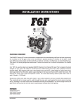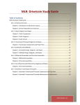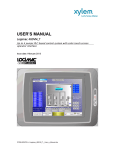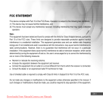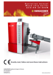
1
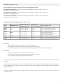
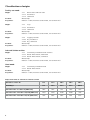
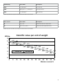
PELLET AND WOOD CHIP HEATING Planning Portfolio Wood chips heating systems 50–150 kW Efficient Innovative Quality Know-how CO2-neutral DIE ZUKUNFT DESSustainable HEIZENS PLANNING PORTFOLI0 Wood chips heating systems 35 - 150 kW T H E F U T U RE O F H E AT I N G Only start-up the heating system after having read this assembly instruction thoroughly! 06/2011 ENG 940000191303 / EN / 36s / V1.0 Contents 01Overview 1.1 Safety notice 1.2 Servicing note 1.3 Boiler Temperature 1.4 Chimney Presetting 1.4.1 Effective height 1.5 What are the small pieces of wood, commonly called wood chips? 1.6 Which wood chips to use 4 4 4 4 5 5 6 7 02 Wood Chip Storage 2.1 Configuration of wood chips depot 10 11 03 Detailed design guide 12 04 Heating system description – wood chips system 13 05 Microprocessor controlled adjustment 14 06 Technical data 15 07 Description wood chip boiler 7.1 Details of wood chip boiler HZ50 7.2 Overall dimensions HZ50 7.3 Details of wood chip boiler HZ150 / HZ100 7.4 Overall dimensions HZ150 / HZ100 17 17 18 19 20 08 Feeding / Transport technique 8.1 Description / Details about the feeding technique 8.2 Description / Details about the transport system 8.3 Description / Details about the auger feeding system 8.4 Stoker system 21 21 21 21 21 09 Boiler cross section 22 10 Operation Safety 23 11 Design example 25 12 Hydraulic diagrams 32 3 01 Overview Buildings requiring a high level of security of heat supply (hotels, process heat, etc.) should operate a double boiler system. In the case of non-compliance, we reject all damage claims arising due to lack of heat supply. Owing to their design, biomass heating systems require appropriate support (by the caretaker, janitor, etc) so that the prescribed maintenance tasks are carried out regularly. Please note that the prescribed maintenance intervals must be observed during the guarantee period. In the case of large variations in the fuel material, the combustion controller should be reset by the customer service team with each refilling. The heating system should be designed so that 50% of the boiler system output can be withdrawn for a period of at least 2 hours. 1.1 Safety notice Based on the guidelines applicable in Austria for preventive fire protection, TRVB H 118 appliances need controlled servicing routines weekly, monthly and annually. Refer to the HZ inspection manual, which is available for downloading on our home page. 1.2 Servicing note Servicing to the HZ inspection manual Servicing is to be performed weekly according to the inspection manual. The boiler is fitted with an automatic heat exchanger cleaning unit. The flue and the top flue gas collector (remove the boiler cover on the top) must be cleaned several times a year, depending on the installation situation and wood chip quality. Follow the cleaning instructions! Annual service: The system must be inspected, cleaned and reset once a year by a qualified technician. We will try to arrange this for you with our company or put you in touch with our contractual partner. Any warranty obligation lapses if unauthorized modifications and changes to the heating system are made. Warranty: 5 years for heat exchanger sealing 3 years for the boiler and steel structures (excluding parts subject to fair wear and tear) 2 years for electrical equipment 1.3 Boiler Temperature The boiler should reach a temperature of at least 70 degrees Celsius. If this temperature is not reached, the boiler must be cleaned. An even flushing of the boiler can be achieved and corrosion of the internal walls of the boiler prevented by setting the return flow temperature increase to 60 degrees Celsius. Note: In the event of malfunction of the return flow temperature increase (return flow temperature not always above 55°C during normal operation) the warranty is voided. 4 1.4 Chimney Presetting A moisture resistant (MS) chimney with a (Recommendation material 1.4401, 1.4404) maximum chimney draught of 30 Pa (0.30 mbar) is required, depending on the system. The connection line (flue connector) must be installed with at least 10° of inclination (30-45° is optimum) with a maximum length of 3.0 metres. The flue connector must be insulated with at least 25 mm. Execute the chimney connection using at least 45° elbows. Flue gas problems can occur if 90° elbows are used in a connection. Incorporation of the flue gas connector in the chimney must be done so that no condensation water can flow into the boiler. The heating boiler and the chimney must be coordinated with each other (see the chimney recommendation). Please use EN 13384-1 as an aid in calculations. The chimney must be moisture resistant (MS)! Installation of a draught stabilizer is required. System Type HZ 50 HZ 100 HZ 150 Required delivery head - MIN (mbar / Pa) 0,1 / 10 0,15 / 15 Required delivery head - MAX (mbar / Pa) 0,3 / 30 0,3 / 30 200 250 / 300 EN 13384-1 EN 13384-1 Chimney diameter (mm) 600 mm Chimney computation according to standard ≤10 ° (30–45°) Requirements for the flue connector Connect the flue connector rising on the chimney at least 10°, ideally 30 to 45° The flue connector must not be reduced; the diameter of the flue connector must correspond to that of the flue sockets. The flue connector must be a pressure-tight design and provided over its entire length with at least 25 mm thick thermal insulation. The draught regulator must be installed at least 600 mm below the flue connector inlet in the flue system. ATTENTION: If, due to local conditions, the chimney draught regulator is deployed directly in the flue duct as opposed to the position recommended below, an increased dust load must be expected in the heating room - PLEASE note this at the time of planning! 1.4.1 Effective height The effective height is the chimney length between the flue inlet in the chimney and the chimney mouth. The chimney must be adapted to the local, regulatory specifications! Low-emissions operation in accordance with the Quality seal is possible only if the system can be operated using the low flue gas temperatures of the lowest heat output (30% of rated load). As a rule, this requires an acid-resistant chimney. 5 1.5 What are the small pieces of wood, commonly called wood chips? Wood chips are mechanically crumbled pieces of wood used to feed automatic wood burning systems. Wood chips may have different origin. We can distinguish among: wood chips from forest fresh wood, wood chips from sawmill rejects, from trees cut down to re-design the landscape, from treated or untreated recycled wood, and from intensive specialized growing wood. The wood chips heating systems are cost effective for energy requirements starting from 20 kW; this means that they are particularly suitable for large buildings. However, small wood chips up to 3 cm are ideal also for small heating systems, while coarse wood chips are often used for district heating plants. The wood chips are produced using a variety of processes and machinery. The production process is often dictated by the type of wood being handled (i.e. timber trunks are processed differently from branches and smaller round wood). Depending on the size of wood chips to be produced, various types of high speed and low speed shredding machines can be used. The shredding machines are based upon different manufacturing technologies, namely: disk, drum and auger based machines. The quality and storage property of wood chips is strongly affected by the water content. Fresh forest wood typically has a water content of about 40%, providing that the wood is cut down and left seasoned for 6 months prior to be chipped. The wood chips should then be submitted to a predrying process in order to reduce the moisture degree below 40%. Infact, when burning wood chips not sufficiently dried, part of the energy is used for moisture evaporation, thus reducing the calorific value of the fuel. The drying also reduces the build up of potential harmful spores during the subsequent storage. In addition, the dry wood chips require much less storage room. The wood chip measuring unit is the bulk stere meter (srm) or cubit meter which corresponds to about 200 – 300 kg depending on the size, moisture degree and type of wood. With a residual moisture of 40%, the calorific value ranges between 2.5 and 4.0 GJ/srm. Wood chips are made of 100 % wood. They have a calorific value of around 4.0 kWh (= 14.4 MJ) per kg (depending on the type of wood, at a moisture content of approx. 20 %) and can be fed automatically into wood chip burners by means of conveyors with spring blade fuel extractors. Moisture content: There are several key properties of wood chips which vary depending on the species of tree and which affect the calorific value. This applies particularly to the moisture content, which has a significant impact on the calorific value of wood chips and affects their suitability for storage. Wood chips with a moisture content of less than 30 % are „suitable for storage“ and do not usually experience significant microbial decomposition. However, green wood chips have a moisture content of 50 to 60 %. Freshly cut softwood has a calorific value of around 2 kWh/kg, while a moisture content of 20 % results in double the calorific value, at around 4 kWh/kg. Size and size distribution: Other properties include the size and size distribution and the bulk density of the wood chips and the energy density as fuel as well as the amount of space required for transportation and storage. Oak and beech wood, which are very dense (571 and 668 kg dry weight [DW] / cubic metre [m³] respectively), have a calorific value of around 1100 kWh/ bulk-stacked cubic metre with a moisture content of 20%, whereas less dense poplar wood (353 kg dry weight [DW] / cubic metre [m³] ) has a calorific value of only 680 kWh/bulk-stacked cubic metre for the same moisture content. Proportion of bark: The proportion of bark also influences the quality of wood chips. Wood chips for use as fuel in smaller wood chip burners are normally made from debarked wood, while the cheaper bark wood chips contain higher proportions of bark. They are produced mainly from logging residues, small wood and other low-value wood (e.g. from thinnings, clippings from landscape maintenance). They can be used to produce particle board or for generating power in large plants such as biomass heating plants and biomass combined heat and power plants. 6 1.6 Which wood chips to use The following fuel is approved for Biotech wood chip heating systems: Wood chip boiler HZ50: wood chips according to EN 14961-1 | P16A/B - P45A / M35, A1.0; Attention: max. length 50 mm! Wood chip boiler HZ100: wood chips according to EN 14961-1 | P16A/B - P45A / M35, A1.0; Attention: max. length 50 mm! Wood chip boiler HZ150: wood chips according to EN 14961-1 | P16A/B - P45A / M35, A1.0; Attention: max. length 50 mm! Wood chips: size classes (Fine fraction < 1 mm: < 5 %) Class ÖNORM M 7133 Minimum 75-m% in main fraction, mma Fine fraction m-% (<3,15 mm) Coarse fraction, m-% P16A P16B G30 3,15 ≤ P ≤ 16 mm 3,15 ≤ P ≤ 16 mm ≤ 12 % ≤ 12 % ≤ 3 % > 16 mm and all 30 mmc ≤ 3 % > 45 mm and all 120 mmc 8 ≤ P ≤ 45 mm ≤8%b 8 ≤ P ≤ 45 mm ≤8%b 8 ≤ P ≤ 63 mm ≤6%b ≤ 6 % > 100 mm and all < 350 mm 16 ≤ P ≤ 100 mm ≤4% ≤ 6 % > 200 mm and all < 350 mm P45A G50 P45B P63 P100 G100 b ≤ 6 % > 63 mm and max. 3,5 % > 100 mm, all < 120 mm ≤ 6 % > 63 mm and max. 3,5 % > 100 mm, all < 350 mm Class: P16 • Main fraction particle size: between 3.15 mm and 16 mm. • Fine fraction: wood smaller than 3.15 mm; maximum content 12 %. • Coarse fraction particle size: greater than 16 mm for type P16A and 31.5 mm for type P16B Class: P45 • Main fraction particle size: between 8 mm and 45 mm. • Fine fraction: wood smaller than 3.15 mm; maximum content 8%. • Coarse fraction particle size: greater than 100 mm. The values (P-Class) for the dimensions refer to the particle sizes passing through a sieve as per standard prEN 15147-1t. a The main fraction for P45B is 3.15 ≤ P ≤ 45 mm, for P63 it is 3,15 ≤ P ≤ 63 mm and for P100 it is 3,15 ≤P ≤ 100 mm and in addition, the fine fraction should not exceed 25-w% if the raw material is felling residues containing branches, needles or leaves. b The cross-sectional area of the oversized particles should be: for P16 <1 cm2, for P45 < 5 cm2, for P63 < 10 cm2 and for P100 < 10 cm2. c 7 Classification of origin: Freshly-cut wood: Origin: 1.1.1 Whole trees without roots 1.1.1.1 Hardwood 1.1.1.2 Softwood Product: Wood chips Properties: P16A/B – P45A, moisture content M35, ash content A1.0 Origin: 1.1.3 Logs 1.1.3.1 Hardwood 1.1.3.2 Softwood Product: Wood chips Properties: P16A/B – P45A, moisture content M35, ash content A1.0 Origin: Product: Properties: 1.1.4 Logging residues 1.1.4.3 Dry, hardwood 1.1.4.4 Dry, softwood Wood chips P16A/B – P45A, moisture content M35, ash content A1.0 Industrial timber residue: Origin: Product: Properties: 1.2.1 Chemically untreated wood residues 1.2.1.1 Wood without bark, hardwood 1.2.1.2 Wood without bark, softwood Wood chips P16A/B – P45A, moisture content M35, ash content A1.0 Used wood: Origin: Product: Properties: 1.3.1 Chemically untreated wood 1.3.1.1 Wood without bark Wood chips P16A/B – P45A, moisture content M35, ash content A1.0 Chips: heat value as a function of water content Moisture content M 0% 15 % 20 % 30 % 50 % Humidity u 0% 18 % 25 % 43 % 100 % Calorific value of softwood [kWh/srm] 840 820 815 800 730 Calorific value of hardwood (hard) [kWh/srm] 1130 1100 1090 1060 970 Calorific value of hardwood (soft) [kWh/srm] 700 690 680 665 610 8 Bulk Density Class limits Description S160 S ≤ 160 kg/m2 Low density S200 160 kg/m2 < S ≤ 200 kg/m2 Average density S250 S > 200 kg/m2 High Density Wood chip bulk density according to the Austrian norm M7133 Ash Content Class limits Description A1 A ≤ o,5 % Wood chip with low bark levels A2 0,5 % < A ≤ 2,0 % Wood chip with high bark levels Wood chip ash content according to the Austrian norm M7133 Calorific value per unit of weight kWh/kg 6 5,20 5 5,00 4 4,91 4,72 4,61 4,43 4,32 4,15 3 2 Softwood 4,02 3,86 3,73 3,58 3,44 3,30 3,14 3,01 Hardwood 2,85 2,73 2,55 2,44 2,26 2,16 1 1,97 1,88 1,67 1,59 0 0 5 10 15 20 25 30 35 40 45 50 55 60 Moisture content % 9 02 Wood Chip Storage The storage of wood chips is considerably more involved than the storage of logs. Fungi and bacteria contained in moist wood chip can lead to the generation of considerable heat. Temperatures of over 80º are not unusual and in some cases temperatures of over 100°C have been reached. At these temperatures it is possible that the wood fuel spontaneously catches fire. How much heat is generated and how quickly depends on a number of factors including moisture content, material composition, density, quantities stored, location and method of storage, contamination content, surrounding temperature, and amount of bacteria and fungi in the wood. Besides the heat generation, the fungi and bacteria development could also determinate a degradation of the fuel organic substance. In order to reduce such effect, the biological activity shall be as much as possible prevented. To this purpose, the following preventive measures should be adopted • Store the wood chips with as low moisture content as possible • Try to avoid too many needles of leaves in the fuel as this can lead to bacteria development • Store for as short a time as possible • Protect the fuel against damp (atmospheric agents) • Ensure that the storage room is well ventilated (heat and humidity dissipation) • Be careful with the height of the stacks • Try to avoid dust generation in the store • Provide active drying with ventilation, if possible The prevention of fungi build up is also important for health reasons. One of the most important contributory factor is the temperature and moisture content of the wood chips. Fungal spores also present a health hazard as they will be released in the air during loading and unloading of wood chips into the store. Spores released in the air can be inhaled and result in various side effects e.g. allergies. • The wood should be stored for six months outside before being chipped • The chips should not be stored for too long • Leaves and needles should be minimised in the chips • Dust should be kept to a minimum • The wood chips depot should be located away from residential or working areas. • The wood chips depot should not be directly located in the prevailing wind. • The chips should be burnt in the order that they were stored i.e. oldest first. • The chips storage area should be kept clean. • For outside storage, the chips should be arranged in piles with a pointed apex. • For internal storage, the chips should be arranged in a dam form (hole in the centre). • Internal storage rooms should be tall and spacious to avoid the build-up of condensation. • Internal storage rooms should provide a ventilation system. • Textiles, foodstuffs, and other materials should not be stored together with the wood chips 10 Because of their production method, the wood chips are only available as large amount bulk material. This obviously requires adequate storage spaces which are not usually available in detached houses. This is why the wood chip application is mainly suitable for large houses, farms and district heating solutions. 2.1 Configuration of wood chips depot The wood chips depot needed to the heating plant may have different configurations as shown on the examples below. The depot replenishment is usually carried out using adequate vehicles, such as a tractor. Feeding system with elevator screw Filling of the storage room using a front loader Filling of the storage room via air blower Feeding system with down-pipe Possibility of a screw channel length of over 12 m (multiple components) The above examples are merely indicative and cannot be applied 1:1 to your individual location! 11 03 Detailed design guide Purpose of application and scope of use: Units from the HZ50 to HZ 150 boiler series are intended for use with the fuel indicated in this document. The use of other fuels, or use which is not in accordance with the specifications, will invalidate the guarantee, without exception. The structural design of the systems referred to is based on an average and conventional annual time line. (The systems are operated predominantly in part-load operation, since maximum output will only be required for a few hours or days per year). If the systems are operated as base-load boilers (predominantly at rated load, or close to rated load), then a correspondingly high degree of wear and maintenance effort and expenditure are to be reckoned on. Depot size The fuel depot must be dimensioned in such a way as to reduce as much as possible the number of replenishments (max 4 per year)! As in most cases it is impossible to provide a depot with circular layout, you should at least design a squared layout depot. To calculate the annual overall consumption you may use the following empirical formula: 2 m3 of depot every kW of thermal power. Example related to an HZ50 model (wood chips system with 50 kW power): 50 kW x 2 = 100 m3 wood chips/year 3 100 m / 4 replenishments/year = 25 m3 depot volume 3 25 m / 2 m depot height = 12,5 m2 deport surface Solution: the depot layout surface shall range between 3.5 x 3.5 m and 4 x 4 m As an alternative, you may deviate from the above values up to a maximum of 1 m between length and width, e.g. 3 x 4 m Important warning: The maximum store size is 6 × 6 m, but with these dimensions the wood chips can no longer be delivered from the corners (maximum spring leaf length is 3000 mm) Our space holding is designed for a stacking height of up to 6 metres. NOTE: If the stacking height is over 6 metres, this must be inspected and approved separately. Important: With this height, during the depot replenishment, after about 1 meter, you should activate the mixer that drives the leaf springs. Through-wall path: The transport duct should not be embedded in the wall to avoid noisiness transmission to the wall itself! The spaces around the trough-wall transport duct should then be created using insulating material in compliance with the prescriptions of DIN 4102-11 norm or B 3836 Austrian norm. Tip: create the through-wall passages on inspection openings (to make easier the removal of possible jams due to an excessive length of wood chips). Side protection of walls: As in rectangular depots the leaf springs could get in contact with the wall, it is advisable to apply a hard wooden protection on the depot wall (height: 25-30 cm). This avoids damaging both: the wall and the mixer leaf springs. Recommendation: For long burner running times, in order to reduce the start-stop emissions and to reduce maintenance costs, the boiler should be fitted with a buffer storage tank, thermosiphon buffer storage tank or combination storage tank. In practice, buffer capacities between 40 and 75 litres/kW have proven successful. Be sure to take into account the country-specific requirements regarding buffer storage tanks. The operation of the system is only permissible if it can be guaranteed that the boiler‘s nominal heat output can be reduced by 50% for a period of at least 2 hours. 12 Double bottom: The double bottom prevents part of material from being jammed beneath the mixer. This structure shall be selfsupporting and shall not warp under the wood chips load. Chimney / Chimney connection: Due to the low temperature of combusted gases (high boiler yield), the chimney shall not be sensitive to humidity. During the early design stage it is kindly recommended to contact a chimney sweep specialist for a reliable installation test. An air extraction regulation device shall also be installed. The ideal installation position of such regulator is inside the chimney, beneath the outlet duct mouth of combusted gases. Water connection: In order to ensure a long life of your installation, this shall be fitted with an anticondensation circuit (55° C) as shown on the connection diagram. The mixer control of the anticondensation system is integrated within the standard regulator! 04 Heating system description – wood chips system The Biotech HZ wood chips heating system consists of: • Boiler with burner and ash discharge system • Falling step with backfire protection unit • Stoker auger, extraction auger, floor mixer with leaf springs • PLC control unit with operator panel and display. Operation: The extraction auger, directly driven by a motor located at the boiler room, moves by means of an angular countergear, the leaf spring based mixer. The wood chips fall onto the stoker auger, through the falling step where a suitable backfire protection door is installed. The fuel is then conveyed into the combustion chamber through a front thrust action and here burnt (inside a rectangular retort). The fuel replenishment is controlled by a special ember layer probe. The ash is automatically evacuated from the combustion chamber by means of a tipping grate (HZ50) or step grate (HZ100 / HZ150) fitted with ash collection boxes. The combustion fans with revolution speed adjustment device convey the primary combustion air into the burner and the secondary air above the ember layer i.e. into the post-combustion area. The hot combusted gases flow across the self-cleaning three-way pipe based thermal exchanger and release the energy needed for boiler water heating. Upstream the chimney connection, an air extraction fan with revolution speed adjustment device, a lambda probe and a combusted gas thermal probe are installed, whose values are measured and analysed thus allowing an accurate system regulation. The depression control of combustion chamber is performed by means of a pressure gauge capsule for all system types. The ignition of fuel occurs in a fully automatic way through a hot air fan. Beneath the combustion item which is connected to the thermal exchanger by means of flanges, an ash extraction auger (HZ100 / HZ150) is installed, which conveys the ash into a tank. The control unit regulates the automatic operation of the whole system. After the power-on, the fuel is conveyed into the combustion chamber and burnt by the electrical ignition device. The desired boiler temperature can be setup on the electronic control panel. The amount of fuel as well as the amount of primary and secondary air required for optimum combustion are detected and processed by the control unit using the ember layer probe, the lambda probe, the thermal probe and the depression measured value. 13 Safety devices: Safety thermostat: It switches off the whole system when the boiler temperature exceeds 90°. Backfire protection door: Integrated in the falling well, it is automatically closed at power-on, at ember keeping time and in case of faults or system power-off. Falling well: It separates the feeding auger from the stoker auger. Thermal probe: It is installed on the upper edge of stoker auger channel. When the probe detects a temperature exceeding 70° C, the backfire protection door is closed and the stoker auger content is conveyed towards the combustion chamber. 05 Microprocessor controlled adjustment The menu driven management, together with the self-explanatory texts allow the operator to avoid a continous consultation of the user manual. In addition to a perfect combustion adjustment, the lambda probe allows the user to control up to 16 heating circuits by means of external modules. The system control can be further simplified using the remote room regulator. 14 06 Technical data System type HZ50 HZ150 / HZ100 Nominal heat performance (kW) 49,00 164,00 / 99,00 Degree of efficiency at full load (%) 92,40 92,80 Degree of efficiency at part load (%) 91,80 93,80 Max. adjustable boiler temperature (C°) 85 85 Tolerable operating pressure (bar) 3 3 CE CE CE designation according to low tension guidelines Dimensions Width of boiler (mm) 754 990 Depth of boiler (mm) 1200 1 1520 1 Total depth (mm) 1280 4 2210 4 Height of boiler (mm) 1480 2 1970 2 Height of smoke tube connection (mm) 940 1730 Height of flow (mm) 1300 1800 Height of return flow (mm) 570 440 Height of ventilation (mm) 1300 1800 Diameter of smoke tube connection (mm) 200 250 / 300 Total weight (kg) 570 1350 Water content (ltr.) 145 225 Ash box - useable (ltr.) 120 150 Flow (inch) 1 1/4 2 Return flow (inch) 1 1/4 2 Ventilation for boiler (inch) n.B. n.B. Boiler emptying (inch) n.B. n.B. Connections Heating water fow resistance rT= 20 K (mbar) 5 12 rT= 10 K (mbar) 17 46 Exhaust gas temperature at full load (C°) 117,30 165 Exhaust gas temperature at part load (C°) 74,20 90 Exhaust gas mass fow at full load (g/s) 31,30 10,00 Exhaust gas values Exhaust gas mass fow at part load (g/s) 10,30 32,80 0,1 - 0,3 / 10 - 30 0,15 - 0,3 / 15 - 30 Required supply pressure at part load (mbar/Pa) 0,1 / 10 0,15 - 0,2 / 15 - 20 Burner temperature (C°) ca.1000 ca.1000 Co2 at full load (mg/m3) 11 3 53 3 Co2 at part load (mg/m3) 35 3 73 3 Nox at full load (mg/m3) 103 3 127 3 Nox at part load (mg/m3) n.B. 107 3 HC at full load (mg/m3) 13 13 HC at part load (mg/m3) 13 13 Dust at full load (mg/m³) 21 3 39 3 Dust at part load (mg/m³) n.B. 3 53 400VAC, 50Hz, 8A, max 1800W 400VAC, 50Hz, 8A, max 1800W Required supply pressure at full load (mbar/Pa) Electric power inpute Electrical recording Standby (W) 5 6 Current consumption at full load in % of full load performance 0,4 0,3 Current consumption at part load in % of part load performance 0,3 0,1 Left to masonry, stoker connection on the left side (mm) 5 800 800 Right to masonry, stoker connection on the left side (mm) 5 500 600 Left to masonry, stoker connection on the right side (mm) 5 500 500 Right to masonry, stoker connection on the right side (mm) 5 800 900 Minimum distance masonry Forward, ash box / ash bin connection forward (mm) - 1300 Forward, ash box / ash bin connection backward (mm) - 1000 Backward, ash box / ash bin connection forward (mm) - 500 Backward, ash box / ash bin connection backward (mm) - 1300 2000 2500 Minimum ceiling height At least (mm) 1) excl. exhaust fan and stoker unit 2) excl. smoke tube 3) Emission value ref. to 13% O2 dry 4) incl. exhaust fan 5) front view Individual values base on the standard sample testing. These can deviate in practice. 15 HZ 50 HZ 150 / HZ 100 750 990 1970 1480 mm ip ch Wood ➊ ngth g le s feedin ➌ ➍ ➋ ➎ ø Leaf spring pack 1 Boiler 2 Stoker unit 4 Mixer 5 Leaf spring pack Test Institute for all HZ systems: BLT Wieselburg HZ50 = 071/07 HZ100 = 076/07 TÜV Süd HZ150 = 2210083-1 16 3 Wood chip feeding auger 07 Description wood chip boiler 7.1 Details of wood chip boiler HZ50 HZ50 view HZ50 consists of: • Special multi-tube exchanger with self cleaning mechanism • Stainless steel combustion chamber with automatic de-ashing system • Automatic tipping grate • Integrated ash container and separator • Epossy powder coated removable covers • Stoker auger with motor and infra-red level sensor, stoker connection available on “left/right side” only • Hot air ignition fan • Primary and secondary air combustion fans with additional speed controlled exhaust fan Transport system consisting of: • Drive mechanism with motor and fire protection flap • Angular drive with mixer Control unit consisting of: • Operator panel and I/O board - 380V • Burning and feed monitored using embers layer probe and temperature probe • Stoker auger and transport auger drives • Anti-condensation circuit drive with 3 way mixing valve • Pump and return water temperature probe 17 7.2 Overall dimensions HZ50 Minimum distance masonry Minimum ceiling height: 2000 mm 18 7.3 Details of wood chip boiler HZ150 / HZ100 HZ150 / HZ100 view HZ150 / HZ100 consists of: • Special multi-tube exchanger with self cleaning mechanism • Stainless steel combustion chamber with automatic de-ashing system • Automatic tipping grate • Biotech DCS system – with this system the pressure in the combustion chamber is controlled by a exhaust fan • Integrated ash container and separator • Epossy powder coated removable covers • Stoker auger with motor and infra-red level sensor, stoker connection available on “front side” only • Hot air ignition fan • Primary and secondary air combustion fans with additional speed controlled exhaust fan Transport system consisting of: • Drive mechanism with motor and fire protection flap • Angular drive with mixer Control unit consisting of: • Operator panel and I/O board - 380V • Burning and feed monitored using embers layer probe and temperature probe • Stoker auger and transport auger drives • Anti-condensation circuit drive with 3 way mixing valve • Pump and return water temperature probe 19 7.4 Overall dimensions HZ150 / HZ100 Dimensions excluding adjustable feet Minimum distance masonry 20 Minimum ceiling height: 2500 mm 08 Feeding / Transport technique 8.1 Description / Details about the feeding technique General characteristics: • Optimal use of the room thanks to the compact construction of the stoker auger and feed mechanism of the transport system. • The space requirements for the system using the Biotech concepts are significantly reduced. • Our 250mm auger feeders (including vertical systems) enable a flexible platform for loading chips into the depot. 8.2 Description / Details about the transport system Mixer: • Heavy duty angular drive mechanism (3000 Nm) • Wood chips entry fitted with pressurized gear clutch • Drive unit fitted with extra thick steel covers designed to protect the unit from collision with the leaf springs and to prevent wood fragments entering the top side of the motor • Heavy duty design of the wood chip feed mechanism to protect the mixer from damage during chip loading • Mixer can be fitted with one, two, or four leaf springs depending on the boiler power and the throughput of wood chip required • Specially strengthened 80mm leaf springs with increased stiffness 8.3 Description / Details about the auger feeding system Feeding channel: • 4mm thick walls give the 170 mm diameter auger feed housing a sufficient stiffness • A special profile and partial cover prevent the feeding auger from lifting Feeding auger: • Power is transmitted through the angular drive mechanism using a gear clutch to prevent damage to the motor and transport system • A progressively increasing pitch of the auger screw (80 mm → 140 mm) prevent the auger channel clogging in the closed feeding path • To ensure a correct transport of the wood fuel into the falling steps a left handed contra-rotating screw is used Note: Maximum screw length: 12 metres. The maximum slope for the conveyor screw is 25°, because otherwise the spring agitator can no longer feed sufficient wood chips into the conveyor channel. 8.4 Stoker system The 60° angled stoker channel combined with two rotating flanges enables a significant installation space saving. Additionally, the stoker can be fitted in either a left or right hand side mounting by rotating the flanges accordingly. The stoker feeding auger is supported by bearings on both sides. The drive side is protected by a filter cover to protect against dust. Version:: HZ 50 HZ 150 / 100 Channel diameter: 130 mm Channel diameter: 160 mm Auger: 100 mm Auger: 135 mm 21 09 Boiler cross section HZ 100 / HZ 150 series Version with step grate HZ 50 series Version with tipping grate 22 10 Operation Safety 1. Overload protection of the transport geared motors The drive system recognises when the auger is blocked and automatically switches the driver direction to try and free it up. The direction switch occurs up to a maximum of four times, after which, if the drive is not released the boiler will go into a fault condition. This protection mechanism is implemented on the wood chip transport auger, or the stoker auger, and on the ash removal system. 2. Wood chip transport drive mechanism The wood chip mixer has been designed so that injuries from moving auger can be avoided when the cover has been removed. The mixer has been designed with a separate cover from the auger to facilitate this. 3. Temperature control of the stoker channel A temperature probe is installed on the front end of the stoker channel mechanism. This measures the temperatures inside the stoker channel. If the temperature reaches the set point value after the boiler has been switched off, then the auger mechanism will automatically be switched on and the chip pushed into the boiler. If the temperature exceeds the set point value during normal operation of the boiler, then the system will immediately go into fault condition and the chip pushed into the combustion chamber. This fault usually indicates a build up of exhaust gases in the boiler or the flue. With very dry fuel it is possible to completely empty the stoker auger i.e. the boiler burns the remaining fuel in the stoker channel after the power off command and then switches to standby status. 4. DCS System from Biotech Biotech wood chip boilers have been fitted with a DCS a pressure measurement system. This recognises the underpressure condition in the combustion chamber. If a minimum value is exceeded then the boiler will be switched to a fault status. This safety mechanism prevents a build up of exhaust gases and minimises the danger of backfire during operation. The DCS system also controls the exhaust gas in real time by modifying the speed of the exhaust fans. This constant modification and monitoring also increases the overall efficiency of the boiler. 23 5. Backfire protection unit In case of failure or blackout, a special backfire protection door (approved by IBS fire protection and safety technology institute of Linz) is immediately closed, driven by a spring energy accumulation motor. 6. STB (safety thermostat) When the boiler reaches a temperature of about 100°C the safety thermostat switches-off the feeding augers to avoid a further increase of the boiler temperature. The safety thermostat must be manually re-activated to restart the normal operation. 7. Rapid system control The type approval tests include the evaluation of the so called “rapidity of reaction”. This evaluation test is aimed at ensuring that a sudden blackout or probe failure do not cause a temperature increase of the boiler above 110°C and a build up of dangerous gas concentrations in the combustion chamber. The positive result of this test indicates that it is not necessary to install “thermal safety valve” to cool the boiler temperature by means of cold water. 8. Ember layer probe The ember layer probe checks and regulates the height of fuel in the combustion chamber through a burner filling level control device. A potentiometer detects the probe angular position and regulates the behavior of the stoker auger drive. Advantages: • Exact height of fuel in the ignition process • Reliable ignition • Minimum fuel feeding level during the combustion process • Correct lambda probe behavior irrespective of the fuel flow 9. O2 probe: O2 probe (lambda probe) checks the exhaust gases from the combustion process to achieve optimal combustion of the fuel. Due to its sophisticated control loop, the Lambda probe can achieve optimal combustion over a wide range of fuel quality and environmental conditions. 24 11 Design example 11.1 Design example with HZ50 – Overhead depot Layout of overhead wood chips depot Warning: in some countries, the chimney must be embedded in the wood chips depot. Boiler room beneath the wood chips depot Descent pipe with 70° slope l = 3200 mm 25 11.2 Design example HZ50 Depot open on front side with small wall for wood chip feeding (e.g. through a rubbered shovel) 26 11.3 Design example HZ100 27 28 11.4 Design example with HZ 150 - 2 mixers HZ supplementary feeding system On this HZ150 heating installation with two feeding systems and one supplementary HZ system you must make sure that only one extraction from depot is activated, in order to prevent the supplementary HZ system from “jamming”. 29 11.5 Design example with HZ 100 and HZ150 30 11.6 Design example with HZ150 31 32 PF2 4 Buffer ADG Y3 M Y2 M FBH RR M3 Y3 1 M1 RF Y2 2 Y2 M M2 Y3 VF Y2 Boiler 1 COLD process water 3 WARM We reserve the right to make technical changes without notice. M M4 Y2 Y3 PF2 4 PF1 M FBH RR M Buffer Y2 M2 TR Y3 VF FBH RR M3 Y3 BF COLD process water 3 WARM process water Building 2 ... Outside sensor ... Room controller ... Thermostat (STB for FBH) ... Thermal 3-way valve ... 3-way mixer valve, motor-controlled ... Non-return valve ... 2-way zone valve ... Flow controller ... Return lift pump ... Heating circuit pump ... Boiler loading pump ... Fuel store loading pump Boiler 1 ... Wood chip burner AF RR ... Distributor - collector TR ... Boiler Y1 ... Buffer store Y2 ... Solar diagram Y3 ... Feed sensor Y4 ... Return sensor Y5 ... Boiler sensor M1 ... Fuel store sensor switch on temp. M2 ... Fuel store sensor switch off temp. M3 ... Expansion tank M4 Y2 M2 TR Y3 VF 1 2 3 4 5 VF RF BF PF1 PF2 ADG 60°C This diagram is a recommendation by Biotech. Please note that this diagram can only be adapted to the particular local situation. This is why we cannot accept any liability for the functioning of the system. M M2 Y3 VF process water District heating pipe, eg double tube D50 BF RR Rad. heating Rad. heating RR District heating pipe, eg double tube D50 Building 1 It is absolutely essential to ensure that the return temperature of the burner does not fall below 55 degrees C! Mixer controlled return lift remote heating M 55°C Rear left wood chip burner M4 Y5 Y5 Front left wood chip burner Y2 M2 TR TR M2 Y3 VF Y3 VF FBH RR No claim is made that this information is complete. No liability accepted. E & OE. This block diagram does not show shut-off devices, vents and safety engineering measures. These must be incorporated in accordance with engineering standards and regulations. Flue controller with EX valve in chimney. M Y2 Y2 M M2 Y3 VF M2 Y3 VF PF1 2 RR Rad. heating Rad. heating Important note: AF RR Woodchip burner series HZ for 2 buildings with 8 heating circuits, 2 buffer stores and 2 boilers (these are loaded from the buffer) 12 Hydraulic diagrams 33 Buffer ADG 2 Y2 M1 RF Y2 Rear left wood chip burner We reserve the right to make technical changes without notice. It is absolutely essential to ensure that the return temperature of the burner does not fall below 55 degrees C! M M RR 1 FBH M3 Y3 This diagram is a recommendation by Biotech. Please note that this diagram can only be adapted to the particular local situation. This is why we cannot accept any liability for the functioning of the system. Y2 M2 TR M2 Y3 VF TR Mixer controlled return lift remote heating M 55°C RR FBH Y3 VF Front left wood chip burner M Y2 Y2 M M2 Y3 VF M2 Y3 VF No claim is made that this information is complete. No liability accepted. E & OE. This block diagram does not show shut-off devices, vents and safety engineering measures. These must be incorporated in accordance with engineering standards and regulations. Flue controller with EX valve in chimney. Important note: PF2 4 PF1 AF RR Rad. heating Rad. heating RR 1 2 3 4 5 VF RF BF PF1 PF2 ADG Boiler 3 ... Outside sensor ... Room controller ... Thermostat (STB for FBH) ... Thermal 3-way valve ... 3-way mixer valve, motor-controlled ... Non-return valve ... 2-way zone valve ... Flow controller ... Return lift pump ... Heating circuit pump ... Boiler loading pump ... Fuel store loading pump process water COLD process water WARM ... Wood chip burner AF RR ... Distributor - collector TR ... Boiler Y1 ... Buffer store Y2 ... Solar diagram Y3 ... Feed sensor Y4 ... Return sensor Y5 ... Boiler sensor M1 ... Fuel store sensor switch on temp. M2 ... Fuel store sensor switch off temp. M3 ... Expansion tank M4 BF Wood chip burner, HZ series with 4 heating circuits, 1 fuel store and 1 boiler (this is loaded from the buffer) 34 Solar controller 5 No claim is made that this information is complete. No liability accepted. E & OE. This block diagram does not show shut-off devices, vents and safety engineering measures. These must be incorporated in accordance with engineering standards and regulations. Flue controller with EX valve in chimney. Important note: AF We reserve the right to make technical changes without notice. SF Hygiene store PF2 PF1 3 RR M Y2 M RR FBH ADG M1 RF Y2 1 2 3 4 5 VF RF BF PF1 PF2 ADG ... Wood chip burner AF RR ... Distributor - collector TR ... Boiler Y1 ... Buffer store Y2 ... Solar diagram Y3 ... Feed sensor Y4 ... Return sensor Y5 ... Boiler sensor M1 ... Fuel store sensor switch on temp. M2 ... Fuel store sensor switch off temp. M3 ... Expansion tank M4 Mixer controlled return lift remote heating M 55°C 1 Rear left wood chip burner process water Front left WARM wood chip burner Y2 M2 TR M2 Y3 VF TR FBH Y3 VF process water KALT M Y2 Y2 M M2 Y3 VF M2 Y3 VF This diagram is a recommendation by Biotech. Please note that this diagram can only be adapted to the particular local situation. This is why we cannot accept any liability for the functioning of the system. Y3 M3 ADG It is absolutely essential to ensure that the return temperature of the burner does not fall below 55 degrees C! KF 2 RR Rad. heating Rad. heating RR ... Outside sensor ... Room controller ... Thermostat (STB for FBH) ... Thermal 3-way valve ... 3-way mixer valve, motor-controlled ... Non-return valve ... 2-way zone valve ... Flow controller ... Return lift pump ... Heating circuit pump ... Boiler loading pump ... Fuel store loading pump Wood chip burner, HZ series with 4 heating circuits, hygiene store and flat collector Natural and sustainable heat With Biotech pellet and wood chip heating. Biotech Energietechnik GmbH Mayrwiesstraße 12 A-5300 Hallwang bei Salzburg T +43 662 454072-0 F +43 662 454072-555 [email protected] www.biotech-heizung.com