1
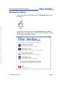
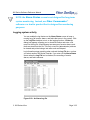
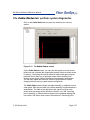
Fiber Defender™ 500 Series Software Suite User Manual Rev. E 8/2013 500 Series Software Reference Manual © Copyright 2013, Fiber SenSys® all rights reserved. No part of this publication may be reproduced or transmitted in any form or by any means, electronic or mechanical, including photocopy, recording, or any information storage and retrieval system, without permission in writing from Fiber SenSys®, Inc., 2925 NW Aloclek Drive, Suite 120, Hillsboro, Oregon 97124, USA. This manual is provided by Fiber SenSys Inc. While reasonable efforts have been taken in the preparation of this material to ensure its accuracy, Fiber SenSys Inc. makes no express or implied warranties of any kind with regard to the documentation provided herein. Fiber SenSys Inc. reserves the right to revise this publication and to make changes from time to time in the content hereof without obligation of Fiber SenSys Inc. to notify any person or organization of such revision or changes. Fiber Defender™ is a trademark of Fiber SenSys Inc. Fiber SenSys® is a registered trademark of Fiber SenSys Inc. Windows® is a registered trademark of Microsoft Corporation. Fiber SenSys Inc. 2925 NW Aloclek Dr. Suite 120 Hillsboro, OR 97124 USA Tel: 1-503-692-4430 Fax: 1-503-692-4410 [email protected] www.fibersensys.com Page ii Application Note 500 Series Software Reference Manual Table of Contents Contents Fiber Defender™....................................................................................... i 500 Series ................................................................................................. i Software Suite ........................................................................................... i User Manual .............................................................................................. i Table of Contents .................................................................................... iii 1. Getting Started ..................................................................................... 1 Product Description ...................................................................... 1 System Requirements .................................................................. 2 Installing the software ................................................................... 2 Running the software .................................................................... 3 2. 500 Series Config ................................................................................. 4 Help for 500 Series Config ............................................................ 4 Configuring a new system............................................................. 5 Restoring the system configuration ............................................. 12 500 Series Config Diagnostics .................................................... 13 Setting the APU Time ................................................................. 17 Advanced Settings ...................................................................... 18 Intelligent Zone Assignment........................................................ 20 3. 500 Series View ................................................................................... 1 Start 500 Series View ................................................................... 1 Help for 500 Series View .............................................................. 2 The APU Parameters tab: define and calibrate hyperzones .... 3 Assign a device name ....................................................... 3 Hyperzones ....................................................................... 4 General APU parameters .................................................. 6 Page iii Event Processing ............................................................ 12 Saving and restoring calibration settings ......................... 18 System performance testing ............................................ 19 The Realtime tab: view and record live sensor data ................ 20 Realtime display modes ............................................... 21 Recording realtime data .................................................. 23 The Replay tab: view and analyze saved data .......................... 25 The Model tab: model calibration data ...................................... 29 Writing modeled parameters to the APU ......................... 32 Spectral modeling example ............................................. 32 The Alarm Status tab: view and log system activity................ 34 Logging system activity ................................................... 35 The Cable Status tab: perform system diagnostics................. 37 Storing sensor magnitude values .................................... 38 Loading sensor magnitude values ................................... 38 Capturing Cable Status screen data ........................... 39 Updating sensor magnitude values in the APU ............... 40 The Filter tab: adjusting the digital filter .................................... 41 4. 500 Series Log ................................................................................... 44 The View tab: viewing alarm log data ....................................... 44 View filters..................................................................... 45 Zoom............................................................................... 46 The Stat tab: view alarm counts by zone................................... 46 Page iv 1. Getting Started The Fiber SenSys® 500 Series Software Suite consists of several Windows-based configuration and calibration software modules for the Fiber Defender™ 500 series of alarm processing units (APU). The software allows you to communicate with an APU from a PC via an intuitive graphical user interface (GUI). A properly configured and calibrated 500 series APU not only detects intrusion threats accurately, but also recognizes and ignores nuisances. Using the software suite, you can optimize your system to achieve a high probability of detection while effectively screening out nuisance alarms. Configuration and calibration is performed at installation; then again at any time a system component is repaired, replaced, or otherwise serviced. 500 Series Port Assignment Wizard assists with the installation of a new system. This software is easier to use and replaces the functionality of 500 Series Config. This software is described in AN-SM-023, the Port Assignment Wizard application note and is not covered by this manual. 500 Series Config allows you to specify configuration characteristics of the system’s cable assembly necessary for proper APU function. 500 Series View allows you to calibrate your system, monitor system performance, and record and analyze sensor data. 500 Series Log is a utility used to view and track system activity. Product Description Use 500 Series Suite to perform functions such as: Configure the intrusion-detection system Create hyperzones Calibrate the system View real-time signals from the cable assembly Record and save signals from the sensor cables Review and analyze recorded sensor-cable signal files Predict optimal system calibration settings through signal modeling 2. 500 Series Config Page 2-1 500 Series Software Reference Manual Perform baseline system diagnostics System Requirements The software suite can be installed on any PC meeting these minimum requirements: Operating system Windows XP with Service Pack 3 (SP3), Windows Vista with SP2, Windows 7 with SP1, or Windows 8 Supporting software Microsoft.NET framework 4.0 (included with software suite installer) Processor 2.8GHz Intel Pentium 4 or 2.0 GHz Dual Core or faster Other Recommended configuration for the operating system Installing the software To install the software suite: 1. Turn on the PC. 2. Insert the installation CD into the PC’s disk drive. 3. Follow the setup wizard prompts. If the setup wizard does not appear, it can be started manually by double-clicking on setup.exe from the CD. 4. By default, the setup wizard installs the software in the Program Files folder. You can specify a different location by clicking on the Browse… button on the setup wizard dialog box. 5. By default, the installer will place an icon on the PC desktop. Page 2-2 2.500 Series Config Application Note 500 Series Software Reference Manual Running the software To start the software suite, double click on the 500 Series Suite icon on the desktop. You can also start the suite by locating 500 Series Suite in the Fiber SenSys folder in the Start menu. The suite launcher will appear, allowing you to select the appropriate software. 2. 500 Series Config Page 2-3 500 Series Software Reference Manual 2. 500 Series Config Use the 500 Series Config software to configure your Fiber SenSys security system. This step is essential for proper APU functioning. Configuration involves programming critical cable-assembly information into the 500 series APU. Before starting system configuration, you must know the length of the lead-in cable and the overall length of the backbone cable, in meters. NOTE: A new system must be configured using 500 Series Config before calibration parameters can be set using 500 Series View. Help for 500 Series Config When using 500 Series Config, this manual is available from the pulldown menu at the top of the screen. To open this manual, select the User Manual option from the Help menu. Figure 2-1. 500 Series Config main Help menu Page 2-4 2.500 Series Config Application Note 500 Series Software Reference Manual NOTE: Tool tips appear when you move the cursor over a control on the screen. Configuring a new system NOTE: 500 Series Port Assignment Wizard assists with the installation of a new system. This software is easier to use and replaces the functionality of 500 Series Config, including Intelligent Zone Assignment. This software is described in ANSM-023, the Port Assignment Wizard application note, and is not covered by this manual. To configure your system, follow these steps: 1. To launch the software, use the 500 Series Suite launcher or select the Start button and navigate to “All Programs | Fiber SenSys | 500 Series Config”. 2. The main 500 Series Config screen displays behind the APU Connection dialog box. The PC scans its communication ports and detects the APU, then establishes communication with the APU. The 2. 500 Series Config Page 2-5 500 Series Software Reference Manual APU Connection dialog box disappears. Figure 2-3. 500 Series Config searches for the APU Page 2-6 2.500 Series Config Application Note 500 Series Software Reference Manual 3. The main 500 Series Config screen displays: Figure 2-4. 500 Series Config main screen 4. Two cable configuration values appear in the upper left portion of the screen, Lead Length and Backbone Length. These fields show the values previously stored in the APU, if any. Figure 2-5. Editing APU settings field 5. Enter the approximate length of the insensitive lead-in cable in meters in the Lead Length box. Ensure that the value entered is greater than the actual lead-in cable length. 6. In the Backbone Length box, enter the approximate end-to-end length of the backbone cable plus 100 meters, not including the 2. 500 Series Config Page 2-7 500 Series Software Reference Manual insensitive lead-in cable. Make sure the value entered is at least 100 meters longer than the actual length of the backbone cable. 7. Click on the Write button to save the lead length and backbone length values to the APU. CAUTION: Any time you enter new data on the 500 Series Config screen, the Write button starts flashing yellow, indicating there is new data to download to the APU. Be sure to click on the Write button to save the new data. If you exit this screen without clicking on the Write button, the data is discarded and not saved to the APU. 8. Click on the Configure button. The system begins a configuration scan of the connected cable assembly. The X axis represents distance in meters, and the Y axis represents optical power expressed as a percentage. CAUTION: The intrusion-detection system is temporarily disabled during the scanning process. Each peak in the waveform represents the optical signal reflected from a sensor cable. There is one reflection for each sensor cable in the cable assembly, plus the reference reflection from the splitter box. Page 2-8 2.500 Series Config Application Note 500 Series Software Reference Manual Figure 2-6. Completed configuration scan 9. During a configuration scan, the 500 series APU calculates the location of the center of each reflection that appears on the waveform. This is the location of each sensor cable along the backbone, in meters. These locations are listed in the Zone Reflection Locations table on the 500 Series Config screen. . The first column in the Zone Reflection Locations table identifies the reflection number. The second column identifies the location of the reflection, in meters. The third column identifies the zone number associated with that reflection. The first row in the table represents a reference reflection within the APU and the last row in the table represents the noise floor. 2. 500 Series Config Page 2-9 500 Series Software Reference Manual Depending on the site configuration, the order of the reflections might not match your desired zone order. If this is the case at your site, consider using the Intelligent Zone Assignment feature, described in the Advanced Menu section. When the configuration scan is complete, make sure all the locations listed are correctly centered on the reflections. Click on each location listed in the Locations box. On the waveform, the white distance cursor moves to the reflection at that location. Verify that the distance cursor looks centered on the reflection at the selected location. NOTE: You can zoom in on any portion of the scan, using the cursor to outline the area to view. Click Zoom Out to increase the area in view, and Normal to return to the original view. Figure 2-7. Zooming in on the waveform If the location of a reflection is not exactly centered, use the Remove and Insert buttons to relocate the center. With the location selected in the Page 2-10 2.500 Series Config Application Note 500 Series Software Reference Manual list, click Remove. Then drag the distance cursor to the center of the reflection, and click Insert to establish the new center point. 11. After checking that each location listed corresponds to the center of each reflection on the waveform, save the data by clicking on the Write button to complete system configuration. 12. To save the configuration data to a file on the PC, select the File pulldown menu from the menu bar at the top of the screen, and select the Save APU settings option. A Save Config File As dialog box appears, requesting a file name and location for the file. The file extension .cfg is provided automatically. Specify a filename and location for the configuration file. The 500 Series Config software saves the file with the extension .cfg. Figure 2-8. Save APU settings 2. 500 Series Config Page 2-11 500 Series Software Reference Manual 13. To save the waveform data to a file on the PC, select the Graph pulldown menu from the menu bar, and select Save to File. A Save Graph Data File As dialog box appears, requesting a file name and location for the file. The file extension .dat is provided automatically. Specify a filename and location for the waveform data. 500 Series Config saves the file with the extension .dat. Figure 2-9. Save waveform data to a file 14. Exit the 500 Series Config program. You can either select Exit from the File menu, or click on the Windows close button (X) in the upper right-hand corner of the 500 Series Config window. 15. Configure the intrusion-detection system using 500 Series View according to the instructions given in the next chapter of this manual. Restoring the system configuration System configuration can be restored from a saved configuration (.cfg) file. Restore system configuration after the APU has been replaced due to servicing. NOTE: Do not restore the system configuration if sensor cables or the backbone cable has been serviced. In that case, the system must be reconfigured using the same procedure for configuring a new system. To restore system configuration, follow these steps: Page 2-12 2.500 Series Config Application Note 500 Series Software Reference Manual 1. Select the drop-down File menu from the 500 Series Config menu bar, and click on the Load APU settings option. An Open Config File dialog box appears that allows you to browse the PC’s hard drive. Select the .cfg file that contains the required configuration data. 2. When you open the .cfg file, the 500 Series Config screen is populated with the data from the file. Verify that the configuration data is correct. 3. Click on the Write button to write the data to the APU. 4. Reconfigure the system according to the instructions given in the following chapter on the 500 Series View program. Set configuration parameters on the APU Parameters screen in 500 Series View. 5. After setting configuration parameters, conduct the system performance tests given in the APU’s manual. 500 Series Config Diagnostics You can compare system performance at different times, or compare current system performance against that of an earlier configuration. This is done by acquiring spectral data, saving the resulting waveform into a file on the PC, then comparing the saved data to a current waveform. To compare data, use the Capture function, as follows: 1. First, load a saved waveform. Select the drop-down Graph menu from the 500 Series Config menu bar, and click on the Load from File option. 2. 500 Series Config Page 2-13 500 Series Software Reference Manual Figure 2-10. Graph menu Load from File option A Load Graph Data File dialog box appears that allows you to browse the PC’s hard drive. 2. Select the .dat file that contains the corresponding waveform data. The waveform is drawn in the graph area of the display. Figure 2-11. Loading a waveform from a .dat file Page 2-14 2.500 Series Config Application Note 500 Series Software Reference Manual 2. With the comparison waveform loaded, select the drop-down Graph menu again, and click on the Capture option. The current waveform on the 500 Series Config screen changes from red to blue, indicating the waveform has been “captured” and will be retained on the screen when a new waveform is either acquired or loaded from another file. Figure 2-12. The Capture function on the Graph menu 2. 500 Series Config Page 2-15 500 Series Software Reference Manual 3. With the captured waveform on the screen, click on the Scan button to acquire new spectral data for the cable assembly. When the new data is acquired, both the captured waveform and the live waveform are shown on the 500 Series Config screen together. You can then use the zoom function to compare the two traces. Figure 2-13. Comparing captured and live waveform traces NOTE: This procedure starts with loading a .dat file and compares the waveform from the file to a new scan, but you can also start with a current scan, capture it, and load a second waveform from a file for comparison. Page 2-16 2.500 Series Config Application Note 500 Series Software Reference Manual Setting the APU Time The 500 Series APU contains an internal real-time clock. This clock is set at manufacturing time but can also be set by the customer by accessing the APU → Set APU Time menu item, which will bring up the following form. Figure 2-14. Setting the APU Time This form reports the current APU date and time as well as the current date and time on your PC. The format for these value should match your locale's standard format: month/day/year in the United States, day/month/year in the United Kingdom, and so forth. Pressing OK will close the form after setting the APU's date and time. Pressing Cancel will close the form without changing the APU. 2. 500 Series Config Page 2-17 500 Series Software Reference Manual Advanced Settings 500 Series Config includes some advanced capabilities that are not designed for regular use. These capabilities can be accessed via the APU → Advanced menu item, which will bring up a form containing advanced settings. CAUTION: Some of the settings accessible from the Advanced Settings form are critical. Changing these values could result in a non-functioning system. Fiber SenSys does not recommend changing the values on this form unless you have been trained in their use. Figure 2-15. Confirmation dialog for Advanced Settings form The Laser Current field reports the automatically adjusted current value at the time that the form was created. It is used for customer support diagnostics. The Default laser current value indicates the percentage of current capacity that the APU should use as its starting current. The Fault Threshold indicates the percentage of average signal value below which the zone should be considered in fault. The Write button must be pressed to send the updated field values to the APU. Page 2-18 2.500 Series Config Application Note 500 Series Software Reference Manual Figure 2-16. Advanced Settings form The Allow Intelligent Zone Assignment checkbox allows the Intelligent Zone Assignment feature to be accessed from the Zone Reflection Locations table. This feature allows flexibility in assigning zone numbers to zones. The checkbox does not change any assignments that already exist in the APU and the Write button does not need to be pressed. The checkbox must be checked each time you re-start 500 Series Config. Please refer to the section on Intelligent Zone Assignment for more information about this feature. 2. 500 Series Config Page 2-19 500 Series Software Reference Manual Intelligent Zone Assignment The Intelligent Zone Assignment feature allows flexibility in assigning zone numbers to zones. The assigned zone numbers are used for the LEDs, relays, FD525 View, and XML (Fiber Commander). 500 Series Config prevents the user from duplicating or skipping numbers, so only the sequence of the numbers is changed. The primary advantage of this feature is that customers do not need to insert fiber delay coils to achieve their desired zone numbering sequence. For example, if you have a long zone followed by a short zone, you can now call these zones “1” and “2” through software. Once enabled, the user can change the numbers assigned to zones by clicking on the associated row in the Zone Reflection Locations table, then double-clicking on the Zone # cell for that row. A dropdown will appear, allowing the user to assign a new zone number for that reflection. Figure 2-17. Using the Intelligent Zone Assignment feature Click elsewhere to commit the assignment. Once the assignment is committed, the Write button will flash to remind the user that the Zone Reflection Locations table no longer matches the table in the APU. The "-" item is not a valid zone number. 500 Series Config will not allow the user to assign this value. The Reset Zone Order button will restore the zone numbers such that each matches the reflection number. If you inadvertently press this Page 2-20 2.500 Series Config 500 Series Software Reference Manual Application Note button, you can use the Read button to read the current settings from the APU, including the Zone Reflection Locations table. 2. 500 Series Config Page 2-21 500 Series Software Reference Manual 500 Series Config prevents the user from duplicating or skipping numbers, so before the table can be written to the APU, the user must first assign a unique number to each zone. 500 Series Config highlights duplicate zone numbers to remind the user to assign unique numbers. Figure 2-18. Highlighted duplicate zone numbers. If the user attempts to write the table before assigning unique numbers, an error dialog appears indicating that the settings cannot be written. Figure 2-19. The duplicate zone numbers error dialog. Once each zone has been assigned a unique number and the Write button is pressed, the Zone Reflection Locations table will be written to the APU. The assigned zone numbers will then be used for the LEDs, relays, 500 Series View, and XML (Fiber Commander). Page 2-22 2.500 Series Config FD525 Software Reference Manual 3. 500 Series View Use 500 Series View to set calibration parameters for your security system. Effective calibration of the system minimizes nuisance alarms and optimizes its probability of detection. Configure the system when it is first installed, and also after any servicing of the cable assembly or APU. Using 500 Series View, you can also record sensor data files, analyze the frequency content of saved data, perform sensor data modeling, and perform routine cable-assembly diagnostics. Start 500 Series View 1. Connect the PC running 500 Series View to the USB port of the 500 series APU. Turn power on to the APU. 2. To launch the software, use the 500 Series Suite launcher or select the Start button and navigate to “All Programs | Fiber SenSys | 500 Series View”. 3. 500 Series View starts up, with the APU Parameters tab selected. The screen displays calibration information read from the APU. 3. 500 Series View Page 3-1 500 Series Software Reference Manual Help for 500 Series View Online help for 500 Series View is available from the pull-down menu at the top of the screen. To view the main help screen, select the Help option from the Help menu. Figure 3-1. 500 Series View main Help menu To view help in context, right click on any field on the screen to display a pop-up Help option, and left click on the pop-up. This displays the specific help text for that field. Figure 3-2. Context help option for APU Read/Write controls Page 3-2 3. 500 Series View 500 Series Software Reference Manual The APU Parameters tab: define and calibrate hyperzones Use the APU Parameters screen to assign the physical zones of your system to hyperzones, and to specify calibration parameters for each hyperzone. Figure 3-3. The 500 Series View APU Parameters screen Assign a device name For a new installation, assign a unique device name to the APU. This will be the name used to address the device in all XML messages if your APU is installed in an existing local-area network. Click on the Device Name field on the APU Parameters screen and enter the name. Click on the Write button to write the name to the APU. 3. 500 Series View Page 3-3 500 Series Software Reference Manual Hyperzones Next, organize your secure perimeter into hyperzones. A hyperzone is a virtual zone in your perimeter security system that consists of one or more actual physical zones. For example, each physical zone can be a separate hyperzone; or alternatively, all the zones of your perimeter can be in one hyperzone. Group physical zones into hyperzones according to how you plan to assign calibration parameters. This feature enables you to apply the same calibration settings to separate zones that have similar physical traits. Hyperzones might indicate places where the environment changes, for example, from open space to a treed area, or areas that might be affected by vibrations from traffic or railway. After a 500 Series Config APU configuration, all zones are grouped into one hyperzone, containing all the physical zones in the system. To create a new hyperzone and add a zone to it, activate the APU Parameters tab and right click on the zone to be moved. Select the popup Add to new Hyperzone when it appears. A new hyperzone is created containing the selected zone. Figure 3-4. Creating a new hyperzone You can right-click over any listed zone to continue creating new hyperzones. After creating new hyperzones, you can also move individual zones by dragging them in the hyperzone tree from one hyperzone to another. Page 3-4 3. 500 Series View 500 Series Software Reference Manual Rename zones To rename a zone, click on the zone to select it, wait a second and then click on it a second time. A text cursor appears in the name field, and you can type in a new name. After hyperzones are defined and named, calibrate the system by assigning calibration parameters to each hyperzone. All calibration parameters are assigned on the APU Parameters screen. As discussed earlier, each hyperzone is calibrated independently. When a new hyperzone is created, 500 Series View assigns default settings to each calibration parameter. You can change these settings for each hyperzone. If you remove a zone from one hyperzone and add it to another, the zone is automatically assigned the calibration parameters of the new hyperzone. To adjust the calibration parameters for a hyperzone, select the hyperzone either by double clicking on it, or by right clicking on it and choosing Select from the pop-up menu. The selected hyperzone is highlighted. With the hyperzone selected, change the value of any calibration parameter, either using the arrow keys, or by typing a new value into the associated box and pressing Enter. If you enter a number outside the allowed range, 500 Series View automatically changes it to the closest allowed value. After setting calibration parameters, make sure to click on the Write button to write the parameters to the APU. 3. 500 Series View Page 3-5 500 Series Software Reference Manual CAUTION: Do not select another hyperzone for calibration before clicking on the Write button. If you change hyperzones before saving the calibration parameters, all new parameter values are discarded. General APU parameters Some general APU settings are found in the lower right-hand corner of the 500 Series View APU Parameters screen. The APU contains two processors that analyze the incoming cable-assembly signal to detect events and alarm conditions that occur along your secured perimeter. General APU parameters are applied by hyperzone to both processors. For each parameter, the range of allowed values is shown, as well as the default value. Figure 3-5. General APU parameters Page 3-6 3. 500 Series View 500 Series Software Reference Manual Sensitivity Begin system calibration with the sensitivity setting for each hyperzone. The sensitivity value specifies how much the incoming signal from the cable assembly is amplified. A higher sensitivity setting, for example, is more likely to detect an intrusion, but also more likely to trigger a nuisance alarm. Try to optimize the sensitivity setting to a level where intrusions are detected without increasing the likelihood of nuisance alarms, by adjustment and subsequent system testing. Typically, sensitivity is set only when the system is first installed. The following figure shows the effects of different sensitivity settings on the incoming signal. Figure 3-6. Sensitivity setting adjustment principle To adjust the sensitivity, follow these steps: 1. Start with the default sensitivity setting. At a zone in the first hyperzone, simulate the desired level of intrusion the system should recognize (climbing or cutting the fence, or stepping into the security zone, for example), and verify that an alarm condition occurs. 3. 500 Series View Page 3-7 500 Series Software Reference Manual Simulate chain-link fence cutting by attaching a spare section of chain link to the fence and securing it using cable ties. Cut the links of the spare section and check the system response. 2. Adjust the sensitivity if necessary, raising it only to the minimum level necessary to detect the simulated intruder. Click on the Write button to activate the new sensitivity setting for the current hyperzone, and to write the new setting to the APU. 3. Repeat the test in every hyperzone of the perimeter as well as in the most likely locations for an intrusion. Adjust the sensitivity setting in the corresponding hyperzone as necessary. Prefilter A Prefilter % parameter setting controls a high-pass filter used when acquiring waveform data. This value is a percentage, indicating the filtering that is applied: 0 for none, and 100 for the maximum filtering. Note that applying 100% filtering cuts off most of the signals below the 50-Hz level. The primary function of this setting is to filter out extraneous signals caused by nuisance sources that typically exist at low frequencies. Click on the Write button to activate changes to the setting for the currently selected hyperzone and save the new value to the APU. Use the prefilter in combination with sensitivity to manipulate the raw sensor signal before the alarm processors analyze it. Typically the signal generated in fence applications has a practically equal amount of lowfrequency content generated during windy conditions as with actual intrusions. By increasing both the prefilter percentage and sensitivity, a more “tunable” spectrum can be generated. Page 3-8 3. 500 Series View 500 Series Software Reference Manual Gain Like the sensitivity setting, the gain setting is applied simultaneously to all zones within a hyperzone. The gain setting adjusts how the APU interprets the incoming signal. The APU calculates the area under the signal between the low- and high-frequency bounds. The gain is the threshold for this calculation, below which all activity is ignored. Raising the gain value lowers the threshold, allowing more signals to qualify for processing, and lowering the gain value raises the threshold, screening out more signals. A higher gain value increases the likelihood of detecting an intruder, but also increases the likelihood of nuisance alarms. As with the sensitivity setting, set the gain value to the level necessary to detect an intrusion while also minimizing the incidence of nuisance alarms. Figure 3-7. Gain adjustment principle 3. 500 Series View Page 3-9 500 Series Software Reference Manual To adjust the gain, follow these steps: 1. Start with the default gain setting. At a zone in the first hyperzone, simulate the desired level of intrusion the system should recognize (climbing or cutting the fence, or stepping into the security zone, for example), and verify that the APU indicates an alarm condition. Simulate chain-link fence cutting by attaching a spare section of chain link to the fence and securing it using cable ties. Cut the links of the spare section and check the system response. 2. Adjust the gain if necessary, setting it only to the level necessary for the APU to detect the simulated intruder. 3. Click on the Write button to activate the new setting for the selected hyperzone, and save it to the APU. 4. Repeat the test in every hyperzone of the perimeter as well as in the most likely locations for an intrusion. Adjust the gain in the corresponding hyperzone as necessary. Page 3-10 3. 500 Series View 500 Series Software Reference Manual Wind processing The effects of wind must be considered and compensated for in all fencemounted applications. These effects can be dampened in each hyperzone independently. When wind processing is turned on, as the wind load picks up, the APU automatically scales back (or "dampens") the gain in accordance with the wind-rejection factor. A higher wind-rejection factor means more dampening, requiring a signal higher in magnitude to create an alarm condition. With no wind load, the gain returns to its normal setting. Figure 3-8. Wind reduction principle Use the Wind Reject checkbox to enable wind-rejection processing, then adjust the value if necessary. Click on the Write button to activate the new settings for the selected hyperzone, and to save them to the APU. Adjust wind-processing parameters, if necessary, only after adjusting gain for each hyperzone. For buried sensor applications, leave the Wind Reject box unchecked. 3. 500 Series View Page 3-11 500 Series Software Reference Manual Event Processing Event-processing parameters define: 1) how the signals from the sensor cables are interpreted as events, and 2) how events define alarm conditions. Event-processing parameters are applied separately to the two APU processors, by hyperzone. Adjust event-processing parameters, if necessary, only after adjusting the gain for each hyperzone. In the 500 series APUs, two separate processors evaluate the incoming signal. These processors, labeled Proc1 and Proc2 on the 500 Series View APU Parameters screen, are programmed individually to alarm for different conditions. This allows you to program Processor 1 and Processor 2 to evaluate the incoming signal for different intrusion conditions. When a disturbance is detected in the returning optical signal and conditions meet the criteria in either Processor 1 or Processor 2, an alarm condition results. Processor 1 default settings are optimized to detect fence climbing and Processor 2 settings are optimized to detect fabric cutting. Use the Enable check box to enable or disable the processor. For each parameter, the range of allowed values is shown, as well as the default value. Figure 3-9. Event-processing parameters Page 3-12 3. 500 Series View 500 Series Software Reference Manual Defining events The first five parameters for each processor define the characteristics of events: Signal level – the signal level of a nuisance is generally lower than that of an intrusion attempt. A signal from the sensor cable must be higher than this level to be counted as an event. The gain setting should always be greater than the Signal level. High frequency and low frequency – an intrusion attempt or a nuisance generates a unique frequency signature as the sensor cable is disturbed. For example, an intruder climbing a fence generates noise at the low end of the frequency spectrum, while a cut through a tight fence produces high-frequency oscillations. Selecting the right frequency range helps filter out frequencies caused by nonthreatening events. Figure 3-10. Frequency limit principle Signal duration – the time interval necessary for a signal to qualify as an event, in tenths of a second. This parameter works in tandem with the signal-level setting. The duration of a signal can help distinguish an intrusion attempt from a nuisance. Some low-magnitude nuisances can cause more lengthy disturbances than an intruder, while highmagnitude nuisances, such as the popping of a metal fence in 3. 500 Series View Page 3-13 500 Series Software Reference Manual changing temperatures, are very short in duration. Coupling signal duration with the signal level can help screen out a number of nuisances this way. In the example shown below, a signal must be both higher than the 10 dB threshold and longer than 3/10 second to qualify as an event. Figure 3-11. Signal duration coupled with signal level Tolerance – this parameter specifies a tolerance for the signal-level setting. If the signal falls within this tolerance below the signal-level setting, it is considered an event if it lasts for a period of time that is automatically set by the processor. The higher the tolerance value is, the longer the duration. If the signal is outside the tolerance setting, it cannot generate an event regardless of how long it lasts. Defining how events qualify as alarms The following three parameters define the conditions under which events qualify for an alarm condition. Page 3-14 Event count – one of the best ways to differentiate an intruder from a nuisance is by the number of times an event occurs within a given time period. Generally, a nuisance such as an animal or tree branch doesn’t cause the consistency in events that an intruder does. The event-count parameter specifies the number of events that must be 3. 500 Series View 500 Series Software Reference Manual received to cause an alarm condition, and is used with the eventwindow parameter. Event window – a window of time following an initial event, during which at least one subsequent event must occur and be complete to qualify for an alarm condition. This parameter is entered in tenths of a second. An event count of 1 means that any event will generate an alarm. In this case the event window is ignored. For example, if the event window setting is 50 (5 seconds) and the event count is 3, at least three events must occur no more than 5 seconds apart (a total time of 15 seconds) for an alarm to occur. If an event window expires before another event occurs, the event count resets, as shown in the illustration below: Figure 3-12. Event windows 3. 500 Series View Page 3-15 500 Series Software Reference Manual NOTE: Since the event must be completed within the event window to be counted towards an alarm condition, the event window must be at least as long as the event duration. NOTE: If the event-mask time is not zero, then a delay as long as the event mask time occurs before the event window time begins. If, however, the second event occurs before the first event window expires, the event count increments to 2. The third event falls within the event window of the second event, so the event count increases to 3 and creates an alarm condition, as shown below: Page 3-16 3. 500 Series View 500 Series Software Reference Manual Figure 3-13. Creating an alarm condition Event mask – the mask time is the period of time immediately following an event during which subsequent events are masked, or not counted. This period accounts for oscillations made after an initial strike against the fence by a bird or some other non-threatening nuisance. Oscillations from nuisances usually die down within 0.5 second. In the example shown below, the second event does not count because it occurs within the event mask of the first event. The second event does not increment the event count, so an alarm condition is not generated until the fourth event increments the count to 3. 3. 500 Series View Page 3-17 500 Series Software Reference Manual Figure 3-14. Counting valid events NOTE: Accurate setting of event parameters is usually determined through experimentation and testing of the system following installation. NOTE: After changing any of the Processor 1 or Processor 2 parameter settings, you must click on the Write button to activate the new settings for the selected hyperzone, and write them to the APU. Saving and restoring calibration settings You can save the calibration settings for all hyperzones in the system into one file. This allows you to restore all system settings to the APU if necessary. To save and restore calibration settings, use the buttons in the File menu while you are in the APU Parameters screen. Page 3-18 3. 500 Series View 500 Series Software Reference Manual Figure 3-16. File operation buttons To save calibration settings for all hyperzones, select the “Save settings” button. A Save As dialog box displays, requesting a file name and location for the file. The file extension .prm is provided automatically. Enter the file information on the Save As dialog box and click OK. 500 Series View reads all parameters from the APU for each hyperzone and stores them in the designated file. The values read from the APU for the currently selected hyperzone are also displayed on the APU Parameters screen. To restore all APU settings, select the “Restore settings” button. An Open dialog box displays. Select the correct .prm file and click OK. 500 Series View writes all parameter settings from the file to all hyperzones on the APU. This may take several seconds, depending on how many hyperzones are in the system. The values written from the file to the APU for the currently selected hyperzone are also displayed on the APU Parameters screen. System performance testing After configuration and calibration, system performance must be tested to ensure that the security system is optimized; that is, the highest probability of detection and the lowest incidence of nuisance alarms are achieved. Instructions on conducting system performance testing on new and recently maintained systems are found in the APU’s manual. 3. 500 Series View Page 3-19 500 Series Software Reference Manual The Realtime tab: view and record live sensor data In addition to system calibration, 500 Series View also gives you the ability to view and record live signals from any zone in the cable assembly. To use this function, click on 500 Series View’s Realtime tab. You can display real-time data for any zone listed in the hyperzone tree by double clicking on the selected zone. 500 Series View pauses momentarily while establishing contact with the new zone. A progress bar in the lower right corner of the screen shows the display being updated in real time. Figure 3-17. The 500 Series View Realtime screen A status legend on the right-hand side of the screen shows any alarms or events associated with Processor 1 and 2. Alarm indicators are shown in red and event indicators are yellow. Events and alarms are also shown as flashes across the Realtime screen. Page 3-20 3. 500 Series View 500 Series Software Reference Manual Figure 3-18. Realtime status display Table 3-1. Realtime status display indicators Indicator Meaning P1 Alarm Alarm condition in Processor 1 P1 Event Event condition in Processor 1 P2 Alarm Alarm condition in Processor 2 P2 Event Event condition in Processor 2 Fault Fault condition in the cable assembly Relay Alarm relay has been activated Tamper Tamper switch has been activated Realtime display modes On the Realtime screen, you can choose from two modes for viewing live sensor cable signals, Spectral or Time. Choose between these modes by clicking on the appropriate radio button. Data is displayed for the currently selected zone. In either display mode, the data is updated about ten times per second. 3. 500 Series View Page 3-21 500 Series Software Reference Manual Spectral display mode – Provides a display of amplitude vs. frequency. The relative acoustic power of the signal (a unitless measure) is shown along the Y axis, and the X axis shows the associated frequency content (Hz). Figure 3-19. Realtime spectral display mode Time display mode – Provides a plot of signal amplitude along the Yaxis vs. time measured in points along the X-axis. Figure 3-20. Realtime time display mode Page 3-22 3. 500 Series View 500 Series Software Reference Manual Recording realtime data You can save the realtime data to a file for later analysis. The save function can be triggered either manually or automatically, such as when an alarm or event is detected. When either a manual or an automatic trigger is received, 500 Series View records five seconds of data. The five seconds of data following the trigger is coupled to five seconds of data that immediately preceded the trigger, for a total 10-second “snapshot” of sensor cable data, as shown below. The trigger occurs at 0 seconds. Figure 3-21. Recording of realtime data All hyperzone information and calibration settings associated with the selected zone are saved with the file.The controls that allow you to record realtime sensor cable data are in the upper right area of the Realtime screen. Figure 3-22. Realtime screen recording controls 3. 500 Series View Page 3-23 500 Series Software Reference Manual Sensor cable data is saved in files using the following file name format: prefix.xx.yyy.fsi The prefix is user specified, and entered in the Prefix field on the Realtime screen. This allows you to create a series of files identified by a common prefix, for example, by location, such as “NE Corner A1.” The xx is the currently selected zone number, supplied automatically when the file is saved. The yyy is an automatically incrementing sequence number that starts at 0 and increments each time a file is saved with the same prefix. You can change the sequence number manually by clicking on the up and down arrows in the Sequence box. By default, sensor cable data files are saved to the My Documents folder. You can specify a different location for saved files by clicking on the Path field and selecting from the Browse for Folder dialog box that appears. Recording data manually Make a recording of realtime sensor cable data for the currently selected zone at any time as follows: 1. In the Record File Prefix field, specify a file name. If necessary, enter a new destination directory for the file in the Path field. 2. Click on the Record button. 3. The message Manual Record… appears in the message bar at the bottom of the screen while data is recorded. 4. After five seconds, the save is complete. 500 Series View displays the path and filename of the saved file in the message bar. Recording data automatically You can save sensor cable data automatically by specifying the automatic trigger. There are four automatic trigger options: when an event is detected by Processor 1, when an event is detected by Processor 2, when an alarm condition occurs in Processor 1, and when an alarm condition occurs in Processor 2. Each of these triggers is enabled by Page 3-24 3. 500 Series View 500 Series Software Reference Manual clicking in the appropriate checkbox in the Event Record controls of the Realtime screen. To record sensor cable data automatically, follow these steps: 1. Under Record File, specify a filename prefix and destination directory for the data file(s). 2. Check one or more of the trigger checkboxes under Event Record to enable the selected trigger(s). 3. When any of the selected triggers occurs, 500 Series View begins recording five seconds of sensor cable data. The message Event save in progress… appears on the message bar at the bottom of the screen while the recording is in progress. 4. After five seconds, the save is complete. 500 Series View displays the path and filename of the saved file in the message bar. The Replay tab: view and analyze saved data Import spectral data and analyze the frequency content on the 500 Series View Replay screen. The Replay screen displays signal data that was recorded on the Realtime screen. 3. 500 Series View Page 3-25 500 Series Software Reference Manual Figure 3-23. The Replay screen To replay realtime spectral data: 1. Click on the Open button. An Open dialog box displays, allowing you to browse the files on the PC. 2. Select a data file (.fsi extension). 500 Series View imports the file and displays its data in both the Spectrum and Acoustic Power windows. All hyperzone and calibration parameter settings associated with the zone are also imported. The file name and data/time stamp of the file are displayed in the field next to the Open button. You can click on the APU Parameters tab to view the calibration parameter settings associated with the file. This data is displayed, but not written to the APU unless you click on the Write button on the APU Parameters screen. The buttons labeled Previous and Next allow you to scroll through all the files in a series; that is, files with the same filename prefix but with incrementing sequence numbers. The Replay screen provides two ways of viewing the spectral data: Page 3-26 3. 500 Series View 500 Series Software Reference Manual Spectrum window – Displays the signal amplitude as a function of signal frequency (Hz). Acoustic Power window – Displays the raw signal’s acoustic power as a function of time. Yellow and red markers above the waveform indicate event and alarm points. The 0.0 position on the X axis indicates the trigger point of the recording, while the negative numbers indicate the time in seconds leading up to the trigger. The two windows are interactive; that is the data appearing between the blue cursors in one window is a conversion of the data between the blue cursors in the other window. Initially the blue cursors are positioned at the left and right edges of each window. You can drag and reposition any of these cursors within its window. As you drag a cursor, narrowing the focus of data in that window, the other window is automatically updated. For example, the cursors in the Acoustic Power window are initially displayed at -5 and +5 seconds. Moving these cursors to the +1 and +2 second positions updates the Spectrum window to display the frequency content of the signal that occurs only between those points in time. Similarly, placing the markers between the 100 and 200 Hz positions in the Spectrum window updates the Acoustic Power window to display only the signal amplitude content present in that frequency range. Cursors 3. 500 Series View Page 3-27 500 Series Software Reference Manual Displayed frequency data changes as the range of acoustic power data changes Figure 3-24. Changing the range of displayed data on the Replay screen You can move both cursors as a pair by right clicking over either one and dragging. Double clicking on a window’s X axis at any time returns the cursors to their default positions. The Replay screen helps you identify signals from unknown sources and compensate for them. If a recurring alarm from an unknown cause is received, for example, you can save waveforms using the Realtime screen, then view the results on the Replay screen. The presence of specific frequencies or frequency harmonics may help you identify vibration from nearby heavy equipment or vehicle traffic. By contrast, sporadic, low-magnitude signals that spread across the frequency spectrum may indicate a stealthy, fence-climbing intrusion attempt. Page 3-28 3. 500 Series View 500 Series Software Reference Manual The Model tab: model calibration data The Model screen allows you to adjust theoretical calibration parameter values and preview the potential effects on APU performance using previously saved sensor cable spectral data. This way, you can see the calibration parameter’s effects without actually changing APU settings, called spectral data modeling. Spectral data modeling allows you to derive the optimum calibration settings for each hyperzone in your system, speeding up the system calibration process. Figure 3-25. The Model screen To open spectral data for viewing on the Model screen: 1. Choose whether to load calibration parameter data with spectral data. Click the Load File Parameters box to load the calibration parameters, or leave the box unchecked to load spectral data only from the file, without the calibration parameter settings. 2. Click on the Open button. An Open dialog box displays, allowing you to browse the files on the PC. 3. 500 Series View Page 3-29 500 Series Software Reference Manual 2. Select a data file (.fsi extension). 500 Series View imports the file and displays its data in the Acoustic Power window. The file name and data/time stamp of the file are displayed in the field next to the Open button. If you had the Load Calibration Parameters box checked, you can click on the APU Parameters tab to view the calibration parameter settings associated with the file. This data is displayed, but not written to the APU unless you click on the Write button on the APU Parameters screen. The buttons labeled Previous and Next allow you to scroll through all the files in a series; that is, files with the same filename prefix but with incrementing sequence numbers. The spectral data displays relative acoustic power as a function of time. The Model screen shows two waveforms: a blue one indicating the modeled data, and a red one showing the actual acquired signal. Although there is initially some variation between the two waveforms, the modeled data and the acquired data will overlap until you make changes to the calibration parameter settings. Figure 3-26. Spectral data display on the Model screen Page 3-30 3. 500 Series View 500 Series Software Reference Manual The horizontal white line shows the event threshold. Yellow markers indicate events, where either of the waveforms crossed the event threshold. Red markers indicate alarm conditions. These markers show you when the signal generates event and alarm conditions at the current calibration parameter settings. The top row of markers corresponds with the acquired signal, and the bottom row of markers corresponds with the modeled signal. If nuisance activity is present, you can determine from the Model screen the calibration settings at which the activity causes events and alarms. You can then adjust the settings until these peaks drop below the event threshold. Notice how an alarm and an event marker have dropped off the modeled trace on the lower screen, after the tolerance parameter was adjusted. Figure 3-27. Modeling calibration parameters Notice that Processor 2 parameters are available on a tab behind Processor 1. Click on the Proc 2 tab to bring it to the front to adjust settings. 3. 500 Series View Page 3-31 500 Series Software Reference Manual Writing modeled parameters to the APU Any parameter setting changes made in the modeling process are also displayed on the APU Parameters screen. You can use the modeling process to derive optimal calibration parameter settings, then click on the APU Parameters tab to display the APU Parameters screen and view the new settings. To write the settings to the APU, click on the Write button. The new settings are saved to the APU, and applied to all zones in the selected hyperzone. You can then click on the Save button to save all parameter settings for all hyperzones in the system, including the updated hyperzone in a .prm file on the PC for future use. NOTE: If you decide not to save the modeled parameters, simply click on the Read button to discard the modeled parameter settings without writing them to the APU. Clicking on the Read button uploads parameter settings for the currently selected hyperzone and displays them on the APU Parameters screen. Spectral modeling example As an example of spectral data modeling, consider a site where a 500 series system is installed on a chain link fence that is protecting a perimeter next to a set of train tracks. A passenger train goes by twice a day, setting off alarms in all zones that run parallel to the tracks. The system must be calibrated so the train does not cause alarm activity, but the system can detect climbing and cutting intrusion attempts. All zones running parallel to the train tracks are grouped into the same hyperzone (Hyperzone 3). A series of sensor data recordings have been made during train passings. For comparison purposes, separate recordings of simulated combing and cutting attempts in the affected zones have also been made. The Model function is used to improve calibration settings, as follows: Page 3-32 3. 500 Series View 500 Series Software Reference Manual 1. Open a sensor data file showing the nuisance. The data’s calibration values are shown in the Calibration Parameters fields, and its hyperzone configuration is shown in the hyperzone tree. 2. Adjust parameter settings until the model trace drops below the event threshold and no event markers are present. Adjust the gain setting first, setting it just low enough to eliminate events, but no lower. 3. On paper, record the adjusted parameter settings. 4. Open a data file that includes a simulated intrusion attempt in the same hyperzone. 5. Set the calibration parameters to the settings recorded in step 3. 6. Repeat steps 1 through 5 as necessary, until the model trace from the nuisance file indicates no alarms and the model trace from the intrusion attempt file indicates event detection and alarm activity. 7. Click on the APU Parameters tab to display the APU Parameters screen. Click on the Write button to write the optimized parameter settings to the APU for Hyperzone 3. 3. 500 Series View Page 3-33 500 Series Software Reference Manual NOTE: Zone sensitivity and wind compensation parameters cannot be modeled on the Model screen. The Alarm Status tab: view and log system activity A diagnostic alarm status display is available by clicking on the 500 Series View Alarm Status tab. On this screen, system alarm, event, and fault indicators are updated in real time. Each zone in the system has its own indicator. With no activity, the zone is not highlighted. Events highlight the zone in yellow, alarms in red, and faults in blue. Figure 3-28. The Alarm Status screen The Alarm Status screen is useful as a diagnostic tool for determining the performance of the system. For example, this screen gives immediate alarm and event feedback during system performance checks. You can also localize a fault in the cable assembly by tracing the fault indicators on the Alarm Status screen, isolating it to the backbone cable or an individual sensor cable – a fault in the backbone cable cases fault indicators to illuminate from multiple successive zones. Page 3-34 3. 500 Series View 500 Series Software Reference Manual NOTE: the Alarm Status screen is not designed for long-term system monitoring. Instead, use Fiber Commander™ software or a similar product that is designed for monitoring purposes. Logging system activity You can enable the log feature on the Alarm Status screen to keep a running log of all events, alarms, and faults that occur in the system. Click on the Log File checkbox to turn on the logging function. A Save As dialog box appears, allowing you to choose a location and enter a file name for the log file. All subsequent occurrences of events, alarms, and faults are stored into the file. The file is a text file (.txt extension) and can be viewed and printed using a text editor such as Notepad. Log information stops recording when uncheck the Log File box, or when you select another 500 Series View tab. If you return to the Alarm Status screen when the Log File box is checked, the recording of events, alarms, and faults resumes. Figure 3-29. An Alarm Log file 3. 500 Series View Page 3-35 500 Series Software Reference Manual The alarm log lists events by date and time. A four-digit decimal code describes the activity associated with each zone. The code indicates whether there as been an event, alarm, fault, or tamper, and whether the alarm relay has been activated. A value of 0 indicates no activity for that zone. To read the code, convert the decimal value to its binary equivalent. The active bits indicate the type of activity. For example, the alarm log reports a decimal value of 1041 in Zone 2 at 14:11:32 hours. Converting 1041 to its decimal value yields a figure of 010000010001. This number is divided into three four-bit bytes of data. Each bit is then identified with a type of activity according to the log report bit structure as shown below. A 1 indicates activity; a 0 indicates no activity. Figure 3-30. Log Report bit structure The decimal value 1041, therefore, indicates that event activity on Processor 1 created an alarm condition, causing the alarm relay to activate. Page 3-36 3. 500 Series View 500 Series Software Reference Manual The Cable Status tab: perform system diagnostics Click on the Cable Status tab to monitor the health of your security system. Figure 3-31. The Cable Status screen On the Cable Status screen, you can view the system’s current sensor reflections and compare their magnitudes against historical values saved in memory. Comparing the sensor-reflection magnitudes against saved historical values alerts you to potential trouble zones resulting from damage to the sensor cable or weakening laser/detector performance. You can also update the reflection values to compensate for optical changes without having to repeat system configuration. The Cable Status screen shows the cable assembly in graphical form as a bar graph. Each sensor cable in the cable assembly is represented as a separate bar. The table to the right shows the signal level from each sensor as a percentage of the reference reflection (or in dB, if the Log box is checked). In order for data to appear on the graphical display and in the table, 500 Series View must be connected to a functioning APU. 3. 500 Series View Page 3-37 500 Series Software Reference Manual The first bar shows the height of the reference reflection, which is indicated by a horizontal line across the screen. A second horizontal line towards the bottom of the screen shows the noise floor. Small fluctuations in the magnitude of each reflection are normal, resulting from minor disturbances of the sensor cable. Minor variations in the system optics can also cause small changes in the reflections. However, large changes—greater than 5 dB—in either sensor or reference reflection level indicate a problem with the system. The table to the left of the graphical display shows the zone number, the realtime sensor reflection magnitude, and the magnitude value saved at the APU. Controls on the screen above the graphical display allow you to save magnitude values into a file, load historical data, and capture a snapshot of live data for instant comparison. Storing sensor magnitude values You can save the sensor reflection magnitude values into a file on the PC for later use as reference. The magnitude values are saved as percentages (.cbs extension) if the Log box is unchecked, or in dB (.cbl extension) if the Log box is checked. To save magnitude values into a file, click on the Save button. An Enter Cable Status File Name dialog box appears allowing you to choose a location and enter a file name. The magnitude values are saved to the file but are not written to the APU. Loading sensor magnitude values You can load saved sensor magnitude values into the Cable Status screen and compare the historical data against current realtime cable data. Do this as a system status check at routine intervals. To compare data, follow these steps: 1. Click on the Open button. An Open dialog box appears, allowing you to browse and select the .cbl or .cbs file to load. 2. 500 Series View loads the selected file and displays the historical magnitude values as blue bars on the graph. Page 3-38 3. 500 Series View 500 Series Software Reference Manual NOTE: The sensor reflection magnitudes displayed in the Saved column in the table to the right are the values last written to the APU, not the values retrieved from the disk file. 3. Compare the historical values against the current value of each zone, as well as the reference reflection. Inspect and recalibrate any zones showing a variation of greater than 5 dB. If the reference reflection shows more than 5 dB in variance, the cable assembly may be damaged. For information on system inspection and performance testing, refer to the APU’s manual. 4. Click on the Clear button at any time to clear the historical data from the Cable Status screen. Capturing Cable Status screen data Sensor reflections may fluctuate rapidly under some circumstances, such as wind or other activity. When these conditions occur, you can assess the sensor reflection variation in a particular zone or zones using the screen-capture function on the Cable Status screen. To capture sensor data, follow these steps: 1. On the Cable Status screen, use the cursor to zoom in on one or more sensor reflection bar. Zoom in by using the cursor to outline the area to view. The outlined area is magnified to fill the graph portion of the display. To return to normal view, click the mouse on either axis of the graph to display two zoom options: Zoom Normal and Zoom Out. Zoom Normal returns the graph to full view, and Zoom Out zooms out in steps. 2. Click on the Capture button to capture the data. The captured data is displayed in blue, while the live data continues to be displayed in red. The bars are shown side by side for easy visual comparison of the data. 3. 500 Series View Page 3-39 500 Series Software Reference Manual Figure 3-32. Captured data on the Cable Status screen 3. Inspect and recalibrate any zones showing a variation of greater than 5 dB. If the reference reflection shows more than 5 dB in variance, the cable assembly may be damaged. For information on system inspection and performance testing, refer to the APU’s manual 4. To clear all captured data from the Cable Status screen, click on the Clear button. Updating sensor magnitude values in the APU Some optical drift of the system over time is normal as the result of effects such as changing weather patterns and temperature variations. When the drift is under 5 dB, you can update the magnitude values stored at the APU without reconfiguring the system, which takes it offline temporarily and deletes existing zone/hyperzone configuration. To save the current sensor magnitude values to the APU, click on the Update button. This writes the values shown in the Current column of the Cable Status table to the APU. The Saved column is updated to reflect the new values saved to the APU. Page 3-40 3. 500 Series View 500 Series Software Reference Manual The Filter tab: adjusting the digital filter 500 Series View includes a digital filter that you can use to reduce lowfrequency signals. Controls for adjusting the filter are available on the Filter screen. Figure 3-33. The Filter screen Each of the 60 sliders represents a frequency band of 10 Hz and a range of 0 to 254. The middle frequency of each slider is displayed on the screen when the cursor hovers over that slider. Starting with the leftmost slider, the middle frequencies are 5 Hz, 15 Hz, 25 Hz, etc., up to 585 Hz for the rightmost slider. The filter acts like a subtraction filter, subtracting the slider value, 0 – 254, to suppress unwanted signals. There are 60 slider controls for fine-tuning the filter. Control these sliders in any of the following three ways: Drag the slider in the normal way using the mouse and the left mouse button. 3. 500 Series View Page 3-41 500 Series Software Reference Manual Select the slider first by clicking on it, then use the Page Up and Page Down keys for larger movement and the up and down arrow keys for finer movement. Hold down the Ctrl key and move the mouse over the sliders without pressing the mouse keys. To read filter settings from the currently selected hyperzone, click on the Read button. The sliders are adjusted to the settings saved at the APU. You can use the sliders to adjust the filter settings. When you change a slider position, the Write button turns red, indicating that unsaved changes have been made. Once the sliders are adjusted to the desired frequency subtraction, you can click on the Write button to apply the settings to the currently selected hyperzone. Click on the Read button to read the current filter settings from the APU. If you have changed the filter settings but have not written them to the APU yet, clicking on the Read button uploads the APU filter settings to the screen and discards any changes. Right click anywhere over the slider controls to reveal a pop-up menu that displays more options. Figure 3-34. The Filter screen pop-up menu The options on this menu allow you to perform the following functions: Page 3-42 Reset all sliders to… – set the value of all the sliders to the new, user-defined value. Use this option, for example, to reset sliders to 0. Load Settings from file – load the slider settings from a saved .spec file. When you select this option, an Open dialog box appears, allowing you to browse for the .spec file to load. When you load the file, the sliders are adjusted automatically to the settings from the file. 3. 500 Series View 500 Series Software Reference Manual Save Settings to file – save the slider values to a .spec file. When you select this option, a Save As dialog box appears, allowing you to specify the location and file name of the file into which filter settings will be saved. NOTE: Filter settings are also saved and restored with calibration parameters when you use the Save and Restore functions on the APU Parameters screen. Apply to all Hyperzones – apply the current slider settings to all hyperzones. When this option is selected, the settings are first written to a file. Then a prompt displays to confirm that the settings should be applied to all hyperzones in the system. To apply the filter settings to all hyperzones in the system, click the OK button on the prompt. 3. 500 Series View Page 3-43 500 Series Software Reference Manual 4. 500 Series Log The third component to the 500 series software suite is 500 Series Log, a program that allows you to graphically display the alarm history recorded on the Alarm Status screen. Using 500 Series Log, you can quickly verify that the system is functioning properly following configuration and calibration. To launch the software, use the 500 Series Suite launcher or select the Start button and navigate to “All Programs | Fiber SenSys | 500 Series Log”. The 500 Series Log software starts by displaying the View screen. The View tab: viewing alarm log data Figure 4-1. 500 Series Log View screen 4. 500 Series Log Page 4-44 Application Note 500 Series Software Reference Manual The 500 Series View Alarm Status screen allows you to log alarm, event, and fault data into a file on the PC. Using the 500 Series Log View screen, you can then open that file and view the activity in graphical form. On the View screen, click on the Open button. An Open dialog box displays, allowing you to select a log file (.txt extension) to display. When you select the file, the View screen displays all alarms, events, and faults generated by the APU, using color-coded indicators, as follows: Red – alarm Yellow – event Blue – fault The X axis shows the time, and the Y axis shows all the zones in the system. View filters The View screen has filters that allow you to choose the type of data that is displayed on the screen. These filters are shown as five checkboxes in the top right corner of the screen. Figure 4-2. 500 Series Log software View screen filters Each event or alarm originates from either Processor 1 or Processor 2. You can select to display activity from only one of the processors by checking the Proc 1 or Proc 2 checkbox in the upper right of the screen. If both boxes are checked, all activity is displayed; if one processor is checked, only activity originating with that processor is displayed. You can also choose to display the type of activity to display, using the Alarm, Events, and Faults checkboxes in the upper right of the screen. 4. 500 Series Log Page 4-45 500 Series Software Reference Manual Zoom As on other graph views, you can zoom in on a particular area of the screen. Using the mouse, draw a box to select the area. That area is magnified to fill the graph. To return to normal view, click the mouse on any axis of the graph to display two zoom options: Zoom Normal and Zoom Out. Zoom Normal returns the graph to full view, and Zoom Out reduces the magnification in steps. The Stat tab: view alarm counts by zone The Stat screen displays the same alarm log data as the View screen, but in histogram format, showing counts for alarms, events, and faults by zone. The filter checkboxes selected on the View screen remain active on the Stat screen. In the example below, only alarm data is displayed. Above the graph area, the start and end times for the alarm log are shown, as well as the total alarm count, and the count for the selected zone. The pull-down box next to the Zone Count field allows you to choose the zone for which to show the alarm count. Figure 4-3. The 500 Series Log Stat screen 4. 500 Series Log Page 4-46 Application Note 500 Series Software Reference Manual 4. 500 Series Log Page 4-47