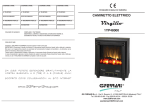
1
SORVALL
LEGEND MICRO 17/17R 21/21R
Instructions for use
How to use this manual
Use this manual to get acquainted with your
centrifuge and its accessories.
The manual helps you to avoid inappropriate handling.
Make sure to keep it always close to the centrifuge.
A manual that is not kept available cannot provide
protection against improper handling and thus
against damage to persons and objects.
This manual comprises chapters on
• Safety regulations
• Instrument description
• Transportation and hook-up the centrifuge
• Rotor program and accessories
• Use of the centrifuge
• Maintenance and care
• Troubleshooting
• Technical data
• Index
Overleaf you will find a graphic illustration of the control panel with a survey of
the most important functions
Please fold out
(only for instruments with refrigeration unit)
speed/RCF
rotor turns
temperature
run time
quick run
open lid
stop
start
“set“ keys
rpm/RCF
switch key
display
Note that “min-1” stands for “rpm” and
“x g” stands for “RCF”
“set“ keys
pre-temperature-regulation
(only for instruments with refrigeration unit)
Before switching on the centrifuge
please read this manual!
Control panel
Keys
Display panels
start:
start of the centrifuge
stop:
manually stop of a run
open lid:
open lid
(possible only with the instrument switched on and
standstill of the rotor)
Circulating light-points:
rotor turns
quick run:
short-term run up of the centrifuge as long as key
remains pressed
End:
„End“
Switch
Error codes:
flashing display with error code
Speed/RCF:
switching between speed and RCF display
Pre-temp:
pre-temp-function*
"set" keys:
stepwise increase/decrease of set-point values
Speed / RCF
Resting state:
current value (0) or pre-selected set-point value
During run:
present current value of speed or RCF
(after activation of switch key)
Run time
Resting/End:
current value (0) / “End”, or pre-selected set
point value
(in minutes, or "hd" for permanent operation)
Time selection/run: - remaining time till “0” in minutes
Permanent operation (hd):
„Quick run“:
- run time passed in seconds/ minutes
Short pressing of any of the "set" keys:
switch from current to pre-selected set-point value, signaled by
flashing display.
- run time passed in seconds/ minutes
Temperature*
according to:
current sample temperature in °C
(in temperature equilibrium)
* only for instruments with refrigeration unit
(Error codes (see „troubleshooting“section):
E-14:
E-22:
E-24:
E-31:
E-36:
E-46:
E-57:
E-60:
over temperature centrifuge chamber (> 50 °C)
troubled speed measurement
lid will not open
over temperature motor
over amperage or over voltage
lid was opened manually during run
imbalance
under temperature centrifuge chamber (< -20 °C)
Contents
Contents
For your safety............................................ 3
Handling the rotor .................................... 21
Safety instructions in this manual ............................ 3
Proper use................................................................ 4
Improper use ............................................................ 4
Centrifuging hazardous materials ............................ 4
Handling the centrifuge ............................................ 4
Conformity to current standards............................... 5
Rotor lid with a spring lock ................................. 21
Operation without rotor lid .................................. 22
Rotor lid with screw plug .................................... 23
Aerosol-tight application......................................... 24
Checking for aerosol-tightness........................... 26
Description of the instrument.................... 7
Pieces delivered....................................................... 7
Safety systems......................................................... 7
Properties ................................................................. 8
Before use................................................... 9
Where to install the centrifuge ................................. 9
Transport and installation the centrifuge.................. 9
Centrifuge with refrigeration unit .......................... 9
Mains connection ................................................... 10
Removing the transport protection......................... 10
Accessories .............................................. 11
Rotors for the LEGEND MICRO 17 ............................ 12
Rotors for the LEGEND MICRO 21 ............................ 14
Rotors for the LEGEND MICRO 17R ......................... 16
Rotors for the LEGEND MICRO 21R ......................... 18
Adapter................................................................... 20
Operation .................................................. 27
Switching on the centrifuge .................................... 27
Opening the lid ....................................................... 27
Closing the lid......................................................... 27
Installing the rotor................................................... 28
Loading the rotor .................................................... 30
Maximum load .................................................... 30
Filling the centrifuge tubes ................................. 30
Placing the tubes in the rotor.............................. 31
Entering parameters............................................... 32
Switching from speed to RCF display .................... 32
Selecting speed...................................................... 32
Entering the RCF value.......................................... 33
Concerning the RCF value ................................. 33
Selecting the run time ............................................ 34
Run time selection .............................................. 34
Continuous operation ......................................... 34
Setting the temperature.......................................... 35
1
Contents
Pretemp .............................................................. 36
Starting the centrifuge ............................................ 37
Changing the settings during the run ..................... 37
Stopping the centrifuge .......................................... 38
Preset run time ................................................... 38
Continuous operation ......................................... 38
Short-time centrifugation ........................................ 38
Removing the rotor................................................. 39
Audible alarm ......................................................... 39
Turning off the centrifuge ....................................... 40
WEEE Compliance:................................................ 40
Maintenance and care .............................. 41
Maintenance to be performed by the customer ..... 41
Cleaning.............................................................. 41
Cleaning the filter unit......................................... 42
Disinfection ......................................................... 43
Decontamination................................................. 45
Autoclaving ......................................................... 45
The Thermo Service offer ...................................... 46
Warranty conditions................................................ 46
Troubleshooting ....................................... 47
Mechanical emergency lid release......................... 47
Problems you can handle yourself ......................... 49
Contacting Service ................................................. 55
2
Technical data........................................... 57
Component parts.................................................... 57
The "Easycontrol" user interface ............................ 58
Performance........................................................... 59
Electrical connections............................................. 61
Appendix ................................................... 63
Speed / RCF diagram............................................. 65
Autoclaving protocol ............................................... 71
Index .......................................................... 73
For your safety
For your safety
Safety instructions in this manual
This symbol denotes potential hazards
to persons.
Sorvall® centrifuges are manufactured according to
current technical standards and regulations. Nonetheless, centrifuges may pose danger to individuals and
surrounding if
• they are not used as designed
• they are operated by untrained personnel
• their design is improperly changed
This symbol denotes potential damage
to the centrifuge or parts in its immediate surroundings.
Warning: hot surfaces
General danger area
Before switching on the centrifuge please
read this manual!
General hints are marked with this
symbol.
• the safety instructions are not followed
Therefore, personnel involved with operation and maintenance of the centrifuge must read and follow the safety
instructions.
In addition, the pertinent regulations for prevention of
accidents must be strictly followed.
This manual is an integral part of the centrifuge assembly and must be kept close at hand at all times.
When damages to the power cord or at
casing are noticed the centrifuge must
be set out of operation!
3
For your safety
Proper use
The centrifuge is designed to separate liquidsuspended materials having different densities and
particle size (maximum sample density is 1.2 g/cm³ at
maximum speed).
Improper use
During a run, a safety zone of 30 cm around the centrifuge must be maintained where neither persons nor
hazardous materials may be present.
The centrifuge may cause harm to its user or other
persons or may damage goods if safety measures are
not followed:
Centrifuging hazardous materials
being centrifuged, aerosol-tight bio-seals have to be
used.
For materials in a higher risk group, more than one
precaution is required.
• Should toxins or pathogenic substances enter the
centrifuge or its parts, you must perform appropriate procedures for disinfection (see "Maintenance
and care – Disinfection").
• Strongly corrosive substances that may cause
damage to materials and reduce the mechanical
strength of the rotor may be centrifuged only inside
protective tubes.
Handling the centrifuge
• The centrifuge is neither made inert, nor is it explosion-proof. Therefore never use the centrifuge in an
explosion-prone environment.
• Use only original accessories for the centrifuge.
The only exceptions are common glass or plastic
centrifuge tubes if they are approved for the rotor
speed and RCF values.
• Do not centrifuge explosive or flammable substances. The same holds for substances prone to
react violently with each other.
• Never use the centrifuge unless the rotor is properly
installed.
• Do not centrifuge toxic or radioactive substances or
pathogenic Micro-organisms without suitable safety
systems.
If Microbiological samples of risk group II (according to "Laboratory Bio-safety Manual" of WHO) are
• Strictly follow the rules and regulations for cleaning
and disinfection.
4
• You may use the centrifuge only with a properly
loaded rotor. You must not overload the rotor.
• If the rotor or the rotor lid shows signs of corrosion
or wear, you must stop using it.
For your safety
• Never open the lid manually if the rotor is still turning.
• You may use the emergency lid release only in
case of emergency, e.g. during an interruption of
power supply
(see chapter "Troubleshooting").
• Never use the centrifuge with an opened lid.
• Never use the centrifuge if the front panel has been
partially or totally removed.
• Changes in mechanical or electrical components of
the centrifuge may only be carried out by individuals authorized by Thermo.
Conformity to current standards
Sorvall® centrifuges are manufactured and tested according to the following standards and regulations
- for all voltages
• IEC 61010-1
IEC 61010-2-020
- for 120 V only
•
- for 230 V only
•
Please get acquainted with the details of the test standards from the technical data
5
For your safety
for your notes
6
Description of the instrument
Description of the instrument
Pieces delivered
The descriptions apply generally for all instrument
variants.
• rotor
• a special wrench for securing the rotor
• cable for mains connection
• this Manual
Safety systems
The LEGEND MICRO 17/21 and LEGEND MICRO 17R/21R
are equipped with several safety measures:
• Housing made of highly impact-resistant plastic;
Extra steel armor.
• Lid with window and lid latch with locking mechanism
You can open the centrifuge lid only when the centrifuge is switched on and the rotor is standing. You
can only start the centrifuge if the lid is properly
locked.
• Lid emergency release: Only in case of emergency,
e.g. the power supply is interrupted.
(see chapter „troubleshooting“)
Do not tamper with the safety systems!
7
Description of the instrument
Properties
The LEGEND MICRO 17/21 and LEGEND MICRO 17R/21R
are tabletop centrifuges designed for the use in biochemical and medical laboratories.
The preset speed is reached in seconds. You can also
spin samples for only a few seconds using the "quick
run" key ( ) if this is required for the task in question.
The extremely long-lived, maintenance-free induction
motor provides quiet and vibration-free operation even
at high speeds.
The user-friendly user interface „Easy control“ permits
easy handling. Prior to the run, when the centrifuge is
switched on and the lid is closed, the current values
are displayed and the pre-selected set point value can
be set. While the centrifuge is operating, the display
informs of current values or (by quickly pressing one of
or
) the pre-selected set point valthe “set” keys
ues for speed/RCF and runtime, as well as temperature in the refrigerated units. After the run, the speed
control panel displays "End".
8
or
repeatedly, you
If you press one of the keys
increase or decrease the corresponding pre-selected
set point value stepwise. If you press the chosen key
and hold it pressed, the respective chosen measurement value increases or decreases continuously, at
first slowly and, after a few seconds, at an accelerated
pace.
You can change the set values during operation.
"Quick run" operation
As long as the "quick run" key (
) is pressed, the
rotor is accelerated with maximum power (potentially
up to the maximum speed).
Before use
Before use
Where to install the centrifuge
The centrifuge may only be used indoors. Its location
must meet the following criteria:
• A safety zone of 30 cm around the centrifuge must
be maintained. Hazardous materials must not be
kept within this zone during centrifugation.
• The substructure must be stable and resonancefree. A good support is provided by a plane laboratory bench or a large laboratory carriage with casters that may be locked.
• In the area of 15 cm around the centrifuge a sufficient air circulation has to be ensured.
• The centrifuge must be protected from heat and
direct sunshine. The ultraviolet radiation may damage the housing.
• The installation site should be always well ventilated.
Transport and installation the centrifuge
Transport the centrifuge only in
the upright position, using the
special box provided with the instrument, and secure it properly.
Place the centrifuge carefully to
avoid damages.
Lift up the instrument only on the bottom
plate. Mind the weight of the centrifuge
during the transport!
(See „Technical data“)
Let someone assist you in carrying the
centrifuge!
Centrifuge with refrigeration unit
In order to allow the coolant to settle down in the compressor, the
instrument must be left idle at the
new location for approx. 1 hour.
9
Before use
Mains connection
Make sure that the mains supply and the frequency
meet the specifications printed on the centrifuge type
plate.
First turn the mains switch of the centrifuge off (press
"0") and only then connect the centrifuge with the
mains supply using the power cord supplied.
10
Removing the transport protection
Before using the centrifuge, make sure
that the rotor transport protection has
been removed!
Turn the instrument on at the power switch. Open the
and
centrifuge lid by pressing the "open lid" key
remove the transport protection for the rotor.
Check the free run of the rotor body by lightly turning it,
and make sure the rotor is tightly screwed and the rotor
lid is securely mounted.
Accessories
Accessories
You may choose from among a large variety of rotors
available as accessories.
In addition, there are sets of adapters and reduction
sleeves for diverse commercially available vessels.
Please consult our sales documentation for a complete
collection of accessories including technical data and
order numbers.
For more information you can visit our web site at
http://www.Thermo.com
11
Accessories
Rotors for the LEGEND MICRO 17
Table 1: Performance characteristics for LEGEND MICRO 17
rotor designation
Micro liter-rotor
24 x 2 ml
Micro liter-rotor
36 x 0,5 ml
Dual-rotor
18 x 2 ml / 0,5 ml
75003424
75003436
75003418
order no.
places / volume
maximum permissible load [ g ]
24 x 1.5 / 2 ml
36 x 0.5 ml
18 x 2 ml + 18 x 0.5 ml
24 x 4
36 x 0.5
18 x 4 + 18 x 0.5
-1
300
300
300
-1
maximum speed nmax [ min ]
13 300
13 300
13 300
maximum RCF value at nmax
17 000
15 600
16 800
acceleration / deceleration time [ s ]
11 / 12
9 / 10
11 / 12
radius maximum/ minimum
8.6 / 5.1
7.9 / 5.0
8.5 / 4.8
45
45
45
33
31
33
aerosol-tight *
yes
no
no
permissible temperature range
autoclavable (number of cycles)
-9 °C to +40 °C
121°C, (20 cycles)
-9 °C to +40 °C
121°C, (20 cycles)
-9 °C to +40 °C
121°C, (20 cycles)
minimum speed nmin [ min ]
angle
[ cm ]
[°]
heating of samples at nmax [ °C ]
relative to room temperature 23°C,
run time 1 hour
* Tested and approved by HPA, Porton-Down, UK – Please see the references in the chapter "Aerosoltight application"!
12
Accessories
Table 1: Performance characteristics for LEGEND MICRO 17
rotor designation
PCR-rotor
4x8
PCR-rotor
8x8
Haematocrit-rotor
order no.
75003440
75003489
75003473
places / volume
maximum permissible load [ g ]
4 x PCR-Strip
8 x PCR-Strip
4x4
8x4
(32 x 0,5)
(64 x 0,5)
24 x Blood capillary tubes 75 mm
24 x 0,2
-1
300
300
300
-1
maximum speed nmax [ min ]
13 300
13 300
13 300
maximum RCF value at nmax
13 100
13 800
16 800
acceleration / deceleration time [ s ]
10 / 11
7/8
10 / 11
radius maximum / minimum
6,6 / 4,7
7,0 / 4,4
2,0 / 8,5
45
60
90
31
31
34
aerosol-tight *
yes
no
no
permissible temperature range
autoclavable (number of cycles)
-9 °C to +40 °C
121°C, (20 cycles)
-9 °C to +40 °C
121°C, (20 cycles)
-9 °C to +40 °C
134°C
minimum speed nmin [ min ]
angle
[ cm ]
[°]
heating of samples at nmax [ °C ]
relative to room temperature 23°C,
run time 1 hour
* Tested and approved by HPA, Porton-Down, UK – Please see the references in the chapter "Aerosoltight application"!
13
Accessories
Rotors for the LEGEND MICRO 21
Table 2: Performance characteristics for LEGEND MICRO 21
rotor designation
Micro liter-rotor
24 x 2 ml
Micro liter-rotor
36 x 0,5 ml
Dual-rotor
18 x 2 ml / 0,5 ml
75003424
75003436
75003418
order no.
places / volume
maximum permissible load [ g ]
24 x 1.5 / 2 ml
36 x 0.5 ml
18 x 2 ml + 18 x 0.5 ml
24 x 4
36 x 0.5
18 x 4 + 18 x 0.5
-1
300
300
300
-1
maximum speed nmax [ min ]
14 800
14 800
14 800
maximum RCF value at nmax
21 100
19 300
20 800
acceleration / deceleration time [ s ]
13 / 13
10 / 11
11 / 12
radius maximum/ minimum
8.6 / 5.1
7.9 / 5.0
8.5 / 4.8
45
45
45
36
34
33
aerosol-tight *
yes
no
no
permissible temperature range
autoclavable (number of cycles)
-9 °C to +40 °C
121°C, (20 cycles)
-9 °C to +40 °C
121°C, (20 cycles)
-9 °C to +40 °C
121°C, (20 cycles)
minimum speed nmin [ min ]
angle
[ cm ]
[°]
heating of samples at nmax [ °C ]
relative to room temperature 23°C,
run time 1 hour
* Tested and approved by HPA, Porton-Down, UK – Please see the references in the chapter "Aerosoltight application"!
14
Accessories
Tabelle 2: Performance characteristics for LEGEND MICRO 21
rotor designation
PCR-rotor
4x8
PCR-rotor
8x8
Haematocrit-rotor
order no.
75003440
75003489
75003473
places / volume
maximum permissible load [ g ]
4 x PCR-Strip
8 x PCR-Strip
4x4
8x4
(32 x 0,5)
(64 x 0,5)
24 x Blood capillary tubes 75 mm
24 x 0,2
-1
300
300
300
-1
maximum speed nmax [ min ]
14 800
14 800
14 800
maximum RCF value at nmax
16 200
17 100
16 800
acceleration / deceleration time [ s ]
12 / 13
8/9
11 / 12
radius maximum / minimum
6,6 / 4,7
7,0 / 4,4
2,0 / 8,5
45
60
90
heating of samples at nmax [ °C ]
relative to room temperature 23°C,
run time 1 hour
33
32
35
aerosol-tight *
yes
no
no
permissible temperature range
autoclavable (number of cycles)
-9 °C to +40 °C
121°C, (20 cycles)
-9 °C to +40 °C
121°C, (20 cycles)
-9 °C to +40 °C
134°C
minimum speed nmin [ min ]
angle
[ cm ]
[°]
* Tested and approved by HPA, Porton-Down, UK – Please see the references in the chapter "Aerosoltight application"!
15
Accessories
Rotors for the LEGEND MICRO 17R
Table 3: Performance characteristics for LEGEND MICRO 17R
rotor designation
Micro liter-rotor
24 x 2 ml
Micro liter-rotor
36 x 0,5 ml
Dual-rotor
18 x 2 ml / 0,5 ml
75003424
75003436
75003418
order no.
places / volume
maximum permissible load [ g ]
24 x 1,5 / 2 ml
36 x 0,5 ml
18 x 2 ml + 18 x 0,5 ml
24 x 4
36 x 0,5
18 x 4 + 18 x 0,5
-1
300
300
300
-1
maximum speed nmax [ min ]
13 300
13 300
13 300
maximum RCF value at nmax
17 000
15 600
16 800
acceleration / deceleration time [ s ]
10 / 12
8 / 10
10 / 12
radius maximum / minimum
8,6 / 5,1
7,9 / 5,0
8,5 / 4,8
45
45
45
<0
<0
<0
aerosol-tight *
yes
no
no
permissible temperature range
autoclavable (number of cycles)
-9 °C to +40 °C
121°C, (20 cycles)
-9 °C to +40 °C
121°C, (20 cycles)
-9 °C to +40 °C
121°C, (20 cycles)
minimum speed nmin [ min ]
angle
[ cm ]
[°]
minimum temperature at nmax [ °C ]
relative to room temperature 23°C
* Tested and approved by HPA, Porton-Down, UK – Please see the references in the chapter "Aerosoltight application"!
16
Accessories
Table 3: Performance characteristics for LEGEND MICRO 17R
rotor designation
PCR-rotor
4x8
PCR-rotor
8x8
Haematocrit-rotor
order no.
75003440
75003489
75003473
places / volume
maximum permissible load [ g ]
4 x PCR-Strip
8 x PCR-Strip
4x4
8x4
(32 x 0,5)
(64 x 0,5)
24 x Blood capillary tubes 75 mm
24 x 0,2
-1
300
-1
maximum speed nmax [ min ]
13 300
13 300
13 300
maximum RCF value at nmax
13 100
13 800
16 800
acceleration / deceleration time [ s ]
9 / 12
6/8
9 / 11
radius maximum / minimum
6,6 / 4,7
7,0 / 4,4
2,0 / 8,5
45
60
90
<0
<0
<0
aerosol-tight *
yes
no
no
permissible temperature range
autoclavable (number of cycles)
-9 °C to +40 °C
121°C, (20 cycles)
-9 °C to +40 °C
121°C, (20 cycles)
-9 °C to +40 °C
134°C
minimum speed nmin [ min ]
angle
[ cm ]
[°]
minimum temperature at nmax [ °C ]
relative to room temperature 23°C
300
* Tested and approved by HPA, Porton-Down, UK – Please see the references in the chapter "Aerosoltight application"!
17
Accessories
Rotors for the LEGEND MICRO 21R
Table 4: Performance characteristics for LEGEND MICRO 21R
rotor designation
Micro liter-rotor
24 x 2 ml
Micro liter-rotor
36 x 0,5 ml
Dual-rotor
18 x 2 ml / 0,5 ml
75003424
75003436
75003418
order no.
places / volume
maximum permissible load [ g ]
24 x 1,5 / 2 ml
36 x 0,5 ml
18 x 2 ml + 18 x 0,5 ml
24 x 4
36 x 0,5
18 x 4 + 18 x 0,5
-1
minimum speed nmin [ min ]
300
300
300
-1
maximum speed nmax [ min ]
14 800
14 800
14 800
maximum RCF value at nmax
21 100
19 300
20 800
acceleration / deceleration time [ s ]
12 / 13
9 / 11
11 / 13
radius maximum / minimum
8,6 / 5,1
7,9 / 5,0
8,5 / 4,8
45
45
45
<4
<4
<4
aerosol-tight *
yes
no
no
permissible temperature range
autoclavable (number of cycles)
-9 °C to +40 °C
121°C, (20 cycles)
-9 °C to +40 °C
121°C, (20 cycles)
-9 °C to +40 °C
121°C, (20 cycles)
angle
[ cm ]
[°]
minimum temperature at nmax [ °C ]
relative to room temperature 23°C
* Tested and approved by HPA, Porton-Down, UK – Please see the references in the chapter "Aerosoltight application"!
18
Accessories
Table 4: Performance characteristics for LEGEND MICRO 21R
rotor designation
PCR-rotor
4x8
PCR-rotor
8x8
Haematocrit-rotor
order no.
75003440
75003489
75003473
places / volume
maximum permissible load [ g ]
4 x PCR-Strip
8 x PCR-Strip
4x4
8x4
(32 x 0,5)
(64 x 0,5)
24 x Blood capillary tubes 75 mm
24 x 0,2
-1
300
-1
maximum speed nmax [ min ]
14 800
14 800
14 800
maximum RCF value at nmax
16 200
17 100
16 800
acceleration / deceleration time [ s ]
11 / 13
7/9
10 / 12
radius maximum / minimum
6,6 / 4,7
7,0 / 4,4
2,0 / 8,5
45
60
90
<4
<4
<8
aerosol-tight *
yes
no
no
permissible temperature range
autoclavable (number of cycles)
-9 °C to +40 °C
121°C, (20 cycles)
-9 °C to +40 °C
121°C, (20 cycles)
-9 °C to +40 °C
134°C
minimum speed nmin [ min ]
angle
[ cm ]
[°]
minimum temperature at nmax [ °C ]
relative to room temperature 23°C
300
* Tested and approved by HPA, Porton-Down, UK – Please see the references in the chapter "Aerosoltight application"!
19
Accessories
Adapter
Table 5: Adapter
Adapter for
Micro Liter Rotor 7500 3424
Dual-rotor
7500 3418
max. tube
dimensions
1)
d x length
[ mm ]
reduction sleeve PCR
reduction sleeve
reduction sleeve
6.2 x 20
8 x 43.5
6 x 46
1)
20
d = diameter
tube capacity
[ ml ]
0,2
0.5 / 0,6
0.25 / 0.4
number
per set
24
24
24
color
no. of
order
grey
turquoise
red
7600 3750
7600 3758
7600 3759
Handling the rotor
Handling the rotor
Rotor temperature
The rotors are only to be used within
the temperature range from - 9°C to
+40°C. Pre-tempering in a freezer
below - 9°C is vorbidden.
Rotor lid with a spring lock
Opening
The rotor lid is held on the central rotor nut integrated
into the rotor
Handhold
Lifetime of the rotor
There is no limitation on the service life of the high
performance rotors. However please observe the following due to safety reasons:
Rotors and accessories made of
plastic should not be exposed to
direct sunlight and UV radiations.
If the rotor shows signs of discoloration, deformation or wear, or imbalance it has to be replaced straight
away!
Unlocking-button
The rotor lid is opened by pressing the red unlockingbutton in the central handhold of the rotor lid.
The lid can be lift-off easy.
21
Handling the rotor
- Closing
For closing the rotor place the rotor lid centrically on
the rotor nut.
Press the rotor lid down now until the lock is audiovisually locked
If the lid will not lock or it locks only with difficulty, the
seals should be checked for proper fit and fouling and if
necessary cleaned and softly lubricated. Likewise the
lid mechanics is to be checked for fouling and proper
functionality.
Damaged parts must be exchanged immediately.
Operation without rotor lid
If you are going to operate the rotor without the rotor lid
the aerosol-seals must be removed prior to use.
Aerosol-seals
Always verify the tight fit of the
rotor lid by pulling the lid after
locking it!
During the centrifugation without a
rotor lid the aerosol seals are not
longer fixed and may cause serious
damage to the centrifuge!
During the operation with opened
tube caps, they can break away and
cause damages.
22
Handling the rotor
Rotor lid with screw plug
For this kind of rotor the rotor lid will be held centrically
on the rotor collar.
These rotors are not designed for
aerosoltight applications!
The O-Ring in the rotor collar provides only for tight fit of screw plug.
The external lid lip can not be sealed
for these rotors.
To close the rotor, place the rotor lid centrically on the
rotor nut. By clockwise turning of the lid-handle the
rotor lid is fixed.
Please always verify the fixed
anchorage of the rotor lid!
23
Handling the rotor
Aerosol-tight application
Only with the designated rotors!
Tubes are only to be filled to a level where the sample
does not reach the brim of the tubes during centrifugation.
See the rotor tables from page 12
Aerosol-tight rotors and tubes are only
to be opened in an approved safety
work bench when centrifuging dangerous samples!
It is indispensable to observe the
maximum permissible filling quantities!
Attention:
Please check that your sample tubes are suitable for
the centrifugal application desired:
- Gravitation fields up to 21100xg,
- temperature in uncooled devices maximum
approx. 15 K above room temperature.
24
Please observe the permissible filling volumes!
Nominal volume:
Permissible volume:
2.0 ml
1.5 ml
1.5 ml
1.0 ml
2
/3 nominal volume
others
-
Aerosol-tight application
not with open tube caps!
Handling the rotor
Correct operation when filling the sample tubes and
closing the rotor lid are prerequisites for aerosol biocontainment.
The following steps have to be carried out:
•
Lubricate the seals before inserting them
(lubricant order no. 76003500)
•
Press the smaller V-seal into the groove of the
rotor collar (a).
•
Insert the seal (C-profile) in the outer groove of the
rotor body (b).
Prior to each application, the seals in
the rotors have to be checked for
correct fit, abrasion or damage and
have to be slightly greased.
Replace damaged seals immediately!
Use only the special lubricant
7600 3500 to grease the seals!
A set of spare seals is supplied with the rotor and can
be ordered separately as spare seal set 75003405.
Pay attention after loading the rotor to
safe closing of the rotor cover!
Replace damaged or dulled rotor
lids promptly!
25
Handling the rotor
Checking for aerosol-tightness
The checking of the rotor type and bucket was done
according to the dynamic Microbiological test procedure with regard to EN 61010-2-020 appendix AA.
The aerosol-tight bio-containment of the rotor mainly
depends on proper handling!
Check the aerosol-tight bio-containment
of your rotor whenever necessary!
It is very important that all the seals and
seal-surfaces are carefully inspected for
wear and damages like cracks, scratches
and embrittlement!
26
For a quick test one can check the fixed angle rotors
according to the following procedure:
•
Slightly grease all seals.
•
Fill the rotor with approx. 10 ml carbon dioxide
mineral water.
•
Close the rotor according to the respective handling instructions.
•
Due to the shaking, the carbon dioxide of the water
is released, and an overpressure is built up. Do not
press the lid simultaneously.
•
Leaks are recognized by humidity release and
audible disinflation of gas mix.
•
In case of leakage the aerosol-seals have to be
replaced and the leakage check has to be repeated.
•
Dry rotor, rotor lid and lid seal.
Operation
Operation
Switching on the centrifuge
Set the main power switch of the instrument.
For a couple of seconds the following reading appears
in the control panel: (the temperature display field only
for cooled instrument)
Opening the lid
For activating the lid release the centrifuge
must be connected to mains and switched
on!
To open the lid press the „open-lid“-button
The display reads:
The display shows that the instrument is going through
an internal check of its software.
After this check, the display switches into the current
value mode. The speed and remaining run time show
0.
The refrigeration unit display shows the current temperature of the sample. (Prior to the start of the centrifuge, the display usually shows the temperature of the
rotor chamber).
The following figure gives an example of possible readings of the display. A detailed description of possible
settings is given below in this chapter.
.
(Emergency release in case of malfunction or power
failure: see chapter "Troubleshooting")
Closing the lid
The centrifuge lid is locked by slightly pressing down
the front part of the lid.
Do not slam the lid!
27
Operation
Installing the rotor
Improper or improperly combined
accessories may cause severe damage to the centrifuge!
The centrifuge rotors approved are detailed in the
chapter “Accessories". Use only rotors listed for this
instrument.
To insert the rotor, you need the special wrench delivered with the instrument (see chapter "accessories”).
You may insert the rotor only when the temperature
difference of the drive and the rotor drive shaft
achieves maximum 20 °C. Otherwise the rotor may jam
during the installation.
The installation of a clamping rotor
can lead to demages of the drive
shaft and rotor!
28
Proceed as follows:
1. Open the centrifuge lid and make sure that the
rotor chamber and the rotor are clean. Remove
eventual dust, foreign material or sample residues.
The thread and the O-Ring on the motor shaft must
be in perfect condition.
2. Turn the rotor so that the notch for engaging the
drive shaft points downward.
3. Place the rotor on top of the drive shaft so that the
notch of the rotor is located precisely above the retaining pin. (There a two bars in the labelling on the
upper side of the rotor indicating the position of the
notch). These bars make the positioning easy.
Operation
4. Press the rotor gently down until it stops.
5. Grip the rotor tightly and use the provided rotor
wrench to tighten up the rotor.
Do not push the rotor down using
force.
If the rotor can not be tightened,
you have to remove it carefully,
align the notch and the retaining
pin again and re-install it.
6. Place the rotor lid onto the rotor, and attend to the
tight fit of the rotor.
Check tight placement of the rotor regularly
and re-tighten the rotor as needed.
Attention at the replacement of the
rotor after the centrifugation!
Rotor drive and motor end shield
may be hot (>55°C).
29
Operation
Filling the centrifuge tubes
Loading the rotor
Maximum load
Overloading may cause the rotor
to explode!
Exploding parts may severely
damage the centrifuge!
The centrifuge can reach high rotational speeds implying enormous centrifugal force. The rotors are designed in a way warranting sufficient residual strength
even at the highest permissible speed.
However, this safety system presupposes that the
maximum permissible load of the rotor is not exceeded.
If you wish to centrifuge samples that together with the
adapters exceed the maximum permissible load, you
must either reduce the sample volume or calculate the
permissible speed nperm according to the following formula:
n
perm
30
=n
max
∗
maximum permissible load
actual load
Please note that plastic sample vessels only
have a limited service life - particularly when
used at maximum performance (rpm or temperature) - and must be replaced as necessary!
Check carefully whether your sample vessels are permissible for the
respective g value and reduce the
speed if necessary.
The smaller the centrifuge imbalance, the better the
separation, because separated zones are no longer
perturbed by vibration. It is therefore important to balance the centrifuge tubes as well as possible.
To minimize imbalance you should fill the tubes as
evenly as possible. You can achieve this by eye. However, you must nonetheless ensure that opposite tubes
are filled to the same level.
Operation
Placing the tubes in the rotor
The rotor must be loaded symmetrically. When loading
the rotor only partially, you must ensure that opposite
bores always receive tubes of equal weight (when centrifuging a single sample, place a centrifuge tube e.g.
filled with water opposite). The following figure gives
examples for proper loading.
Uneven loading may lead to damage of
the rotor and centrifuge in extreme
cases. Imbalance not only causes a
noisy run, but also causes premature
abrasion of the drive.
1
9
ST
IN
8
HERAEUS
6
7
1
9
m
rp
ST
IN
6
m
rp
7
8
HERAEUS
IN
8
HERAEUS
6
m
rp
5
5
4
3
1
IN
9
ST
d
8
HERAEUS
6
m
rp
5
4
improperly loaded rotors
11
0
5
12 13 14 1
NTS
ma x
IN
9
ST
1
RU
ME
loa
8
HERAEUS
6
7
1
d
5
12 13 14 1
RU
ME
11
0
2
23
max 1
24 1
00
30
2
5
#
rp
m
6
NTS
ma x
loa
1
d
5
12 13 14 1
RU
ME
NTS
ma x
loa
1
d
2
33
24
4
11
0
7
00
30
2
7
1
1
loa
9
ma x
IN
NTS
ST
5
12 13 14 1
RU
ME
8
11
HERAEUS
max 1
24 1
0
6
4
1
d
m
9
loa
rp
7
1
ma x
ST
NTS
5
5
5
12 13 14 1
RU
ME
4
4
11
0
1
1
d
9
loa
ST
ma x
IN
NTS
8
5
12 13 14 1
RU
ME
7
11
0
HERAEUS
1
d
6
loa
23
These examples are to be applied to the other rotors in
an analogous manner!
When you have loaded the tubes, close the rotor lid.
9
p p 1/
m
ma x
3
g
1
18 19 20 2
rp
NTS
2
2
00
30
2
x4
#
5
5
12 13 14 1
RU
ME
33
24
#
max 1
24 1
24
17
6
4
11
6
3
9
p p 1/
00
30
2
0
g
max 1
24 1
1
18 19 20 2
2
23
x4
#
33
24
24
6
2
17
9
p p 1/
3
6
g
2
00
30
2
1
18 19 20 2
#
max 1
24 1
x4
96
p p 1/
23
6
9
p p 1/
3
2
23
24
g
1
18 19 20 2
x4
2
g
1
18 19 20 2
x4
00
30
2
#
24
17
24 1
6
6
max 1
9
p p 1/
2
23
33
24
2
3
2
33
24
17
24
17
g
#
33
24
1
18 19 20 2
6
00
30
x4
9
p p 1/
max 1
24 1
24
g
1
18 19 20 2
x4
23
17
24
17
2
6
6
33
24
2
6
6
2
3
Close the lid of the centrifuge by lightly pressing it down. The centrifuge lid must be locked
audibly so that it cannot be manually reopened afterwards.
properly loaded rotors
31
Operation
Entering parameters
Switching from speed to RCF display
Upon turning on the centrifuge, the speed display is
set.
you can switch to the
By activating the selection key
RCF- value or change between rpm and RCF displays.
Selecting speed
The centrifuge speed can be set to a minimum of 300
rpm. The maximum speed depends on the centrifuge
version).
You can adjust the speed in 100 rpm increments.
Proceed as follows:
(for increase) or
1. Press one of the "set" keys
(for decrease) in the field “speed” of the control
panel to enter the pre-selected value mode (cf.
foldout leaf in the cover):
32
By pressing the key
briefly, you increase or
decrease the speed in one
step (of 100 rpm).
This option is supposed to
be used for small changes
and fine tuning.
2. If you hold the key pressed, the display changes
continuously at first slowly and after a few seconds
at an accelerated pace to the higher or lower values.
3. Release the key as soon as you reached the desired value and fine tune if necessary by repeatedly
brieftly pressing the selected key). The first digit behind the decimal point flashes for a few seconds
and then switches permanently inro the current
value mode. The new pre-selected speed is now
stored.
Operation
Entering the RCF value
You can adjust the RCF pre-selected value in steps of
100 g. The setting of pre-selected value is entered
analogously to the speed.
The RCF value can be set to a minimum of 100xg. The
setting of a maximum RCF depends on the type of
centrifuge.
The displayed RCF value is always corresponding to the maximume of centrifuge
radius of the Micro liter rotor 24 x 2ml
(7500 3424).
For other rotors please use the formula beneath or
follow the enclosed speed/RCF diagrams.
Concerning the RCF value
The relative centrifugal force (RCF) is given in multiples of the earth gravity g. It is a dimensionless number
value that allows one to compare the efficiency of
separation or sedimentation of diverse instruments,
since it is independent of the instrument used. The only
values entered in the equation are radius and speed of
centrifugation:
2
⎛ n ⎞
RCF = 11.18 ∗⎜
⎟ ∗r
⎝ 1000 ⎠
r = radius of centrifugation in cm
n = speed in rpm
The maximum RCF value refers to the maximum radius of the vessel bore.
Please note that this value becomes lower
depending on the tubes and adapters used.
Mind the rounding difference!
Due to limited display digits there is a need
to round the values. The direct comparison
between the two values speed and RCF is
therefore restricted.
You may take this into account when calculating the
RCF value for your application.
33
Operation
Selecting the run time
You can select a run time between 1 and 99 min or
continuous operation [hd].
Run time selection
To predetermine the fixed run time, proceed as follows:
1. Press one of the "set" keys
(for increase) or
(for decrease) in the field “time” of the control panel
to enter the pre-selected value mode (cf. foldout
leaf in the cover):
By pressing the selected key
briefly, you increase or decrease
the preset run time in steps of 1
min. This option is supposed to be
used for small changes and fine
tuning.
2. If you keep the key pressed, the display changes at
first slowly and after a few seconds at an accelerated pace to the higher or lower values.
34
3. Release the key as soon as you have reached the
desired value and fine tune if necessary by repeatedly briefly pressing one of the keys. The run time
display flashes for a number of seconds, then
changes to permanent display of the current value
mode. The new pre-selected run time is now stored.
Continuous operation
To operate the centrifuge in the continuous mode, you
until the display changes to „hd“
must press the key
(for "hold").
In this mode the centrifuge runs
until you stop the run by manually
pressing the „Stop“-button .
Please note that the lifetime of particularly
plastic rotor tubes is limited. Continuous
operation (extended use) may cause damage to them!
Operation
Setting the temperature
To determine the sample temperature for instruments
with refrigeration unit, operate as adviced:
(for increase) or
1. Press one of the "set" keys
(for decrease) in the the field “temperature” of the
control panel to enter the pre-selected value mode
(cf. foldout leaf in the cover):
By pressing the key briefly, you
increase or decrease the temperature in steps of 1 °C.
3. Release the key as soon as you are close to the
desired value and fine tune if necessary by repeatedly briefly pressing the key. The display flashes for
a few seconds and then turns to permanent display
of the current value mode. The new pre-selected
temperature is now stored.
The refrigeration starts operating after closing the centrifuge lid, at once if the pre-selected temperature is
below the current temperature of the rotor chamber.
This option is supposed to be used for small changes
and fine tuning.
2. If you keep the key pressed, the display changes at
first slowly and after a few seconds at an accelerated pace to the higher or lower values.
35
Operation
Pretemp
The pretemp-function allows quick and easy tempering
of the unloaded rotor.
only
After calling the function by pressing the key
the desired temperature still must be chosed.
(If any other key is pressed, the pretemp function will
be quit).
the rotor will be operAfter activating the „start“ key
ated at optimal speed until the the desired temperaturen is reached.
key indicates operation at the
An LED above the
activated pretemp function.
36
If you wish to change the temperature of your samples,
please consider that the time required for temperature
adjustment is prolonged. The farther apart initial and
final temperature, the longer it takes for the temperature to adjust.
The temperature reading does not give the
change in the temperature of the sample
(the temperature display reading is delayed
with respect to the /actual/ sample temperature change). You can neither witness the
heating nor the cooling of the samples directly. For critical applications you should
take other precautions to ensure that the
desired temperature is actually reached and
maintained (e.g. by measuring the temperature immediately after the centrifugation run).
Operation
Starting the centrifuge
Changing the settings during the run
Once the rotor is properly installed, the main switch
turned on and the lid closed, you can start the centrifuge.
in the control panel. The centriPress the "start" key
fuge accelerates to the pre-selected value, simultaneously, the run time display starts counting backwards
per minute. If the remaining run time of one minute is
under-run, the time display switches to counting seconds.
You can change the settings while the rotor is spinning.
Trough a one-time pressing of any key of the control
panel, the current value will switch into the preselecting value mode.
The rotating light in the speed display indicates that the
centrifuge is running.
During continuous operation “hd”, the run time is displayed in forward run. Display first starts per second,
after one minute the display switches to minutes.
The to be altered value flashes, and can then be
changed. Once the display switches into the current
value mode after completion of the entered values, the
new values are activated.
The values are taken over by press the "start" key
immediately.
.
During the run, you cannot open the lid.
37
Operation
Stopping the centrifuge
Short-time centrifugation
Preset run time
Normally the run time has been pre-selected, and all
you have to do, is to wait until the centrifuge terminates
the run automatically.
As soon as the speed is down to zero, the display
reads "End". By pressing the "open lid" key , you can
now open the lid and remove your centrifugation samples.
You can stop the centrifuge at any time by pressing the
.
"stop“ key
For short-term operation, the centrifuge is equipped
with the "quick run" function.
Short-term centrifugation is started by pressing the
continuously; it stops as soon as the
"quick run" key
key is released.
In this mode the centrifuge accelerates with full power
up to the maximum speed unless you release the
"quick run" key .
The pre-selected speed is ignored.
Continuous operation
If you have chosen continuous operation, you must
in
stop the centrifuge manually. Press the "stop" key
the control panel. The centrifuge starts braking at once
and stops within a few seconds. The display reads
"End", the electrical lid unlocking mechanism is available. You can now open the lid by pressing the "open
and remove your centrifugation samples.
lid" key
38
The centrifuge accelerates to the
maximum speed.
Check carefully whether you have to
maintain a specific speed limit for
your application.
first the
During the activating of the "quick run" key
time is counted forward in seconds. After 60 seconds
the display changes to the minute cycles.
Operation
Removing the rotor
Audible alarm
To remove the rotor you have to proceed in the reserve
order as at the installation of the rotor.
In case of contamination you can remove the rotor from
the drive shaft without opening the aerosol lid. Then
you can open the removed rotor e.g. in a safety work
bench and decontaminate it.
Accompanying all error messages, a warning signal is
given out which can be silenced upon pressing any
key.
By default there is an acoustic signal at the end of any
centrifugation run. You have the possibility to switch off
this signal. For this, you have to press the „speed/ RCF
while switching on the centrifuge.
switch key
1. Open the centrifuge lid.
2. Unscrew the rotor nut with the provided. Turn the
rotor nut counterclockwise.
3. Grab the rotor centrically and carefully pull it perpendicularly off the drive shaft. Make sure not to tilt
it.
Depending on the pre-selected mode the display
shows the following signs: “Snd” “on” or „Snd“ „oF“.
or
in the field “time” the
By pressing the set keys
acoustic signal function can be turned off or on. Subthe new setting
sequently, by pressing the stop key
will be activated.
39
Operation
Turning off the centrifuge
WEEE Compliance:
The centrifuge is turned off by switching the main
switch into the "0"position.
This product is required to comply with the European
Union`s Waste Electrical & Electronic Equipment
(WEEE) Directive 2002/96/EC. It is marked with the
following symbol:
The main power switch should be turned off
after a complete centrifugation run. Without
motor deceleration, it takes much longer
until the rotor comes to a halt.
The centrifuge is equiped with a special
switch for balancing potential voltage discrepancies in the power grid. After pressing
the mains switch the display therefore may
still flash up to 10 seconds.
The opening of the centrifuge lid is only
possible by means of „lid open“-key
while the centrifuge is switched on!
40
Thermo has contracted with recycling/disposal companies in each EU Member State, and this product should
be disposed of or recycled through them.
Further information on Thermo`s compliance with these
Directives, the recyclers in your country, and information on Thermo products which may assist the detection (EU-standard on the limitation of hazardous
substances) of substances subject to the RoHS Directive are available at
www.thermo.com/WEEERoHS.
Maintenance and care
Maintenance and care
Maintenance to be performed by the
customer
For the protection of persons, environment and material you are obliged to clean the centrifuge regularly
and to disinfect it if necessary.
Unsuitable cleaning agents or disinfection procedures may damage
the centrifuge and its accessories!
Before using cleaning agents or
disinfection procedures not recommended by the manufacturer, the
user have to make sure by consulting the manufacturer, that the procedure foreseen does not cause any
damages to the instrument!
Instruments with refrigeration unit:
If a strong ice sheet is present in the internal
chamber, be sure to remove all condensate
after defrosting!
Cleaning
Pull mains plug before cleaning the
instrument!
Clean the casing, the rotor chamber, the rotor and the
accessories regularly and in case of need. This is indicated both for reasons of hygiene and to prevent corrosion due to contamination sticking to the instrument
and its accessories.
Clean them with mild agents of pH values ranging from
6 to 8.
Immediately after cleaning, dry the aluminum parts or
put them into a warm-air dryer at a temperature not
exceeding 50°C.
During cleaning liquids and especially organic solvents should not
come into contact with the drive
shaft and the ball bearing.
Organic solvents may decompose
the lubricant of the motor bearing
causing the drive shaft to lock.
41
Maintenance and care
Please clean the venting slots regularly!
To protect the refrigeration unit, the cooled devices are
equipped with an air filter unit.
Depending on the environment situation it is
recommended to clean the filter at least every three
months.
Sucking grid
Disconnect the centrifuge from mains
switch before cleaning the venting
slots and the filter unit.
Pull the cord!
Cleaning the filter unit
To remove the filter unit pull the centrifuge to the edge
of the table.
Pull the clip below the sucking grid down and remove
the filter unit completely by pulling down.
A soft cloth now easily removes the cumulated dust.
42
Front
Clip of the filter unit
Please observe the labeling „front“ and „rear“ on the
clip when inserting the filter into the centrifuge! “Front”
must show to the front of the centrifuge.
Push the filter upwards into the slot until the clip locks
in the bottom plate.
Maintenance and care
Disinfection
If a centrifuge tube containing infectious material
leaks, during a centrifugation run, you have to disinfect
immediately the rotor, and/or also the centrifuge.
Infectious material could enter the centrifuge if spills or tube breakage occur.
Danger of infection may occur upon contact!
Take appropriate protective measures for
personnel!
Mind the permissible filling volumes and
loading limits for the tubes!
In case of contamination the operator has
to make sure, that no further persons are
jeopardized!
Contaminated parts have to be decontaminated immediately.
If required further protective measures
have to be initiated.
Rotor and rotor chamber must be treated with a neutral, universal desinfectant. Best suited for this purpose
are disinfectant sprays, ensuring that all rotor and accessory surfaces are covered evenly.
Please note the safety measures
and handling hints when applying
these substances!
You may disinfect the rotor and the accessories as
described in the following section. Be sure to follow the
pertinent safety procedures for handling infectious
material.
1. Unplug mains cord.
2. Unscrew the rotor from the shaft.
3. Grab the rotor with both hands and pull it perpendicularly off the drive shaft.
4. Remove the centrifuge tubes and adapters, and
disinfect them or dispose of them as necessary.
43
Maintenance and care
5. Treat the rotor and the rotor lid according to the
instructions given for the disinfectant (soaking in
liquid or spraying). You must strictly observe the
specified action times!
6. Turn the rotor head down and drain off the disinfectant. Thereafter thoroughly rinse rotor and lid with
water.
7. Dispose of the disinfectant according to valid regulations.
8. Aluminum rotors have to be treated with anticorrosive protective oil subsequently.
9. All seals have to be lubricated again.
44
Disinfection with bleaching lye
These agents contain highly aggressive hypochlorites and must
not be used with aluminum rotors!
The following precautionary measures are to be taken
for extensive protection of the plastic rotors:
1. Avoid high temperatures!
The bleaching solution and the rotor should not be
warmer than ca. 25 °C.
2. Do not let the bleaching solution act longer than
absolutely necessary!
3. After disinfection, rinse the rotor thoroughly with
distilled water and allow drying.
4. All seals have to be lubricated again.
Maintenance and care
Decontamination
For general radioactive decontamination, use a solution of equal parts of 70% ethanol, 10% SDS and water. Follow this with ethanol rinses, then de-ionized
water rinses, and dry with a soft absorbent cloth. Dispose of all washing solutions in appropriate radioactive
waste containers!
The rotor must be cleaned and rinsed with distilled
water before being autoclaved. Remove the rotor lid,
the centrifuge tubes and the adapters. Place plastic
rotors on an even surface to avoid deformation.
Chemical additives to the steam are not
permitted.
Autoclaving
Check whether autoclaving is permitted!
You may autoclave the rotor, rotor lid and the adapters
at 121 °C.
Maximum permissible autoclaving cycle:
20 minutes at 121 °C.
Never exceed the maximum permissible values for autoclaving
temperature and autoclaving time.
Should the rotor show signs of
wear or corrosion, you must stop
using it!
For safety reasons, the plastic rotors
and rotor lids must only be subjected
to a maximum of 20 autoclaving
cycles!
45
Maintenance and care
The Thermo Service offer
Warranty conditions
Thermo recommends annual servicing of the centrifuge
and the accessories by authorized customer service or
trained professionals. The customer service personnel
inspects:
The warranty period starts with the day of delivery.
Within the warranty period the centrifuge is repaired or
replaced free of cost if there are provable faults in materials or workmanship.
Conditions for a warranty are:
• the electrical installations
• the suitability of the location
• the lid lock mechanism and the safety circuit
• the rotor
• the rotor fastening and the drive shaft
Defective material is exchanged. The customer service
additionally cleans the rotor chamber.
Thermo offers inspection and service contracts covering it. Inspection costs are charged as flat-rate contracts.
Necessary repairs are carried out free of cost within the
warranty conditions, and against payment after expiration of the warranty period.
46
• the centrifuge is used according to this instructions
of use
• mounting, extensions, settings, alterations or repairs are carried out exclusively by personnel authorized by Thermo
• the required maintenance and care procedures are
carried out regularly.
Troubleshooting
Troubleshooting
Mechanical emergency lid release
In case of a power failure you cannot open the lid normally using the electric emergency release. To permit
unloading even in this case, the centrifuge is equipped
with a hand operatated lid unlocking system. However,
you may use this system only in case of emergency.
1. Make sure the rotor stands still. (control window).
2. Unplug the mains cord.
3. Push a small straight wire of a length of approx.
7cm (e.g. a bended paper clip etc.) through the hole
located in the middle above the display, at the
chamber edge.
Rotor can spin at high speed!
Touching it may cause severe injuries!
Always wait for several minutes until
the rotor has come to a complete
standstill without deceleration. Without power the brake does not function, and braking takes much longer
than normal!
Should it be necessary to open the lid manually, proceed as follows using an appropriate / special tool:
47
Troubleshooting
4. Gently press the centrifuge lid down to disengage
the lid-latch.
5. While pressing down the lid push the wire down
further until you hear and feel the lid-latch unlocking. Remove the auxiliary tool and open the centrifuge lid.
6. In case the rotor still turns, close centrifuge lid immediately and wait until it has come to a complete
standstill.
Never brake the rotor using your
hands or tools!
7. As soon as the rotor stands still, remove your samples and close the centrifuge lid.
48
Troubleshooting
Problems you can handle yourself
If problems other than those described in the following tables arise, you must consult your nearest
authorized service.
Error
Displays remain dark
Displays fail briefly.
Centrifuge lid cannot be
opened.
Symptom
Possible causes and corrective measures
The drive stops.
Mains voltage disconnection
The rotor stops without
deceleration. The lid
cannot be opened.
1. Is the mains switch turned on?
2. Check the mains connection.
If the mains connection is ok, contact the service
representative.
The drive stops suddenly.
Main connection was briefly interrupted
The rotor stops without
deceleration.
1. Turn off mains switch.
2. Check whether the mains power cord is connected
properly.
3. Restart the centrifuge.
Pressing the "open lid" key
has no effect.
Centrifuge lid not correctly engaged or lid warped.
1. Check if mains connection is working and the instrument
is switched on (display is lit).
2. If this is unsuccessful, you may open the centrifuge lid
using the mechanical emergency lid release
(see page 47).
49
Troubleshooting
Error
Symptom
Possible causes and corrective measures
–
Exceptionally running
noise.
Imbalance.
1. Stop the centrifuge by pressing the "stop" key, in case of
emergency, unplug mains power cord.
2. Wait until the centrifuge comes to a complete stop.
3. Check whether the rotor is properly loaded.
4. Check whether a broken tube, damage to the rotor or
motor is responsible for the run noise.
If you cannot locate and solve the problem yourself, contact a
service representative
Display "oP" appears
although lid is closed.
Will not start.
“Lid”
Rotor stops with
deceleration to standstill.
Centrifuge lid not properly closed
- Open the lid and repeat locking procedure.
If you cannot locate and solve the problem yourself, contact a
service representative.
Centrifuge lid was opened manually during the run.
- Close centrifuge lid immediately
The instrument phases out with deceleration.
For further centrifugation, you have to switch the instrument
off and switch it on again.
50
Troubleshooting
Error
Symptom
„bAL“
The rotor stops with
deceleration.
Possible causes and corrective measures
Imbalance switch releases.
1. Open the instrument by pressing the “lid open”
in case.
2. Check whether the rotor is properly loaded.
3. Check whether a broken tube or a damage to the rotor
release the imbalance switch.
If you cannot locate and solve the problem yourself, contact a
service representative.
E-01
|
Rotor stops without
deceleration to standstill.
Internal program error.
E-13
Instrument cannot be
operated.
If the error persists, contact service representative.
E-14
Rotor stops with
deceleration to standstill.
Overtemperature in the centrifuge chamber.
Instrument cannot be
operated.
Switch the instrument off and on again.
Switch the centrifuge off and turn it on again after approx. one
minute.
If the error persists, contact service representative.
E-15
|
Rotor stops with
deceleration to standstill.
Temperature measurement error.
E-16
Instrument cannot be
operated.
If the error persists, contact service representative.
Switch the instrument off and on again.
51
Troubleshooting
Error
Symptom
Possible causes and corrective measures
E-22/E-23
Rotor stops without
deceleration to standstill.
Error in speed entry
Instrument cannot be
operated.
If the error persists, contact service representative.
Instrument cannot be
operated.
Wrong status information from the lid-latch.
E-24
E-29
Motor does not start.
Switch the instrument off and on again.
1. Turn the centrifuge off and on.
2. After re-switching on, the display shows "Lid FAiL"
3. If the centrifuge lid has been already opened, the display
shows "Close Lid". Thereupon close the lid.
4. The centrifuge tries to open the lid to switch for starting
the normal operation mode.
If the error persists, contact service representative.
Motor or rotor blocked.
1. Switch instrument off and on again using the mains
switch.
2. Open the centrifuge lid.
3. Check whether the rotor can turn freely.
If you cannot clear the malfunction, contact a service
representative.
52
Troubleshooting
Error
Symptom
Possible causes and corrective measures
E-31
Rotor stops without
deceleration to standstill or
does not start.
Overtemperature in the motor.
1. Turn instrument off and unplug mains power cord.
2. Check and clean the venting slots if necessary and respectively the filter unit of the cooled centrifuge.
3. After approx. 60 minutes you can restart the instrument.
Observe the maximum permissible environmental
temperature!
If the error persists, contact a service representative.
E-33
Rotor stops with
deceleration to standstill or
does not start.
Overpressure in the refrigeration system
1. Turn instrument off and unplug mains power cord.
2. Check and clean the venting slots if necessary and respectively the filter unit of the cooled centrifuge
3. After approx. 60 min. you can restart the instrument.
Observe the maximum permissible environmental
temperature!
If the error persists, contact a service representative.
E-36
Rotor stops without
deceleration to standstill.
Overcurrent or error in current measurement.
Instrument cannot be
operated.
If the error persists, contact service representative.
Switch the instrument off and on again.
53
Troubleshooting
Error
Symptom
Possible causes and corrective measures
E-41
|
Rotor stops without
deceleration to standstill.
Internal program error.
E-56
Instrument cannot be
operated.
If the error persists, contact service representative.
E-60
Rotor stops with deceleration.
Insufficient temperature in the refrigeration unit.
Switch the instrument off and on again.
1. Stop the centrifugation run.
2. Open the centrifuge lid, defrost the chamber
Never touch the chamber directly with
your hands – you may freeze up!
3. After approx. 60 minutes you can restart the instrument.
Observe the maximum permissible environmental
temperature!
4. If a strong ice sheet is present in the internal chamber,
be sure to remove all condensate after defrosting
If the error persists, contact service representative.
54
Troubleshooting
Contacting Service
Should you require help from your service representative, please indicate the catalog and serial number
of your instrument. You will find the pertinent information at the specifications, near the socket for the
main plug.
Moreover it is helpful for our service representative to
know your software version. You can determine the
software version as follows:
1. Switch the instrument off.
pressed and switch on the
2. Keep „stop“ key
instrument
For approx. 1 second all displays read:
Subsequently, the following readings will be displayed for 5 seconds each
SoFt
Software number
3_
_01
Software version
NV-RAM number
058
EEPro
462
1_
_01
NV-RAM version
The last information displayed indicates the current
cycle status.
Cycle counter
CYCLE
001
2 5
The values shown above are just examples. Your
readings may be different. In the example shown
here the values mean the following:
• Software 0583 version 01
• NV-Ram 4621 version 01
• 125 cycles completes
55
Troubleshooting
for your notes
56
Technical data
Technical data
Component parts
Part / function
Description
Hausing/body
Sheet steel chassis with attached plastic housing and steel reinforcement
Keys and display panel
Keys and display panel covered with easy care protective foil
Operation
"Easycontrol" system
Rotor chamber dimensions (D x H)
(diameter x height):
LEGEND MICRO 17/21
LEGEND MICRO 17R/21R
190 mm x 70 mm
200 mm x 75 mm
Chamber
Up to 48 ml of spilled liquids are retained in the chamber and cannot enter the
instrument.
Lid lock
Automatic locking when the lid is pressed shut
Lid opening
Electromagnetic release via the "open lid" key
Emergency lid release
Lid release in case of power failure: emergency opening with auxiliary tool.
when connected to mains
57
Technical data
The "Easycontrol" user interface
Function
Performance
Start
Start key (
)
Stop
Stop key (
)
Quick starting and stopping
"Quick run" key (
released
Indication of operating state
Spinning rotor indicated by rotating lights (LED) in the speed display panel
End of centrifugation
Speed display reads "End"
Cycle counter
The cycle counter is displayed while switching on the centrifuge and
simultaneously pressing the „Stop“-button
Digital parameter display
•
•
•
Speed selection
adjustable in steps of 100 min in the range 300 min to nmax*
Run time selection
adjustable in minutes between 1 min and 99 min;
"hd" mode: continuous operation
Time display in "quick run" mode
between 1 s and 60 s in seconds, above 60 s in minutes
*depending on the instrument
58
): short-time run when pressed permanently; stop when
speed/RCF
run time
temperature* (only for refrigeration units)
-1
-1
Technical data
Performance
Performance
Value/description
(LEGEND MICRO 17 / LEGEND MICRO 17R in parentheses)
environmental conditions
- indoor use
- maximum elevation 2000 m above sea level
- maximum relative humidity 80 % up to 31 °C;
linearly decreasing down to 50 % relative humidity at 40 °C.
permissible temperature of the environment
5 °C to + 40 °C during operation (no condensation)
-10 °C to 50 °C for storage and shipping
300 min-1
minimum speed nmin
maximum speed nmax
14 800 min-1 (13 300 min-1)
maximum RCF value at nmax
21 000
(17 000)
maximum kinetic energy
2.35 kNm
(1.90 kNm)
set temperature range
Micro liter rotor 24 x 2ml 7500 3424
LEGEND MICRO17R/21R
adjustable in steps of 1°C between -9 °C and 40 °C
LEGEND MICRO 17/21
LEGEND MICRO 17R/21R
56 dB (A)
50 dB (A)
noise at maximum speed
59
Technical data
Performance
Value/description
dimensions (H x W x D)
LEGEND MICRO 17/21
LEGEND MICRO 17R/21R
230 mm x 240 mm x 350 mm
330 mm x 292 mm x 440 mm
weight with rotor
LEGEND MICRO 17/21
LEGEND MICRO 17R/21R
Testing standards
- all devices manufactured and examined in
agreement with:
10,5 kg
28,0 kg
IEC 61010-1:1990 + amendment 1:1992 + amendment 2:1995
IEC 61010-2-020:1993 + amendment 1:1996
- Pollution degree 2, - Overvoltage category II
IEC 60529
- for 120 V only
- for 230 V only
60
protection version IP 20
CAN/CSA-C22.2 No. 1010-1.92
CAN/CSA-C22.2 No. 1010-1.B97 amendment 2
UL 61010 A-1
EN 61 010-1, EN 61 010-2-020
EN 61326, EN 55011 B ()
Technical data
Electrical connections
Order no.
Voltage
Frequency
Nominal
current
Power
consumption
Fuses inside instrument *
Legend Micro 17
7500 2430
230 V
50/60 Hz
1,4 A
180 W
2 x 4,0 AT 250V (5 x 20 mm)
Legend Micro 17
7500 2431
120 V
60 Hz
2,6 A
180 W
2 x 6,3 AT 250V (6,3 x 32 mm)
Legend Micro 17
7500 2432
100 V
50/60 Hz
2,9 A
170 W
2 x 6,3 AT 250V (6,3 x 32 mm)
Legend Micro 17, Haematocrit
7500 2493
230 V
50/60 Hz
1,4 A
180 W
2 x 4,0 AT 250V (5 x 20 mm)
Legend Micro 17, Haematocrit
7500 2494
120 V
60 Hz
2,6 A
180 W
2 x 6,3 AT 250V (6,3 x 32 mm)
Legend Micro 21
7500 2435
230 V
50/60 Hz
1,7 A
230 W
2 x 4,0 AT 250V (5 x 20 mm)
Legend Micro 21
7500 2436
120 V
60 Hz
3,3 A
220 W
2 x 6,3 AT 250V (6,3 x 32 mm)
Legend Micro 21
7500 2437
100 V
50/60 Hz
3,9 A
230 W
2 x 6,3 AT 250V (6,3 x 32 mm)
Legend Micro 17R
7500 2440
230 V
50/60 Hz
1,9 A
320 W
2 x 4,0 AT 250V (5 x 20 mm)
Legend Micro 17R
7500 2441
120 V
60 Hz
3,9 A
330 W
2 x 6,3 AT 250V (6,3 x 32 mm)
Legend Micro 17R
7500 2442
100 V
50/60 Hz
4,7 A
330 W
2 x 6,3 AT 250V (6,3 x 32 mm)
Legend Micro 21R
7500 2445
230 V
50/60 Hz
2,2 A
370 W
2 x 4,0 AT 250V (5 x 20 mm)
Legend Micro 21R
7500 2446
120 V
60 Hz
4,3 A
380 W
2 x 6,3 AT 250V (6,3 x 32 mm)
Legend Micro 21R
7500 2447
100 V
50/60 Hz
5,1 A
360 W
2 x 6,3 AT 250V (6,3 x 32 mm)
* The fuse may be replaced only by authorized servicing personnel!
61
Technical data
for your notes
62
Appendix
Appendix
63
Appendix
64
Appendix
Speed / RCF diagram
Speed/RCF diagram
Micro liter rotor 24 x 2 ml
7500 3424
100000
nmax = 14 800 min-1
RCF (rmax nmax) = 21 058
rmax = 8,6 cm
rmin = 5,1 cm
10000
RCF [x g]
1000
100
10
1
100
1000
10000
100000
speed (rpm)
65
Appendix
Speed/RCF diagram
Micro liter rotor 36 x 0,5 ml
75003436
100000
nmax = 14 800 min-1
RCF (rmax nmax) = 19 344
rmax = 7,9 cm
rmin = 5,0 cm
RCF [x g]
10000
1000
100
10
1
100
1000
10000
-1
speed (min )
66
100000
Appendix
Speed/RCF diagram
Dual rotor 18 x 2 ml / 0,5 ml
75003418
100000
RCF [x g]
10000
nmax = 14 800 min-1
RCF (rmax nmax) = 20 813
rmax = 8,5 cm
rmin = 4,8 cm
1000
100
10
1
100
1000
10000
100000
-1
Speed (min )
67
Appendix
Speed/RCF diagram
PCR-rotor 4 x 8
75003440
100000
nmax = 14 800 min-1
RCF (rmax nmax) = 16 161
rmax = 6,6 cm
rmin = 4,7 cm
RCF [x g]
10000
1000
100
10
1
100
1000
10000
-1
speed (min )
68
100000
Appendix
Speed /RCF diagram
PCR-rotor 8 x 8
75003489
100000
nmax = 14 800 min-1
RCF (rmax nmax) = 17 140
rmax = 7,0 cm
rmin = 4,4 cm
RCF [x g]
10000
1000
100
10
1
100
1000
10000
100000
-1
speed (min )
69
Appendix
For your notes
70
Appendix
Autoclaving protocol
Date
Remark
Operator
Signature
1
2
3
4
5
6
7
8
9
10
71
Appendix
Autoclaving protocol
Date
11
12
13
14
15
16
17
18
19
20
72
Remark
Operator
Signature
Index
Index
protective tubes for corrosive substances 4
A
acceleration 8
acceleration time 12, 13, 14
aerosol-tight 12, 13, 14, 26
aerosol-tightness
test 26
aluminum rotor: 44
approved rotors 28
autoclaving 45
autoclaving cycle
permissible maximum 45
C
centrifuge
starting 37
centrifuge exceptionally noisy 50
cleaning 41
common glass or plastic centrifuge tubes 4
conditions of warranty 46
Conformity 5
contamination
necessary measures 43
continuous operation 34, 38
corrosion 4
corrosive substances
D
damage
symbol for potential 3
dangerous chemicals 4
deceleration time 12, 13, 14
decontamination 43, 45
Decontamination 45
dimensions 60
disinfectant 43
disinfection 4
procedure 43
display
during run 37
displays
brief failure 49
E
electrical connections 61
error codes
„OPEN“ with lid closed 50
error codes
E-01 ... E-60 51
73
Index
F
K
fine tuning
temperature 35
formula
maximum permissible load 30
fuses 61
key
"quick run" 8
"start" 37
keys
general operation 8
kinetic energy 59
H
handling the centrifuge 4
Handling the rotor 21
hazardous substances 4
hints
symbol for 3
I
icons
for denoting dangers and potential damage 3
indoor use 9
infectious material
precautions in case of tube breakage 43
installation
place of 9
Installing the rotor 28
74
L
lid
blockage 49
Lid lock with safety check 7
light
rotating 37
location 9
lubricant 25, 41
M
mains connection 10
maintenance 41
manual lid release 47
manual stop 37, 38
Maximum loading 30
maximum permissible load
formula for 30
maximum sample density 4
Index
mechanical lid release 47
N
noise 59
noise suppression g 60
pretemp 36
problems
handling of 49
protective tubes
for corrosive substances 4
Q
O
operation
continuous 38
preselected run time 34
short-time 38
Order no. 61
organic solvents
not allowed for cleaning 41
overloading
dangers implied 30
P
partial loading
of rotor 31
pathogenic microorganisms
protection against 4
permissible speed 30
Placing the tubes 31
power supply 10
power switch 27
quick run function 38
quick run key 8
R
radius 12, 13, 14, 33
radius of centrifugation
for calculation of RCF value 33
RCF 12, 13, 14, 32, 33, 59
RCF setpoint 33
RCF value
relative centrifugal force 33
recycling 40
refrigeration unit 41
relative centrifugal force 33
remain dark 49
Removing the rotor 39
rotating light 37
rotor 21, 45
loading 31
partial loading 31
rotor cap 29
75
Index
rotor insertion
temperature 28
rotor wrench 39
rotors
approved 28
run time
continuous operation 34
range 34
setting 34
S
safety instructions 3
safety measures 4
safety standards 5
safety systems 4
safety zone 4
30 cm around centrifuge 9
sample density
maximum 4
Selecting speed 32
service 46
service contracts 46
setting
run time 34
speed 32
settings
change during run 37
short-time operation 38
site of installation 9
76
software check
internal 27
software version
determination 55
speed 32
permissible 30
speed, maximum 12, 13, 14, 59
start key 37
starting run 37
stopping 38
substructure 9
Switching from speed to RCF display and vice versa 32
T
technical data 57
temperature
fine tuning 35
test
aerosol-tightness 26
Testing standards 60
tools for installing the rotor 28
toxins
protection against 4
transport
precautions for 9
Transport 9
transport protection 10
tube
breakage with infectious material 43
Index
Turning the centrifuge off 40
W
U
warning signal 39
warranty conditions 46
wear 4
weight 60
wrench
for rotor insertion 28
unbalance detection 31
77
Index
For your notes
78
International contacts
China
Phone +86 21 68 65 45 88
+86 10 58 50 35 88
Other Asia Pacific Countries
Phone +852 28 85 46 13
India
Phone +91 22 55 42 94 94
Japan
Phone +81 454 53 92 20
Austria
Phone +43 (1) 80 14 00
Belgium
Phone +32 24 82 30 30
Finland
Phone +35 89 32 91 00
France
Phone +33 1 69 18 77 77
+33 2 28 03 20 00
Germany
Phone +49 61 84 90 69 40
Italy
Phone +39 02 95 05 91
Netherlands
Phone +31 7 65 71 44 40
Spain or Portugal
Phone +34 9 32 23 31 54
Switzerland
Phone +41 (1) 4 54 12 12
United Kingdom or Ireland
Phone +44 87 06 09 92 03
Russia / CIS
Phone +7 09 52 25 11 15
Other Europe, Middle East and Africa
Phone +49 (0) 6184 / 90 69 40
+33 2 28 03 20 00
United States of America
Phone +1 800 522 77 46
+1 866 984 37 66
Canada or Latin America
Phone +1 800 522 77 46
+1 866 984 37 66
Internet
http://www.thermo.com
Thermo Electron LED GmbH
Robert-Bosch-Straße 1
D-63505 Langenselbold
Phone: +49 (0) 61 84 / 90 60 00
Fax:
+49 (0) 61 84 / 90 70 00
In the interest of continuous product development, we
reserve the right to make changes without express
notice.
20058321 Sorvall LEGEND MICRO 17_21-R UK 12/2006
Printed in Germany