1
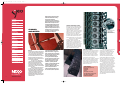
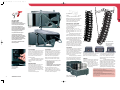
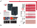
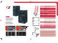
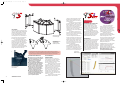
Nexo GEO NoTab.QXD
5/7/05
3:35 pm
Page 24
NEXO S.A.
154 allée des Erables
ZAC de PARIS NORD II B.P. 50107
F-95950 Roissy CDG CEDEX
France
Tél: +33 1 48 63 19 14
Fax: +33 1 48 63 24 61
eMail: [email protected]
Americas
NEXO USA, Inc
2165 Francisco Blvd. East
Suite E2
San Rafael, CA 94901-5522
USA
Tel: +1 415 482 6600
Fax: +1 415 482 6110
eMail: [email protected]
Latin America
Tel +1 305 677 9322
Fax +1 360 234 7870
Email: [email protected]
www.nexo-sa.com
LIMITED WARRANTY
NEXO loudspeakers and electronics are covered against defects in workmanship or materials for a period of two (2) years from the original date of purchase. At the option of NEXO the defective item will
be repaired/replaced with no charge for materials/labour. The item is to be adequately packaged and dispatched, pre-paid, to a NEXO authorised distributor/service centre. Unauthorised repair shall void
the warranty. The NEXO warranty does not cover cosmetics or finish and does not apply to any items which in NEXO’s opinion have failed due to used abuse, accidents, modifications or any type of misuse.
All images and text herein are the property of NEXO SA, and deemed accurate, although specifications are subject to change without notice.
v1.5
Nexo GEO NoTab.QXD
5/7/05
3:35 pm
Page 2
CONTENTS
NEXO and the Genesis of
GEO systems
Introduction to GEO S
and GEO T
GEO Tangent
Systems Technology
GEO Tangent
Systems Performance
GEO T4805 module
T 4805 Technical &
Architect Specs
GEO T2815 Module
T 2815 Technical &
Architect Specs
GEO T Connections
and Arrays
GEO & CD Rigging,
Flying & Focus
GEO S805 module
S805 Technical &
Architect Specs
GEO S830 module
S830 Technical &
Architect Specs
GEO S Rigging &
Horizontal Arrays
GEO Soft
GEO CD18 Sub-Bass
CD18 Technical &
Architect Specs
Geo CD12 Sub-Bass
CD12 Technical &
Architect Specs
NX242 Digital Controller
NX242 Technical Specs
NEXO Contact Data & www.
address, NEXO Warranty
2
www.nexo-sa.com
2
3
4
5
6
7
8
SMALLER
AND BETTER
Digital technology changed everything
about audio and the music listening
experience. Beyond obvious
improvements in system performance,
the greatest change was in expectations.
Modern audiences compare live event
sound with affordable, pristine personal
or residential playback systems and, in
doing so, add “fidelity” as a live concert
requirement. Today’s audiences expect a
CD-quality mix from a concert PA, only
on a “bigger” scale than at home, and
without significant fidelity loss.
9
10
11
12
13
14
15
16
17
18
19
20
21
22
23
24
COHERENCY, TRANSPARENCY, FIDELITY
Today, bigger sound is easy. Nearly every touring
loudspeaker system offers overwhelming power
and full-range frequency response. “Better”
however, remains elusive, and the elusive
component in “better” concert sound is coherency.
Coherency is easily achieved in controlled, directfield environment such as car stereos or MP3
earbuds. To a layman’s ears, performance
loudspeaker coherency is what happens when the
rare concert makes them feel as they do when
listening in their home or car, only much “bigger”.
More common to our shared experience
is the lack of coherency caused when
loudspeaker systems create spectrum-wide,
audible coloration (i.e. constant peaks or dips in
frequency response). These tonal imbalances
inevitably leave dissatisfied audiences as aware
of sound system performance as they are of the
on-stage performance. This is why transparent,
coherent sound reinforcement is the overriding
design criteria behind GEO S and GEO T.
Above: Infinitely precise
rigging hardware
maximizes the coherency
of GEO’s wavefront.
TIME, SPACE, FREQUENCY
NEXO S.A.
Now in its fourth decade, NEXO’s company mission is
to provide wide-ranging solutions that enhance the
science, art and commerce of sound reinforcement.
Founded by Michael Johnson, NEXO’s Managing
Director, and Chairman/R&D Director Eric Vincenot,
NEXO became a publicly traded company in May
2000. NEXO shares are listed on the Marche Libre of
the Paris Bourse (SICOVAM 4441).
The added access to capital markets
gained by this public offering strengthened NEXO’s
ability to pursue aggressively genuine audio
innovations. The first of these advanced audio
design options is the widely heralded GEO Tangent
technology, which incorporates several fundamental
wave-source patents.
NEXO’s sound reinforcement systems also
include the compact, versatile PS Series plus the
high performance Alpha System and Alphae Series. In
short, all NEXO loudspeakers, analogue and digital
controllers, power amplification, and advanced
rigging systems are designed to deliver: Sonic
Innovation That Works. NEXO is a world leader in the
design and manufacture of loudspeaker systems for
sound reinforcement.
In the 1990s the film industry used
digital audio to deliver a “bigger and
better” challenge to the comparatively
tame at-home video experience. Movie
seats were suddenly filled again,
reversing decades of declining film
revenues. Steady sales growth in home
theater systems only reinforces the
fact that people will pay for “bigger
and better”, especially when the
emphasis is on better. NEXO innovation
has taken this trend to its logical
conclusion. With GEO, we offer sound
reinforcement systems that are
smaller and better. We think of it as a
win-win solution, without compromise.
Coherency applies to sound system transparency
in the three-dimensional context of Time, Space
and Frequency. At issue are Comb Filters, the
audible, undesirable sound system artifacts
caused by closely-spaced peaks and notches in
the frequency domain, and multiple arrivals in
the time domain with very short time
differentials and similar amplitudes. As multiple
arrivals become widely separated in time (and
space), coherency is lost. Meanwhile frequency
response displays wide peaks and dips which
change depending on spatial positioning of the
listener and sound sources.
TOTAL COHERENCY
GEO S Array (as rigged at left)
8X GEO S805
1X GEO S830
2X CD12
Total Length: 2.15m (7.05ft)
Total Width: 600mm (1.96ft) (at front)
Total Weight: 193kg(414.6lbs)
NOTHING ELSE COMPARES
Most naturally occurring sound sources
however, such as unamplified singers or
instrumentalists, never present listeners with
multiple arrivals (i.e. comb filters). As such,
human hearing never evolved to interpret
amplified sounds, and our ear-to-brain
connections never adapted to the relatively
modern comb filter. Moreover, even when comb
filters seem comparatively “fine” and not clearly
audible, they continue to make it difficult to
“hear what is going on.” This is especially true
for HF percussive sounds or vocal consonants.
No electronics will fix this situation. A
whole-system EQ curve can never really “flatten”
these peaks and dips. At some locations and
certain frequencies, equalization will actually
make things worse. At others, presumably FOH, it
might make them better. Only true system
coherency will allow engineers to execute
effective tonal adjustments that will work at
every seat and for every pair of ears. This is why,
at NEXO, our pursuit of coherency drove the three
years of R&D that delivered GEO. We’re extremely
proud of the results.
3
Nexo GEO NoTab.QXD
5/7/05
3:36 pm
Page 4
GEO SCIENCE
& SOLUTIONS
GEO HRW (reflective) Wavesources are:
■ Very accurate
Photo1: GEO S Wavesource
with Configurable Directivity
Device flanges.
■ Extremely compact
■ Capable of Perfect Array Coupling
Through combining Wavefronts
■ Exceptionally versatile
Fig 2: Coherency through
GEO Wave Propogration.
Tangent wavefronts
radiate from common
virtual array source.
the woofer up to at least 1200Hz.
In practice, we can’t expect to centre 8inch woofers closer than 10 inches, otherwise
they will be a full wavelength apart at 1300Hz
and adjacent woofers will start to become
separate sources at 325Hz (1/4 wavelength
spacing) and will begin to develop individual
lobes at 625Hz. This frequency is far too low to
cross over into the compression driver.
The solution was GEO’s Directivity/
Phase Device (DPD) (see Photo 3) on each cone,
which causes 8-inch woofers to behave like twin
4-inch drivers with two acoustical centres
spaced 5 inches. The DPD extends the upper
frequency limit for line source coupling between
adjacent woofers. As such, GEO system’s 8-inch
MEASUREMENT CONFIRMED
To realise coherency, our most pressing design
challenge was development of a sound system
that allowed a multiple full-range cabinets to
behave as if they share a single sound source.
Obviously, this required acoustic coupling
between multiple cabinets, but GEO Technology
goes far beyond traditional line arrays. In fact,
had we not been able to achieve coherency
beyond the mid-to-HF coupling inherent in nearly
every existing line array, NEXO would never have
entered the vertical array marketplace.
The point is that a Brüel and Kjaer
Acoustic Analysis system doesn’t care what
system you place in front of its calibration
microphone. Nor does advanced MATLAB
software care what data you feed it. So, when
these advanced measurement tools confirmed
that GEO S and GEO T loudspeaker systems
displayed superior sonic performance that
exceeded even our rigorous standards, it was
clear that GEO’s unique wavesource had
redefined control of acoustic energy. Simply put,
GEO’s hyperboloid acoustic reflector eliminates
destructive interference, with the most coherent
output of any loudspeaker, anywhere.
4
Fig 1: Computer
Rendered, GEO S805
Wavesource
enclosure. It also provides a virtual source that is
behind the rear of the enclosure. As such, GEO
wavesource measurements display a high degree
of correspondence between mathematical
predictions and real world results.
One other GEO innovation that must be
mentioned is the Configurable Directivity Device
flanges (CDD). (see Photo 1) An unprecedented
NEXO development that is easy to use once you
know how and when, these devices allow system
designers, especially those working on
permanent installations, to precisely alter
wavesource behaviour.
GEO S Series loudspeakers ship with
the flanges (120° dispersion in the noncoupling plane). In curved vertical arrays, CDD
flanges can be used on the bottom two rows of
curved vertical arrays, to fill in coverage gaps in
the front rows or; on all rows of curved vertical
arrays, in cases where 120° of horizontal
coverage is preferred to 80°. In horizontal arrays
of GEO S830s, the Configurable Directivity
Device can be used to widen the array’s vertical
coverage of from 80° to 120°.
HOW IT WORKS
BIG PICTURE
Fig 2 (below left): HRW
creates a virtual acoustic
wavesource that is
“outside” the loudspeaker
cabinet.
Photo 3: GEO S Directivity Phase Device
THE GEO HYPERBOLOID REFLECTIVE
WAVESOURCE™
Hyperboloid Reflective Wavesource (HRW™)
technology produces precise and predictable
results so that GEO wavesources couple
optimally without destructive interference. This
is why the GEO rigging system is designed to
control angular splay to 0.01° precision.
The key to GEO’s success however is in
the innovative method that the HRW uses to
control acoustic energy so that users can craft
high-output wavefronts to precisely fit audience
areas, more coherently and more evenly, than
previously possible.
The HRW wavesource (see Figure 1 &
Photo 1) controls acoustic energy with an
acoustical reflector (i.e. mathematically
calculated hyperboloid acoustic mirror, derived
from a rigorous set of geometrical
transformations). Thus the HRW creates a virtual
acoustic wavesource that is “outside” the
loudspeaker cabinet (see Figure 2).
This patent-pending technique allows
the designer to locate the real source (the
compression driver) almost anywhere inside the
As mentioned, GEO devices can use a HRW to
position a virtual sound source “behind” the
physical enclosure (see Figure 2). Notice that the
path lengths from the virtual and real sources,
to the horn mouths, are identical at the coupling
points.
This is the critical concept. Where the
two wavefronts touch they will therefore be in
phase because the pressure wave takes the
same amount of time to travel an identical path
length to the coupling point, regardless of where
its real source is located in relation to that
coupling point.
This was difficult to achieve and not the
only technical challenge involved. Several other
design obstacles also had to be overcome. For
example, GEO S uses 8-inch cone woofers and 1
inch compression drivers, so we need to operate
Photo 4: GEO T Directivity Phase Device
cone driver loses neither power handling, nor LF
extension. In the GEO S Series, the DPD takes
the form of a phase plug that is attached to the
frame of the cone transducer. In the GEO T
Series, the DPD is part of the molding that also
includes the Configurable Directivity Device (see
Photo 4).
Also, because GEO T uses two 8-inch
cone woofers and 1-inch compression drivers, the
GEOT woofer must operate up to at least 1200Hz.
As such, GEO T’s LF coupling performs in nearly
identical fashion to non-cardioid arrays, in that
our smaller arrays have proportionally more bass
than large ones, because the LF interfering
effects are much smaller.
A GEO Tangent Array is not a “line array” GEO
Technology is equally effective in designing and
deploying tangent horizontal arrays or curved
vertical arrays. For best results in a specific
application most users need to know how multispeaker arrays interact with audience geometry,
along with the benefits and drawbacks of curved
vertical arrays and horizontal arrays.
The cardioid works in the vertical as
well as the horizontal plane and it is therefore
pretty obvious that the effect will be much more
impressive in a small array. As the array becomes
larger/longer (and most often flatter as a
consequence of its length) the HF couples very
effectively and becomes more prominent than the
LF, while LF increases nearly proportionally to the
quantity of cabinets, without the need for
extensive LF equalisation.
THE SUB-BASS SOLUTION
While bringing coherency and cardioid
performance to LF was a challenge, cardioid or
hypercardioid control of extreme LF or sub-bass
was the capstone of GEO system design. To
achieve this we looked toward input transducer
(i.e. microphone) design.
Microphones have long offered cardioid
polar patterns. As such, cardioid loudspeakers
can be simply described as a “cardioid mic in
reverse”. NEXO’s approach uses the interference
between two arrivals of the same amplitude in
order to create off-axis rejection with rear
reduction as high as -15dB. We apply the
interference between two sources of identical
amplitude to radiate a cardioid polar pattern with
off-axis attenuation (see Fig 3).
To achieve this, NEXO R&D designed
advanced electronic control algorithms to allow
NX242 TDcontrollers to maximise SubBass
pattern control for CD12 and CD18 cabinets. For
more information regarding sub-bass control
please see pg 20. For more information on NX242
please see pg 22.
Fig 3: Cardoid sub-bass coverage from CD SubBass
5
Nexo GEO NoTab.QXD
5/7/05
3:36 pm
Page 6
■ GEO T4805
■ GEO T2815
GEO T4805
A compact, extremely high-output array
module, the T4805 is the centerpiece to GEO T
vertical tangent array system design. The 5°
Hyperboloid Reflective Wavesource is
optimized so that multiple GEO loudspeakers
coherently radiate tangent wavefronts,
allowing these curved vertical arrays to
deliver consistent front-to-rear SPL across
all coverage areas. Advanced DSP
algorithms, applied by the NX242
TDcontroller, provide GEO T systems with
unrivalled midbass directional control.
903 mm
[35.55"]
750 mm
[29.53"]
GEO T4805 rear view
SHIPPING & ORDERING
Packaging
COUPLING PLANE COVERAGE (°)
NON-COUPLING PLANE COVERAGE (°)
120
120
60
60
0
0
60
60
120
120
100Hz
1kHz
10kHz
<-24dB
-24 /-18 dB
-18 /-12 dB
-12 /-6 dB
-6 / -3 dB
-3 / 0 dB
100Hz
1kHz
10kHz
GEO T4805 Off-Axis Response
6 GEO T4805 @ 5° Off-Axis Response
IMPEDANCE (Ohm)
ON-AXIS RESPONSE (dB)
256
10
128
0
64
32
10
16
20
8
4
30
100Hz
1kHz
6 GEO T4805 @ 5° On-Axis Response 75 Hz XOver
6
www.nexo-sa.com
GEO T4805 PRODUCT FEATURES
Components
HF: 1 x 3" voice coil, 1.4” throat neodymium 16Ω driver on a Hyperboloid Reflective
Wavesource.
LF front section: 2 x 8” (20cm) neodymium hi-flux 16Ω drivers in series.
LF back section: 2 x 8” (20cm) neodymium hi-flux 16Ω drivers in series.
Height x Width x Depth
Enclosure: 250 x 750 x 627mm (9 7/8” x 29 9/16” x 24 11/16”)
Array Module: 286 x 903 x 627mm (11 1/4” x 35 1/2” x 24 11/16”)
Shape
5° Trapezoid.
Weight
52kg(114.6lbs) net, including flying system.
Connectors
1x AMPHENOL 6-pole EP6 socket In, 1 x AMPHENOL AP6 6 pole cable + connector Through.
Construction
Baltic birch ply finish with structured black coating for the main structure.
Metal box for the rear section with dark grey coating.
Front Finish
Injected polyurethane flange with metallic grey coating.
Flying Points
Integral flying system. Intercabinet angle adjustments = 0.125° to 5° (logarithmic steps).
SYSTEM SPECIFICATIONS GEO T4805 with NX242 TDcontroller
Frequency Response [a]
67Hz – 19kHz ± 3dB
Usable Range @-6dB [a]
60Hz – 20kHz
Sensitivity 1W @ 1m [b]
109dB SPL nominal – 107dB SPL wideband
Peak SPL @ 1m [b]
Configuration dependent [d].
Dispersion [c]
Coupling plane: not usable alone. Configuration dependent [d]. Non-coupling plane: 90°.
Crossover Frequencies
250Hz & 1.3kHz active
Nominal Impedance
LF rear: 32Ω - MF/LF front: 32Ω - HF: 16Ω
Recommended Amplifiers HF: 3000Watts into ~3Ω/6 cabinets.
MF/LF (front section): 6000Watts bridged mono into ~6Ω/6 cabinets.
LF (rear section): 6000Watts bridged mono into ~6Ω/6 cabinets.
SYSTEM OPERATION
Electronic Controller
The NX242 Digital TDcontroller presets are precisely matched to the GEO T Series cabinets
and include sophisticated protection systems. Using GEO T Series cabinets without
properly-connected NX242 Digital TDcontroller will result in poor sound quality and can
damage components.
Dispersion Configuration
The CDD is configured for 90° dispersion in the non-coupling plane.
Array Design
Via GEOSoft compiled Matlab application or EASE/CATT .dII (latest version available at
www.nexo-sa.com).
Subbass
CD18 Supercardiod SubBass (requires two NX242 outputs and two amplifier channels).
Speaker Cables
LF rear: 1(-)/2(+) - LF/MF front: 3(-)/4(+) - HF: 5(-)/6(+).
Rigging System
Please refer to the GEO user manual before any operation.
10kHz
100Hz
1kHz
GEO T4805 Impedance LF Rear & LFMF Front (Black), HF (Grey)
10kHz
627 mm
[24.68"]
Shipping Weight & Volume
T4805s are packaged individually or in groups of three in NEXO GEO T flight case.
Order as GEO T4805 (includes 4x BLGEOT12-30 quick release pins).
1x T4805 = 53.5kg(117.9 lbs), 0.15 cu m (5.3 cu ft)
As part of a policy of continual improvement, NEXO reserves the right to change specifications without notice. [a] Response curves and
data: anechoic far field above 300Hz, half-space below 300Hz. [b] Sensitivity & peak SPL: will depend on spectral distribution. Measured
with band limited pink noise. Refers to the specified ±3dB range. Data are for speaker + processor + recommended amplifier
combinations. [c] Directivity curves and data: 1/3 octave smoothed frequency response, normalized to on-axis response. Data obtained
by computer processing of offaxis response curves. [d]Please refer to the GEO T User Manual. Usable range data: frequency response
capability with TD crossover slopes removed.
286 mm
[11.26"]
250 mm
[9.84"]
ARCHITECT’S AND ENGINEERING SPECIFICATIONS
The 3-way full range tangent array module shall have four 8", 16Ω long-excursion neodymium hi-flux cone transducers
wired in series (two front-firing, two rear-firing), two 8", 16Ω long excursion neodymium hi-flux midrange cone drivers
wired in series (four 8" drivers total) and a 1.4", 16Ω neodymium compression driver on a hyperboloid reflective
wavesource. The system's coverage shall be configuration-dependent in the coupling plane. In the non-coupling plane it
shall be 90°. The system's Directivity Index shall be configuration-dependent. Nominal Sensitivity shall be 109dB (107dB
wideband). When driven by a NEXO NX242 Digital TDcontroller properly connected to amplification capable of delivering
6000 Watts into a 6Ω (nominal) load (6 cabinets per amplifier channel in parallel). The system shall be capable of
138dB peak SPL (for a single enclosure: configuration-dependent when arrayed), with a frequency response of 67Hz to
19kHz ±3dB (60Hz to 20Hz ±6dB). The system shall include an active and passive crossover with DSP algorithms for
directional control of midbass. Electrical connections shall be made via one 6-pole AMPHENOL EP6 socket and one 6pole AMPHENOL EP6 plug.
The system shall weigh 52kg(114.6lbs) and have a tuned, ported 5° trapezoidal enclosure constructed of 18ply Baltic
birch (midsection), aluminum (rear driver compartment), finished in structured black coating and having exterior
dimensions no greater than 286mmH x 903mmW x 607mmD (111/4"x 35.5" x 24 5/8"). Exterior hardware shall include
an integral array assembly system with logarithmic steps and 0.01° precision. Interior components shall be protected by
an injection-molded polyurethane Configurable Directivity Device flange. The system shall be the NEXO GEO T4805 with a
NEXO NX242 Digital TDcontroller. Other integrated loudspeaker/controller systems shall be acceptable, provided
independent laboratory test results verify these specifications are equalled or exceeded.
7
Nexo GEO NoTab.QXD
5/7/05
3:36 pm
Page 8
■ GEO T4805
■ GEO T2815
GEO T2815
A compact, extremely high-output array
module, the versatile T2815 is often used at
the bottom of T4805 vertical tangent arrays
(see pg #9), and in traditional horizontal
arrays. The 15° Hyperboloid Reflective
Wavesource is optimized so that multiple
T2815s coherently radiate tangent
wavefronts, when used in curved vertical
arrays, to deliver consistent front-to-rear
SPL across all coverage areas. Twin rearfiring passive resistors provide exceptional,
passive midbass directional control.
903mm
[35.55"]
750mm
[29.53"]
GEO T2815 rear view
COUPLING PLANE COVERAGE (°)
NON-COUPLING PLANE COVERAGE (°)
120
120
60
60
0
0
60
60
120
120
100Hz
1kHz
10kHz
<-24dB
-24 /-18 dB
-18 /-12 dB
-12 /-6 dB
-6 / -3 dB
-3 / 0 dB
100Hz
1kHz
10kHz
GEO T2815 Off-Axis Response
6 GEO T2815 @ 15° Off-Axis Response
IMPEDANCE (Ohm)
ON-AXIS RESPONSE (dB)
256
10
128
0
64
32
10
16
20
8
4
30
100Hz
1kHz
6 GEO T2815 @ 15° On-Axis Response 75 Hz XOver
8
www.nexo-sa.com
10kHz
100Hz
1kHz
GEO T2815 Impedance LF/MF (Black), HF (Grey)
10kHz
537mm
[21.14"]
GEO T2815 PRODUCT FEATURES
Components
HF: 1 x 3” voice coil, 1.4” throat neodymium 16Ω driver on a hyperboloid
reflective wavesource.
MF/LF (front-firing): 2x 8” (20cm) neodymium hi-flux 16Ω drivers in series.
LF (rear-firing). 2x passive acoustic resistors
Height x Width x Depth
249 x 903 x 537mm (9 13/16” x 35 1/2” x 21 1/8”) including array assembly system
Shape
15° Trapezoid
Weight
29kg (63.9 lbs) net, including array assembly system
Connectors
1x AMPHENOL 6-pole EP6 socket In; 1x AMPHENOL AP6 6-pole connector Through.
Construction
Baltic birch ply finish with structured black coating for the main structure.
Metal box for the rear section, with dark grey coating.
Front Finish
Injected polyurethane flange, with metallic grey coating.
Flying Points
Integral flying system. Intercabinet angle adjustments = 0.125° to 5°
(logarithmic steps).
SYSTEM SPECIFICATIONS GEO T2815 with NX242 TDcontroller
Frequency response [a]
85Hz – 19Hz ±3dB
Usable range @-6dB [a] 77Hz – 20kHz
Sensitivity 1W @ 1m [b] 107dB SPL nominal (105dB SPL wideband)
Peak SPL @ 1m [b]
Configuration dependent (d)
Dispersion [c]
Vertical plane. Configuration dependent [d]. 120°Low Frequency: Cardioid
Crossover frequency
MF/LF – HF (front): 1.3kHz active.
Nominal impedance
HF: 16Ω; MF/LF front: 32Ω.
Recommended amplifiers HF: 3000Watts into ~3Ω (6 cabinets parallel per amp channel).
MF/LF front section: 6000Watts into ~6Ω (6 cabinets parallel per bridged mono amp).
SYSTEM OPERATION
Electronic Controller
The NX242 Digital TDcontroller presets are precisely matched to the GEO T Series cabinets
and include sophisticated protection systems. Using GEO T Series cabinets without
properly-connected NX242 Digital TDcontroller will result in poor sound quality
and can damage components.
Dispersion Configuration
The CDD is configured for 120° in the non-coupling plane.
Array Design
Via GEOSoft compiled Matlab application or EASE/CATT .dII (latest version available at
www.nexo-sa.com).
Subbass
CD18 Supercardiod SubBass (requires 2x NX242 outputs and two amplifier channels).
Speaker Cables
1(-)/2(+) NC - LF/MF front: 3(-)/4(+) - HF: 5(-)/6(+).
Rigging System
Please refer to the GEO user manual before any operation.
SHIPPING & ORDERING
Packaging
T2815s are packaged individually or in groups of three in NEXO GEO T flight case.
Order as GEO T2815 (includes 4x BLGEOT12-30 quick release pins).
Shipping Weight & Volume 1x T2815 = 30.5kg(67.2lbs), 0.15 cu m (5.3 cu ft)
As part of a policy of continual improvement, NEXO reserves the right to change specifications without notice. [a] Response curves and
data: anechoic far field above 300Hz, half-space below 300Hz. [b] Sensitivity & peak SPL: will depend on spectral distribution. Measured
with band limited pink noise. Refers to the specified ±3dB range. Data are for speaker + processor + recommended amplifier
combinations. [c] Directivity curves and data: 1/3 octave smoothed frequency response, normalized to on-axis response. Data obtained
by computer processing of offaxis response curves. [d]Please refer to the GEO T User Manual. Usable range data: frequency response
capability with TD crossover slopes removed.
249mm
[9.80"]
213mm
[8.39"]
ARCHITECT’S AND ENGINEERING SPECIFICATIONS
The 2-way full range tangent array module shall have two 8" long-excursion neodymium hi-flux cone transducers wired
in series and a 1.4", 16Ω neodymium compression driver on a hyperboloid reflective wavesource. The system's coverage
shall be configuration-dependent in the coupling plane. In the non-coupling plane it shall be 120°. Nominal Sensitivity
shall be 107dB (105dB wideband). When driven by a NEXO NX242 Digital TDcontroller properly connected to
amplification capable of delivering 6000Watts into a 3Ω (nominal) load (6 cabinets per amplifier channel in parallel).
The system shall be capable of 138dB peak SPL (for a single enclosure: configuration-dependent when arrayed), with a
frequency response of 85Hz to 19kHz ±3dB (77Hz to 20kHz ±6dB). The system shall include an active and passive
crossover, although directional control of midbass coverage is passive. Electrical connections shall be made via one 6pole AMPHENOL EP6 socket and one 6-pole AMPHENOL EP6 plug.
The system shall weigh 29kg(63.9lbs) and have a tuned, ported 15° trapezoidal enclosure constructed of 18ply Baltic
birch (midsection), aluminum (rear driver compartment), finished in structured black coating and having exterior
dimensions no greater than 249mmH x 903mmW x 537mmD (9 13/16" x 35.5" x 21 1/8"). Exterior hardware shall include
an integral array assembly system with logarithmic steps and 0.01° precision. Interior components shall be protected by
an injection-molded polyurethane Configurable Directivity Device flange. The system shall be the NEXO GEO T2815 with a
NEXO NX242 Digital TDcontroller. Other integrated loudspeaker/controller systems shall be acceptable, provided
independent laboratory test results verify these specifications are equalled or exceeded.
9
Nexo GEO NoTab.QXD
5/7/05
3:36 pm
Page 10
Fig 3: BLGEOT12-30
Six BLGEOT12-30 locking pins (see Figure #1)
are provided with the GEO T4805 and four
BLGEOT12-30 locking pins are provided with the
GEO T2815. All holes on GEO T side rigging
plates are 12mm diameter, and match the
12mm diameter x 30mm length pins.
GEO T SERIES ARRAY
ASSEMBLY SYSTEM
No portable loudspeaker system,
intended for the ups and downs of touring
sound, is really road-worthy without a
quick and user-friendly flying and
transport system. We believe our GEO T
Series Array Assembly System (TSAAS) to
be the most elegant and quite likely the
fastest rigging system available.
PRECISION FOCUS - HOW IT WORKS
Because GEO T arrays require very high
accuracy, angle sequences follow a logarithmic
scale. Angle setting values are:
Bumper to GEO T4805: 0°
GEO T4805 to GEO T4805: 0.125° - 0.20° 0.315° - 0.50° - 0.80° - 1.25° - 2.0° - 3.15° - 5.0°
GEO T4805 to GEO T2815: 6.30° - 8.00° - 10.0°
GEO T2815 to GEO T2815: 6.30° - 8.00° - 10.0° 12.5° - 15°
TSASS deploys in either Tension mode or
Compression mode (see Figure 4). In Tension
Mode, angles between cabinets are set by the force
of gravity applied from top to bottom of the array.
When the array is lifted into position, each module
will fall automatically into the proper angle.
In Compression Mode, angles between
cabinets are set by a pull-back force applied from
bottom to top of the array. When the array is lifted
into position, all cabinets are at 0°, and when the
pull-up force is applied, each module is lifted
from the rear into the proper angle(see Figure 5).
GEO T4805 ships
with TSASS Rigging
Hardware
Our system enables various system
configurations to be flown with a
minimum quantity of motor hoists. Most
importantly, the TSASS’s custom-designed
permits easy deployment while being
functionally optimised to match precisely
the mechanical and acoustical
characteristics of GEO T2815 and GEO
T4805 Array Modules.
GEO T2815 ships
with TSASS Rigging
Hardware
Fig 4: Tension mode
Fig 5: Compression mode
Photo 3 (below): GeoSight
Inclinometer System.
(cabling not shown)
CD18 RIGGING
VERTICAL ARRAYS
FLYING VERTICAL
Vertical and horizontal arrays are unique in their
behaviour and intended applications. Vertical
GEO arrays are intended for applications where
the horizontal coverage (GEO S 80º or 120º, or
GEO T 90º) is suitable and even SPL from the
first row to the last row of the audience is
desired (everywhere).
Properly deployed, GEO Series systems
can provide extremely even SPL throughout the
depth of your audience, including balcony
coverage.
The GEO T Series Array Assembly System requires
three experienced persons for set-up: typically
one motor hoist operator, and one GEO T operator
per side of the cluster. When properly used and
maintained, TSASS will provide many years of
reliable service. Vertical angle adjustment
between cabinets has been limited to specific
settings to ensure coherent acoustic coupling.
HORIZONTAL ARRAYS
Photo 1 (above):
Connecting two GEO
T4805s with integral
cabling and Amphenol
EP6 connector
10
www.nexo-sa.com
Horizontal arrays deliver equal power to equal
angles, with SPL decreasing as distance
increases. Horizontal arrays of GEO S830 and
GEOT 2815 cabinets provide exceptional control
of horizontal coverage but are not intended to
provide the same even SPL capability as a GEO
tangent vertical array.
For more information see pg #16.
Compared to the precise aiming required by GEO
T arrays, CD18 SubBass rigging is relatively
simple. Each CD18 is designed to stack directly
on top of and/or below another CD18. The
vertical stacks are required to realize maximum
LF performance, and of course, there is a front
and rear to each CD cabinet.
Although flying rigging is available for
CD 18s, they are most frequently stage/ground
stacked. To maximize CD18, or CD12 groundstacked cardioid characteristics, a free (open)
There are 5 main parts to the Geo T flying system:
1. The main flying bumper
2. The main kelping beam
3. The GEO T cabinets
4. The kelping plate or lower pull up assembly
5. The kelping chain and clutch assembly
Each GEO T Array Module includes an
individual rigging system, which is factorymounted by NEXO. GEO T Series Tangent Array
Modules are transported pre-pinned in a flight
case of three cabinets (see photo 2).
Photo 2 (above): GEO T4805s
packed in castered flightcase
space is needed directly behind the SubBass
stack. Therefore, whenever possible, users should
avoid placing the devices against any rear
barriers such as back walls or staging barriers.
TRANSPORT
As mentioned, the GEO T Series cabinets travel
conveniently, in groups of three, when packed
in NEXO-provided castered flight cases.
Although relatively compact, the
CD18 is too large for individual
flight cases, and as such requires
its own castered wheelboard for
easily handling.
GEOSIGHT INCLINOMETER
As a high-performance, optics-derived system,
successful GEO T deployment requires precise
focus (i.e. aiming). Experienced users often
apply laser-aiming procedures once their GEO T
system is airborne.
The NEXO GeoSight Inclinometer
System was specifically designed for installation
of NEXO Geo Tangent Array Series systems. While
not the only method of achieving a coherent
wavefront, proper GeoSight use enables accurate
GEO T array installation in minimum time. Visit
our website at www.nexo-sa.com, or contact
your NEXO agent, for more GEOSight information.
This brochure text is not intended as a rigging user manual, but rather to provide the
general system details used in GEO T system rigging.
The GEO T Array Assembly System is a professional precision tool and should be handled
with extreme care. Only persons who are fully conversant with the operation
of the GEO T Series Array Assembly System and provided with suitable safety equipment
should install and operate the system.
Misuse of the GEO T Series Array Assembly System could lead to dangerous
consequences. Also there are several potential dangers: we won’t list all of them here.
We will mention possibly the most important operational warning: never put your fingers
into the side rigging plates!
11
Nexo GEO NoTab.QXD
5/7/05
3:36 pm
Page 12
S805 Rear view
■ GEO S805
■ GEO S830
428 mm
GEO S805
S805 Front view with grill
COUPLING PLANE COVERAGE (°)
NON-COUPLING PLANE COVERAGE (°)
120
60
60
0
0
60
60
120
120
1kHz
10kHz
100Hz
6 GEO S805 @ 5° Off-Axis Response
10
1kHz
IMPEDANCE (Ohm)
256
128
0
64
32
10
16
20
8
4
30
100Hz
1kHz
10kHz
6 GEO S805 @ 5° On-Axis Response Wideband (Dark), Ground (light), Flown (Black)
12
www.nexo-sa.com
100Hz
GEO S805 Impedance
1kHz
S805s are packaged in pairs.
2x S805s: 29.2kg (64.2 lbs) 0.135 cu m (4.8 cu ft)
As part of a policy of continual improvement, NEXO reserves the right to change specifications without notice. [a] Response Curves and
Data: Anechoic Far Field above 300Hz, Half-space below 300Hz. Usable Range Data: Frequency Response Capability with TD crossover
slopes removed. [b] Sensitivity & Peak SPL: will depend on spectral distribution. Measured with band limited Pink Noise. Refers to the
specified +/- 3dB range. Data are for Speaker + Processor + recommended amplifier combinations. [c] Directivity Curves and Data: 1/3
octave smoothed frequency response, normalized to On-Axis response. Data obtained by computer processing of off-axis response
curves. [d] Please refer to the GEO User Manual.
10kHz
GEO S805, 80° CDD Configuration Off-Axis Response
ON-AXIS RESPONSE (dB)
SHIPPING &ORDERING
Packaging
Shipping Weight & Volume
<-24dB
-24 /-18 dB
-18 /-12 dB
-12 /-6 dB
-6 / -3 dB
-3 / 0 dB
5°
120
100Hz
302 mm
276 mm
The GEO S805 is compact, high-output array module
designed for use in vertical tangent arrays. The Hyperboloid
Reflective Wavesource allows multiple GEO S8 loudspeakers
to radiate tangent wavefronts with coherent output.
The 5° wavesource is optimized for the construction of
curved vertical arrays that deliver equal power to equal
coverage areas for consistent SPL from front to rear of the
audience area.
Advanced DSP algorithms, applied by the NX242 TDcontroller,
precisely integrate GEO S systems with CD12 SubBass
cabinets, so they may be flown together, without causing any
interference between the GEO S and CD12 wavefronts.
GEO S805 PRODUCT FEATURES
Components
LF 1x 8” (20cm) Neodymium Hi-flux 16Ω Driver
HF: 1x 1” Throat Neodymium Driver on a Hyperboloid Reflective Wavesource
Height x Width x Depth
428 x 276 x 303mm (16 7/8" x 10 7/8" x 11 7/8")
Shape
5° Trapezoid
Weight
13kg (28.6lbs) net
Connectors
2x NL4MP 4-pole SPEAKON (In & Through)
Construction
Baltic Birch Ply finish with structured black coating.
Dark grey carpet is optional.
Fittings
Grill Perforated Steel
Flying
Integral flying system. Intercabinet Angle Adjustments = .31° to 5° (logarithmic steps).
SYSTEM SPECIFICATIONS GEO S805 with NX242 TDcontroller
Frequency Response [a]
67Hz – 19kHz ± 3dB
Usable Range @-6dB [a]
60Hz – 20kHz
Sensitivity 1W @ 1m [b]
99dB SPL Nominal -97dB SPL Wideband
Peak SPL @ 1m [b]
Configuration dependent [d].
Dispersion [c]
Coupling Plane: Not usable as a single cabinet. Configuration dependent [d].
Non-Coupling Plane
120° (configurable to 80°).
Crossover Frequency
1.6kHz Passive
Nominal Impedance
16Ω
Recommended Amplifiers 1500 to 3000Watts into 4Ω / 4x cabinets per channel. Up to 6x cabinets per channel
may be connected to large amplifiers capable of operating into low impedance loads.
SYSTEM OPERATION
Electronic Controller
The NX242 Digital TDcontroller presets are precisely matched to the GEO S8 Series
cabinets and include sophisticated protection systems. Using GEO S8 Series cabinets
without a properly-connected NX242 Digital TDcontroller will result in poor sound quality
and can damage components. The GEO S805 & S830 can be used without the optional
CD12 Hypercardiod Sub. In this case the NX242 can be used in stereo. With the CD12
Hypercardioid Sub, each Sub channel requires two NX242 outputs and the NX242 will
operate in mono.
HF Dispersion Configuration After release of the front grill from its fittings, the HF Waveguide can be configured
for 80° or 120° dispersion in the non-coupling plane.
Array Design
S805 and S830 cabinets, having tangent waveguides, can be mixed in the same array.
Minimum configuration or Vertical Tangent Arrays is 5x S805 & 1x S830 (4x S805 for
paging applications only). CD12s are optional. A a ratio of 1x CD12 per 3x full-range GEO
modules is required for proper subbass output.
Speaker Cables
The GEO S805 and S830 are wired 1- & 1+ on both Speakon connectors, 2- & 2+ are not
connected.
Rigging System
Please refer to the GEO User Manual before any operation.
10kHz
ARCHITECT’S AND ENGINEERING SPECIFICATIONS
The 2-way full-range tangent array module shall have one 8" long-excursion neodymium hi-flux cone transducer and a
1" neodymium compression driver on a hyperboloid reflective wavesource. The system’s coverage shall be configurationdependent in the coupling plane. In the non-coupling plane it shall be 80°, configurable to 120° with user-removable
flanges. The system’s Directivity Index shall be configuration-dependent. Nominal Sensitivity shall be 99dB (97dB
wideband). When driven by a NEXO NX242 Digital TDcontroller properly connected to amplification capable of delivering
1500 to 3000Watts into a 4Ω (nominal) load (4x cabinets per amplifier channel in parallel), the system shall be capable
of 125dB to 128dB peak SPL (for a single enclosure: configuration-dependent when arrayed), with a frequency response
of 67Hz to 19kHz ±3dB (60Hz to 20kHz ±6dB). The system shall include an internal passive crossover. Electrical
connections shall be made via two 4-pole NL4MP SPEAKON connectors. The system shall have a tuned, ported 5°
trapezoidal enclosure constructed of 18ply Baltic birch, finished in structured black coating. With flying hardware the
system shall weigh 13kg(28.6lbs) and have exterior dimensions no greater than 428mmH x 276mmW x 302mmD (16 7/8"
x 10 7/8" x 11 7/8"). Exterior hardware shall include an integral array assembly system with logarithmic steps and 0.01°
precision. Interior components shall be protected by a powder-coated perforated steel grille. The system shall be the
NEXO GEO S805 with a NEXO NX242 Digital TDcontroller. Other integrated loudspeaker/controller systems shall be
acceptable, provided independent laboratory test results verify these specifications are equalled or exceeded.
13
Nexo GEO NoTab.QXD
5/7/05
3:36 pm
Page 14
S830 Rear view
■ GEO S805
■ GEO S830
GEO S830
428 mm
SYSTEM OPERATION
Electronic Controller
GEO S Series loudspeakers ship with 120°
dispersion (in the non-coupling plane)
Configurable Directivity Devices (CDD), but are
field-changeable to 80° CDDs. To maximize downfill coverage, CDFs are used on GEO S830s for the
bottom two rows of curved vertical arrays.
NON-COUPLING PLANE COVERAGE (°)
120
60
60
0
0
60
60
120
120
10kHz
<-24dB
-24 /-18 dB
-18 /-12 dB
-12 /-6 dB
-6 / -3 dB
-3 / 0 dB
30°
120
100Hz
1kHz
IMPEDANCE (Ohm)
ON-AXIS RESPONSE (dB)
256
128
0
64
32
10
16
20
8
4
30
100Hz
1kHz
10kHz
3 GEO S830 @ 30° On-Axis Response Wideband (Dark), Ground (light), Flown (Black)
14
www.nexo-sa.com
100Hz
GEO S830 Impedance
1kHz
As part of a policy of continual improvement, NEXO reserves the right to change specifications without notice. [a] Response Curves and
Data: Anechoic Far Field above 300Hz, Half-space below 300Hz. Usable Range Data: Frequency Response Capability with TD crossover
slopes removed. [b] Sensitivity & Peak SPL: will depend on spectral distribution. Measured with band limited Pink Noise. Refers to the
specified +/- 3dB range. Data are for Speaker + Processor + recommended amplifier combinations. [c] Directivity Curves and Data: 1/3
octave smoothed frequency response, normalized to On-Axis response. Data obtained by computer processing of off-axis response
curves. [d] Please refer to the GEO User Manual.
10kHz
GEO S830, 120° CDD Configuration Off-Axis Response
3 GEO S830 @ 30° Off-Axis Response
10
302 mm
S830 Front view with grill
COUPLING PLANE COVERAGE (°)
1kHz
The NX242 Digital TDcontroller presets are precisely matched to the GEO S8 Series
cabinets and include sophisticated protection systems. Using GEO S8 Series cabinets
without a properly-connected NX242 Digital TDcontroller will result in poor sound quality
and can damage components. The GEO S805 & S830 can be used without the optional
CD12 Hypercardioid Sub. In this case the NX242 can be used in stereo. With the CD12
Hypercardiod Sub, each Sub channel requires two NX242 outputs and the NX242 will
operate in mono.
HF Dispersion Configuration After release of the front grill from its fittings, the HF Waveguide can be configured
for 80° or 120° dispersion in the non-coupling plane.
Array Design
S805 and S830 cabinets, having tangent waveguides, can be mixed in the same array.
Minimum configuration for Vertical Tangent Arrays is 5x S805 & 1x S830 (4x S805 for
paging applications only). CD12s are optional. A a ratio of 1x CD12 per 3x full-range GEO
modules is required for proper subbass output.
Speaker Cables
The GEO S805 and S830 are wired 1- & 1+ on both Speakon connectors, 2- & 2+ are not
connected.
Rigging System
Please refer to the GEO User Manual before any operation.
SHIPPING &ORDERING
Packaging
S830s are packaged in pairs.
Shipping Weight & Volume 2x S830s: 29.2kg (64.2 lbs) 0.135 cu m (4.8 cu ft)
276 mm
The compact GEO S830 is a high-output array
module intended for horizontal tangent arrays or
as a downfill element in curved (tangent) vertical
arrays to establish consistent SPL in all coverage
areas. The HRW™ allows the 30° S830 and 5°
S805 to be coherently arrayed together.
100Hz
GEO S830 PRODUCT FEATURES
Components
LF 1x 8” (20cm) Neodymium Hi-flux 16Ω Driver
HF: 1x 1” Throat Neodymium Driver on a Hyperboloid Reflective Wavesource
Height x Width x Depth
406 x 250 x 219mm (16” x 9 7/8” x 5 5/8”)
Shape
30° Trapezoid
Weight
13kg (28.6lbs) net
Connectors
2x NL4MP 4-pole SPEAKON (In & Through)
Construction
Baltic Birch Ply finish with structured black coating.
Dark grey carpet is optional.
Fittings
Grill Perforated Steel
Flying
Integral flying system. Intercabinet Angle Adjustments = 17.5° & 30°
SYSTEM SPECIFICATIONS GEO S830 with NX242 TDcontroller
Frequency Response [a]
67Hz – 19kHz ± 3dB
Usable Range @-6dB [a]
60Hz – 20kHz
Sensitivity 1W @ 1m [b]
99dB SPL Nominal -97dB SPL Wideband
Peak SPL @ 1m [b]
Configuration dependent [d].
Dispersion [c]
Configuration dependent [d].
Non Coupling Plane
120° (configurable to 80°).
Directivity Index [c]
Not usable as a single cabinet. Configuration dependent [d].
Crossover Frequency
1.6kHz Passive
Nominal Impedance
16Ω
Recommended Amplifiers 1500 to 3000Watts into 4Ω / 4x cabinets per channel. Up to 6x cabinets per channel
may be connected to large amplifiers capable of operating into low impedance loads.
10kHz
ARCHITECT’S AND ENGINEERING SPECIFICATIONS
The 2-way full-range tangent array module shall have one 8" long-excursion neodymium hi-flux cone transducer and a
1" neodymium compression driver on a hyperboloid reflective wavesource. The system’s coverage shall be 30° in the
coupling plane. In the non-coupling plane it shall be 80°, configurable to 120° with user-removable flanges. The
system’s Directivity Index shall be configuration-dependent. Nominal Sensitivity shall be 99dB (97dB wideband). When
driven by a NEXO NX242 Digital TDcontroller properly connected to amplification capable of delivering 1500 to
3000Watts into a 4Ω (nominal) load (4x cabinets per amplifier channel in parallel), the system shall be capable of
125dB to 128dB peak SPL (for a single enclosure: configuration-dependent when arrayed), with a frequency response of
67Hz to 19kHz ±3dB (60Hz to 20kHz ±6dB). The system shall include an internal passive crossover. Electrical
connections shall be made via two 4-pole NL4MP SPEAKON connectors. The system shall have a tuned, ported 30°
trapezoidal enclosure constructed of 18ply Baltic birch, finished in structured black coating. With flying hardware the
system shall weigh 13kg(28.6lbs) and have exterior dimensions no greater than 406mmH x 250mmW x 219mmD (16 7/8"
x 9 7/8" x 8 5/8"). Exterior hardware shall include an integral array assembly system with logarithmic steps and 0.01°
precision. Interior components shall be protected by a powder-coated perforated steel grille. The system shall be the
NEXO GEO S830 with a NEXO NX242 Digital TDcontroller. Other integrated loudspeaker/controller systems shall be
acceptable, provided independent laboratory test results verify these specifications are equalled or exceeded.
15
Nexo GEO NoTab.QXD
5/7/05
3:36 pm
Page 16
©2004 NEXO SA
Tech Support:
+33 14 48 63 19 14
technical @ nexo.fr
www.nexo-sa.com
GEO S RIGGING
The GEO S Array System is a professional rigging
system, and should be handled with extreme care.
GEO S850 and S830 loudspeakers are shipped
from the factory with identical array assembly
hardware. The GEO Array Assembly has three
attachment points on each side (see Photo). The
points in the front connect each GEO cabinet to
the adjacent enclosures above and below.
The angle between cabinets is set by
attaching one end of the angle-setting bar to the
proper hole on the angle-setting plate which
extends beyond the rear of the cabinet. The GEO
S Bumper is symmetrical, enabling you to use
GEO loudspeakers in a left/right stereo
configuration. The connection between the top
GEO S enclosure and the bumper determines the
left/right orientation for the entire array.
HORIZONTAL ARRAYS
GEO S830s with hardware
for horizontal rigging.
Angle-setting bar as used
between two GEO S
sideplates to adjust
tangent array curvature.
We wish this brochure were large enough to explain every option of GEO S and GEO T system versatility.
Unfortunately it isn’t, so we ask you to remember that the following description of GEO S830 horizontal array
deployment also applies to GEO T2815 design criteria, except of course with different coverage angles.
GEO ARRAY & DEPLOYMENT FACTS
GEO S Sideplates are
identical on both S805
and S830 models.
16
www.nexo-sa.com
■ Horizontal arrays are the best solution for
very wide coverage angles, such as stadium
bowls, arena “exploded clusters” and
multiple balcony, opera-style theatres
centre-coverage in L-R-C designs.
■ Because the patented GEO HTW employs
an hyperboloid acoustic mirror rather than
side walls to control dispersion, multiple
sources can share a common point of origin.
■ Because acoustic centers are in perfect
alignment, GEO arrays do not display the
interference and lack of coherency that is
observed in conventional horn arrays.
■ In the non-coupling plane (the vertical or
horizontal arrays) GEO wavesources use a
diffraction slot. Field-installable flanges can
thus widen the vertical dispersion and
produce asymmetrical patterns.
coverage and, where the geometry is suitable,
either GEO S or GEO T horizontal arrays will
deliver a coherent wavefront in the midrange
and high frequencies.
GEO S830 allows users to provide 30º
increments of horizontal coverage as needed.
Where the geometry is suitable, GEO arrays will
deliver a coherent wavefront consisting of 30°
tangent arcs that is more intelligible and
reveals more musical detail than the incoherent
sound produced by arrays using multiple
conventional horns, which must be separated in
space and time.
The GEO S830 is designed to array
tangentially with adjacent S830 cabinets to
provide a much more coherent wave front from
an array of multiple cabinets than
conventional arrayable cabinets Where the
best fit to the geometry of the listening area is
a single row of horizontally-arrayed speakers,
GEO technology provides a coherent source of
midrange and high frequency energy. This is
because GEO wavesources produce a curved
wavefront using hyperboloid acoustic mirrors
instead of angled sidewalls.
As explained in GEO SCIENCE &
SOLUTIONS on pg #4, a hyperboloid, a GEO
wavesource exhibits dual sources: a real source
and a virtual source. The GEO design process
puts the virtual source behind the enclosure, and
these virtual sources can be perfectly aligned.
GEO SOFT 2
Windows 98
Windows 2000
COLD HARD ELECTRO-ACOUSTIC FACTS
Due to the complex interaction between
multiple loudspeaker cabinets, it is simply
impossible to design curved vertical arrays
reliably without using computer processing to
predict the optimum array structure for any
real-world audience geometry.
Still, the required design logic is far
more complex than looking at a section drawing
of the venue, measuring the overall angle needed
to cover the audience from the cluster location,
and dividing by 5º to determine the required
number of GEO T4804 or S805 cabinets.
ENTER GEOSOFT 2.0
Simply put, GEOSoft v2 is another component of
NEXO's integrated systems technology and a
design tool that advances maximizes GEO
loudspeaker performance. More precisely,
GEOSoft v2 is three-dimensional, powerful and
highly predictive R&D simulation software that
processes measured speaker data with complex
mathematical algorithms. The results assist
GEO Series loudspeaker array deployments in
delivering uniform SPL throughout the width
and depth of any venue.
T Series Array Assembly System
(TSASS)-see pg#10) and S series array
assembly hardware (see pg #16) are keyed to
GEOSoft v2, so that v2 software users can
design vertical GEO arrays and tailor each
array’s wavefront to match audience topology,
providing equal power to equal areas.
GEOSoft v2 also precisely
creates/predicts system pressure levels to
determine the number of loudspeaker cabinets
needed for the application, as well as
mechanical constraints for safely flown systems,
in agreement with Structural Analysis Reports
(available in the Help section): dimensions,
weight, gravity center position, forces, moments,
working load and safety factor.
NOTE: While GEOSoft v2 is an elegant acoustic
prediction tool, it provides no information
regarding safe assembly. Safety issues
regarding installation and handling are fully
detailed in each GEO User Manual Safety Section.
NEXO’s Web Site (www.nexo-sa.com)
periodically provides GEOSoft upgrades.
Screen views of
GEOSoft 2.0 Display
GEO S TECHNOLOGY IN
HORIZONTAL ARRAYS
Do not think of GEO as only a vertical array
system. Horizontal arrays of GEO loudspeakers
have relatively high power (because of the
narrow 30° horizontal array element) and wide
front to back coverage of 80° to 120°.
Horizontal arrays deliver equal power to
equal angles, with SPL decreasing as you move
further back in the audience. Because they are
limited to a single row (for a coherent wavefront
without interference in the vertical plane),
horizontal arrays deliver “equal power to equal
angles” and suited for a special set of audience
geometries such as stadium bowls, arena
“exploded clusters”, opera-style theatres with
multiple balcony levels and often as the centre
cluster in a L-C-R system.
Horizontal arrays of GEO S830 cabinets
provide exceptional control of horizontal
17
Nexo GEO NoTab.QXD
5/7/05
3:36 pm
Page 18
CD18 PRODUCT FEATURES
Components
Height x Width x Depth
Shape
Weight
Connectors
Construction
2 x 18” (46cm) long-excursion neodymium 8 Ω drivers
750 x 1200 x 750mm (29 1/2” x 47 1/4” x 29 1/2”)
Rectangular
116kg(255.7lbs) net
2 x NL4MP 4-pole SPEAKON (In & Through)
Baltic birch ply finish with structured black coating.
Dark grey carpet is optional.
Flying points
Integral flying system.
SYSTEM SPECIFICATIONS CD18 with NX242 TDcontroller
Frequency Response @-3dB [a] 32Hz–100Hz ±3dB
Usable Range @-6dB [a]
29Hz–120Hz
Sensitivity 1W @ 1m [b]
05dBSPL Nominal
Peak SPL @ 1m [b]
145dB Peak
Dispersion [c]
Cardioid or supercardioid pattern over the entire usable bandwidth depending on the
NX242 Digital TDcontroller set up (two channels of the NX242 are used for the process).
Directivity Index [c]
Q=4.3 | DI=6.3 dB and Q=5.3 | DI=7.2 dB over the entire usable bandwidth for
respectively cardioid and supercardioid mode.
Crossover Frequency
75 or 100Hz active through NX242 Digital TDcontroller.
Nominal Impedance
2x 8Ω
Recommended Amplifiers
2x amplifier channels are required for cardioid operation, each rated at 1500 to
3000Watts into 4Ω per channel. Up to 2x complete CD18s per channel may be
connected to a two-channel amplifier.
SYSTEM OPERATION
Electronic Controller
The NX242 Digital TDcontroller presets are precisely matched to the CD18 and include
sophisticated protection systems. Using CD18 SubBass without a properly-connected
NX242 Digital TDcontroller will result in poor sound quality and can damage
components.
Speaker Cables
The front loudspeaker of the CD18 is wired 2+ & 2- while the rear loudspeaker is wired
1- & 1+. The CD18 must use separate cables to the main system.
Rigging System [d]
Please refer to the user manual before any operation.
SHIPPING & ORDERING
Packaging
CD18s are packaged individually. Order as CD18-C (finished in grey carpeting) or
CD18-P (finished in black structured coating).
Shipping Weight & Volume
1x CD18 = 131.5 kg (289.8lbs), .98 cu m (34.4 cu ft)
CD18 SUB-BASS
2x CD18 SubBass
on factory-optional
wheelboard
Our CD18 SubBass has re-defined the art of
VLF sound reinforcement in two significant
ways. The sophisticated throat design profile
is optimized to reduce unwanted "porting
noise" at high SPL. More importantly, the
CD18 applies “in reverse” microphone
design techniques to produce a hypercardioid pattern from dual 18-inch
horizontally-opposed woofers.
DSP algorithms, from NEXO's new generation
NX242 TDcontroller are individually applied to
both dual-ported woofers, to yield highimpact, forward sub-bass gain for audience
members, and create more than +15dB rear
attenuation. No other sub-bass system can
better direct VLF energy away from open
microphones and reverberant surfaces,
especially the rear wall.
CD18 rear view
750 mm
[29.53"]
SUPER CARDIOD COVERAGE (°)
CARDIOD COVERAGE (°)
120
120
60
60
0
0
60
60
120
120
30Hz
100Hz
<-24dB
-24 /-18 dB
-18 /-12 dB
-12 /-6 dB
-6 / -3 dB
-3 / 0 dB
30Hz
1kHz
100Hz
1kHz
As part of a policy of continual improvement, NEXO reserves the right to change specifications without notice. [a] Response curves and
data: Half-space Anechoic below 200Hz. Usable range data: frequency response capability with TD crossover slopes removed. [b]
Sensitivity & peak SPL: will depend on spectral distribution. Measured with band limited pink noise. Refers to the specified ±3dB. range.
Data are for speaker + processor + recommended amplifier combinations. [c] Directivity curves and data: 1/3 octave smoothed
frequency response, normalized to on-axis response. Data obtained by computer processing of off-axis response curves. [d] Please refer
to the user manual.
1200 mm
[47.24"]
CD18 Vertical and Horizontal Off-Axis Response
CD18 Vertical and Horizontal Off-Axis Response
IMPEDANCE (Ohm)
ON-AXIS RESPONSE (dB)
256
10
128
0
750 mm
[29.53"]
64
32
10
CD18 in carpeted
cabinet
16
20
8
4
30
30Hz
100Hz
1kHz
CD18 On-Axis Response 75 Hz XOver (Black), 100 Hz XOver (Grey)
18
www.nexo-sa.com
30Hz
100Hz
CD18 Rear and Front Impedance
1kHz
ARCHITECT’S AND ENGINEERING SPECIFICATIONS
The subbass loudspeaker system shall have two 18" long-excursion 8Ω cone transducers. The system’s horizontal and
vertical coverage shall both range from 110° (supercardioid) to 120° (cardioid). The system shall have a Q of 5.3
(supercardioid) and 4.3 (cardioid), with a Directivity Index that is 7.2 (supercardioid) and 6.3 (cardioid). Nominal
Sensitivity shall be 105dB. When driven by a NEXO NX242 Digital TDcontroller properly connected to amplification capable
of delivering 1500 to 3000Watts into an 2x 8Ω (nominal) load (two channels required for directional control), the system
shall be capable of 142dB to 145dB peak SPL, with a frequency response of 32Hz to 100Hz ±3dB (29Hz to 120Hz ±6dB).
The system shall include an active crossover with DSP algorithms for directional subbass control. Electrical connections
shall be made via two 4-pole NL4MP SPEAKON connectors.
The system shall weigh 116kg(255.7lbs) and have an 18ply Baltic birch tuned dual-ported rectangular enclosure, with low
speed port geometry, finished in structured black coating or dark grey carpeting and having exterior dimensions no greater
than 750mmH x 1200mmW x 750mmD (29.5" x 47.2" x 29.5"). Exterior hardware shall include 2x flytracks front and rear,
4x top-mounted flytracks and 4x handles. The system shall be the NEXO CD18 SubBass with a NEXO NX242 Digital
TDcontroller. Other integrated loudspeaker/controller systems shall be acceptable, provided independent laboratory test
results verify these specifications are equalled or exceeded.
19
Nexo GEO NoTab.QXD
5/7/05
3:36 pm
Page 20
CD12 PRODUCT FEATURES
Components
Height x Width x Depth
Shape
Weight
Connectors
Construction
2x 12” (30cm) Long-excursion Neodymium 6Ω Driver
400 x 600 x 754mm (15 3/4” x 23 5/8” x 29 11/16”)
Rectangular
35kg(78.4lbs) net
2x NL4MP 4-pole SPEAKON (In & Through)
Baltic Birch Ply finish with structured black coating.
Dark grey carpet is optional.
Flying points
Integral flying system.
SYSTEM SPECIFICATIONS CD12 with NX242 TDcontroller
Frequency Response [a]
42Hz – 130Hz ±3dB
Usable Range @-6dB [a] 39Hz – 150Hz
Sensitivity 1W @ 1m [b]
102dB SPL Nominal
Peak SPL @ 1m [b]
131 to 134dB Peak (500 to 1200W RMS Amp)
Dispersion [c]
Hypercardiod pattern 120° x 120° over the entire usable bandwidth.
Directivity
Control is achieved through DSP algorithms in the NX242 Digital TDcontroller (two
channels of the NX242 are used for the process).
Directivity Index [c]
Q = 3.773DI = 5.7dB over the entire usable bandwidth.
Crossover Frequency
90 or 130Hz Active through NX242 Digital TDcontroller
Nominal Impedance
2x 6Ω
Recommended Amplifiers 2x amplifier channels are required for Hypercardioid operation, each rated at 1500 to
3000Watts into 4Ω per channel. Up to 2x complete CD12s per channel may be
connected to a two-channel amplifier.
SYSTEM OPERATION
Electronic Controller
The NX242 Digital TDcontroller presets are precisely matched to the GEO S8 Series
cabinets and include sophisticated protection systems. Using GEO S8 Series cabinets
without a properly-connected NX242 Digital TDcontroller will result in poor sound quality
and can damage components.
Subbass
GEO S805 & S830 can be used without the optional CD12 Hypercardioid Sub. In this
case the NX242 can be used in stereo. With the CD12 Hypercardioid Sub, each Sub
channel requires two NX242 outputs, and the NX242 will operate in mono.
Speaker Cables
The front loudspeaker of the CD12 is wired 2+ & 2- while the rear loudspeaker is wired
1- & 1+. The CD12 must use separate cables to the GEO S805/S830.
Rigging System
Please refer to the GEO User Manual before any operation.
CD12 SUB-BASS
The compact CD12 exhibits innovative
control of long wavelength LF energy. The
CD12 applies microphone design
techniques “in reverse” to produce a
hyper-cardioid pattern from twin 12-inch
horizontally-opposed woofers.
Sophisticated DSP algorithms, from the
NX242 TDcontroller are applied
individually to both dual-ported woofers,
to produce high-impact forward gain, and
+12dB rear attenuation. This means CD12
directs subbass energy towards the
audience, and away from open
microphones and reverberant surfaces,
especially the rear wall.
2x CD12s flying with
5x GEO S805s and a
GEO S830
CD12 rear view
COVERAGE (°)
CD12 front view
<-24dB
-24 /-18 dB
-18 /-12 dB
-12 /-6 dB
-6 / -3 dB
-3 / 0 dB
120
60
0
60
120
30Hz
100Hz
1kHz
CD12 Vertical and Horizontal Off-Axis Response
SHIPPING & ORDERING
Packaging
ON-AXIS RESPONSE (dB)
10
400 mm
0
10
754 mm
The CD12 is a hypercardioid subwoofer providing
directional low-frequency output with dramatic
LF reduction behind the cabinet(s). This is
achieved by using the interaction of two
independently-driven 12-inch drivers, highly
specialised ports, and DSP control of the
NX242TDcontroller.
To maximize CD12 performance:
■ Maintain at least one meter(3ft+) of free
space around ground-stacked CD12(s). Objects
or barriers within this space may interfere with
controlled wavefront interaction.
■ Drive the front and rear drivers with identical
amplifier channels set to the same gain. CD12
operation is based on the assumption that front
and rear sub-systems are identical in terms of
the amplifier’s electrical performance.
■ When flying the CD12(s), use the linking bar
to connect the CD12 bumper to the GEO Bumper
and keep at least 50cm(20in) of space between
the back of the GEO cabinets and the front of
the CD12(s). It provides enough distance so
that the GEO cabinets will not interfere with the
CD12 wavefronts.
■ When hanging or stacking multiple CD12
cabinets, confirm that they are oriented correctly
with fronts forward and tops up. Do not hang one
CD12 upside down relative to the others.
30
100Hz
www.nexo-sa.com
1kHz
CD12 On-Axis Response Ground mode (Black), Flown mode (Grey)
IMPEDANCE (Ohm)
256
128
64
32
16
600 mm
8
4
30Hz
100Hz
CD12 Rear and Front Impedance
20
As part of a policy of continual improvement, NEXO reserves the right to change specifications without notice. [a] Response Curves
and Data: Half-space Anechoic below 200Hz. Usable Range Data: Frequency Response Capability with TD crossover slopes removed.
[b] Sensitivity & Peak SPL: will depend on spectral distribution. Measured with band limited Pink Noise. Refers to the specified +/3dB range. Data are for Speaker + Processor + recommended amplifier combinations. [c] Directivity Curves and Data: 1/3 octave
smoothed frequency response, normalized to On-Axis response. Data obtained by computer processing of off-axis response curves. [d]
Please refer to the GEO User Manual.
20
30Hz
Shipping Weight & Volume
CD12s are packaged individually. Minimum configuration for GEO Vertical Tangent
Arrays is 5x S805 & 1x S830 (4x S805 for paging applications only). CD12s are
optional: but a ratio of 1x CD12 per 3x full-range GEO modules is required for proper
subbass output.
1x CD12 = 42.35kg(93.4 lbs), 0.29cu m (10.2cu ft)
1kHz
ARCHITECT’S AND ENGINEERING SPECIFICATIONS
The subbass loudspeaker system shall have 2x 12" long-excursion 6Ω cone transducers. The system’s horizontal and
vertical coverage shall both be 120°. The system shall have a Q of 3.73 and a Directivity Index that is 5.7. Nominal
Sensitivity shall be 102dB. When driven by a NEXO NX242 Digital TDcontroller properly connected to amplification
capable of delivering 1800 to 2400Watts into an 2x 6Ω (nominal) load (two channels required for directional control),
the system shall be capable of 131dB to 134dB peak SPL, with a frequency response of 42Hz to 130Hz ±3dB (39Hz to
150Hz ±6dB). The system shall include an active crossover with DSP algorithms for directional control of subbass.
Electrical connections shall be made via two 4-pole NL4MP SPEAKON connectors.
The system shall weigh 35kg(78.4lbs) and have an 18ply Baltic birch tuned dual-ported rectangular enclosure, with low
speed port geometry, finished in structured black coating or dark grey carpeting and having exterior dimensions no
greater than 400mmH x 600mmW x 754mmD (15.7" x 23.6" x 29.7"). Exterior hardware shall include 2x front-mounted
flytracks, 2x rear-mounted flytracks and 4x handles. The system shall be the NEXO GEO CD12 SubBass with a NEXO
NX242 Digital TDcontroller. Other integrated loudspeaker/controller systems shall be acceptable, provided independent
laboratory test results verify these specifications are equalled or exceeded.
21
Nexo GEO NoTab.QXD
5/7/05
3:36 pm
Page 22
assignment and remote NX242 parameter
control. The NXtension-ES4 also enables network
remote installation survey, thanks to its native
integrated networked status report capability.
NXTENSION-CAI EXPANDER BOARD
NEXO’s new NX242 Digital TDController is an
advanced, proprietary digital processor that
maintains exceptional performance and
reliability in GEO, Alpha and PS loudspeaker
systems and associated Sub-basses. The NX242
provides crossover, sensed-amplifier control
and system alignment acoustically matched to
each NEXO component. The NX242’s complex
software algorithms integrate this calibrated
data with sensed-voltage measurements, while
analogue I/O functions share rear panel space
with digital Audio Distribution and System
Control over Standard Ethernet via
EtherSound™ connection using the NXtensionES4 Expander Board.
MUCH MORE THAN EXPECTED
The NX242 offers every conceivable “generic”
Digital Loudspeaker Controller function, but its
real value is precision interface with NEXO
loudspeakers. For example, every NX242
channel offers discrete simulation/protection
processing and contains a combination of
controlled gain stages (think of analogue VCAs),
embedded into adaptive, complex composite
signal chains with frequency-selective
attenuation, similar to an analogue voltage
controlled dynamic equaliser (VCEQ).
Each VCEQ and VCA is controlled, via
synthesis of several signals, with multiple
detection sections. That synthesis is the envelope
of those signals, with optimised release and
attack times for each VCEQ and VCA (depending
on cabinet and frequency range).
NX242 also employs low and high-pass
filters to filter potentially performance-degrading
frequencies and maximize overall system
response. High-pass filters also help prevent
loudspeaker over-excursion at very low
frequencies. Crossover function is tuned for every
possible cabinet set-up and designed to optimize
phase alignment throughout the crossover overlap
22
www.nexo-sa.com
region. Each crossover is customized so that each
transducer will fit with its neighbour by achieving
a perfect phase alignment. Unconventional,
crossover-defined filters are applied, ranging from
6dB/octave to near infinite slopes.
EQ, TIMING & SENSE
Time alignment is also unconventionally
achieved, by combining crossover filter group
delays with all-pass and/or frequency
dependent delays. Active attenuation allows
lowering of amplifier voltages for a given output
SPL to maximum potential SPL. Active
equalisation also extends a NEXO loudspeaker’s
frequency response, especially at LF, where
output is cabinet size-limited.
The Sense-Input signal is routed to a
shaping filter, producing a signal whose
instantaneous amplitude is proportional to voice
coil excursion. After rectification, this signal is
compared to a preset threshold matching the
maximum usable value, as determined from
laboratory measurements. Any signal exceeding
this threshold is sent to the VCEQ control buffer,
while the VCEQ instantaneously acts as an
excursion limiter.
To avoid detrimental effects caused by
very long release time constants inherent to any
temperature detection signal (i.e system output
being reduced for an extended period, “pumping”
effects, etc.), the detection signal is modulated
by another voltage integrated with faster time
constants that match subjective "human" sound
perception. This allows the NX242 to reduce
temperature limiter operating durations to
natural levels, while keeping protection
thresholds as high as possible.
PHYSIOLOGIC DYNAMIC CONTROL
The NX242’s unique Physiologic Dynamic Control
(PDC) avoids unwanted effects from long attack
time constants. Through anticipation of the
temperature limiter, it prevents quick, high-level
transient signals from triggering the
temperature limiter. The PDC control voltage
independently applies a low compression ratio to
the VCA, with its operation threshold slightly
(3dB) above the temperature limiter.
An optimised attack time constant
allows operation without any subjectively
unpleasant transient effects, while the useradjusted Peak Limiter threshold is set to match
the amplifier’s clip point, avoiding any audible
artifacts and loudspeaker damage caused by
intense amplifier distortion, thus protecting
against driver overheating and over-excursion.
ETHERSOUND™ INSIDE
EtherSound enhances NX242 functionality with
easy-to-implement, high-quality audio networks
utilising the NXtension-ES4. The patented
EtherSound protocol provides full control with
very low-latency (125µs, plus 1.6µs per
additional network node) transmission of
synchronized audio channels, over standard
Ethernet. EtherSound’s cost effective, all digital
path, between a nearly infinite numbers of
networked audio devices, offers up to 64
channels of 24-bit digital audio at 48KHz, plus
bi-directional status and control data. Off-theshelf Ethernet components, such as 100baseTX
switches can extend the number of audio
devices, as well as the distance between
network devices.
NXTENSION-ES4 EXPANDER BOARD
Central to the enhanced NX242’s enhanced
processing and network functions, the
NXtension-ES4 Expander Board adds Digital
Inputs/Output plus remote control functions via
the DIGIGRAM EtherSound Network. The NX242’s
NEXO NXBoard-EtherSound interface provides
four digital inputs and outputs, plus digital
audio distribution over Ethernet with negligible
propagation delay, allowing use in the most
demanding live audio applications. Through an
additional DSP chip and Flash memory, the
NXtension Expander Board doubles NEXO NX242
memory capacity, compared to NX241
performance. In addition to digital input/output,
the NXtension-ES4 provides full networking, or
local remote control management, of channel
The NXtension-CAI Expander Board further
enhances NX242 processing capacities with
remote control functions directed by CAMCO
WINCAI protocol. NX-CAI’s dual EtherCAi-WinCAI
functions allow the NX242 to act as a bridge
between the Ethernet and CAI networks. The
EtherCAI-WinCAI interface provides full network
or local remote control of all NX242 parameters
including I/O meters and protection monitoring.
Linked via Laptop, or through a standard
Ethernet switch in star configuration, this
protocol allows control of subsequent Vortex
Amplifiers & NX242 Digital TDcontrollers daisychained through the CAI RS485 Network.
NX242 PRODUCT SPECIFICATIONS
Output Level
+28dBu Max into 600Ω.
Dynamic Range
All Channels = 110dB.
THD+N Output
Typ 0.005% @ 1000Hz @ 27dBu.
Latency Time
2.2ms flat set-up
Output Level
110-220 Volts, 50-60Hz continuous operation (Operating range 90-264V)
Audio Inputs
2x L&R Heavy Duty Audio inputs, 24bit convertors; Electronically balanced and
floating, 20kOhm. CMMR=80dB. 2x XLR 3 connectors.
Sense Inputs
4x Amplifier Sense-Inputs, 18bit converters; Floating 150kOhm. 8-Pole Removable
Strip Terminal.
Audio Outputs
4x audio outputs, 24bit converters, Electronically balanced, 50Ohm.
3x XLR-3M connectors.
Processing
24bit data with 48bit accumulator. 100MIPS.
Front panel
Menu A and Menu B buttons. 16 x 2 character backlit LCD Display. Select Wheel and
Enter Button; Four MUTE/SOLO Buttons.
Indicators
4x Speaker Protect yellow LEDs. 4x green Amp Sense LEDs. 4x red Peak LEDs. 4x red
Mute LEDs; 2x red LEDs; Input CLIP and DSP CLIP.
Rear panel
On/Off Mains switch; mains IEC socket; RS232 serial communications connector;
Expansion slot for processor extension card;
Flash/EPROM
Software upgrades and new cabinet set-ups are available from NEXO web site.
Dimensions
1RU (19in) Width, 230mm (9in) Depth
Weight
3.8kg(8.8lbs) net
USER CONTROLS
System Selection
System Set-up
Array EQ
Security Mode
Allows control from all NEXO ranges.
Within the selected range, allows the cabinet to be set for passive or active mode, aux,
mono or stereo subs, wedge or FOH operations depending on system selected. Up to 80x
factory pre-sets.
Peak Limiter, Displacement and Temperature protection on every channel; Physio control
of the Protection limiter & compressors Soft Clip
Automatic tracking of amplifier clip point
Up to 150m (465 ft.) of delay in 10cm (.4in ) steps; on Sub channel, Main channels or
Sub + Main linked
Level From 6dB to +12dB in 3dB steps.
Global and inter-channel gain 6dB in 0.5dB steps.
Allows amplifier gain checking with program material.
Changes front panel buttons from Channel Mute to Solo
Set-up Stores up to 10 user set-ups; On- the-fly recall, without mute or glitches for
instant comparison.
LF or HF shelving filter to compensate ground or stacking effects, +/-6dB
Password protected in Read-Only Mode
SHIPPING & ORDERING
Packaging
Shipping Weight & Volume
NX242s are sold as single items and multiples thereof.
1 x NX242 = 4kg(8.8lbs) 0.02 cu m (0.71 cu ft)
Protection
NX242 FEATURES
■ Precision circuits engineered for NEXO
loudspeakers permit increased sound pressure
and operational reliability.
■ Flexible loudspeaker management for all NEXO
loudspeaker systems, providing crossover, driver
protection and system alignment.
■ User-configurable inter-channel gain, delay
and array EQ.
■ Low and High-pass filters optimised to work in
conjunction with overall system response.
■ High-quality audio performance, 24bit data
with 48bit accumulator; 100MIPS.
■ 2x audio inputs, 4x audio outputs and 4 sense
inputs enable a single NX242 to manage easily
multiple NEXO cabinets across each product range.
■ Comprehensive 16x2 character backlit LCD
display, indicators and controls.
■ Optional Remote Control, additional 100MIPS
DSP and memory resources via the NXtension CAI
expander board, based upon the CAMCO CAI
protocol.
■ Optional Remote Control, additional 100MIPS
DSP and memory resources and link to the
EtherSound Network (4in/4out) via the NXtensionES4 expander Board.
■ 4x NX242’s processed (digital) audio outputs to
64x uncompressed channels of 24bit/48kHz of
audio transmission over Ethernet.
■ Updateable Flash EPROM (Firmware)
Upgrades.
■ Remote Contol software is WIN2000/XP OS
compliant.
Delay
Input Sensitivity
Output Level
Amplifier Gain Reading
Mute/Solo
Save/Recall
Complying with the safety objectives of 73/23/EEC & 89/336/EEC directives. (EN 60065-1998, EN55103-1996)
CB scheme cULus certification in progress.
ARCHITECT’S AND ENGINEER’S SPECIFICATIONS
The 1RU TDController shall be configurable from a combination of two inputs and four outputs with each output providing facilities
for crossover, parametric EQ, mid-filter limiters, and delays for all the current NEXO ranges. The unit shall have electronically
balanced analogue inputs and outputs. Each input must have facilities for automatic EQ, user configurable delays, Soft Clip
Automatic tracking of amplifier clip point, plus LF or HF shelving filter to compensate ground or stacking effects, ±6dB. Any output
may take its feed from any input, including a mono sum of the two inputs. MUTE (or solo) buttons and LEVEL TRIM controls for each
outputmust be independent and directly accessible through front-panel switches.
Data shall be numerically displayed on 16x2 character backlit LCD Display and controlled from Menu A and Menu B buttons or
Wheel and Enter Button. Up to 80x factory pre-sets, within the selected range, shall allow cabinets to be configured for passive or
active mode, aux, mono or stereo subs, wedge or FOH function. All crossover, protection parameters, and EQ are factory optimized
and can’t be modified by the user. Password protected: Read-Only Mode. The controller must model the loudspeakers in real time
and this modeling shall include loudspeaker temperature and displacement. Protection algorithms shall be selective, acoustically
transparent and not allow the loudspeaker to exceed speaker-dependent thresholds. The controller shall be able to apply DSP to the
loudspeaker to achieve cabinet directivity control if needed.
The controller shall have 4x inputs providing feedback from amplifier output to allow real time monitoring of amplifier gain and
clipping voltage. The controller shall display an extension slot, allowing factory (or user)insertion a daughter board to increase
memory and DSP resources and add remote function control. The controller shall be the NEXO NX242 TDController.
23