1
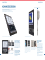
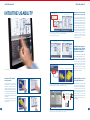
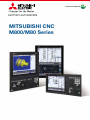
FACTORY AUTOMATION
MITSUBISHI CNC
M800/M80 Series
M800/M80 Series
CNC-DEDICATED CPU
CNC-DEDICATED CPU
Mitsubishi Electric’s first CNC-dedicated CPU, the sum of our industry-leading technologies.
Infinite Possibilities
High productivity, usability and flexibility delivered by breakthrough performance.
The next-generation CNC M800/M80 Series empowers the manufacturing industry with unlimited possibilities
and the capability to create innovative value.
The Best Partner for Your Success
1
CNC-DEDICATED CPU・・・・・・・・・・・・・・・P2
ADVANCED DESIGN・・・・・・・・・・・・・・・・・P3
INTUITIVE USABILITY・・・・・・・・・・・・・・・・P5
CNC LINEUP・・・・・・・・・・・・・・・・・・・・・・・・P7
SYSTEM CONFIGURATIONS・・・・・・・・・・P9
ENHANCED LATHE SYSTEM・・・・・・・・P11
ENHANCED MACHINING
CENTER SYSTEM・・・・・・・・・・・・・・・・・・P13
UNIQUE CUSTOMIZATION・・・・・・・・・・・P15
REINFORCED FUNCTIONAL SAFETY・・P16
SUPPORT FOR AUTOMATION・・・・・・・P17
EXCELLENT MAINTAINABILITY・・・・・・・P19
HARDWARE・・・・・・・・・・・・・・・・・・・・・・・P20
SPECIFICATIONS・・・・・・・・・・・・・・・・・・・P21
DRIVE SYSTEM・・・・・・・・・・・・・・・・・・・・P23
SOFTWARE TOOLS・・・・・・・・・・・・・・・・P25
GLOBAL SERVICE NETWORK・・・・・・・P27
WARRANTY・・・・・・・・・・・・・・・・・・・・・・・P29
YOUR SOLUTION PARTNER・・・・・・・・・P30
Development of
convention-breaking
CNCs
In-depth analysis and
simulations achieve one
volition
Leading the way in today's industrial
globalization, the innovative products of
Mitsubishi Electric continue to exceed
the expectations of users around the
world. The outstanding performance of
our CNC lineup consistently wins
praise from users for their high levels of
productivity, intuitive usability, and
superior functionality. However, to
develop the new M800/M80 Series,
we went back to the drawing board
and completely reexamined our
cutting-edge control technologies. The
result is a breakthrough in the control of
high-speed, high-precision machining.
Pursuit of CNC-dedicated CPU began
with design validation on an
unprecedented scale as well as
high-precision simulations to verify
processing performance.
A c h i e v i n g a l e a p i n p ro c e s s i n g
performance demanded the integration
of innovative technologies beyond
optimizing processor manufacturing
processes. Overcoming numerous
hurdles and maximizing the potential of
the processor, we succeeded in
producing a CNC-dedicated CPU that
achieves unprecedented high-speed
processing performance.
User performance
requirements demand a
commitment to development
Experience the revolutionary
high-speed processing of the
new CNC-dedicated CPU
The story of the new M800/M80 Series
began with conventional development
to produce incremental evolutionary
improvements. But our goal was a
revolutionary leap in CNC performance.
Our project team determined that the
o n l y w a y t o s i g n i fi c a n t l y b o o s t
processing performance and totally
satisfy user demands would be the
creation of a CPU optimized for CNC
control. This insight inspired Mitsubishi
Electric’s first-ever attempt to develop
a CNC-dedicated CPU and opened a
new chapter in CNC development.
Incorporating the CNC-dedicated CPU
in the new series not only results in
phenomenal processing speed, but also
reduces the number of required parts,
leading to fewer possibilities of failure
and increasing product quality. Equipped
with Mitsubishi Electric's first-ever
CNC-dedicated CPU, the long-awaited
M800/M80 Series is the fruit of an
original development process and the
sum of our latest technologies. With the
utmost confidence, we are proud to
introduce the M800/M80 Series and
invite customers to experience
performance of the future today.
The Mitsubishi Electric CNC Development Project Team
Fine segment processing
capacity
M800
M700V
270
168
1.6 times higher
than M700V
[kilo-blocks/min]
High capability in program processing
enables a shorter cycle time.
PLC process capability
(PCMIX value)
M800
M700V
26.0
16.2
1.6 times higher
than M700V
High processing capability of the PLC
enables large-scale ladder logic to be
processed at high speed.
CNC-to-drive
communication capability
M800
M700V
3 times
1 times
3 times higher
than M700V
Optical communication speed
between CNC and drive has been
increased. This improves the system
responsiveness, leading to more
accurate machining.
2
ADVANCED DESIGN
ADVANCED DESIGN
ADVANCED DESIGN
Slim 9.5mm shape (excluding protrusions)
Display and keyboard design have been renewed.
The advanced construction and sophisticated flat profile take machine design to the next level.
The display incorporates a touchscreen as standard specifications,
providing intuitive smartphone-like operation (10.4-type and wider displays).
19-type touchscreen provides easy operability (for M800W Series only)
Software
keyboard
Software
operation panel
Advanced display and keyboard designs
19-type vertical display unit
provides two-split multiple
windows for various applications
Display redesigned for
enhanced visibility of
keyboard
A 19-type vertical display is included
in the M800W Series. The display
provides two-split multiple windows
that can be customized by arranging
the software keyboard, document
viewer or other application.
The display and keyboard have been
redesigned. Measuring only 9.5mm thick
(excluding protrusions), the possibilities of
machine tool design have been expanded. In
addition, their gray-scale colors can be easily
harmonized with machines in different colors.
The surfaces of display and keyboard are
flush, providing beauty and usability as well
as increased operability.
10.4-type and larger displays have
touchscreen made of beautiful, long-life
glass, which allows you easy day-to-day
maintenance.
Vertical mount and horizontal mount
keyboards are included in the product line.
The slim personal computer
unit enables greater flexibility
in operation panel design
Document viewer
3
Memo pad
(handwritten)
M800W Series personal computer unit
boasts 50mm thick (excluding protrusions).
This provides a higher degree of flexibility in
operation panel design.
M700V/M70V
M800/M80
The M800/M80 Series accommodates
an SD card, a relatively easy-to-source
device. The SD card can be inserted or
re m o v e d i n d e p e n d e n t l y o f U S B
memory. The flip-up door provides
greater durability.
Possible to be mounted not only from
the front side of machine tools but also
from the inner side of cabinets.
4
INTUITIVE USABILITY
INTUITIVE USABILITY
INTUITIVE USABILITY
Tools displayed by icons
Advanced universal design
with a focus on ease of use
15-type/19-type
8.4-type/10.4-type
Various features and operation menus are indicated using easy-to-recognize icons.
Tool icons tell you the tool type, left- or right-hand, lifetime
and other information at a glance.
Lathe system
The easy-to-use interface inherited
from M700V/M70V Series has further
advanced, leading to greater visibility
and usability. Iconized features and
operation menus are easy to recognize,
and readily available for anyone to use.
The Simple Monitor screen displays
the information required for lathes and
machining centers respectively in an
enlarged view. The icons on the
screen tell you the status of tools and
spindles. All of these interface
features are worth a try.
Machining center system
Usability in lathe improved
through tool icons, 3D work
simulation for turning and
other dedicated features
Simple screen with narrowed-down information is easy to see from a distance.
Machining center system
Lathe system
Touch operation provides you unprecedented ease of use.
Smartphone-like intuitive
touch operation
The display features a capacitive
touchscreen that is commonly used in
smartphones and tablets, allowing for
intuitive and easy operation. With a
simple flick of the finger, for instance, you
can monitor the desired part of program,
or view and select a menu key on the
next page without the need for tedious
key operation.
In 3D graphic check, you can view a 3D
model at any desired size, in any
desired position.
One of the highlights in M800/M80
Series is improved usability in a lathe.
The tool icons indicate the tool shape
and bit direction in an easy manner,
which can satisfy both inexperienced
and experienced operators. The 3D
graphic check supports for both
turning and milling, so even a complex
program can eas i l y b e check ed
through the 3D simulation.
Reducing leakage of defects
caused by human errors
A click of the menu button navigates you to 3D graphic check of the currently edited program.
For lathe system, the 3D check supports for both milling and turning.
Drag
Program edit (flick)
Supervisor
Operator
Edit machining
program Configure
parameters
Register tool
data, etc.
5
M800/M80 Series has a feature called
"User level-based data protection",
which allows you to set multiple levels
of access permission. Permissible
operation range can be set for each
operator according to their roles in
produ cti on. Thi s can ev er more
effectively prevent operation errors and
other human errors, resulting in less
defect leakage.
6
Pinch-in/Pinch-out
Menu scroll (flick)
Up to 8 levels of access permission helps to prevent you from dispatching defective works.
Permissible operation can be set individually for each access level.
CNC LINEUP
CNC LINEUP
CNC LINEUP
High
Performance
Display unit size
M800W
Premium CNC with
Windows-based display
provides expandability
and flexibility
・S e p a r a t e d t y p e , a c o n t ro l u n i t
separated from display
・Windows-based display with the
latest PC and OS offers excellent
expandability
・Four expansion slots are provided as
standard specifications, allowing for
expansion using option cards
Main Specifications
Lathe
system
19-type
15-type
Touchscreen
(Windows based)
Max. number of axes
(NC axes + Spindles + PLC axes)
Standard:16 Optional:32
8
4
Max. number of part systems
Standard:4
Optional:8
2
Fine segment processing capacity
[kilo-blocks/min]
168
270
Lathe
system
Machining center
system
Max. number of spindles
Touchscreen
(Windows based)
Machining center
system
M800S
High-grade CNC well
suited to high-speed
high-accuracy machining
and multi-axis multi-part
system control
・Panel-in type, a control unit with
integrated display
・Multi-CPU architecture allows for high
performance and high functional
graphics
・Windows-less display provides easy
operability
M80
10.4-type
Touchscreen
Touchscreen
Max. number of axes
(NC axes + Spindles + PLC axes)
Max. number of spindles
Standard:16 Optional:32
8
4
Max. number of part systems
Standard:4
Optional:8
2
Fine segment processing capacity
[kilo-blocks/min]
168
270
Lathe
system
Machining center
system
Max. number of axes
(NC axes + Spindles + PLC axes)
TypeA:12
TypeB:9
TypeA:11
TypeB:9
Max. number of spindles
TypeA:4
TypeB:3
2
Max. number of part systems
TypeA:3
TypeB:2
TypeA:2
TypeB:1
Fine segment processing capacity
[kilo-blocks/min]
TypeA:67.5
TypeB:16.8
TypeA:135
TypeB:16.8
15-type
Standard CNC provides
high productivity
and easy operability
・Panel-in type, a control unit with
integrated display
・Provided in package (TypeA/TypeB)
for easier selection
・Windows-less display provides easy
operability
7
15-type
10.4-type
Touchscreen
Touchscreen
8.4-type
8
Standard
SYSTEM CONFIGURATIONS
SYSTEM CONFIGURATIONS
SYSTEM CONFIGURATIONS
Ethernet
M800S/M80 Series
M800W Series
PC server
Software
・Production control system
・NC Designer2
・NC Trainer2
・NC Trainer2 plus
・NC Explorer
・NC Monitor2
Software
・NC Analyzer2
・NC Configurator2
USB memory
USB memory
SD card
Field Network
・CC-Link ・EtherNet/IP
・PROFIBUS-DP
SD card
SD card
EcoMonitorLight
Display-integrated control unit
& Keyboard
Display
& Keyboard
* Optional part
Control unit
Remote
I/O unit
Manual
pulse
generator
Machine
operation
panel
* Made by the
machine tool builder
9
Drive unit
・MDS-E/EH Series
・MDS-EJ/EJH Series
・MDS-EM Series
This CNC makes it easier to configure
factory automation systems,
and design and build machine tools
・Compatible with a range of field networks, facilitating
connection with peripherals to configure factory automation
systems
・Compatible with MES interface function, through which the
CNC automatically sends data to the production control
system database upon completion of cutting or occurrence
of alarm. This enables more efficient configuration of production
or quality control systems.
・I/O units have been redesigned. The units can be mounted
on DIN rails, and the lineup has been expanded with improved
built-in PLC functionality for I/O control.
・Software tools have been upgraded, and now support
everything from designing to setting up machine tools.
These tools simplify design processes and building machine
tools.
Power
backup
unit
Power
supply
unit
Spindle
motor
Servo motors
・HG Series
・LM-F Series
・TM-RB Series
・SJ-D Series
・SJ-DG Series
・SJ-DL Series
・SJ-BG Series
MC
* Optional part
AC reactor
AC power
supply
10
* Optional parts are not provided as accessories for NC equipment. Please purchase desired components from a Mitsubishi Electric dealership, etc.
ENHANCED LATHE SYSTEM
ENHANCED LATHE SYSTEM
ENHANCED LATHE SYSTEM
M800W
M800S
Turret
Milling features and multi-axis, multi-part system control features have been significantly improved.
Progress has been made in operability, enabling operators to implement ever more complex machining
in an easy and efficient manner.
Milling and turning tools can
be registered in tool
management screen
Tool spindle
M80
Gear
change
mechanism
Servo motors
High-speed high-accuracy control and SSS control are available for milling using lathe system.
A servo motor driven by a servo drive unit can be controlled as a tool spindle.
M800W
【Multiple spindle synchronization set
control】
Tool spindle can be synchronized with
the long workpiece held by the front
and back spindles. The spindles can
implement C axis indexing while
holding the workpiece.
Lathe
Automatic lathe
M800S
【Spindle superimposition
(differential speed tap)】
Lathe turning and center tapping can
be implemented simultaneously.
M800 Series controls up to 8 part systems, 32 axes and 8 spindles.
This CNC provides the advanced multi-axis, multi-part system control features
including loader control using sub-part system, spindle superimposition
and synchronization of multiple spindle sets.
M800W
Multi-tasking lathe
Implement ever more
complex machining in an
easy and efficient manner
Milling features
High-speed high-accuracy control
Super Smooth Surface (SSS) control
Spindle-mode servo motor control
Multi-axis, multi-part system
control features
Supports up to 8 part systems, 32 axes and 8 spindles
Loader control via sub-part system control
Spindle superimposition control
Multiple spindle synchronization set control
User operability
Workpiece coordinate system shift
Easy setup of barrier check parameters
Simple monitor screen showing
narrowed-down information
Features for
large-sized lathes
Re-thread cutting
Thread cutting override
Real-time tuning
Large-sized display
Conversational
programming
Program edit with timing synchronization
between part systems
Interactive cycle insertion
3D program check
Milling features have been improved
through high-speed high-accuracy
control and SSS control. Multi-axis,
multi-part system control features have
also been upgraded. A wide array of
these features help ensure high
productivity.
Significant progress has also been
made in frequently used operation as
well as programming, such as tool
offset and workpiece coordinate
system shift, which allows operators to
easily implement ever more complex
machining.
Another
workpiece
After
cutting
Inertia fluctuates widely
Acceleration
Inverted lathe
Stability
Real-time tuning OFF
Tends to vibrate
(control gain is fixed)
M800S
M80
Real-time tuning ON
Vibration is suppressed
(control gain is automatically adjusted)
Speed
Speed
Time
Acceleration remains
unchanged whether the
workpiece is heavy or light
Time
Acceleration is suited to the
inertia → Acceleration time is
shorter for a lighter workpiece
Real-time tuning helps maintain the stability of large lathes.
This function detects vibration caused by significant fluctuation of work inertia
and automatically adjusts the control gain.
M800W
M800S
High-speed high-accuracy control
features accumulated originally for
machining centers are now available in
lathe system. Fine milling can be
implemented at high speeds on a
lathe.
This CNC enables a servo motor,
instead of a spindle, to act as a tool
spindle. Any of the servo control axes
driven by multi-hybrid drive can be
used as a tool spindle. This contributes
to the downsizing of machine tools.
M80
Vertical lathe
Heavy workpiece
Improved milling features
using a tool spindle
M80
11
Conversational programming, tool measurement, work coordinate system shift and
other features have been improved, making the lathe system significantly easier to use.
Multi-axis multi-part system
control features help to
reduce cycle time and
maintain synchronization
between part systems
M800/M80 Series provides "Spindle
superimposition control, "a feature
that enables simultaneous execution
of turning and center tapping,
although they needed to be executed
individually.
T h e s e f e a t u re s a re e f f e c t i v e i n
eliminating idle time, resulting in a
significant reduction in tact time.
This CNC also offers features that
maintain synchronization between
part systems, which is required for
automatic lathes, in particular. These
enable operators to implement ever
more complex machining safely and
securely.
Significantly easier
programming
Programming has been made much
easier: program edit screen shows the
synchronization points between part
systems in an easy-to-understand
d i s p l a y, a n d c o n v e r s a t i o n a l
programming allows insertion of
canned cycles. After programming,
operators can check the programs
through 3D work simulation before
actual cutting.
12
ENHANCED MACHINING CENTER SYSTEM
ENHANCED MACHINING CENTER SYSTEM
ENHANCED MACHINING
CENTER SYSTEM
SSS control has further evolved, realizing high-speed, high-accuracy, high-quality machining.
In addition, this CNC offers features that bring out the full potential of each axis and minimize non-cutting time,
leading to higher productivity.
M800W
Large
tolerance
5min 15sec
Medium
tolerance
5min 46sec
M800S
High productivity and
high quality are our
primary focus
M80
Small
tolerance
6min 34sec
Tolerance control function provides a smooth motion within specified error tolerances.
Desired machining results can be achieved using simple parameter adjustment.
M800W
M800S
When operated by
linear axes
When operated by
When operated by
linear and rotary axes rotary axes
Speed
Speed
Acceleration
Speed
Acceleration
Low
Acceleration
Low
Low
Time
Vertical machining center
Tapping center Horizontal machining center
Speed
Time
Speed
Acceleration
Speed
Acceleration
High
Acceleration
Medium
Low
Time
32min 48sec
Time
Time
Time
29min 30sec
"Variable-acceleration pre-interpolation acceleration/deceleration"
optimizes the acceleration in accordance with the axis motion.
M800W
Standard
model
Gantry-type machining center
5-axis control machine
Machining accuracy
6min 34sec
5min 46sec
6min 37sec
Low
Long
13
SSS control
Machining time
SSS-4G control
Short
M800/M80 Series offers SSS
4th-generation (SSS-4G) control,
enabling high-speed, high-accuracy,
high-quality machining. SSS-4G
control provides features that are
effective in reducing tact time, including
optimal acceleration/deceleration
suited to each axis' characteristics. In
addition, SSS-4G is capable of
reducing machine vibration during
high-speed cutting.
SSS-4G control allows for greater
cutting accuracy in the same length of
time, or shorter cutting time with the
s a m e d e g re e o f a c c u r a c y w h e n
compared to our previous models.
Circularity
1.1㎛
Position
control
Speed
control
M80
Circularity
0.7㎛
Mechanical
system
Position
command
High-speed, high-accuracy,
high-quality cutting
through SSS-4G control
High
Feed-forward
generation
M800S
Current
control
"OMR-FF control" makes servo control smoother and more accurate,
enabling optimal position loop gain adjustment suited to each axis.
M800W
No overlap
Speed
0deg corner
(straight line)
G0
M800S
45deg corner
90deg corner
G0
N2
N2
N2 Tolerance
Time
With overlap
N1
Speed
Speed
G0
M80
G0
N1
Time
N1
Speed
N2
N1
Time
N1
Speed
N2
Time
N1
N2
Time
Rapid traverse block overlap function makes it possible to reduce non-cutting time.
The overlap varies according to the path to keep the tolerance constant.
CNC-dedicated CPU is incorporated
in the M800/M80 Series, providing
significantly improved short segment
processing capability. The benefits are
not limited to improvements in basic
performance alone. The Tolerance
Control function enables operators to
achieve high-quality surfaces simply
by specifying the desired dimensional
accuracy. This feature takes machining
to a whole new level.
M800/M80 Series brings
out the full potential
of machine tools
M800/M80 Series provides new
features that can maximize the full
potential of machine tools, including:
Variable-acceleration pre-interpolation
acceleration/deceleration provides
optimized acceleration, with each axis'
characteristics fully exercised. For
example, allowing a linear axis to
accelerate irrespective of rotary axis
responsiveness.
"OMR-FF control" allows for optimal
position loop gain adjustment suited to
each axis, leading to smoother and
more accurate cutting.
Other than the above, this CNC has
new functionality effective for higher
productivity, including "Rapid traverse
block override function" that helps
reduce non-cutting time by overlapping
feed blocks.
Necessary features are
available on your
machine. M80 Series
includes SSS control and
inclined surface
machining features.
The SSS control function provides
smoother surfaces at higher speeds and
the inclined surface machining control
function makes it possible to issue
normal program commands to an
arbitrary plane (inclined surface) in space.
These and various other features are
incorporated in the M80 Series.
14
UNIQUE CUSTOMIZATION
REINFORCED FUNCTIONAL SAFETY
UNIQUE CUSTOMIZATION
A high level of screen customization is attainable more easily in a shorter period of time.
Highly scalable hardware and advanced drawing application make it possible to increase the added value of machine tools.
19-type vertical display
boosts the added value of
machine tools
M800W
Possible to customize the
key type and layout
Possible to customize
the operation panel to
machine tools
Possible to add and erase original application(s)
M800W Series is equipped with a 19-type vertical display with a two-split multi-window screen.
Home application in the lower half can freely be customized.
M800S
M80
Additional SD memory card interface on backside of display.
An SD card can store large-capacity machining programs and custom screen data.
Possible to arrange the menus
M800S
M80
【Selective display】
Possible to change part of the items on the Monitor screen
Standard screens can be customized using the selective display and rearranging menus.
Screens matching operators' preferences and needs enable even greater ease of use.
M800W
M800S
M80
【Wide-ranging items to set】
Possible to set the tool data to distinguish
tools such as tool name, tool ID, and number
of flutes.
All of the data can be read and written
through machining program or ladder logic.
【Addition of custom data】
Custom data can be added. It is also possible
to specify the item name.
15
M800/M80 Series provides a range of safety features collectively called the Smart Safety Observation Function.
This function has achieved full conformity with the safety standards
that cover the entire system including CNC, drive, I/O, sensors and communication.
Smart safety observation function
Safety-related I/O observation
Safely-Limited Speed (SLS)
Safe Operating Stop (SOS)
Safe Brake Control/Safe Brake Test (SBC/SBT)
Safe Stop (SS1/SS2)
Tool-related information is collected and centrally managed on the Tool Management Screen.
A wide range of setting items such as tool name and tool ID are readily available.
It is also possible to add custom data.
The panel-in type CNC with integrated
display has the SD card interface on
the back of the display.
SD card can accommodate large-capacity
machining programs, and large-capacity
graphic data for custom screens, which
l e a d s t o i n c re a s e d p o s s i b i l i t i e s o f
customization.
Customize the standard
screens as per the
preference of operators
Each operator has their own set of
frequently used menus. This CNC
allows operators to rearrange their
menus and hide any unused ones so
they can easily navigate to their desired
screen.
This CNC has a function called
Selective Display, which enables partial
customization of the Monitor screen.
Operators can constantly view and
monitor Tool offset, Work offset,
Common variable or other commonly
used functions.
Emergency stop observation
Safely-Limited Position (SLP)
Safe Speed Monitor (SSM)
Safe Cam (SCA)
Safe Torque Off (STO)
Functional safety system
can be configured easily.
Safety communication enables
the use of wire-saving configurations
Not required
Drive
unit
Support for large-capacity
custom data using the SD
memory on the back of
display
【SD card interface in display unit】
Large-capacity machining program
Custom screen data
Backup data
M800W
The display shows the standard CNC
screen on the upper half, while offering
the lower half (home application) to be
freely customized. It is also possible to
add some originality to machines to
increase their added value. However, it
is difficult to design the whole screen at
the same time. This screen layout can
satisfy such needs.
Combined with customers' ideas, the
possibilities are infinite.
REINFORCED FUNCTIONAL
SAFETY
Safety
communication
Door
signal
Remote
I/O unit
Emergency
stop
Operation panel
I/O Unit
Safety I/O
Capable of monitoring redundant
door and emergency stop signals
with no need for dedicated safety
circuit
Power supply
unit
Safety
communication
CNC
Not required
Not required
Redundant two-channel
STO is built into the
drive, making it possible
to use less wiring
Motor
Equipped with the
safety-compatible sensor
Compliant with a range of safety standards,
equipped with the drive safety features required for machine tools
The Smart Safety Observation Function conforms to EC
Machinery Directive (2006/42/EC) and meets the
following safety standard requirements. The function
has also obtained the Type Approval Certificate from
TÜV SÜD (German certification authority) with regard to
the conformity with the safety standards.
【Compatible functional/product safety standards】
・EN ISO 13849-1 : 2008 (PLd, Cat.3) ・IEC 61508-1~3 : 2010 (SIL 2) ・EN 62061 : 2005 (SIL CL 2)
・EN 61800-5-1 : 2007 ・EN 60204-1 : 2006
16
SUPPORT FOR AUTOMATION
SUPPORT FOR AUTOMATION
SUPPORT FOR AUTOMATION
ENHANCED TRACEABILITY
M800W
M800S
M80
CC-Link
Mount on
control unit
With the aim of configuring factory
automation systems, compatibility with
a range of field networks has been
implemented, enabling connection to
peripheral equipment and devices.
Insert the option card into the standard
expansion slot of the M800W Series
CNC or on the back side of the display
for the M800S/M80 Series.
CC-Link
card
Supports automation needs
Connectable to a range of field networks
Mount in
expansion slot
Compatible with CC-Link (master/slave), PROFIBUS-DP (master)
and EtherNet/IP (scanner). Possible to connect to peripheral equipment
and devices conforming to a range of field networks.
①Each channel accommodates up to 32
units (64 stations, 2048 points)
②Devices can be allocated to each
station using the parameters
Alarm list
M800W
M800S
M80
The I/O unit makes
it more efficient to
design and build
machine tools
①All wiring is on
the front
②Possible to be
mounted on DIN
rail
Trend graph
Traceability
Renewed I/O communication method allows for the control of up to 64 stations
and 2,048 points per channel.
Various peripheral equipment can be controlled by the CNC alone.
M800W
Ladder logic
for machine tool
17
Machine tool
Automation of small-scale line easily realized
M
device
can be
shared
Needs for automation are increasing, which can be realized more easily with lower cost.
M800/M80 Series CNCs are equipped with
the MES interface function, through which
the CNC automatically sends SQL
statements to the production control system
database upon completion of cutting or
occurrence of an alarm. This can significantly
increase traceability throughout the factory.
This transparency helps optimize production
planning and management.
Quality control can also be easier through
visualization of alarm history and the
production results based on the basic unit
specific to each workpiece.
In addition, when control is combined with
the EcoMonitorLight power consumption
monitor, operators can monitor not only
CNC status, but also the energy consumed
by the machines.
M80
Individual ladder development and management
Project 1
Workpiece
Improved traceability
helps to visualize
factory-wide operation
M800S
Production control system
Ladder logic for
peripheral equipment
Possible to monitor production results based on the basic
unit specific to each workpiece, as well as the alarm history
When cutting is complete
Work ID, Cutting start/end
time, Maximum spindle load,
Power consumption, Tool
number, Tool offset, etc.
During alarm
Work ID, Time of alarm
occurrence, Details of
alarm, Tool number,
Tool offset, etc.
EcoMonitorLight
MES interface
function
Multi-project PLC enables control of ladder logic for peripheral equipment separately
from that for machine tools. This leads to efficient development and management of
ladder logics for peripheral equipment.
M800W
Group 1
Group 2
M800S
M80
Loader
ModbusRTU
Power
consumption
Upon completion of cutting or occurrence
of alarm, CNC sends the data collected to
the database.
Renewed I/O units and
built-in PLC functionality
make it easier to control
and manage peripheral
equipment
I/O units have been redesigned. The
renewed I/O communication method
makes it possible to significantly
increase the maximum number of
contact points per channel, enabling a
number of peripheral equipment and
devices to be controlled by CNC alone.
In addition, built-in PLC functionality for
I/O control has been improved. This
CNC supports Multi-project PLC, a
feature that enables ladder logics for
peripheral equipment to be managed
separately from those for machine
tools. This creates a more efficient
environment for operators working
together in developing and managing
ladder logics.
Conveyor
Project 2
LAN
Machining information
Compatible with a range
of field networks that
facilitate connection to
peripheral equipment
If an alarm occurs on the
loader axis, only the
loader is stopped.
New feature capable of
stopping peripheral
equipment incorporated
M800/M80 Series has a feature called
Machine Group-based Alarm Stop,
which stops operation of individual
machine groups if an alarm occurs
when control is combined with the
MDS-E/EM/EJ Series.
This feature allows continuation of
machining even when an alarm occurs
on a loader, magazine or other peripheral
equipment.
18
Needs for automation are increasing, which can be realized more easily
and with lower cost.
During an alarm, operation of individual machine groups can be stopped.
Machining is not interrupted when an alarm occurs on peripheral equipment (e.g., loader).
EXCELLENT MAINTAINABILITY
HARDWARE
EXCELLENT MAINTAINABILITY
HARDWARE
The number of spare parts for M800/M80 Series CNCs has been reduced,
environmental resistance improved and assembly simplified to provide higher efficiency in maintenance.
Control unit
M800W Series
(Separated type)
180
90
M800S/M80 Series
(Integrated type)
Separated from display
Integrated on back of display
Control unit
380
No-fan structure
・Heat generation suppressed by
introducing an original CPU
・Spare parts reduced
M800W
Display unit
Display panel
M800S
M80
Display
Keyboard
Control unit
M800W Series
M800S Series
19-type
Touchscreen
ー
440
400
15-type
Touchscreen
400
Front-side wiring
・All wiring can be done from the front side of the unit
・Assembly simplified
320
320
320
140
140
140
290
290
10.4-type
Touchscreen
220
220
160
160
FCU8-KB047
Clear key
DIN rail mount
・All types are mountable on DIN rails
(can also be attached using screws)
290
10.4-type
Touchscreen
8.4-type
19
400
FCU8-KB081
Clear key
Personal computer unit
(M800W Series only)
I/O unit
M80 Series
365
No hard-disk drive
・Vibration resistance improved
Capacitive touch-screen panel
・Easy operation and longer
service life
Separated front I/F ports
・Protect the SD card slot
from any fluid even while a
USB memory device is
inserted
ECC-embedded memory
・Memory error detection and
correction possible with built-in ECC
・Noise tolerance improved
Control unit
FCU8-KB046
Clear key
FCU8-KB026
Clear key
220
140
290
140
260
140
220
200
20
SPECIFICATIONS
SPECIFICATIONS
SPECIFICATIONS
○Standard △Optional □Selection
○Standard △Optional □Selection
Lathe system
M800W Series
M850S
M830S
Max. number of axes (NC axes + Spindles + PLC axes)
○16
△32
○16
△32
○16
△32
Max. number of NC axes (in total for all part systems)
○16
△32
○16
△32
○16
△32
Max. number of spindles
8
8
Max. number of PLC axes
8
8
Number of simultaneous contouring control axes
8
Max. number of NC axes in a part system
M800S Series
M80 Series
M850W
M830W
M850S
M830S
TypeA
TypeB
12
9
Max. number of axes (NC axes + Spindles + PLC axes)
○16
△32
○16
△32
○16
△32
○16
△32
11
9
○16
△32
10
7
Max. number of NC axes (in total for all part systems)
16
16
16
16
8
5
8
8
4
3
Max. number of spindles
4
4
4
4
2
2
8
8
6
6
Max. number of PLC axes
8
8
8
8
6
6
4
8
4
4
4
Number of simultaneous contouring control axes
8
4
8
4
4
4
8
8
8
8
8
5
Max. number of NC axes in a part system
8
8
8
8
8
5
Max. number of part systems
○4
△8
○4
△8
○4
△8
○4
△8
3
2
Max. number of part systems
2
2
2
2
2
1
Control unit-side High-speed program server mode
△
△
−
−
−
−
Control unit-side High-speed program server mode
△
△
−
−
−
−
Display unit-side High-speed program server mode
△
△
△
△
○
○
Display unit-side High-speed program server mode
△
△
△
△
○
○
Front-side SD card mode
○
○
○
○
○
○
Front-side SD card mode
○
○
○
○
○
○
○0.1μm
△1nm
○0.1μm
△1nm
○0.1μm
△1nm
○0.1μm
△1nm
0.1μm
0.1μm
○0.1μm
△1nm
○0.1μm
△1nm
○0.1μm
△1nm
○0.1μm
△1nm
0.1μm
0.1μm
1nm
1nm
1nm
1nm
1nm
1nm
1nm
1nm
1nm
1nm
1nm
1nm
Max. number of tool offset sets
○128 sets
△999 sets
○128 sets
△999 sets
○128 sets
△999 sets
○128 sets
△999 sets
256 sets
99 sets
Max. number of tool offset sets
○200 sets
△999 sets
○200 sets
△999 sets
○200 sets
△999 sets
○200 sets
△999 sets
400 sets
400 sets
Max. PLC program memory capacity [steps]
○128000
△512000
○128000
△512000
○128000
△512000
○128000
△512000
64000
32000
Max. PLC program memory capacity [steps]
○128000
△512000
○128000
△512000
○128000
△512000
○128000
△512000
64000
32000
Multi-project PLC (max. number of projects)
○1
△6
○1
△6
○1
△6
○1
△6
3
1
Multi-project PLC (max. number of projects)
○1
△6
○1
△6
○1
△6
○1
△6
3
1
Touch gesture operation
○
○
○
○
○
○
Touch gesture operation
○
○
○
○
○
○
User level-based protection
△
△
△
△
○
○
User level-based protection
△
△
△
△
○
○
Workpiece coordinate system shift
○
○
○
○
○
○
Workpiece coordinate system shift
−
−
−
−
−
−
3D program check
○
○
○
○
○
○
3D program check
○
○
○
○
○
○
Interactive cycle insertion
△
△
△
△
○
○
Interactive cycle insertion
−
−
−
−
−
−
Multiple spindle synchronization set control
○
○
○
○
○
○
Multiple spindle synchronization set control
−
−
−
−
−
−
Spindle superimposition control
△
△
△
△
○
−
Spindle superimposition control
−
−
−
−
−
−
High-accuracy control
△
△
△
△
○
−
High-accuracy control
△
△
△
△
○
○
High-speed high-accuracy control I
△
△
△
△
○
−
High-speed high-accuracy control I
△
△
△
△
○
○
High-speed high-accuracy control II
△
△
△
△
○
−
High-speed high-accuracy control II
△
△
△
△
○
−
SSS control
△
△
△
△
○
−
SSS control
△
△
△
△
○
−
Tolerance control
−
−
−
−
−
−
Tolerance control
△
△
△
△
○
−
Variable-acceleration pre-interpolation acceleration/deceleration
−
−
−
−
−
−
Variable-acceleration pre-interpolation acceleration/deceleration
△
△
△
△
−
−
OMR-FF control
△
△
△
△
○
−
OMR-FF control
△
△
△
△
○
○
Rapid traverse block overlap
△
△
△
△
○
○
Rapid traverse block overlap
△
△
△
△
○
○
Spindle-mode servo motor control
△
△
△
△
○
○
Spindle-mode servo motor control
△
△
△
△
○
○
Real-time tuning 1 (speed gain changeover)
△
△
△
△
○
−
Real-time tuning 1 (speed gain changeover)
△
△
△
△
○
−
Real-time tuning 2 (rapid traverse time constant changeover)
△
△
△
△
○
−
Real-time tuning 2 (rapid traverse time constant changeover)
△
△
△
△
○
−
Tool center point control
−
−
−
−
−
−
Tool center point control
△
−
△
−
−
−
Inclined surface machining command
△
△
△
△
○
−
Inclined surface machining command
△
△
△
△
○
−
3-dimensional manual feed
−
−
−
−
−
−
3-dimensional manual feed
△
△
△
△
○
−
R-Navi
−
−
−
−
−
−
R-Navi
△
△
△
△
○
−
CC-Link (Master/Slave)
□
□
□
□
□
□
CC-Link (Master/Slave)
□
□
□
□
□
□
PROFIBUS-DP (Master)
□
□
□
□
□
□
PROFIBUS-DP (Master)
□
□
□
□
□
□
EtherNet/IP (Scanner)
□
□
□
□
□
□
EtherNet/IP (Scanner)
□
□
□
□
□
□
MES interface function
△
△
△
△
○
○
MES interface function
△
△
△
△
○
○
EcoMonitorLight connection
□
□
□
□
□
□
EcoMonitorLight connection
□
□
□
□
□
□
Machine group-based alarm stop
△
△
△
△
○
−
Machine group-based alarm stop
△
△
△
△
○
−
Smart safety observation
△
△
△
△
−
−
Smart safety observation
△
△
△
△
−
−
Least control increment
TypeA
M800W Series
Number of control axes
M830W
○16
△32
M80 Series
TypeB
Number of control axes
M850W
Least command increment
21
Machining center system
M800S Series
Least command increment
Least control increment
Refer to the specifications manuals for details.
22
DRIVE SYSTEM
DRIVE SYSTEM
DRIVE SYSTEM
Spindle motor
Drive unit
High-performance Servo/
Spindle Drive Units
MDS-E/EH Series
・The servo control-dedicated core processor
realizes an increase in control speed, leading
to improved basic performance. When combined
with a higher resolution motor sensor and
enhanced high-speed optical communication,
this drive contributes to high-speed, high-accuracy
control.
・Motor power connector comprises an
anti-misinsertion mechanism. This helps to
eliminate connection errors.
・Improved diagnostic and preventive-maintenance
features.
・Safe Torque Off (STO) and Safe Brake Control
(SBC) are supported in effort to enhance
safety features.
Multi-hybrid
Drive Units
MDS-EM Series
・The multi-hybrid drive unit is capable of
driving a maximum of three servo axes and
one spindle. This contributes to the
downsizing of machines and offers technical
advantages.
・Motor power connector comprises an
anti-misinsertion mechanism. This helps to
eliminate connection errors.
・Safe Torque Off (STO) and Safe Brake Control
(SBC) are supported in effort to enhance
safety features.
All-in-one
compact drive units
MDS-EJ/EJH Series
・Ultra-compact drive units with built-in power
supplies contribute to reduced control
panel size.
・The servo control-dedicated core processor
realizes an increase in control speed, leading
to improved basic performance. When combined
with a higher resolution motor sensor and
enhanced high-speed optical communication,
this drive contributes to high-speed, high-accuracy
control.
・Safe Torque Off (STO) and Safe Brake Control
(SBC) are supported in effort to enhance
safety features.
・MDS-EJH 400V system drive unit is available
(Note 1).
High-performance
Spindle Motor
SJ-D Series
・Motor energy loss has been significantly
reduced by optimizing the magnetic circuit.
・High-speed bearing incorporated as a
standard feature helps to achieve higher
s p e e d , l o w e r v i b r a t i o n a n d i m p ro v e d
durability.
・Range:
Normal SJ-D Series 3.7 to 11 [kW]
Compact & light SJ-DJ Series 5.5 to 15 [kW]
・Maximum speed 10,000 or 12,000 [r/min]
High-output, High-torque
Spindle Motor
SJ-DG Series
・Addition of S3 rating (%ED rating) has improved
output and torque acceleration/deceleration
characteristics.
・Balance adjustment ring has been added to
the counter-load side for fine tuning.
・Range S3 rating: 5.5 to 15 [kW]
・Maximum speed 10,000 or 12,000 [r/min]
Low-inertia, High-speed
Spindle Motor
SJ-DL Series
・The spindle motors are dedicated to tapping
machines requiring faster drilling and
tapping.
・The latest design technologies have made it
possible to attain lower vibration and greater
rigidity even with the lighter weight.
・Range 0.75∼7.5
[kW]
Servo motors
Medium-inertia, high-accuracy
and high-speed motors
HG Series
23
・Sensor resolution has been significantly
improved. The servo motors, which boast
smooth rotation and outstanding acceleration
capabilities, are well-suited to serve as feed
axes of machine tools.
・Range 0.5 to 9 [kW]
・Maximum speed: 4,000 or 5,000 [r/min]
・Safety support sensors are included as
standard specification. Sensor connectors
are screw-locked and have enhanced
vibration resistance. Three sensor resolutions
(i.e., 1, 4 and 67 million pulses/rev) are available.
Linear
Servo Motor
LM-F Series
・Use in clean environments is possible since
no ball screws are used, eliminating possible
contamination from grease.
・Elimination of transmission mechanisms,
including backlash, enables smooth and
quiet operation even at high speeds.
・Dimensions:
Length: 290 to 1,010 [mm]
Width: 120 to 240 [mm]
Direct Drive
Servo Motor
TM-RB Series
・High-torque, direct-drive motor combined
with high-gain control provides quick
acceleration and positioning, which makes
rotation smoother.
・Suitable for rotary axes that drive tables or
spindle heads.
・Range:
Maximum torque: 36 to 1,280 [N·m]
Built-in
Spindle Motor
SJ-BG Series
・The electrical design has been optimized to
increase the continuous rated torque per
unit volume, contributing to the downsizing
of spindle units.
・A mold with cooling jacket is available as
an optional feature.
24
(Note 1) For servo motors only
SOFTWARE TOOLS
SOFTWARE TOOLS
SOFTWARE TOOLS
●Design
●Setup
Set the machine constants according
to the following explanation.
Calculation results
of the spindle acceleration/
deceleration times
Check the contents
of the parameters
in the help section.
【NC Servo Selection】
Input the machine constants for selection of the optimum
servo motor.
This function automatically calculates spindle
acceleration/deceleration times and selects the optimum
power supply unit.
Check and setup
the parameter
list using a
computer.
【NC Configurator2】
NC parameters required for NC control or machine
operation can be edited on a computer. Also possible to
create initial parameters simply by inputting the machine
configuration.
Servo motor selection
NC Configurator2
The spindle acceleration/
deceleration times are shown
in a graph.
Combine the parts to
customize the screen
without programming.
Adjusting with simple
parameter settings
【NC Designer2】
Customize buttons
with original pictures.
Customize a screen using
NC Designer2 and check its
operation using NC Trainer2 plus.
NC Designer2
【NC Analyzer2】
Servo parameters can be adjusted automatically by
measuring and analyzing the machine's characteristics.
Measurement and analysis can be done by running a
servo motor using the machining program for adjustment,
or using the vibration signal. This function can sample
various types of data.
Support
【NC Trainer2 plus】
NC Trainer2 plus supports customization development; it
helps to program the ladder programming of the user PLC
to be developed by machine tool builders and debug it
and check the operations of customized screens.
NC Trainer2 plus
Results displayed
in bode diagram
We provide a developmental environment where the MTB
can customize screens easily.
Two types of screen development methods are available;
the interpreter system (programming without C++) for
simple screen development, and the compiler system
with a complex controller (programming with C++).
●Operational
Edit PLC program with
PLC development tool
of NC Trainer2 plus.
Servo parameters
are adjusted
automatically
Machining
data file
Drag and drop to transfer machining data files
NC Explorer
NC Trainer2 plus
【NC Explorer】
CNC machining data files can be manipulated using
Windows® Explorer on a computer when the computer is
connected to multiple CNCs via Ethernet.
Ethernet
Machining data file
NC Explorer
●Training
Monitor the status
of multiple CNCs
on one computer
Education
【NC Monitor2】
【NC Trainer2 / NC Trainer2 plus】
Operation check
Results
・Put skills obtained into practice
・Smooth start-up
・Quick setup/machining
This is an application for operating the CNC screen and
machining programs on a computer without the CNC
control unit or a special display unit. It can also be used for
learning CNC operation and checking machining programs.
The machining programs created on NC Trainer2/NC
Trainer2 plus can be used on actual CNCs.
Ethernet
Taking advantage of the network in a plant, CNC operation
status can be monitored from remote locations. Several
CNCs can be connected and monitored simultaneously.
NC Monitor2
25
26
For details regarding each software, refer to the Software Tools Catalog (BNP-A1224).
GLOBAL SERVICE NETWORK
GLOBAL SERVICE NETWORK
GLOBAL SERVICE NETWORK
■:Production site ●:FA Center ○:Service office
We provide satisfying after-sales services worldwide, aiming to be your best partner.
CHINA
AMERICA
・MITSUBISHI ELECTRIC AUTOMATION
・MITSUBISHI ELECTRIC AUTOMATION INC.
・China (Beijing) Service Center ・China (Tianjin) Service Center
・West Region Service Center
・China (Chengdu) Service Center
・Michigan Service Satellite
(AMERICA FA CENTER)
Central Region Service Center
TEL: +1-847-478-2500
FAX: +1-847-478-2650
(CHINA) LTD. (CHINA FA CENTER)
China (Shanghai) Service Center
TEL: +86-21-2322-3030
FAX: +86-21-2308-3000
・South Region Service Center
・China (Shenzhen) Service Center
・Ohio Service Satellite
・China (Shenyang) Service Satellite ・China (Wuhan) Service Satellite
・China (Changchun) Service Satellite
・Minnesota Service Satellite
・Northern CA Satellite
JAPAN
・Pennsylvania Service Satellite
・MITSUBISHI ELECTRIC CORPORATION
・Connecticut Service Satellite
(TOKYO HEAD OFFICE, NAGOYA WORKS) ・RYODEN KOKI ENGINEERING CO., LTD
・Texas Service Satellites
・Tennessee Service Satellite
(HEAD QUARTER)
TEL:+81-52-722-6620 / FAX:+81-52-722-6662
EUROPE
・MITSUBISHI ELECTRIC AUTOMATION
KOREA CO., LTD. (KOREA FA CENTER)
Korea Service Center
TEL: +82-2-3660-9602 / FAX: +82-2-3664-8668
TEL: +49-2102-486-0
FAX: +49-2102-486-5910
・Germany Service Center
・Italy Service Center
・Italy (Padova) Service Satellite
・U.K. Service Center
・Spain Service Center
ASEAN
・Malaysia (KL) Service Center
・Malaysia (Johor Baru) Service Center
・Czech Republic Service Center
・Philippines Service Center
・Russia Service Center
・Ukraine (Kharkov) Service Center
・Ukraine (Kiev) Service Center
・Belarus Service Center
・South Africa Service Center
・Monterrey Service Satellite
・MITSUBISHI ELECTRIC TAIWAN CO., LTD.
(ASEAN FA CENTER)
Singapore Service Center
TEL: +65-6473-2308 / FAX: +65-6476-7439
・Turkey Service Center
・Bulgaria Service Center
・Mexico Region Service Center
TAIWAN
・MITSUBISHI ELECTRIC ASIA PTE. LTD.
・Poland Service Center
・Sweden Service Center
・Korea Taegu Service Satellite
・France Service Center
・France (Lyon) Service Satellite
・Canada Region Service Center
・Canada Service Satellite
KOREA
・MITSUBISHI ELECTRIC EUROPE B.V.
(EUROPE FA CENTER)
・Florida Service Satellite
INDIA
・MITSUBISHI ELECTRIC INDIA PVT. LTD.
(INDIA FA CENTER)
India (Gurgaon) Service Center
・India (Pune) Service Center
・India (Bangalore) Service Center
TEL: +91-80-4020-1600
FAX: +91-80-4020-1699
(TAIWAN FA CENTER)
Taiwan (Taichung) Service Center (Central Area)
TEL: +886-4-2359-0688 / FAX: +886-4-2359-0689
THAILAND
・MITSUBISHI ELECTRIC FACTORY
AUTOMATION (THAILAND) CO.,LTD
(THAILAND FA CENTER)
Thailand Service Center
TEL: +66-2-682-6522-31
FAX: +66-2-682-6020
VIETNAM
・MITSUBISHI ELECTRIC VIETNAM CO.,LTD
Vietnam (Ho Chi Minh) Service Center
・Vietnam (Hanoi) Service Satellite
・Taiwan (Taipei) Service Center (North Area)
・Taiwan (Tainan) Service Center (South Area)
・MELCO CNC do Brasil Comércio e Serviços S.A
Brazil Region Service Center
Indonesia Service Center
OCEANIA
・MITSUBISHI ELECTRIC AUSTRALIA LTD.
Australia Service Center
TEL: +61-2-9684-7269 / FAX: +61-2-9684-7245
FA Center
Production site
BRAZIL
INDONESIA
・PT. MITSUBISHI ELECTRIC INDONESIA
Korea FA Center
We have established FA Centers that manage service centers and service satellites in each area to enhance our
service quality by providing trainings for engineers and enhancing service parts and repair facilities.
China FA Center
Taiwan FA Center
Thailand FA Center
27
28
Nagoya Works
Mitsubishi Electric Automation Manufacturing (Changshu) Co., Ltd.
India FA Center
ASEAN FA Center
Europe FA Center
American FA Center
Refer to the Mitsubishi Electric FA Global Service Catalog (K-001) for location, contact and other information of each office.
WARRANTY
YOUR SOLUTION PARTNER
WARRANTY
YOUR SOLUTION PARTNER
Please confirm the following product warranty details before using MITSUBISHI CNC.
1. Warranty Period
and Coverage
Should any fault or defect (hereafter called
"failure") for which we are liable occur in this
product during the warranty period, we shall
provide repair services at no cost through the
distributor from which the product was
purchased or through a Mitsubishi Electric
service provider. Note, however that this shall
not apply if the customer was informed prior
to purchase of the product that the product
is not covered under warranty. Also note that
we are not responsible for any on-site
readjustment and/or trial run that may be
required after a defective unit is replaced.
[Warranty Term]
The term of warranty for this product shall be
twenty-four (24) months from the date of delivery
of product to the end user, provided the product
purchased from us in Japan is installed in Japan
(but in no event longer than thirty (30) months,
Including the distribution time after shipment
from Mitsubishi Electric or its distributor).
Note that, for the case where the product
purchased from us in or outside Japan is
exported and installed in any country other
than where it was purchased; please refer
to "2. Service in overseas countries" as will
be explained.
29
[Limitations]
(1) The customer is requested to conduct an
initial failure diagnosis by him/herself, as a
general rule. It can also be carried out by us or
our service provider upon the customer’s
request and the actual cost will be charged.
(2) This warranty applies only when the
conditions, method, environment, etc., of use
are in compliance with the terms and conditions
and instructions that are set forth in the
instruction manual, user’s manual, and the
caution label affixed to the product, etc.
(3) Even during the term of warranty, repair costs
shall be charged to the customer in the following
cases:
(a) a failure caused by improper storage or
handling, carelessness or negligence, etc.,
or a failure caused by the customer’s
hardware or software problem
(b) a failure caused by any alteration, etc., to the
product made by the customer without
Mitsubishi Electric’s approval
(c) a failure which may be regarded as avoidable,
if the customer’s equipment in which this
product is incorporated is equipped with a
safety device required by applicable laws or has
any function or structure considered to be
indispensable in the light of common sense in
the industry
(d) a failure which may be regarded as avoidable
if consumable parts designated in the instruction
manual, etc. are duly maintained and replaced
(e) any replacement of consumable parts
(including a battery, relay and fuse)
(f) a failure caused by external factors such as
inevitable accidents, including without limitation
fire and abnormal fluctuation of voltage, and
acts of God, including without limitation
earthquake, lightning, and natural disasters
(g) a failure which is unforeseeable under
technologies available at the time of shipment of
this product from our company
(h) any other failures which we are not
responsible for or which the customer
acknowledges we are not responsible for
2. Service in Overseas
Countries
If the customer installs the product
purchased from us in his/her machine or
equipment, and export it to any country
other than where he/she bought it, the
customer may sign a paid warranty
contract with our local FA center.
This falls under the case where the product
purchased from us in or outside Japan is
exported and installed in any country other
than where it was purchased.
For details please contact the distributor
from which the customer purchased the
product.
3. Exclusion of Responsibility
for Compensation against
Loss of Opportunity, Secondary Loss, etc.
Whether during or after the term of warranty,
we assume no responsibility for any
damages arising from causes for which we
a re n o t re s p o n s i b l e , a n y l o s s e s o f
opportunity and/or profit incurred by the
customer due to a failure of this product, any
damages, secondary damages or
compensation for accidents arising under
specific circumstances that either foreseen
or unforeseen by Mitsubishi Electric, any
damages to products other than this
product, or compensation for any
replacement work, readjustment and startup
test run of on-site machines or any other
operations conducted by the customer.
Low voltage: MCCB, MCB, ACB
Medium voltage: VCB, VCC
4. Changes in Product
Specifications
Specifications shown in our catalogs,
manuals or technical documents are
subject to change without notice.
Power monitoring, energy management
Mitsubishi Electric offers a wide range of automation equipment from PLCs and HMIs to
CNC and EDM machines.
5. Product Application
(1) For the use of this product, its applications
should be those that may not result in a serious
damage even if any failure or malfunction occurs
in the product, and a backup or fail-safe function
should operate on an external system to the
product when any failure or malfunction occurs.
(2) Mitsubishi CNC is designed and
manufactured solely for applications to machine
tools to be used for industrial purposes.
Do not use this product in any applications other
than those specified above, especially those
which are substantially influential on the public
interest or which are expected to have significant
influence on human lives or properties.
* Trademarks
MELDAS, MELSEC, EZSocket, EZMotion, iQ
Platform, MELSOFT, GOT, CC-Link, CC-Link/LT
a n d C C - L i n k I E a re e i t h e r t r a d e m a r k s o r
registered trademarks
of Mitsubishi Electric Corporation in Japan
and/or other countries.
Ethernet is a registered trademark of Xerox
Corporation in the United States and/or other
countries.
Microsoft® and Windows® are either trademarks
or registered trademarks of Microsoft
Corporation in the United States and/or other
countries.
SD logo and SDHC logo are either registered
trademarks or trademarks of LLC.
Other company and product names that appear
in this manual are trademarks or registered
trademarks of the respective companies.
Compact and Modular Controllers
A NAME TO TRUST
Since its beginnings in 1870, some
45 companies use the Mitsubishi
name, covering a spectrum of
finance, commerce and industry.
The Mitsubishi brand name is
recognized around the world as a
symbol of premium quality.
Mitsubishi Electric Corporation is
active in space development,
transportation, semi-conductors,
energy systems, communications and
information processing, audio visual
equipment and home electronics,
building and energy management and
automation systems, and has 237
factories and laboratories worldwide
in over 121 countries.
This is why you can rely on Mitsubishi
Electric automation solution because we know first hand about
t h e n e e d f o r r e l i a b l e , e f fi c i e n t ,
easy-to-use automation and control in
our own factories.
A s o n e o f t h e w o r l d ’s l e a d i n g
companies with a global turnover of
over 4 trillion Yen (over $40 billion),
employing over 100,000 people,
Mitsubishi Electric has the resource
and the commitment to deliver the
ultimate in service and support as well
as the best products.
Inverters, Servos and Motors
Visualization: HMIs, Software, MES connectivity
Numerical Control (NC)
Robots: SCARA, Articulated arm
Processing machines: EDM, Lasers, IDS
Air-conditioning, Photovoltaic, EDS
30
M800/M80 Series
BNP-A1231-B / ENG
Global Partner. Local Friend
K-KL2-4-C0140-B NA1505 Printed in Japan [IP]
New publication effective May. 2015.
Specifications are subject to change without notice.