1
Harris
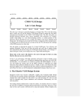
Introducton to CMOS VLSI Design (E158)
Lab 0: Gate Design
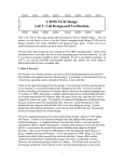
I. What is Electric
The Electric VLSI Design System is an open-source chip design program developed by
Steve Rubin support from Sun Microsystems. It is written in Java and hence will run on
virtually any operating system, including Windows, Linux, and Mac.
There are two general strategies for chip design. Custom design involves specifying how
every transistor is connected and physically arranged on the chip. Synthesized design
involves describing the function of a digital chip in a hardware description language such
as Verilog or VHDL, then using a computer-aided design tool to automatically generate a
set of gates that perform this function, place the gates on the chip, and route the wires to
connect the connect the gates. The majority of commercial designs are synthesized today
because synthesis takes less engineering time. However, custom design gives more
insight into how chips are built and into what to do when things go wrong. This tutorial
focuses on using Electric for custom design.
The main competing programs for custom chip design include Cadence, LASI, and
Tanner. Cadence is an industrial-strength suite that handles both custom and synthesized
designs. A complete package costs about $1 million / user and requires considerable
effort to install and maintain. Cadence does offers generous university discounts. The
Layout System for Individuals, LASI, developed by David Boyce, is freely available and
runs on Windows. It was last updated in 1998. Tanner offers another commercial
product that is significantly cheaper and easier to setup than Cadence. However, the
university pricing is similar to Cadence. All of these tools are used at universities around
the world. Electric is free, actively being improved, works on all platforms, and is
powerful enough to build multimillion-transistor custom chips, so we are pleased with it
for university educational and research use.
This series of tutorials teaches how to use Electric to design an integrated circuit. The
first step is to draw a schematic indicating the connection of transistors to build cells such
as NAND gates, NOR gates, and NOT gates. These cells are simulated by applying
digital inputs and checking that the outputs match expectation. A symbol for the cell is
also drawn. The next step is to draw a layout indicating how the transistors and wires are
physically arranged on the chip. The layout is checked to ensure it satisfies the design
rules and that the transistors match the schematic. Groups of cells are then combined to
1
create the core of the integrated circuit. The core is attached to a pad frame containing
connections to the external world.
II. Installing Electric
Electric is a Java program that can be freely downloaded from
staticfreesoft.com. We will use both Electric and the IRSIM simulator add-on,
which is more robust than the built-in ALS simulator.
This semester, we are using a special build of Electric 8.04 that incorporates IRSIM and
fixes an error related to “alternate contact design rules.” It is available on the class web
page and in the Charlie E158\8.04 directory. You can copy it to your own computer and
run it locally if you have Java installed.
III. Getting Started
To start Electric, simply double click on electricGNUIRSIM.jar.
All of your designs are stored in a library. Create a library by selecting File • New
Library. Name the library tutorial_xx, where xx are your initials. Save the library using
File • Save. Put it in your personal directory. The library will be saved in jelib (Java
Electric Library) format.
Electric occasionally crashes. Be sure to save often so that you do not lose too much
work. While Electric rarely corrupts libraries, it is wise to periodically create backups of
your libraries just in case.
IV. Schematic Entry
Our first step is to create a schematic for a 2-input NAND gate. Each gate or larger
component is called a cell. Cells have multiple views. For example, your NAND
schematic will be in the nand2{sch} view, while your layout will eventually go in the
nand2{lay} view and your AND gate will go in the and2{sch} view.
Choose Cell • New Cell. Name the cell nand2 and select the schematic view. The editor
window should have a heading tutorial_xx:nand2{sch} and the component panel on the
left will switch to schematic components.
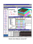
Your goal is to draw a gate like the one shown in Figure 1. Choose Windows • Toggle
Grid to turn on a grid to help you align objects. Left-click on an nMOS transistor symbol
in the components menu on the left side of the screen. Left-click on your schematic
window to drop the transistor into your layout. Repeat until you have two nMOS
transistors, two pMOS transistors, the circular power symbol, and the triangular ground
symbol arranged on the page. You may move the objects around by left-clicking and
dragging. The transistors default to a width/length value of 2/2. Double-click on all of the
transistors and change their widths to 12.
2
Figure 1: nand2{sch}
Now, make the connections. Left-click on a port such as the gate, source, or drain of a
transistor. Right-click on another port to create a wire connecting the ports. Continue
until all the blue wiring is completed.
Finally, you will need to provide exports defining inputs and outputs of the cell. Left
click on the end of a wire where you need to create the export for input a. You should see
a small square box highlighted at the end of the wire. If the entire wire is highlighted, you
clicked on the middle of the wire instead of the end, so try again. Once you have selected
the end of the wire, choose Export • Create Export. Give your export the name a. Give it
the characteristic Input. Repeat with the other input b. Export y as an Output.
Use File • Save (Ctrl-s) to save your library. Get into the habit of saving often because
Electric has been known to crash. Also, learn the keyboard shortcuts for the commands
you use frequently.
V. Simulation
Our next step is to simulate the schematic to ensure it is correct. Electric has two built-in
switch-level simulators: IRSIM and ALS. ALS is buggy, so we will use IRSIM. IRSIM
treats transistors as switches that may be ON or OFF; it also understands resistance and
capacitance based on transistor sizes and crudely estimates switching delays.
First select Tools • Simulation (Built-in) • IRSIM: Simulate Current Cell. You should see
the netlist being loaded in the messages window at the bottom of the screen. You will get
warnings that gnd and Gnd are being aliased, so that capitalization doesn’t matter. The
3
same goes for vdd and Vdd. You should see 6 nodes, 2 n-channel transistors, and 2 pchannel transistors in the circuit. The nodes are a, b, y, vdd, gnd, and the intermediate
node between the two series nMOS transistors.
A waveform window will appear listing each of the nets in your design. If you created
your exports properly, you will see nets for a, b, and y, as shown in Figure 2.
The simulator has two vertical dashed cursors. The primary cursor with long dashes used
to create stimulus. Click and drag the cursor near the left edge (near time 0). Click on the
a input in the simulation window and press g or choose Tools • Simulation (Built-in) •
Set Signal Low at Main Time to drive the input low. Click on the b input and press g
again. Drag the cursor to some later time. Click on the b input and press v to drive it high.
Sometime later, drive a high. Then a bit later, drive b back low, as shown in the figure.
Check that the y output matches the behavior you would expect for a NAND2 gate. If it
does not, fix the bug in your schematic and resimulate.
The secondary cursor with an x is only used to measure delays relative to the first cursor.
You will find that unloaded gate delays are under 100 ps. Gate delay depends on the
capacitance being driven, so attaching a realistic load will slow the gate.
Use the Windows • Adjust Position • Tile Vertically command to arrange the windows
so that you can see both the simulation window and your schematic at the same time.
Watch the color-coding of the wires in the schematic change as you drag the primary
cursor back and forth. On the schematic, green indicates high, blue indicates low, and
black indicates x, an illegal value. When a signal is selected in the waveform window, the
corresponding net will be highlighted on the schematic. Similarly, when a net is selected
in the schematic then its waveform representation will be highlighted. Watching the
voltage levels change on the schematic is helpful for debugging problems.
Figure 2: Simulation of nand2{sch}
4
Make a habit of simulating each cell after you draw it so you catch errors while the
design is fresh in your mind.
VI. Icon
Each schematic can have a corresponding symbol, called an icon, to represent the cell in
a higher-level schematic. You will need to create an icon for your 2-input NAND gate.
When creating your icon, it is a good idea to keep everything aligned to the grid, this will
make connecting icons simpler and cleaner when you need it for another cell.
While looking at your nand2{sch}, choose View • Make Icon. Electric will create a
generic icon based on the exports looking something like Figure 3. It will drop the icon
in the schematic for handy reference; drag the icon away from the transistors so it leaves
the schematic readable.
Figure 3: nand2{ic} from Make Icon
The Make Icon command is handy because it creates ports and also places a facet center
(a + symbol in the middle of the cell). The facet center is important for Electric tokeep
icons aligned to a grid and prevent nasty messes later on.
A schematic is easier to read when familiar icons are used instead of generic boxes.
Modify the icon to look like Figure 4. Pay attention to the dimensions of the icon; the
overall design will look more readable if icons are of consistent sizes.
Figure 4: nand2{ic} final version
5
Click on the icon and choose Cell • Down Hierarchy • Down Hierarchy to drop in to the
icon. The technology will automatically change to artwork so a palette will appear on the
left with various shapes. Click on the generic box and delete it but leave the input and
output lines. Turn on the grid.
The body of the NAND is formed from an open C-shaped polygon, a semicircle, and a
small circle. To form the semicircle, place an unfilled circle. Double-click to change its
size to 6x6 and to span only 180 degrees of the circle. Use the rotate commands under the
Edit menu to rotate the semicircle into place. Place another circle and adjust its size to
1x1. You will need to select Edit • Modes • Movement • Half Motion to move the circle
into place (because it should be centered on a half-grid location, then set alignment back
to Full Motion to restore grid alignment. Alternatively, you can press h and use the arrow
keys to move objects by ½ grid increments, then press f to return to full grid movement.
The opened-polygon shown in Figure 5 can be used to form the C-shaped body. Drop an
opened-polygon object. Select it and choose Edit • Modes • Edit • Toggle Outline Edit to
enter outline edit mode. (The ‘y’ key toggles in and out of outline edit mode). In this
mode, you can use the left button to select and move points and the right button to create
points. The delete key deletes points. Outline edit mode is not entirely intuitive at first,
but you will master it with practice. Choose Edit • Special Function • Exit Outline Edit
when you are done. If your shape is incorrect, delete it, drop another opened-polygon,
and try again.
Figure 5: Opened-Polygon
Electric is finicky about moving the lines with inputs or outputs. If you left-click and drag
to select the line along with the input, everything moves as expected. If you try to move
only the export name, it won’t move as you might expect. Therefore, make a habit of
moving both the line and export simultaneously when editing icons. Note that the line is
just an open-polygon and can be shortened if desired by entering Outline Edit mode.
Use the Text item in the artwork palette to place a label in the center of the icon. Doubleclick the label to change text to “nand2.”
VII. NOT Gate
Next, design a NOT gate. Name it inv. Draw the schematic and the icon, as shown in
Figure 6. Make the pMOS width 17 and the nMOS width 7. Simulate the gate to prove
that it works.
6
Figure 6: inv{sch} and {ic}
VIII. Hierarchical Design
A CMOS AND gate consists of a NAND gate followed by a NOT gate. The schematic is
constructed by connecting the icons for the two gates that you have already drawn. This
is an example of hierarchical design, reusing components that you have constructed
already.
Create a new schematic called and2{sch}. In the components palette on the left, click on
cell, then select nand2{ic}. Right click where you want to drop it on the schematic.
Repeat for the inv{ic}. Wire the two together and create exports on inputs a and b and
output y. Note that even though the labels already appear on the inputs and outputs, it is
necessary to reexport them so that they are accessible when you use the AND to build yet
larger cells. Double-click on the wire between the two gates and give it a name like yb so
you know what you are looking at in simulation. It is good practice to label every net in a
design if practical. When you are done, your and2 schematic should look like Figure 7.
Figure 7: and2{sch}
Simulate your and2 gate to ensure it works.
Make an icon for the and2. It should be similar to the nand2, but should leave off the
output bubble.
IX. Electric Manual
If you need more information at any point, bring up the user manual by selecting Help •
User’s Manual… Now that you know the basics, you will benefit from skimming
through the manual to learn the subtleties and find out the best way to do things. In
7
particular, look at Sections 1.6, 1.8, and 1.9 and Section 2. Make sure that you
understand nodes, arcs, and ports; that will help you understand why Electric does some
of the seemingly odd things that it does.
X. Manufacturing Processes
Before starting layout, you must choose the manufacturing technology in which your chip
will be built. In particular, Electric needs to know the feature size and design rules for
your technology. This tutorial will target the AMI 0.5 µm process using the MOSIS
scalable CMOS submicron design rules with λ = 0.3 µm. We choose this process
because MOSIS subsidizes fabrication costs for educational chips on this process. The
submicron scalable design rules allow the design to be ported to many other processes
without layout changes, and the rules have fewer idiosyncracies than the deep submicron
rules. Note that the minimum drawn transistor length is 2 λ = 0.6 µm. MOSIS
automatically scales polysilicon gates down by 0.1 µm before the chip is fabricated, so
the actual transistor length is 0.5 µm. The scalable SCMOS submicron rules are
illustrated on the inside back cover of CMOS VLSI Design. All dimensions are given in
lambda.
To set the technology, use File • Open Library to open your library from Part I of this
tutorial. Select File • Projects Settings. Click on the technology item on the left. Change
the Startup technology and Layout technology to use for Schematics to mocmos. Set the
number of metal layers to 3 and the Current foundary to MOSIS. Set the rules to
Submicron. Check Alternate Active and Poly contact rules, but not Second Polysilicon
Layer or Disallow Stacked Vias. Then click the Scale item on the left. Choose the
mocmos technology and set the Technology scale to 300 nm (0.3 microns).
By default, Electric creates transistors with horizontal polysilicon. We will use
transistors with vertical polysilicon. To avoid having to rotate all our transistors, choose
File • Preferences. In the Technology item of the Technology folder, check the “Rotate
transistors in menu” box. Electric also creates 3 l wide metal wires by default, while we
prefer 4 l wires. In the Arcs item of the General folder, select Technology of mocmos
and Arc Type of Metal-1. Set the default width to 4. Do the same for Metal-2. Set the
default width of Metal-3 to 6.
XI. Layout
To create a layout of a 2-input NAND gate, choose Cell • New Cell to bring up the New
Cell dialog. Enter nand2 as the name and layout as the view. You may also wish to
choose Cell • Edit Cell to open the nand2{sch}, then position the windows side-by-side
for easy reference.
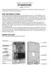
Your goal is to draw a layout exactly like the one shown in Figure 8. It is important to
choose a consistent layout style so that various cells can “snap together” like LEGOs.
Neatness and precision is imperative to get a good layout. In this project’s style, 8 λ-wide
power and ground wires run horizontally in metal1 at the top and bottom of the cell,
8
respectively. The spacing between power and ground is 90 λ center to center. nMOS
transistors occupy the bottom part of the cell and pMOS transistors occupy the top part.
Each cell has well and substrate contacts spaced 8 λ apart under the power and ground
wires. Inputs and outputs are placed on metal2 contacts. No other metal2 or metal3
should be used in the cells.
Figure 8: nand2{lay}
Start by drawing your nMOS transistors. Recall that an nMOS transistor is formed when
polysilicon crosses N-diffusion. N-diffusion is represented in Electric as green diffusion
surrounded by a dotted yellow N-select layer all within a hashed black P-well
background. This set of layers is conveniently provided as a 3-terminal transistor node in
Electric. Move the mouse to the components menu on the left side of the screen. As you
move the mouse over various objects, the node name will appear on the status line next to
the word NODE near the bottom left corner of the screen. Left click on the nMOS
transistor, and click again in the layout window to drop the transistor in place. There are
two nMOS transistors in series in a 2-input NAND gate, so we would like to make each
wider to compensate. Double-click on the transistor. In the node information dialog,
adjust the width to 12.
We need two transistors in series, so copy and paste the transistor you have drawn or use
the Edit • Duplicate command. Drag the two transistors along side each other so they are
not quite touching. Left click the diffusion (source/drain) of one of the transistors and
right click on the diffusion of the other transistor to connect the two. Then drag the two
transistors until the polysilicon gates are 3λ apart, looking like they do in Figure 8. You
will probably find it helpful to turn on the grid using the Window • Toggle Grid
command. The grid defaults to small dots every lambda and large dots every 10λ. By
default, objects snap to a 1-λ grid. This can be changed by using Edit • Modes •
Movement menu. You can also move objects around with the arrow keys on the
9
keyboard. Pressing the h or f keys cause the arrows to move objects by a half or full
lambda, respectively. You will avoid messy problems by keeping your layout on a
lambda grid.
Next we will create the contacts from the N-diffusion to metal1. Diffusion is also refered
to as active area. Drop a square of Metal-1-N-Active-Contact in the layout window and
double-click to change the properties to a Y size of 12. You will need a second contact
for the other end of the series stack of nMOS transistors, so duplicate the contact you
have drawn. Move the contacts near each end of the transistor stack and draw diffusion
lines to connect the transistors. Then move the contacts even closer; you only need a gap
of 1 λ between the metal and polysilicon. Using similar steps, draw two pMOS transistors
in parallel and create contacts from the P-diffusion to metal1. At this point, your layout
should look something like Figure 9:
Figure 9: Contacted transistors for nand2 layout
Run the design rule checker to see if your layout has any errors. Invoke it using Tools •
DRC • Check Hierarchically. The results are reported in the Electric Messages window.
If there are errors, use the > key to step through each one and highlight it on the layout.
Fix the errors and repeat until all errors are corrected.
Then add metal1 power and ground lines. The lines should be 8 lambda wide and 24
lambda long. You can add a line by selecting a pin such as metal-1-pin from the palette
then right-clicking nearby to draw the line. Double-click on the line to bring up the arc
properties and change the width to 8. Look for the facet center (a + symbol). Turn on the
grid. Drag the ground wire so that it starts 2 λ left of the facet center and it is vertically
centered on the facet center. Then move the power wire so it is 90 λ above the ground
wire. Click on the left node of the ground wire and export it as gnd with characteristic
ground. Similarly, export power as vdd with characteristic power.
To move the transistors into position near the power, left click and drag the mouse to
select all the nMOS transistors and contacts. Release the mouse, then hold the left mouse
10
button down again over the selected stuff to drag it. Move the transistors so the
polysilicon ends 1 λ above the ground wire. The leftmost contact should be 2 λ to the
right of the left edge of the ground wire.
Left-click on the leftmost active contact in the n-diffusion. Right-click on the ground
line. Electric will create a wire between the contact and ground. If the width comes up at
8 λ, double-click on the wire and change its width to 4 λ. Complete the other connections
to power and ground. When you are done, power and ground should extend 2 λ beyond
the contents of the cell (excluding wells) on either side so that cells may “snap together”
with their contents separated by 4 λ so design rules are satisfied.
Draw wires to connect the polysilicon gates, forming inputs a and b, and the metal1
output wire y.
You may find it helpful to zoom in and out to view the layout. There are several Zoom
commands under the Windows menu. Some have useful keyboard shortcuts.
If several pieces of layout are on top of each other, hold the control key and click several
times until the desired one is selected. When you are drawing a wire, if Electric
generates the wrong kind of layer (for example, diffusion instead of metal1), click on the
palette under the Pure column to choose a layer that Electric should use.
Recall that well contacts are required to keep the diodes between the wells and
source/drain diffusion reverse biased. We will place N-well and P-well contacts in each
cell under the power and ground wires every 8 λ. Drop 3 Metal1-N-Well-Con contacts
on the center of the power wire, starting 2 λ from the left edge. Click on each contact,
then click nearby on the power wire to form a connection. Repeat with P-well contacts on
the ground wire.
We will connect cells using vertical metal2 wires and horizontal metal3 wires. Metal2 is
drawn on an 8 λ grid (width = 4 λ, spacing = 4 λ). Metal3 is drawn on a 10 λ grid (width
= 6 λ, spacing = 4 λ). The metal2 wires will run in the same columns as the well and
substrate contacts, centered 2, 10, 18 λ, etc. right of the facet center. The metal3 wires
will run 0, 10, 20, 30, 50, 60, 70, 80, and 90 λ up from the facet center. Figure 10
illustrates the wiring grid. Inputs and outputs should be placed on metal1-metal2 contacts
called vias, centered on the metal2 columns (in the same column as the substrate
contacts). For example, a, b, and y are all on this grid.
11
90
80
70
Inputs and outputs
on metal1-metal2 contacts
centered on metal2
columns
60
40
30
20
10
0
2
10
18
Vertical metal2 on 8 λ grid
lined up with substrate contacts
Figure 10: Wiring grids and export locations
12
Horizontal metal3
on 10 λ grid
(multiples of 10)
50
For the output, create a metal1-metal2-con called a via. Connect it to the metal1 output
wire. Then select the via and create an export named y of type output. Create two more
vias for the two inputs. Place metal1-polysilicon1-con poly contacts two lambda away
from the vias. Connect the via to the contact and the contact to the polysilicon wires.
Export these as a and b. Note that a should connect to the leftmost transistor, just as it
connects to the bottom transistor in the schematic.
Electric is agnostic about the choice of well and substrate; it generates both n- and p-well
layers. In our process that has a p-substrate already, the p-well, indicated by black
slanting lines, will be ignored. The n-well, indicated by small black dots, will define the
well on the chip. Electric only generates enough well to surround the n and p diffusion
regions of the chip. It is a good idea to create rectangles of well to entirely cover each
cell so that when you abut multiple cells you don’t end up with awkward gaps between
wells that cause design rule errors. Electric uses pure layer nodes to create rectangles of
some layer. Choose from the Components palette Pure • N-Well-Node. Drop the small
rectangle of N-well on your layout. Pure layer nodes are hard to select in Electric. This
makes them difficult to accidentally select when you are editing something else. If you
need to select a hard-to-select object that is not already selected, click on the toolbar and
choose the arrow surrounded by blue, named “Toggle Special Select.” When it is
clicked, you can now select hard-to-select objects, but not normal objects. Click the
arrow again to return to normal selection mode.
Double-click on the N-Well pure layer node and change the width to 32 and the height to
56. Drag the layer over the pMOS transistors in your layout. It should extend 2 λ above
the power wire and fully cover all the other bits of N-well. Repeat the process with a PWell of width 32 and height 46 to cover the nMOS transistors, starting 2 λ below the
ground wire.
Sanity check your design. Double-check that everything is aligned to a 1 λ grid and that
the inputs and outputs are on the wiring grid. Exports should use all lower case letters.
Make sure you don’t have any 3 λ wide wires or any stray pins or other junk in the
layout.
Your design should now resemble Figure 8 and should pass DRC. Save the library.
XII. NCC and ERC
Electric has a powerful feature called Network Consistency Check (NCC) that compares
a layout and schematic to ensure they are identical. While looking at either the layout or
the schematic, choose Tools • NCC • Schematic and Layout Views of Cell in Current
Window.
13
If the layout and schematic match export names, transistor topology, and transistor sizes,
NCC will report success. If not, NCC will display information about the mismatches.
Tracking down the problem is an acquired skill.
Electric also has an electrical rule checker that ensures every well and substrate area has
at least one well or substrate contact. Choose Tools • ERC • Check Wells. The message
window should report that no errors were found.
XIII. Simulation
Simulate the nand2 layout. Apply all the possible inputs and verify that the correct
outputs are produced. If NCC passed, the simulation should work too.
XIV. Layout Templates
Recall that we want our cells to snap together easily. Therefore, all gates should be 90 λ
tall from the center of gnd to the center of VDD. The width of the gate depends on the
number of inputs. To match our routing grid, a logic gate is typically 8 λ wide for each
input or output.
Drawing the power and ground busses, pure layer nodes, and well and substrate contacts
is repetitive. Therefore, we will define layout templates that already have these
structures, along with some transistors and contacts. The templates are provided in
templates.elib.
To copy the templates into your library, open templates.elib. Choose Cell • Cross-Library
Copy… Select all four templates, 2col-5col. Copy them into your library. Then choose
File • Close Library to close templates.elib.
When you draw layouts, follow these guidelines:
•
•
•
•
Create the cell by choosing Cell • Duplicate. Choose one of the templates.
Duplicate it, giving it the name of the new cell that you want. For example, an
inverter has one input and one output. Thus, duplicate 2col and name it inv.
Place the nMOS transistors close to gnd and the pMOS transistors close to power
(ending 1 λ away from the wide wire). The largest transistors that can be drawn
are 27 λ for nMOS and 37 λ for pMOS.
Neatness counts. Pack transistors as close as possible to minimize stray
capacitance and resistance. Keep wires as short as possible.
Place vias for the inputs and outputs. The vias should fall on the routing grid.
There should never be more than one via in a column. If possible, the vias should
be on different rows.
XV. Hierarchical Design
14
To illustrate hierarchical layout, we will build an AND gate using a NAND and an
inverter. Figure 11 shows what the completed AND gate should look like.
Figure 11: and2{lay}
First, draw an inverter based on the 2col template. Be sure that the nMOS and pMOS
widths match the schematic. Check that it passes DRC and NCC.
Next, create a new cell layout for the and2. Click Cell in the components palette and
select nand2{lay}. Drop it on the layout. Repeat with inv{lay}. Select both cells (by
highlighting, shift-clicking, or using Edit • Select All). Choose Cell • Expand Cell
Instances • All The Way to see what is in the cells. Move the nand2 until its facet center
is aligned on top of the and2’s facet center. Move the inv until its power and ground
wires abut those of the nand. The arrow keys are helpful to do this movement.
15
Connect the output of the nand2 to the input of the inverter using metal1. Also connect
the power and ground wires of the two cells using metal1. (Remember that even though
they appear to touch, Electric only understands that they should be connected if you
explicitly draw an arc between them). Export the a and b inputs of the nand and the y
output of the inverter as the new inputs and output of the and. Also export vdd and gnd.
Check your design with DRC and NCC and fix any errors.
XVI. For More Practice
Design schematics, icons, and layouts for the following two gates. Simulate the gates to
prove that they work correctly. Check DRC, ERC, and NCC.
•
•
2-input NOR gate: nor2 (use transistor widths of 8 for the nMOS and 16 for the
pMOS)
2-input OR gate: or2 (using a NOR and a NOT gate)
XVII. What to Turn In
Please provide a hard copy of each of the following items. Before printing, choose
Window • Color Schemes • White Background Color to change the background color so
the printout is more readable and you don’t use so much toner. Unfortunately, Electric
has no graceful way to cut and paste layouts or schematics into documents. You can
either print directly or press the Print Screen button, then paste the screen shot into a
paint program and crop and paste that into a word processor.
1. Please indicate how many hours you spent on this lab. This will not affect your grade,
but will be helpful for calibrating the workload for the future.
2. A printout of your nor2 schematic.
3. A printout of your nor2 layout.
4. A printout of your or2 schematic.
5. A printout of your or2 layout.
6. Simulation waveforms demonstrating correct operation of the or2 layout.
7. What is the verification status of your or2 layout? Does it pass DRC? ERC? NCC?
16