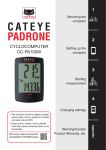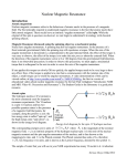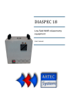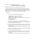
1
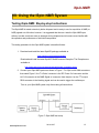
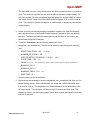
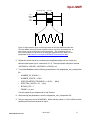
iSpin-NMR™
Owner’s Manual
SpinCore Technologies, Inc.
http://www.spincore.com
iSpin-NMR
Congratulations and thank you for choosing a design from
SpinCore Technologies, Inc.
We appreciate your business!
At SpinCore we try to fully support the needs of our customers. If you
are in need of assistance, please contact us and we will strive to provide
the necessary support.
© 2007 - 2014 SpinCore Technologies, Inc. All rights reserved.
SpinCore Technologies, Inc. reserves the right to make changes to the product(s) or information herein without notice.
RadioProcessor™, iSpin-NMR™, PulseBlaster™, SpinCore, and the SpinCore Technologies, Inc. logos are trademarks of SpinCore
Technologies, Inc. All other trademarks are the property of their respective owners.
SpinCore Technologies, Inc. makes every effort to verify the correct operation of the equipment. This equipment version is not intended
for use in a system in which the failure of a SpinCore device will threaten the safety of equipment or person(s).
www.spincore.com
2014-10-27
2
iSpin-NMR
Table of Contents
I. Introduction.................................................................................................. 5
II. Product Overview ....................................................................................... 6
III. Typical Application.................................................................................... 7
IV. General Operation Description................................................................ 8
V. Inside the iSpin-NMR.................................................................................. 9
VI. Connector Information............................................................................ 12
RF Connectors.................................................................................................................. 13
Digital (TTL) Connector..................................................................................................... 13
USB Connector................................................................................................................. 14
Hardware Reset/Trigger Connectors................................................................................. 14
VII. Using the iSpin-NMR System................................................................ 15
Testing iSpin-NMR: Step-by-step Instructions..................................................................... 15
Conducting an NMR Experiment with the iSpin-NMR: Step-by-step Instructions ...........19
VIII. MATLAB GUI Interface.......................................................................... 21
Overview of SpinCore MATLAB GUI Interface..................................................................... 21
General Features:............................................................................................................. 21
Sample Screenshots......................................................................................................... 22
IX. LabVIEW NMR Interface.......................................................................... 25
Overview of SpinCore LabVIEW GUI Interface..................................................................... 25
X. Pre-amplifier Filter Selection Considerations ........................................27
XI. Power Amplifier Precautions.................................................................. 28
Connecting & Disconnecting Power Amplifiers.................................................................. 28
Power Considerations....................................................................................................... 28
XII. Related Products and Accessories....................................................... 29
XIV. Contact Information.............................................................................. 30
www.spincore.com
2014-10-27
3
iSpin-NMR
XV. Document Information........................................................................... 30
www.spincore.com
2014-10-27
4
iSpin-NMR
I. Introduction
The iSpin-NMRTM is SpinCore's Portable Broadband NMR system. Built around the
RadioProcessor board and SpinCore's NMR software, once connected to a probe the iSpin-NMR is
instantly ready to perform NMR experiments from 0 to 100 MHz and beyond! *
This manual provides all the information you need to get started with your iSpin-NMR system, and
includes sections on typical applications with connection diagrams, detailed descriptions of the
iSpin-NMR's internal components, connector information, testing and experiment procedures and
more.
For more details about technical information pertaining to SpinCore's RadioProcessor board – the
primary component of the iSpin-NMR system, responsible for all digital control and signal
processing – or information about writing your own pulse programs and experiments, the user is
encouraged to also read the SpinCore RadioProcessor user manual which can be found at the
following location:
http://www.spincore.com/CD/RadioProcessor/RadioProcessor_manual.pdf
Should you have any questions that are not answered in either manual, please contact SpinCore
Technologies, Inc. using the contact information section at the end of this document.
Thank you for choosing SpinCore Technologies, Inc. for your mobile NMR needs, and be sure to
visit www.spincore.com for the latest information about SpinCore's products!
*
Certain limitations apply, vide infra.
www.spincore.com
2014-10-27
5
iSpin-NMR
II. Product Overview
The block diagram of the iSpin-NMR system is presented in Figure 1. The iSpin-NMR system
console contains SpinCore's USB RadioProcessor board (Item #1), broadband power amplification
unit (Item #2), and broadband pre-amplification unit (Item #3). The iSpin-NMR generates a NMR
excitation pulse, amplifies that pulse, and then acquires data from a probe, performing digital
detection, filtering and signal averaging autonomously. It connects to any PC or laptop via USB
2.0.
Figure 1: iSpin-NMR system block diagram.
The iSpin-NMR system console is equipped with a universal AC input power supply (90 to 240
VAC) and consumes no more than 80 Watts. The power supply inside the iSpin-NMR console
complies with CE, UL, CSA, and TUV. The metal enclosure meets FCC/FTZ regulations. The
iSpin-NMR system console is RoHS compliant and is intended for operation at room temperature,
typically in the range of temperatures from 15° C to 28° C, with a relative humidity limit of 35%70% (non-condensing), no visible moisture, and at altitudes not exceeding 5 km.
www.spincore.com
2014-10-27
6
iSpin-NMR
III. Typical Application
The iSpin-NMR is typically used for Nuclear Magnetic Resonance (NMR), Nuclear Quadrupole
Resonance (NQR) and Magnetic Resonance Imaging (MRI) applications. The typical connection
diagram for those applications is depicted below in Figure 2
Figure 2: iSpin-NMR Connection Diagram for typical applications. On some systems, the Duplexer, or some of
its parts, may be installed inside the iSpin-NMR system.
The sample being studied is placed in the RF coil (antenna) of the probe. The probe is connected
to the iSpin-NMR system via the fast Transmit/Receive switch, comprised of appropriate RF coaxial
cables and fast switching diodes.
The diodes and the λ/4 cable protect the receiver of the iSpin-NMR system when excitation pulses
are applied, while facilitating the isolation of the transmitter's circuitry from the receiver when
acquiring the small-signal response from the sample.
NOTE: The iSpin-NMR system is available in an alternative output configuration. This alternative
output configuration has the switching diodes embedded within the enclosure, thus eliminating the
need for a Tx cable.
www.spincore.com
2014-10-27
7
iSpin-NMR
IV. General Operation Description
The iSpin-NMR is designed to be simple, intuitive and effective. The following is an outline of how
the iSpin-NMR operates for typical NMR/NQR experiments.
1. The user inputs the necessary parameters into SpinCore's NMR GUI or alternative
software program.
2. When the user begins the scan, the iSpin-NMR generates the NMR excitation pulses
depending on the input parameters.
3. During specific intervals in the pulse sequence (typically after the excitation pulse in a
single-pulse NMR experiment), the system will acquire the data returned from the
sample in the sample probe. The iSpin-NMR system digitizes the signal and performs
digital detection, filtering, and autonomous signal averaging. The processed digital
values are stored on the iSpin-NMR console and are available for download to the host
computer at the user's convenience.
4. Transmit/Receive Circuitry (sold as a separate component) will automatically switch
between the excitation pulses and the signal input from the probe. The input signal from
the sample probe is passed through a lambda-quarter cable (part of the
Transmit/Receive switching circuit), fed into a pre-amplifier inside the iSpin-NMR
system, and then follows to the digital receiver on the RadioProcessor board inside the
iSpin-NMR system for digitization and digital signal processing.
5. The system continues to scan the specified number of times, automatically averaging
the values stored on chip for each scan. Data may be downloaded to the host computer
at any time for inspection, visualization, and processing, without interfering with the
ongoing data acquisition. The user can download the data received from the
RadioProcessor using SpinCore's NMR GUI, SpinCore's non-GUI C/C++ program, or
alternative software tools.
6. NMR/NQR data are saved on the host computer in three different formats, including
ASCII (plain text file) and JCAMP-DX, for post-acquisition processing, visualization, and
analysis.
For a more detailed description of iSpin-NMR operation, please consult section VII, “Using the
iSpin-NMR System,” in this manual.
www.spincore.com
2014-10-27
8
iSpin-NMR
V. Inside the iSpin-NMR
A photograph of the internal components of the iSpin-NMR system is shown below in Figure 3. For
descriptions of each component see the following page.
Figure 3: Inside the iSpin-NMR system.
www.spincore.com
2014-10-27
9
iSpin-NMR
1. USB RadioProcessor Board: The heart of the iSpin-NMR system. The
RadioProcessor board generates the completely formed excitation signals and then
captures and digitally processes the NMR signals. Digital detection, filtering, and
autonomous signal averaging are standard features, as well as shaped excitation
pulses. For more information on RadioProcessor, including performance characteristics
from 0 to 100 MHz, please visit the URL
http://www.spincore.com/products/RadioProcessor/.
The RF output of the RadioProcessor is connected to the Power Amplifier module, and
the RF input is connected directly to the output of the small-signal preamplifier and filter.
2. Power Amplifier: Used to amplify the NMR excitation pulses. The supplied Power
Amplifier is broadband, and is able to supply continuous power at the desired frequency
of operation. There are several available power amplifiers: the PA10W, capable of
supplying 20 Watts Peak Envelope Power, the PA15W, capable of supplying 30 Watts
Peak Envelope Power, and the PA75W, capable of supplying 150 Watts Peak Envelope
Power. For more information, please visit http://spincore.com/products/RFPA/. If higher
power is needed, a final Power Amplifier stage can be provided with output power
ranging from 100 to 1000 Watts. Please contact SpinCore for more details.
3. Preamplifiers and filters: The supplied preamplifiers are broadband, 1-200 MHz, and
provide ~60 dB gain.. The preamplifiers are supplemented with band-pass (or low-pass)
filters. When ordering, please specify your frequency of interest for the selection of
appropriate filters.
4. Input and output RF connectors: BNC Connectors are used for RF signals,
connecting with the Transmit/Receive Circuitry. NOTE: Systems that have internal
switching diodes will have three SMA connectors instead of two BNC connectors. More
information about these connectors can be found in the RF Connectors section on the
following page. An additional DB-9 type connector is used to output TTL signals for
multi-system synchronization or control of any required peripheral devices.
5. Universal AC Power Supply: Accepts 90-240 V AC power, 50 - 60 Hz. A standard PC
power cable can be used. No warm-up time needed/present, a sub-second power-on,
no user-serviceable fuse, internally protected, will shut-off when overloaded. Note: The
iSpin-NMR system contains a mechanical “Power On” switch that can be in two
positions: “On” or “Off.” If the unit is presently powered with the switch in the “On”
position, then it will power on again without manual intervention when the AC power
mains is cycled off then on.
www.spincore.com
2014-10-27
10
iSpin-NMR
6. USB 2.0 Interface: Contains the USB 2.0 interface hardware and software.
7. Large-diameter fan: Included for efficient heat dissipation and quiet operation.
8. Ample space inside: There is plenty of room inside the iSpin-NMR console for an
embedded computer, small permanent magnet, or touch screen, if desired.
www.spincore.com
2014-10-27
11
iSpin-NMR
VI. Connector Information
This section provides descriptions of the external connectors for the iSpin-NMR. Figure 4, below,
shows a sketch of the front and back panels of the iSpin-NMR system.
Figure 4: Front (left) and back (right) sides of the iSpin-NMR (dimensions are in mm). The size of the
enclosure is 180mm x 165mm x 340 mm. The large circles on the back panel represent the fan's exhaust.
This exhaust port should not be blocked or covered.
www.spincore.com
2014-10-27
12
iSpin-NMR
RF Connectors
The standard system has two standard BNC jack (female) connectors that allow for the iSpin-NMR
system to be easily connected to via standard BNC cables. These two RF BNC connectors are
labeled “RF Power Out” and “NMR Signal In.”
NOTE: For systems shipped with the internal switching diodes there are three SMA jack (female)
connectors. These three SMA connectors can be easily connected to via standard SMA cables.
Two of the SMA connectors are labeled “λ/4 Cable” and the third connector is labeled “To Probe.”
The left “λ/4” connector corresponds to the “NMR Signal In” and the “To Probe” corresponds to the
“RF Power Out”. Please see the below figure for an example of the connector layout.
Figure 5: Connector layout for an iSpin with internal diodes. The
circles in this figure represent SMA connectors.
CAUTION: Output voltages can reach values greater than 200 V peak-to-peak and can be
fatal.
CAUTION:A 50 Ω load needs to be present at the “RF Power Out” or “To Probe” connector
at all times.
Digital (TTL) Connector
The digital, TTL-compatible, outputs of the iSpin-NMR are present on the bracket-mounted DB-9
(female) connector marked TTL. The pinout of this connector and the corresponding signal names
are shown below in Figure 6. The maximum drive capability in the logical “1” is 15 mA. The
maximum sinking current for a logical “0” is 15 mA. NOTE: TTL signal “Bit 2” is often connected
internally with the input pin of the power amplifier unit.
Figure 6: TTL Output Connector (DB9-female) and signal list.
www.spincore.com
2014-10-27
13
iSpin-NMR
USB Connector
The USB connector is a USB Type-B connector, and can easily be connected to a computer via a
standard USB 2.0 cable.
Hardware Reset/Trigger Connectors
Access to the hardware reset and hardware trigger lines of the RadioProcessor USB is provided via
RCA jacks labeled “Reset” and “Trigger”. For more information about the function of these pins,
please see the SpinCore RadioProcessor manual.
www.spincore.com
2014-10-27
14
iSpin-NMR
VII. Using the iSpin-NMR System
Testing iSpin-NMR: Step-by-step Instructions
The iSpin-NMR is tested extensively before shipment and is ready to use for acquisition of NMR (or
NQR) signals out-of-the-box, however, it is suggested that the user tests the iSpin-NMR upon
delivery to make sure there were no damages during shipment and to become more familiar with
the operation and performance of individual components.
The testing procedure for the iSpin-NMR system is described below:
1. Download and install the latest SpinAPI package available at:
http://spincore.com/support/spinapi/
Download and install the latest SpinAPI RadioProcessor Examples. The Examples are
available at:
http://www.spincore.com/support/spinapi/spinapi_examples.shtml
2. Connect your iSpin-NMR system as shown in Figure 7. For iSpin's with SMA connectors
that match Figure 5, the 'To Probe' connector is the 'RF Power Out' connector and the
left 'λ/4' connector is the 'NMR Signal In' connector. Note that pin-4 on the TTL output
DB-9 connector is the blanking signal and can be used to trigger the oscilloscope.
Turn on your iSpin-NMR system only after making all connections.
Figure 7: iSpin-NMR test setup.
www.spincore.com
2014-10-27
15
iSpin-NMR
The iSpin-NMR receiver is very sensitive and can detect signals less than 1 μV peak-topeak. The maximum input that can be received without distortion is approximately 2.5
mV peak-to-peak. Be sure to attenuate the signal going into the iSpin-NMR so it falls in
this range. The RF output of the iSpin-NMR can be as high as 75 W, or 200 V peak-topeak. This voltage is typically too large for an oscilloscope, so be sure to attenuate the
output properly.
3. Create your own new working directory somewhere outside of the SpinCore directory
and copy the contents of the SpinAPI RadioProcessor Examples to your new working
directory. The SpinCore RadioProcessor directory can be found in the location you
downloaded the SpinAPI Examples.
4. To test the Transmitter, edit the following parameters in the
singlepulse_nmr_example.bat. This file can be edited by right-clicking and selecting
“edit.”
•
REPETITION_DELAY = 0.5
•
NUMBER_OF_SCANS = 100
•
SPECTROMETER_FREQUENCY = 20.001
•
PULSE_TIME = 10.0
•
FNAME = tx_test
•
BLANKING_EN = 1
•
BLANKING_BIT = 2
•
BLANKING_DELAY = 3.0
•
AMPLITUDE = 0.1
(seconds)
(MHz)
(μs)
(the output files can be ignored when only testing the transmitter)
(ms)
All other values can be left as default.
5. After entering the parameters, save the singlepulse_nmr_example.bat file, then run it by
double-clicking the file. On the oscilloscope you should see a 20.001 MHz sine wave
that is on for 10.0 μs. The amplitude of the sinusoid depends on the attenuation of the
RF output signal. This will repeat 100 times every 0.5 seconds and then stop. The
diagram in Figure 8, on the following page, shows what a typical oscilloscope output will
look like for this test.
www.spincore.com
2014-10-27
16
iSpin-NMR
De-blanking Delay
Pulse Time
Deblanking
Signal
RF
Output
Figure 8: Representation of the oscilloscope output for the iSpin-NMR transmitter test.
The iSpin-NMR's internal RF power amplifiers requires a specific de-blanking time, for
each model, prior to the RF pulse for full output power . The de-blanking time for
each power amplifier can be found in the RF power amplifier manuals, which can be
downloaded at http://spincore.com/products/RFPA/RF-Power-Amplifier.shtml.
6. Repeat this test a few times, increasing the amplitude setting until you reach your
desired output power (up to a maximum of 1.0). The output power should not exceed
10W RMS for a PA10W, 15W RMS for a PA15W, etc.
7. To test the Receiver, edit the following parameters in the singlepulse_nmr_example.bat
file:
•
NUMBER_OF_SCANS = 1
•
NUMBER_POINTS = 16384
•
SPECTROMETER_FREQUENCY = 20.001
•
SPECTRAL_WIDTH = 50
•
BYPASS_FIR = 1
•
FNAME = rx_test
(MHz)
(kHz)
Use the amplitude you determined in step 5 above.
8. After entering the parameters, save the singlepulse_nmr_example.bat file.
9. Set your frequency source 20.000 MHz. Notice that this value is 1.0 kHz offset from the
spectrometer frequency entered in step 6.
www.spincore.com
2014-10-27
17
iSpin-NMR
10. Run the singlepulse_nmr_example.bat by double-clicking the file. After the scan has
completed, the program will generate three output files (rx_test.fid, rx_test.jdx, and
rx_test.txt).
11. Open the “rx_test.fid” file using Felix NMR software (available for 32-bit Windows
systems, available for download at:
http://www.spincore.com/support/RadioProcessor/Felix/Felix_Instructions.shtml) and
verify the 1 kHz signal. After doing the FFT, you should see a strong signal at 1 kHz.
Figure 9 shows data captured by the iSpin-NMR system with a signal attenuated by over
100 dB. The time domain signal is on top (expanded) and the FFT is shown on the
bottom.
Figure 9: Data received by an iSpin-NMR system performing the Rx test. The
input signal is attenuated by over 100 dB and is less than 18 μV peak-to-peak.
www.spincore.com
2014-10-27
18
iSpin-NMR
Conducting an NMR Experiment with the iSpin-NMR: Step-bystep Instructions
1. Download and install the latest SpinAPI package available at:
http://spincore.com/support/spinapi/
Download and install the latest SpinAPI RadioProcessor Examples. The Examples are
available at:
http://www.spincore.com/support/spinapi/spinapi_examples.shtml
2. Connect your iSpin-NMR system as shown in Figure 2 (page 7).
3. Check all connections and then power on your system. WARNING: A 50 Ohm load
MUST be presented to the “RF Power Out” connector of the iSpin-NMR system. If
no load/probe is connected, or if probe is not properly matched/tuned, you may
damage the system. For iSpin devices with SMA connectors that match Figure 5,
the “To Probe” connector corresponds to the “RF Power Out”. If you have any
questions, PLEASE contact us.
4. Create your own new working directory somewhere outside of the SpinCore directory
and copy the contents of the SpinAPI RadioProcessor Examples to your new working
directory. The SpinCore RadioProcessor directory can be found in the location you
downloaded the SpinAPI Examples.
5. Edit the singlepulse_nmr_example.bat batch file by right-clicking and selecting “edit” and
save the batch file when finished. The timing values in the batch file correspond to
those in Figure 10, on the following page.
6. Run the singlepulse_nmr_example.bat file by double-clicking. Once the
singlepulse_nmr.bat file has completed, three new files (*.fid, *.jdx, *.txt) will be created
in the directory from which the batch file was executed.
www.spincore.com
2014-10-27
19
iSpin-NMR
DeBlanking
Signal
RF
Output
NMR
Signal
De-blanking Delay Pulse Time
Transient
Time
Acquisition Time
Repetition Delay
Figure 10: Timing diagram for one single pulse NMR scan (not drawn to scale).
7. Load the Felix file (.fid) in Felix for Windows, or load the .jdx file in any program that
supports JCAMP-DX. An easily parsed text file containing the NMR data will also be
generated. For information on installing and using Felix to view your .fid files, go to
http://www.spincore.com/CD/RadioProcessor/felix/Felix_Instructions.html
The NMR data received should look something like that of the screenshots shown in sections VIII
and IX. For information about about specific control signals for NMR tests which would allow for
custom NMR experiments, see the SpinCore RadioProcessor manual at
http://www.spincore.com/CD/RadioProcessor/RadioProcessor_manual.pdf
www.spincore.com
2014-10-27
20
iSpin-NMR
VIII. MATLAB GUI Interface
Overview of SpinCore MATLAB GUI Interface
The SpinCore MATLAB GUI Interface is a series of programs created for the MATLAB environment
that allows quick and easy interaction with the iSpin-NMR system. Specifically, this interface is
designed to allow users to perform a variety of useful experiments with their system. Complete
documentation for the SpinCore MATLAB GUI can be found here:
http://www.spincore.com/support/RadioProcessor/MATLAB/Documentation.html
General Features:
•
Run NMR experiments with ease, including Single Pulse, CPMG, and 90 Degree PulseWidth Determination
•
Change experiment parameters quickly and easily
•
Preview data in MATLAB immediately after the scan
•
Combine the versatility of the RadioProcessor with the power of the MATLAB environment
•
Quickly find resonant spectrometer frequency through automatic detection
•
90 Degree Pulse-Width Finder allows quick and simple detection of important pulse width
parameters
•
CPMG NMR now includes a feature to calculate T2 relaxation times for samples with a single
exponential
•
Continuous Scan setting for Single Pulse NMR
•
Load and review data from previous Single Pulse NMR experiments within the interface.
Note: Versions prior to R5 do not have support for iSpin-NMR systems. Versions after R8g have
full functionality for the iSpin-NMR for every function.
www.spincore.com
2014-10-27
21
iSpin-NMR
Sample Screenshots
Figure 11: Sample output after running Single Pulse NMR experiment on household
cooking oil.
Figure 12: Output as above, displaying Magnitude plot and Semi-log FFT.
www.spincore.com
2014-10-27
22
iSpin-NMR
Figure 13: Sample output after running CPMG NMR experiment on household cooking oil.
Figure 14: Sample T2 calculation and curve fitting.
www.spincore.com
2014-10-27
23
iSpin-NMR
Figure 15: Automatic 90 Degree Pulse Width Determination.
www.spincore.com
2014-10-27
24
iSpin-NMR
IX. LabVIEW NMR Interface
Overview of SpinCore LabVIEW GUI Interface
SpinCore has developed an easy-to-use LabVIEW Graphical User Interface (GUI) that combines
the Single Pulse NMR, T1 Inversion Recovery, and CPMG interfaces into one interface. It allows
the user to run basic NMR experiments by simply setting the experiment parameters as described
elsewhere in this manual. Extra features in LabVIEW GUI include lightning fast resonance finder,
built-in FFT and phasing, CYCLOPS phase cycling experiments, 90 degree pulse width finder, and
continuous scan mode. The following two figures are screenchots of the LabVIEW NMR Inferface.
For more information see the LabVIEW manual at:
http://www.spincore.com/support/PBLV/PBLV_RP_NMRinterface_Manual.pdf
NOTE: A National Instruments license is not required to run the LabVIEW interface.
Figure 16: Example of RadioProcessor LabVIEW Extensions User Interface.
www.spincore.com
2014-10-27
25
iSpin-NMR
Figure 17: Example of Pulse Width Finder for LabVIEW NMR Interface.
www.spincore.com
2014-10-27
26
iSpin-NMR
X. Pre-amplifier Filter Selection
Considerations
The iSpin-NMR receiver is very sensitive to small signals and has a broad input frequency range for
maximum versatility. While this feature can be very useful, the broadband receiver may capture
unwanted noise if not used correctly. At SpinCore we customize your iSpin-NMR system to your
specific operating frequency and can provide custom band-pass filters at those specific
frequencies. Contact SpinCore Technologies for more information.
Figure 18, on the following page, shows the iSpin-NMR receiver sensitivity when connected to a 72
MHz RF signal that is attenuated by 120 dB down to less than 1.8 μV peak-to-peak. The left side
shows received data using a 98 MHz low-pass filter, and the right side shows received data when
using a 72 MHz band-pass filter. The performance benefits of the band-pass filter are clear.
Figure 18: iSpin-NMR Receiver performance using low-pass filters (left) and band-pass filters (right).
www.spincore.com
2014-10-27
27
iSpin-NMR
XI. Power Amplifier Precautions
Working with RF power amplifiers can be dangerous and even fatal if not handled properly. All
precautions should be taken while operating the iSpin-NMR as an RF power amplifier is used in its
operation. Output voltages can reach values greater than 100 V peak-to-peak and can be fatal.
Follow these steps to avoid damaging the amplifier or inflicting serious injuries.
Connecting & Disconnecting Power Amplifiers
When connecting the power amplifier, follow these steps to avoid damaging the amplifier or
inflicting serious injuries.
1) Apply the load to the amplifier (make sure a load is ALWAYS present when working with
power amplifiers).
2) Apply the DC power to the amplifier.
3) Apply the RF input to the amplifier.
Repeat the steps in reverse order when disconnecting the amplifier.
Power Considerations
Make sure the following considerations have been made before applying power to the amplifier.
1) Be sure your load can appropriately dissipate the maximum power being applied by the
amplifier.
2) When applying an RF signal, work with low duty cycles to limit the power being
dissipated. The duty cycle ratio should be below 1% for safe operation.
www.spincore.com
2014-10-27
28
iSpin-NMR
XII. Related Products and Accessories
1. RadioProcessor: Complete RF Acquisition and Excitation System with Digital Detection,
Real-Time Signal Processing and Signal Averaging. For more information, please visit
http://spincore.com/products/RadioProcessor/
2. RF Power Amplifiers PA10W, PA15W, PA75W and PA100W. For more information,
please visit http://spincore.com/products/RFPA/
3. PulseBlaster: Programmable TTL Pulse Generator / Digital Word Generator and Timing
Engine. For more information, please visit http://spincore.com/products/PulseBlaster/
4. SpinCore also offers the following to supplement the iSpin-NMR system.
•
NMR Magnets
•
Probes
•
Duplexer (Transmit/Receive) Circuitry.
•
Custom RF Filters and Cables.
•
iSpin-NMR in Rack Mount Enclosure.
•
Oven controlled oscillators with sub-ppm stability.
5. All components of the iSpin-NMR system may be ordered separately. For custom
designs, modifications or software development, please inquire with SpinCore Technologies
through our contact form, which is available at http://spincore.com/contact.shtml.
6. The iSpin-NMR system can also be delivered in a 2U Rackmount enclosure (see photo
below). The size of this enclosure is 482.6 mm x 279.4 mm x 88.9 mm (Width x Depth x
Height).
www.spincore.com
2014-10-27
29
iSpin-NMR
XIII. Contact Information
SpinCore Technologies, Inc.
4631 NW 53rd Avenue, SUITE 103
Gainesville, FL 32653
USA
Telephone (USA):
Fax (USA):
352-271-7383
352-371-8679
Website:
Web Contact Form:
http://www.spincore.com
http://www.spincore.com/contact.shtml
XIV. Document Information
Revision History available at SpinCore.
www.spincore.com
2014-10-27
30