1
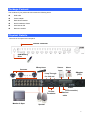
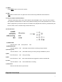
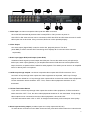
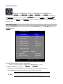
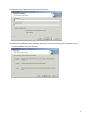
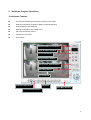
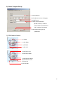
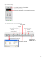
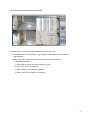
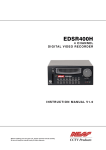
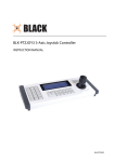
Triplex Digital Video Recorder
DVR-1650
User’s manual
1
Copyright
Copyright (C) 2005 PLANET Technology Corp. All rights reserved.
The products and programs described in this User’s Manual are licensed products of PLANET Technology, This User’s
Manual contains proprietary information protected by copyright, and this User’s Manual and all accompanying hardware,
software, and documentation are copyrighted.
No part of this User’s Manual may be copied, photocopied, reproduced, translated, or reduced to any electronic medium
or machine-readable form by any means by electronic or mechanical. Including photocopying, recording, or information
storage and retrieval systems, for any purpose other than the purchaser's personal use, and without the prior express
written permission of PLANET Technology.
Disclaimer
PLANET Technology does not warrant that the hardware will work properly in all environments and applications, and
makes no warranty and representation, either implied or expressed, with respect to the quality, performance,
merchantability, or fitness for a particular purpose.
PLANET has made every effort to ensure that this User’s Manual is accurate; PLANET disclaims liability for any
inaccuracies or omissions that may have occurred.
Information in this User’s Manual is subject to change without notice and does not represent a commitment on the part of
PLANET. PLANET assumes no responsibility for any inaccuracies that may be contained in this User’s Manual. PLANET
makes no commitment to update or keep current the information in this User’s Manual, and reserves the right to make
improvements to this User’s Manual and/or to the products described in this User’s Manual, at any time without notice.
If you find information in this manual that is incorrect, misleading, or incomplete, we would appreciate your comments and
suggestions.
CE mark Warning
The is a class B device, In a domestic environment, this product may cause radio interference, in which case the user may
be required to take adequate measures.
WEEE Warning
To avoid the potential effects on the environment and human health as a result of the presence of hazardous
substances in electrical and electronic equipment, end users of electrical and electronic equipment should
understand the meaning of the crossed-out wheeled bin symbol. Do not dispose of WEEE as unsorted
municipal waste and have to collect such WEEE separately.
Trademarks
The PLANET logo is a trademark of PLANET Technology. This documentation may refer to numerous hardware and
software products by their trade names. In most, if not all cases, their respective companies claim these designations as
trademarks or registered trademarks.
Revision
User’s Manual for PLANET Triplex Digital Video Recorder
Model: DVR-1650
Rev: 1.0 (Oct. 2005)
Part No. EM-DVR1650V1
2
Table of Contents
Chapter 1 Introduction .................................................................................... 1
Overview .......................................................................................................................1
DVR Functions................................................................................................................ 1
Package Content ..........................................................................................................2
Physical Details............................................................................................................2
Buttons Definitions.......................................................................................................... 3
Physical Interfaces........................................................................................................... 5
Chapter 2 DVR- 1650 Menu Setup ................................................................ 10
Introduction ................................................................................................................10
Menu Tree ......................................................................................................................11
MAIN MENU ............................................................................................................... 12
SYSTEM SETUP.......................................................................................................... 13
DISPLAY SETUP ......................................................................................................... 16
RECORDING SETUP................................................................................................... 18
ALARM SETUP ........................................................................................................... 19
MOTION SETUP.......................................................................................................... 21
WEEKLY SCHEDULE ................................................................................................. 23
NETWORK SETUP...................................................................................................... 25
ARCHIVING ................................................................................................................ 27
Playback archived video files ........................................................................................ 28
HDD INFORMATION .................................................................................................. 30
PLAYBACK Configurations .......................................................................................32
Search List .................................................................................................................... 32
Display mode..............................................................................................................34
Recording mode.........................................................................................................36
Playback mode...........................................................................................................37
PTZ control Procedure ..............................................................................................38
Chapter 3 Utility Administration ................................................................... 39
NetViewer utility .........................................................................................................39
Procedures of DVR Client utility................................................................................... 39
Appendix A Pin Description of connectors................................................. 63
Appendix B Software Upgrade Procedure .................................................. 65
Appendix C Specification.............................................................................. 68
3
Chapter 1
Introduction
1
Overview
The DVR-1650 (Triplex Digital Video Recorder) is for recording/playback/Network video streams from up to 16
channels at the same time. It adopts cutting-edge digital image compression technology to compress the
analog input channel video streams, and uses HDD to record the compressed video stream.
The following operation guide explains how to operate/manage the DVR-1650, and the following installation
guide explains how to complete the first DVR-1650 installation on your side.
DVR Functions
This DVR provides recording capabilities for 16 camera inputs. It provides playback or live display and
network function while in recording mode. And it also offers the following features:
• Real-time recording for up to 16 analog cameras, maximum up to 60 NTSC IPS (Image per second),
50 PAL Images per Second
• Simultaneously Record, Playback and Network viewing
• Remote monitoring via Internet Explorer or bundled utility
• Convert traditional surveillance equipment into digitalized surveillance network
• Local monitoring, no special equipment required
• Display and Record Video Resolution: NTSC (720x480), PAL (720x576)
• 1 channel audio recording
• Loop-Through video connectors to secondary monitor device
• Built-in buzzer alarm to send warning when alarm or motion has been triggered
.
• USB interface for machine archiving
• Powerful Search Engines (Schedule/ Motion/ Alarm/ Manual recording search or by Date/Time
• Bundled recording and playback utility for remote computer
• DDNS / DHCP client support
1
Package Content
The contents of your product should contain the following items:
l
l
l
l
l
l
DVR-1650
Power adapter
Rack Mount Bracket
Quick Installation Guide
User Manual CD
Remote controller
Physical Details
Overview of front panel and rear panel
Remote Controller
USB Memory
Drive
Microphone
Cameras
Sensor
Alarm
Input
Output
Adaptor
(12V)
Loop Through
•••••
for 16ch out
RS485
75 Ohm
Terminator
(PTZ controller)
Ethernet
cable
Monitor & Spot
Speaker
2
Buttons Definitions
16
1
2
4
5
6
7
8
3
9
10
11
12
13
14
15
1. USB port
A USB port is provided to connect external USB memory drive for backup video.
NOTE: All working functions of DVR will stop while USB port is in use.
2. Video Display Channel Selection buttons
Channel button from CH1 to CH16 is to select video channel displayed on monitor.
3. Channel Display mode selection buttons
There are four kinds of video display modes which consists of sequential display, QUAD, 9CH, 16CH
display mode.
Full Picture Display mode: Full picture can be selected by channel selection button from CH1 to CH16.
•
Sequential Display mode:
If this button
is pressed under given video display mode, each video display mode is switched
sequentially. For example, if this button is pressed in QUAD mode, QUAD picture is switched
sequentially from CH1-4, CH5-8 to CH13-16.
•
QUAD Display mode:
If QUAD button
is pressed, QUAD picture will be displayed. Whenever this button is pressed,
QUAD picture including CH1 to CH4, CH5 to CH8, CH9 to CH12 and CH13 to Ch16 will be changed in
turn.
•
9 Picture Display mode:
If 9 picture display button
is pressed initially, 9 pictures of CH1 to CH9 will be displayed. The
coming 9 picture of CH8 to CH16 will be displayed by pressing this button one more. Whenever this
button is pressed, 9 pictures set is switched in turn.
3
•
16 Picture Display mode:
Whenever 16 picture display button
is pressed, picture display mode will be changed from 16
picture set display to 1(large)+7 (small) set display mode and 2(large)+8(small) set display mode.
4. FUNCTION
The larger picture display mode in 1(large) +7 (small), 2(large) + 8(small) set display mode can be
changed by the combination of FUNCTION and channel selection button. While in the 1(large) +7 (small),
2(large) + 8 (small) set display modes, press FUNCTION button first then press channel buttons from CH1 to
CH16, ex: CH2. The larger picture will change to the pressed channel number, CH1à CH2.
NOTE: This function is doing once after pressing FUNCTION button.
5. KEY LOCK
In order for only authorized person to operate buttons in front panel, this button can be utilized. If this button is
pressed, all of buttons in front panel are not operated with yellow LOCK LED. To release KEY LOCK button,
password will be requested just after pressing LOCK button. If correct password is input, button LOCK will be
released.
6. Archiving button
Whenever ARCHIVING button is pressed, archiving will be started.
NOTE: Please make sure USB device is plug into USB port while pressing this button.
7. REC button
Press REC (Red circle) to start to record. This is toggle button. Press REC to stop recording again.
8. RR (◀◀)
Press REW to perform high speed backward playback. It supports 2 to 16 times playback speed.
9.PLAY button (▶) and 10. STOP button
If PLAY (▶) is pressed, search lists will be displayed on monitor. After selecting one recorded file among lists,
playback will be started by PLAY button. To stop playback, STOP button is used. While DVR is in high speed
playback mode like FF or REW, it returns to normal playback by PLAY button.
11. FF (▶▶)
Press FF to perform high speed forward playback. It support 2 to 32 times playback speed.
12. PAUSE
Press PAUSE to pause playback. This PAUSE button can be used for backward or forward movement by
one field. The direction of field movement is decided by pressing FF or REW previously.
4
13. MENU
Press MENU button to enter menu system.
14. ESC
ESC button is used to return to upper menu and to save set up parameter at the same time
15. Direction button and Enter Button
Direction buttons are used to move LEFT, RIGHT, UP and DOWN in menu. They also can be used to
input password. ENTER button is used to save parameter settings and to select parameters in the menu.
While in playback they are used to select one of listed file for playback after searching recorded files (use
all, time, alarm, motion, manual sorting moethod and so on).
16 LED Indicators
POWER
NETWORK
USB Archiving
REC
IR receiver
EXT
LOCK
1) POWER LED
This LED turns“ON” when power is “ON”.
2) NETWORK LED
This LED will turn“ON”, while data communication is working through network.
3) Archiving LED
This LED will turn“ON”, while data archiving is working through USB Memory driver.
4) REC
This LED will turn “ON” during recording.
5) EXT:
This LED will turn“ON”, when external alarms are triggered or motions are detected.
6) LOCK
This LED will turn“ON” while LOCK button is working.
7) IR Receiver
Remote controller sensor input window
Physical Interfaces
5
1
2
3
4
5
6
7
8
9
1. Video Input: 16 channel composite video inputs with BNC connectors
Since this DVR automatically detects video format (NTSC or PAL) as soon as power is
ON, NTSC or PAL video sources can be connected in DVR. But NTSC and PAL video sources for 16CH
video inputs can not be mixed. If they are mixed, DVR can’ not be operated properly.
2. Video Output
One video output (Upper BNC) is used to monitor live, playback pictures. The other
(lower BNC) is used to monitor SPOT monitoring which displays all of connected video channels
sequentially.
3. Audio input (upper RCA) and Output (Lower RCA)
Unbalanced audio signal input and output with RCA jack. Connect the audio source (microphone) to
audio input, audio output (speaker) to your amplifier because the DVR does not have amplified audio
output, therefore, a speaker will be needed for audio playback. The audio input can be fro m an amplified
source or directly from a microphone.
4. 16CH Loop through outputs: 16 channel composite video outputs with D-SUB connectors. If the
connection of loop-through video outputs into video equipments is requested, 16CH Loop-Through
outputs can be utilized for it. If loop-through video outputs will be connected to another video equipments,
75 Ohm termination switch should be “OFF”. Then, another video equipments should be 75 ohm
terminated.
5. 75 Ohm Termination Switch
If you want to connect loop-through video outputs into another video equipments, 75 Ohm termination
switch should be “OFF”. Then, the other video equipments should be 75 ohm terminated. If loop through
video outputs are not connected to the other video equipments, it should be “ON”.
If 75 Ohm termination switch “ON” or “OFF” is changed unintentionally, it will cause poor video quality.
6. Alarm input and relay output: (16 alarm inputs and 4 relay output with NO, NC)
To make secure connections on the Alarm Connector Box, press and hold the button then insert the wire
6
of alarm in the hole below of connector pin. After releasing the pin, pull gently on the wire to test it is
connected securely. To disconnect a wire, press and hold the connector pin above the wire and pull out
the wire.
•
16 Alarm Inputs: 1,2,3,4,…, 16,G (Ground)
You can use external devices to signal the DVR responding to events. Mechanical or electrical switches
can be wired to the Alarm Inputs and GND (Ground) connectors. The threshold voltage is 4.3V and should
be stable at least 0.5 seconds to be detected.
•
G (Ground), COM (common): G is same as common.
Connect the ground side of the Alarm input to G (Ground). Connect the ground side of relay output to
COM connector.
•
4 Relay output:
4 relay outputs with NO or NC can be sent to external device. You can select NO or NC according to
characteristic of mechanical or electrical switch.
7. Ethernet Port:
Connect a Cat5 cable with an RJ-45 jack to the DVR connector. Remote computer viewer via network to
live viewing or searching.
8. RS485: For camera pan and tilting control
This DVR can be controlled remotely by remote PC software. The RS485 connector
can be used to control PTZ (pan, tilt, zoom) cameras. Connect RX+, RX- of the
control system to the TX+, TX- (respectively) of the DVR.
ëNote
Currently PTZ camera support: Panasonic/ Pelco-D/ PelcoP/
Techwin/ Niko/ DRX502A_DSC230s /KRE_301_302/ GC_755_NP/
TOA_CC554/ RAS716LS / LPT-100 / KD.
9. Power Input (from Adapter)
Connect the adaptor to the DVR for DC power supply.
Remote Controller
7
2
1
3
4
6
5
7
9
8
10
12
11
13
14
<Buttom Description>
1
REC
Start /Stop recording button
2
USB
Start archiving button
3
1,2,3,…0, +10
Video channel selection buttons
(1,2,3,4 is designed for password input
as well)
4
F1
Function key.
5
ESC
Exit to upper menu
6
MENU
Enter menu mode
7
1) UP (▲)
LEFT/RIGHT button to move
2) DOWN (▼)
UP/DOWN button to change ENTER
8
3) LEFT (◀)
to confirm settings.
4) RIGHT (▶)
5) ENGER
8
STOP
Stop playback button
9
Search/ PLAY
Start playback or search event list
button
10
FF, REW
Fast Playback buttons
11
Forward/backward by 1 field
PAUSE/ 1 field movement backward
PAUSE/ 1 field movement forward
12
Video Picture Display mode
1) Sequential display button
2) QUAD display button
3) 9 picture display button
4) 16/8/10 picture display button
13
14
ëNote
LOCK
LOCK Enable/Disable
Reserve key
Please be sure to finish the hard disk drive installation
before using the DVR. The Maximum HDD capacity support is
400GB.
9
Chapter 2
DVR- 1650 Menu Setup
2
Introduction
The DVR-1650 OSD menu provides ease-of-use machine configurations; please press the MENU button of
the front panel to enter OSD menu. Each setting item can be moved by the up and down buttons.
10
Menu Tree
MAIN MENU
SYSTEM SETUP
1
SYSTEM SETUP
1
LANGUAGE
2
DISPLAY SETUP
2
VIDEO FORMAT
3
PASSWORD
4
ADMIN LOCK
5
TIME FORMAT
6
DATE FORMAT
7
DATE/TIME SET
8
DEFAULT
3
ALARM SETUP
5
MOTION SETUP
WEEKLY SCHEDULE
7
NETWORK SETUP
8
ARCHIVING
9
HDD INFORMATION
1
FRAME RATE
2
DURATION
3
SENSOR TYPE
4
TRIGGER OUT
5
BUZZER ALERT
ADJUST CHANNEL
BRIGHTNESS
CONTRAST
PTZ TYPE
2
SEQ DWELL TIME
3
TIME/DATE OSD
4
CAM NUMBER OSD
5
VIDEO LOSS OSD
6
POP-UP DISPLAY
7
POSITION
RECORDING SETUP
ALARM SETUP
1
QUALITY
2
FRAME RATE
3
AUDIO
4
STOP KEY
MOTION SETUP
1
SENSITIVITY
2
FRAME RATE
3
DURATION
4
CAM1
NETWORK SETUP
WEEKLY SCHEDULE
1
CONNECT
5
CAM2
2
IP ADD
6
CAM3
3
SUB NET
4
GATE WAY
7
CAM4
5
DNS
8
BUZZER ALERT
6
PORT
START
DURATION
7
NTP TIME
SUN
00: 00
00: 00
8
TIME ZONE
MON
00: 00
00: 00
9
DDNS STATUS
TUE
00: 00
00: 00
WED
00: 00
00: 00
THU
00: 00
00: 00
FRI
00: 00
00: 00
SAT
00: 00
00: 00
HOLIDAY
NONE
NONE
WEEK
1
RECORDING SETUP
4
6
DISPLAY SETUP
HDD INFORMATION
1
HDD DISK
TOTAL
FREE
ARCHIVING
1
ARCHIVING TYPE
2
ARCHIVING TIME
3
ARCHIVE INFO
2
FORMAT HDD
3
OVERWRITE
NAME: / TOTAL:
4
ARCHIVE LOG
11
MAIN MENU
Press MENU/ESC button of DVR front panel.
If ADMIN LOCK is set as YES (factory default is YES), below figure will be appeared. Input default password
1111 and press ENTER button. MAIN MENU will be appeared.
PASSWORD
Input password number using 1, 2, 3, 4 Channel
Buttons (Factory default is to press “1” button 4
PASSWORD
times), and press ENTER button. MAIN MENU will
be appeared.
****
ENTE
ëNote
▲ ▼ ◀ ▶
Please setup a new password in SYSTEM SETUP menu for security
reason.
MAIN MENU
1
SYSTEM SETUP
2
DISPLAY SETUP
3
RECORDING SETUP
4
ALARM SETUP
5
MOTION SETUP
6
WEEKLY SCHEDULE
7
NETWORK SETUP
8
ARCHIVING
9
HDD INFORMATION
ENTER
▲ ▼ ◀ ▶
EXIT
12
Operation Buttons
◀(LEFT/ 4), ▶(RIGHT /2), ▲(UP /1), ▼(DOWN /3) and ENTER buttons.
To enter or escape the DVR Main Menu, press MENU/ESC. Buttons for movement in Menu are ▲(UP /1),
▼(DOWN /3).Buttons for changing parameter of selected item are ◀(LEFT/ 4), ▶(RIGHT /2 ) .
Button for selection is ENTER. Press MENU/ESC to return to the previous MENU after setting and to save the
values of setup.
SYSTEM SETUP
To enter SYSTEM SETUP menu, moving highlight bar to SYSTEM SETUP item in MAIN MENU, then press
ENTER button.
SYSTEM SETUP
1
LANGUAGE
: ENG
2
VIDEO FORMAT
: NTSC
3
PASSWORD
: ****
4
ADMIN LOCK
: YES
5
TIME FORMAT
: 24HOURS
6
DATE FORMAT
: MM-DD-YY
7
DATE/TIME SET
:
2005: 10: 25
10:50:11
8
DEFAULT
: YES / NO
9
REV STATUS
:VERSION
1.2.1
ENTER
▲ ▼ ◀ ▶
EXIT
1) LANGUAGE: English, Chinese, and Japanese.
Choose a proper language by ◀(LEFT/ 4), ▶(RIGHT /2 ) buttons.
2) VIDEO FORMAT: NTSC/ PAL
Video format is automatically detected after power ON. The detected video information
will be displayed on this item. Users do not need to change video format.
ëNote
Please connect video signals to the channel inputs first
before power on the DVR. The default video format is PAL
if there are not any video signals connected.
13
ëNote
Since DVR will detect the video format automatically, please
do not mix the NTSC/PAL cameras, otherwise, display will
be abnormal.
3) PASSWORD:
Move Highlight bar to PASSWORD item using ▲(UP /1), ▼(DOWN /3) button.
And then press ENTER to change four-digit password, press ◀(LEFT/ 4), ▶(RIGHT /2),
▲(UP /1), ▼(DOWN /3) buttons to input digits
SYSTEM SETUP
3
PASSWORD
****
OLD
****
NEW
****
AGN
Input old password. (Factory Default is 1111)
SYSTEM SETUP
Input a new password.
3
PASSWORD
SYSTEM SETUP
Input the new password again to confirm new password.
3
PASSWORD
4) ADMIN LOCK: YES/ NO
Move Highlight bar to ADMIN LOCK item.
If ADMIN LOCK is selected as YES then password is requested whenever entering menu. If NO, then
password is not required.
5) TIME FORMAT: 24/ 12 HOURS
24 HOURS (military time, ex: 16:00) or 12 HOURS (AM/PM, ex: 4:00 PM). Whenever time format is
changed, clock information on display monitor and playback will be changed together.
6) DATE FORMAT: MM-DD-YY/ DD-MM-YY/ MM-DD-YY
Choose a proper date format.
7) DATE/ TIME SET:
Move Highlight bar to DATE/TIME SET item, and then press ENTER to set the time.
ëNote
Before starting your DVR, DATE/ TIME SET should be
setting properly.
If date and time is set older than some of your recorded
files, it will be difficult to manager DVR files.
14
SYSTEM SETUP
7
DATE/TIME SET
2004:01:11
Year is changed by DOWN or UP button.
10:50:11
By LEFT or RIGHT button to move to next selection
SYSTEM SETUP
7
DATE/TIME SET
2004:01:11
10:50:11
By LEFT or RIGHT button to move to next selection
SYSTEM SETUP
7
Month is changed by DOWN or UP button.
DATE/TIME SET
2004:01:11
10:50:11
…
SYSTEM SETUP
7
ëNote
By LEFT or RIGHT button to move to next selection
Time is changed by DOWN or UP button as well.
DATE/TIME SET
2004:01:11
Date is changed by DOWN or UP button.
Press ENTER button to save the settings.
10:50:11
MENU/ESC button can be used to return to upper menu. After
setting the DATE and TIME, please remember press ENTER
button to save the settings.
8) DEFAULT: YES/ NO
Return to factory default mode.
9) REVISION STATUS
It shows DVR software version. Whenever upgrading software, upgraded version will be displayed.
15
DISPLAY SETUP
To access DISPLAY SETUP, press ENTER button after moving highlight bar to this item in MAIN MENU.
Below menu will appear on monitor.
DISPLAY SETUP
1
ADJUST CHANNEL
CH1
BRIGHTNESS
1-99 %
CONTRAST
1-99 %
PTZ TYPE
2
SEQ DWELL TIME
NONE, 1-60 SEC
3
TIME/ DATE OSD
ON/ OFF
4
CAM NUMBER OSD
ON/ OFF
5
VIDEO LOSS OSD
ON/ OFF
6
POP-UP DISPLAY
ON/ OFF
7
POSITION
ENTER
▲ ▼ ◀ ▶
EXIT
1) ADJUST CHANNEL: CH1 / CH2 / CH3 /CH4
Select the camera channel to adjust brightness, contrast or PTZ type.
BRIGHTNESS: 1 to 99 %
BRIGHTNESS can be changed using LEFT or RIGHT button
ëNote
Higher percentage shows brighter image.
CONTRAST: 1 to 99 %
CONTRAST can be changed using LEFT or RIGHT button.
PTZ TYPE (Pan, Tilt and Zoom protocol selection)
Each camera has its own control protocol to control panning, tilting and zooming, according to PTZ
camera manufacturer. In order to control PTZ camera from remote area by DVR utility, proper PTZ
TYPE should be selected here.
ëNote
Currently support Panasonic/ Pelco-D/ PelcoP/ Techwin/
Niko/ DRX502A_DSC230s /KRE_301_302/ GC_755_NP/ TOA_CC554/
RAS716LS / LPT-100 / KD.
2) SEQ DEWLL TIME: NONE/ 1 to 60 seconds.
It is the period of sequential display mode.
NOTE: It is just reflected in sequential display mode.
3) SPOT DWELL: 1 to 60 seconds.
16
SPOT DWELL TIME can be changed using LEFT or RIGHT button. All of video channels connected
with video inputs of DVR are sequentially switched for video output for SPOT monitoring.
4) TIME/DATE OSD: ON/ OFF
When it is set as OFF, time and date will disappear on monitor. But time and date information still are added
into recording files.
5) CAM NUMBER OSD: ON/ OFF
When it is set as OFF, camera number character will disappear on monitor.
6) VIDEO LOSS OSD: ON/ OFF
When it is set as OFF, black pictures will be displayed in the cameo with video loss.
When it is set as ON, “VIDEO LOSS” character will be displayed in blue screen.
7) POP-UP DISPLAY: ON/ OFF
When it is set as ON, the channel image will POP-UP up to maximum 30 seconds if any motions are
detected in enabled motion detection camera or any external alarm is triggered.When it is set as OFF, the
channel image will not pop-up if there is any motion detected.
In case that motion detection or alarm event is occurred more than two channels, POP-UP picture will be
appeared in monitor turn by turn during 3 seconds for each channel. Total period of POP-UP display is 30
seconds.
8) POSITION:
Channel display position can be adjusted by this item. Even same video signal can be displayed on
different position of monitor by the deflection characteristic of it.
POSITION
1
2
3
VERTICAL
HORIZONTAL
DEFAULT
: 52
: 205
: NO
17
RECORDING SETUP
RECORDING SETUP
1
QUALITY
: HIGH
2
FRAME RATE
: 60/ IPS
3
AUDIO
: OFF
4
STOP KEY
: DISABLE
5
CAMERA NUM
: CH01-16
RECORD
: ENABLE
To access RECORDING SETUP, press ENTER when RECORDING SETUP in MAIN MENU using DOWN or
UP is highlighted with blue color. The menu above will appear on monitor.
1) QUALITY: LOW / STANDARD / STANDARD PLUS / HIGH
The DVR supports four recording qualities depending on practical bandwidth.
2) FRAME RATE: 60, 30, 15, 10, 5, 1, 0.5 IPS. (NTSC)
50, 25, 12, 10, 5, 1, 0.5 IPS. (PAL)
Several frame rates can be choosed for user’s need from 0.5 to 60 Image per seconds for NTS from 0.5
to 50 IPS for PAL. It can be selected using LEFT or RIGHT button.
ëNote
Some parameters related to recording function can not be
changed while DVR is recording.
The following is the recording table (unit: capacity KB per second)
Quality
FPS
60
30
15
10
5
1
0.5
780
390
195
130
65
13
6.5
STANDARD
1020
510
255
170
85
17
8.5
STD PLUS
1200
600
300
200
100
20
10
HIGH
1500
750
375
250
125
25
12.5
LOW
ëNote
RECORDING FRAME RATE TABLE
The higher the record frame rate is; the more natural look
will be displayed on the screen when playing back.
But the lower the record frame rate is, the more you can
save the space on HDD.
18
3) AUDIO: ON/ OFF
Select ON to record audio signal with video signal together or not.
It can be selected using LEFT or RIGHT button.
4) STOP KEY: DISABLE/ ENABLE
Disbale STOP KEY can protect the DVR from pressing the recording toggle key unintentionally to stop
recording.
ëNote
While DVR is in recording mode, changing the settings
related to recording function is not effective, such as
recording quality, frame rate, audio and date/ time setup
in SYSTEM SETUP.
5) CAMERA NUM: CH01-16
RECORD: ENABLE/ DISABLE
Recording channel from CH1 to CH16 can be selected separately. The video channels which don’t need
to record can be set “DISABLE” after selecting channel in CAMERA NUM.
ALARM SETUP
ALARM SETUP
1
FRAME RATE
: 60/ IPS
2
DURATION
: 3 MIN
3
SENSOR TYPE
: NONE/ N.O/ N.C
4
ALARM INPUT
: 01 to 16
TRIGGER OUT
: DISABLE, 1 to 4
BUZZER ALERT
: DISABLE
5
1) FRAME RATE: 60, 30, 15, 10, 5, 1, 0.5 IPS(NTSC)
50, 25, 12, 10, 5, 1, 0.5 IPS. (PAL)
This is the recording frame rate of alarm recording.
ëNote
Some parameters related to recording function can not be
changed while DVR is recording.
2) DURATION:
This is a recording duration after alarm is triggered. This DVR support 10, 30 seconds,
1,2,3,4,5,6,7,8,9,10,20,30,40,50,60 minutes. It can be selected using LEFT or RIGHT
button.
19
3) SENSOR TYPE: NONE/ N.O/ N.C
DVR can select the input type for external alarm relay which usually has normal open or normal closeusing
LEFT or RIGHT button.
4) ALARM INPUT (Relay TRIGGER Out):
DVR supports both dry open and dry contact through relay output port 1 to port 4.
It can be selected using LEFT or RIGHT button. Trigger Output 1 to 4 corresponding to
alarm input from 01 to 16 can separately be designated. For example, trigger output
for alarm input 01 can be designated as “ DISABLE”(when trigger output isn’t needed).
Trigger output for alarm input 02 can be designated as “trigger output 1”. Trigger output
for alarm input 10 can be designated as “trigger output 3”. Trigger output for alarm
input 16 can be designated as “trigger output 4”.
5) BUZZER ALERT: DISABLE/ ENABLE
If external alarm sensor(s) be triggered, beep sound from buzzer would be occurred during two seconds
while choosing ENABLE
20
MOTION SETUP
DVR has built-in video motion detection function. Motion detection area can be selected separately for
each camera. When your DVR detects motions, it begins to record multiplexed video signals from the
camera which motion is detected and display that camera image with up to 30 seconds while selecting
POP-UP DISPLAY è On. (Refer to the section DISPLAY SETUPà POP-UP DISPLAY)
Recoding duration can be selected in MOTION SETUP menu. To access MOTION SETUP, press ENTER
when MOTION SETUP in MAIN MENU using DOWN or UP button is highlighted with blue color. The menu
below will appear on monitor.
MOTION SETUP
1
SENSITIVITY
: Normal
2
FRAME RATE
: 60/ IPS
3
DURATION
:
4
CAM NUM
: CH1 – CH16
5
1 MIN
AREA SETTING
: DISABLE, ALL, SETUP
TRIGGER OUT
: DISABLE, 1 to 4
BUZZER ALERT
: DISABLE
1) SENSITIVITY: 5 steps (very low, low, normal, high, very high)
DVR supports 5 sensitivity levels. Higher sensitivity will detection motions easily even there is a brightness
change. It can be selected using LEFT or RIGHT button.
2) FRAME RATE: 60, 30, 15, 10, 5, 1, 0.5 IPS.(NTSC)
50, 25, 12, 10, 5, 1, 0.5 IPS. (PAL)
The recording frame rate after motion is detected. It can be selected using LEFT or RIGHT button.
3) DURATION:
It defines recording duration after motion is detected. This DVR support 10,30sec,
1,2,3,4,5,6,7,8,9,10,20,30,40,50,60 minutes. It can be selected using LEFT or RIGHT button.
4) CAM NUM: CH1 – CH16
•
AREA SETTING : DISABLE/ ALL/ SETUP
Enable/Disable motion detection; motion zone can be selected separately for each sixteen cameras
using LEFT or RIGHT button.
21
DISABLE means that motion detection function is not utilized.
ALL means that entire image area is selected for motion detection.
SETUP is used to select motion detection image areas which want to monitor motion detection. Total
motion area consists of 14x10 blocks. To select arbitrary motion zone, select SETUP using LEFT or
RIGHT button. And then press ENTER button to designate motion areas in 14x10 blocks. You can
use LEFT or RIGHT button for horizontal movement; UP or DOWN button for vertical movement,
ENTER button for selection. You can define the area of the image where you don’t want to detect
motion.
Selected blocks in 14x10 blocks will be blinking. To remove previously defined image block for
motion detection, press ENTER button again to clear that block. After defining motion zone, press
ESC button to return upper Menu, meanwhile, the settings will be saved.
Motion detection zone is the area which edge of the motion blocks is not flickering.
< The example of motion area setup >
•
TRIGGER OUT: DISABLE/ 1 to 4
It is supported to output alarm output (relay output) when motion is detected.
In case that relay output is not required, it can be set“DISABLE”. When motion is detected in
some selected video channels, relay output 1 to 4 can be selected to support relay output. For
example, trigger output for motion detection in CH02 can be designated as “trigger output 1”.
Trigger output for motion detection in CH10 can be designated as “trigger output 3”.
5) BUZZER ALERT: DISABLE/ ENABLE
If motions are detected in decided motion detection area, beep sound from buzzer by would be occurred
during two seconds by selecting ENABLE.
22
WEEKLY SCHEDULE
To access WEEKLY SCHEDULE, using DOWN or UP button to select the item in MAIN MENU, then press
ENTER into setup menu when WEEKLY SCHEDULE is highlighted with blue color. The menu below will
appear on monitor.
WEEKLY SCHEDULE
WEEK
START
DURATION
SUN
00: 00
00: 00
OFF
MON
00: 00
00: 00
OFF
TUE
00: 00
00: 00
OFF
WED
00: 00
00: 00
OFF
THU
00: 00
00: 00
OFF
FRI
00: 00
00: 00
OFF
SAT
00: 00
00: 00
OFF
HOLIDAY
NONE
NONE
OFF
ENTER
▲ ▼ ◀ ▶
EXIT
Select days by moving the blue bar from SUN to SAT and HOLIDAY With DOWN or UP button. To return to
Main Menu, press MENU/ESC button. Move to START, DURATION and OFF/ ON setting use LEFT or
RIGHT button to the location then use DOWN or UP button to decide the desired time for START time,
DURATION and OFF/ ON.
START: The start time of schedule recording.
DURATION: The recording period of schedule recording.
OFF/ ON: Disable or enable the schedule recording task.
ëNote
Duration means total recording time, not ending time ,
for example, schedule recording during 8:00 am to 9:00
am, then set START 08:00, DURATION, 01:00.
For example, the blue bar movement by LEFT or RIGHT Button like below. When blue bar is placed on
START, DURATION and OFF/ ON, you can change value by pressing DOWN or UP button
23
WEEKLY SCHEDULE
START
SUN
WEEKLY SCHEDULE
START
DURATION
00: 00
00: 00
OFF
SUN
WEEKLY SCHEDULE
START
SUN
00: 00
00: 00
OFF
WEEKLY SCHEDULE
START
DURATION
00: 00
00: 00
DURATION
OFF
SUN
00: 00
DURATION
00: 00
OFF
WEEKLY SCHEDULE
START
SUN
DURATION
00: 00
00: 00
OFF
When there is no bold character, blue bar can move from SUN to SAT and HOLIDAY. START means
recording starting time. It can be changed from 00:00 to 23:59. DURATION means total recording time
duration. HOLIDAY is for holiday recording setup. It can be adjusted from SUN to SAT.
ëNote
Make sure DATE/TIME setting in SYSTEM SETUP is correct
before setting the schedule recording.
24
NETWORK SETUP
To access NETWORK SETUP, using DOWN or UP button to select the item in MAIN MENU, then press
ENTER into setup menu when NETWORK SETUP is highlighted with blue color. The menu below will appear
on monitor.
NETWORK SETUP
1
CONNECT
: STATIC/ DHCP
2
IP ADD
: 192. 168. 123. 171
3
SUB NET
: 255. 255. 255. 000
4
GATE WAY
: 192. 168. 123. 254
5
DNS
: 168.126.063.001
6
PORT
: 5000
7
NTP TIME
: OFF/ON
8
TIME ZONE
: GMT + 08:00
9
DDNS STATUS
: NONE/OK/ERR
ENTER
▲ ▼ ◀ ▶
EXIT
1) CONNECT: STATIC / DHCP
Select STATIC or DHCP to set up DVR IP address using LEFT or RIGHT Button.
STATIC: Fixed IP. Directly enter the IP adddree and related items according to user’s network topology.
Please make sure to use a vacant IP address for DVR. This will prevent errors from occurring if the IP
address is overlapped. Please consult your MIS personnel to setting the IP address for proper remote
viewing.
DHCP: DVR is automatically assigned an IP address from DHCP server. Each time triplex DVR series
starts up, be sure the DHCP server is setup ready to assign a static IP to your DVR as a DHCP client.
ëNote
Remote access via web browser or NetViewer utility cannot
be concurrently. One administrator can be allowed to login.
2) IP ADDRESS, 3) SUBNET, 4) GATEWAY:
If static IP is selected, IP address, subnet mask, and gateway values should be assigned manually,
according to user’s network environment. LEFT or RIGHT button is used for item movement, DOWN or
UP button is used for changing the value of parameter.
If DHCP is selected, the DVR should receive network related parameters automatically from DHCP server
and those values will be displayed on IP ADD, SUBNET and GATEWAY item.
25
5) DNS:
DNS (Domain Name System) server is an Internet service that translates domain names into IP
addresses.Enter a correct DNS IP Address in this field.
6) PORT: Defaut is 5000.
Port number is used for TCP/IP connection between DVR and remote computers.
ëNote
Computers installed with NetViewer utility should use the
same port number to access remote DVR through network. Do
NOT block this port in firewall or personnal firewall
software.
If using default port 5000, port number of from 5000 to 5002 is reserved for DVR image transmission and
5002 is reserved for HTTP of Internet Explorer, ex: http://192.168.0.20:5002 . Therefore, if any firewall or
personnal firewall software is built up, port number of from 5000 to 5002 should be opened for DVR’s the
Internet access purpose.
If IP sharing device is used in network environment, “port forwarding” / “port mapping” should be
configured properly.
7) NTP TIME: OFF/ON
DVR can synchronize “standard time” with time server using Network Time Protocol.
ëNote
NTP TIME function can not be switched while DVR in recording mode.
8) TIME ZONE SETTING: GMT + 08:00
Select the time zone for the region to synchroniz the DVR with regional time server.
For example to synchronize time in Taiwan choosing GMT + 8, GMT + 9 for Korea or Japan.
9) DDNS STATUS: NONE / ERR / OK
Dynamic DNS status display.It is recommended not to use this DDNS service for fixed IP or IP sharing
machine.
NONE: It indicates that DDNS is not used.
ERR: DDNS IP update failure
OK:
ëNote
Normal operation
This DDNS status is used for checking status and it can not
be configured
26
< How to use DDNS service >
1. Create User ID, password and domain Name in the company which support DDNS
service with free of charge. (Ex: www.dyndns.org )
2. Access to your DVR by NetViewer software.
3. Input User ID, password, DDNS server (Ex: members.dyndns.org ) and “DDNS enable” received from
company which support DDNS service in DDNS setting of remote setup of NetViewer.
DVR will be updated as soon as DDNS setting in NetViewer software is finished.
4. Check the status in DVR OSD of
8. DDNS STATUS of NETWORK SETUP. If it displays OK, then the
domain name can be used properly.
ARCHIVING
ARCHIVING
1
ARCHIVING TYPE
: SINGLE
2
ARCHIVING TIME
: 1 SEC
3
ARCHIVE INFO
NAME:
TOTAL:
FREE:
4
ARCHIVE LOG
ENTER
: NONE
▲ ▼ ◀ ▶
EXIT
1) ARCHIVING TYPE: SINGLE / MOTION
For archiving data via USB port, first set up ARCHIVING TYPE and ARCHIVING TIME which you want to
have using LEFT or RIGHT Button. And then insert USB memory drive to USB port of DVR front panel.
Press ARCHIVEING button in playback mode or live mode.
SINGLE: field by field image can be captured in USB memory drive.
MOTION: it can be captured during the time duration when you set in ARCHIVE TIME.
ëNote
Archiving operation through USB Memory Drive can be executed
only in live mode or playback mode. All working functions
of DVR will stop while using archiving. EX: recording.
2) ARCHIVE TIME: 1 to 60 seconds and 30 Minute.
ARCHIVE TIME is a duration which you want to archive in MOTION type.
27
3) ARCHIVE INFO:
Insert USB memory drive in USB port of DVR front panel. And then enter ARCHIVING menu. You can see
the information of USB Memory Drive displayed, such as USB memory drive manufacturer, total memory
size, available memory size.
4) ARCHIVE LOG: NONE / ENTER
Select ENTER to ARCHIVE LOG through USB memory drive by using LEFT or RIGHT Button. Then press
ENTER button. All log information including DVR power ON/ OFF, recording time, event time and so on can
be backup through USB Memory drive. After backup log file, user can check the backup log information
using WordPad in computer.
ëNote
Don’t keep connecting USB Memory drive in USB port of DVR
after finishing DVR power up. And don’t plug out USB Memory
drive when it is in processing. Please plug out USB memory
drive after “ARCHIVING” LED turn off. When playback
pictures is archived, archived speed is followed by playback
speed.
Playback archived video files
Use NetViewer utility to play archived images.
To playback archived image file in USB memory driver, First connect USB memory drive to PC, then execute
Netviewer program.
The procedure of playing archived files:
A) Install NetViewer utility and execute the utility after finishing installation.
B) Double-click the icon to execute NetViewer utility. Main screen of NetViewer utility will be appeared. (refer
to the next page figure.)
C) Connect USB Memory drive to USB port of computer / notebook
D) Make sure NetViewer is in local searching mode by checking the DVR/LOCAL icon in the upper right site
of NetViewer screen.
D) Search archived files using searching icon of NetViewer utility. And locate the proper file path.
E) Playback the archived file.
USB Memory driver usually will be recognized as removable disk in most of computer.
An example of recognizing USB Memory drive in computer:
28
Removable Disk
Playback icons introduction:
1
2 3
4
5
6
7
8
NetViewer main screen
29
1. Search Button:
This button can be used to find local recorded image files. After searching the image files, double-click
the file. And then it will be playbacked.
2. Slide bar;
In order to move faster to playback the necessary video, just drag this slide bar forward or backward.
3. Decrease playback speed
4. Move single frame backward
5. Playback button
6. STOP/ PAUSE button
7. Move single frame forward
8. Increase playback speed
HDD INFORMATION
HDD INFORMATION
1
:MASTER
HARD DISK
TOTAL
: 111GB
: 111GB
FREE
FORMAT
2
2
FORMAT HDD
: NO
3
OVERWRITE
: OFF
ENTER
▲ ▼ ◀ ▶
EXIT
1) HARD HISK:
DVR automatically detects HDD and displays HDD information in menu such as total HDD capacity and
available memory space.
ëNote
Support max.400GB hard drive disk per slot. It is suggested
not to install two segate HDDs in DVR, since of the HDD power
conclict issue.
2) FORMAT HDD:
This supports quick HDD format function. Select YES using LEFT or RIGHT button, and then press
ENTER button. Press ENTER button again after MASTER is displayed. Then quick format is
implemented with CONFIRM.
ëNote
All the video files in the HDD will be formatted and can
not be recovered. Please backup the important video files
before format the HDD.
30
3) OVERWRITE: ON / OFF
DVR can enable cycle recording when HDD has not enough free space.
31
PLAYBACK Configurations
If you’d like to view the recorded video files, the front panel buttons can be used to operate various playback
functions.
Press „ button, then the playback time /events selection menu as the below figure appears on the screen. Or
you can simply press „ twice to start playing directly.
Search List
SEARCH LIST
10/ 10
LIST TYPE
ALL
10-15-2005
1
10-15-2004
10:20
10-15-2004
11:20
2
10-15-2004
12:20
10-15-2004
13:20
3
10-15-2004
13:20
10-15-2004
4
10-15-2004
14:20
10-15-2004
15:20
5
10-15-2004
10-15-2004
17:20
6
10-15-2004
18:20
10-15-2004
18:50
7
10-15-2004
19:20
10-15-2004
19:25
8
10-15-2004
20:20
10-15-2004
20:25
9
10-15-2004
21:20
10-15-2004
21:50
10
10-15-2004
22:00
10-15-2004
23:10
16:20
▲ ▼ ◀ ▶
ENTER
The current list /
Total lists
14:20
Latest recorded file
EXIT
Search list can classify all the recorded file as ALL/ TIME/ MANUAL/ ALARM/ MOTION/ SCHEDULE using
DOWN or UP button to change the proper recorded file category to accelerate the searching speed.
SEARCH LIST
10/ 10
LIST TYPE
1
10-15-2004
ALL
10:20
10-15-2005
10-15-2004
SEARCH LIST
10/ 10
LIST TYPE
1
10-16-2005
11:20
SCHEDULE
10:20
10-16-2005
10-16-2005
11:20
32
Change the date by highlighting them and using the DOWN or UP button to increase or decrease the number
for year/ month/ date after moving to date, EX, 2005-10-15 using LEFT or RIGHT Button.
SEARCH LIST
10/ 10
LIST TYPE
ALL
2005-10-15
1
10-15-2004
10:20
10-15-2004
11:20
To select recorded file for playback,
10
10-15-2004
22:00
10-15-2004
23:10
pressing ENTER button to enter a
recording category then using
SEARCH LIST
10/
LIST TYPE
ALL
2005-10-15
1
10-15-2004
10:20
10-15-2004
11:20
10
10-15-2004
22:00
10-15-2004
23:10
DOWN or UP button to select a file to
playback.
.
NOTE:
1. If PLAY/ STOP button is pressed two times successively, the latest recorded file willbe playbacked.
2. The example for searching recorded files by TIME.
Search list by TIME can be selected from ALL/ TIME/ MANUAL/ ALARM/ MOTION/ SCHEDULE using
DOWN or UP button.
After moving 11-20-2004 date area using LEFT or RIGHT Button (and then related date character would
be turned into bold character), the date which want to search can be selected by using DOWN or UP
button. Then recorded files would be listed as bellows following by selected date, time (ex, 11-20-2005
10:33). To playback a recorded file from listed files, press ENTER button to move listed files. And then
press PLAY/ STOP button (▶) for playback after selecting the recorded file using DOWN or UP button.
SEARCH LIST
LIST TYPE
1
11-20-2005
2
11-20-2005
2/ 2
TIME
11-20-2005
10:33
10:33
11-20-2005
11:20
22:00
11-20-2005
23:10
33
Display mode
There are three kind of display modes: single (as full), QUAD, sequential mode regardless recording mode.
When there are motion detection or alarm triggering, the video channel which motion is detected or alarm is
triggered would be display as a full screen on monitor during 30 seconds, then back to previous display
mode such as full, QUAD or sequential picture.
When DVR is in recording, playback and network mode, icons
of monitor. But it is on MENU Mode,
▶
▶
are displayed on left top corner
are temporarily disappeared, the playback is still playing.
12: 03: 2004
06: 26: 23 PM
MAIN MENU
1
SYSTEM SETUP
2
DISPLAY SETUP
3
RECORDING SETUP
4
ALARM SETUP
5
MOTION SETUP
6
WEEKLY SCHEDULE
7
NETWORK SETUP
8
ARCHIVING
9
HDD INFORMATION
34
Picture Display Mode
A) Full Picture
If each video channel selection is pressed, the channel will be
displayed as full screen. The video channel from CH11 to CH16
in remote controller can be selected with “+10 ” button and 1 digit button
together.
Ex) For selecting CH15, press” +10” and then press “5 “ number.
B) QUAD Picture
If QUAD picture button is pressed first time, QUAD picture with CH1 to CH4
will be displayed on monitor. Whenever it is pressed, QUAD picture
displayed on monitor will be changed from CH1-CH4, CH5-CH8,
CH9-CH12 to CH13-CH16 in turns. The QUAD picture display mode for
monitoring can be selected by pressing this button repeatedly.
C) 9 Picture Display
If 9 picture button is pressed first time, 9 picture with CH1 to
CH9 will be displayed on monitor. Whenever it is pressed, 9
picture displayed on monitor will be changed from CH1-CH9
to CH8-CH16 on and on. The 9 picture mode for monitoring
can be selected by pressing this button repeatedly.
D) 16/ 8/ 10 Picture Display
If 16 picture button is pressed first time, 4x4 (16) picture will be displayed on monitor. Whenever it is pressed,
two 8 (1+7) picture with CH1-CH8 and CH9-CH16 and two 10 (2+8) picture with CH1-CH10 and CH7-CH16
will be displayed on monitor repeatedly.
If changing main picture (bigger picture) is requested in 8(1+7) picture mode and 10 (2+8) picture mode, it can
be done by pressing FUNCTION button, then pressing channel number button.
35
< 16 picture Display >
< 8 (1+7) picture Display >
< 10 (2+8) picture Display >
E) Sequential Picture Display
All video channels connected with video inputs of DVR are sequentially displayed on monitor via SPOT
connector.
Recording mode
There are several kinds of recording modes such as Manual, Schedule, Alarm event, Motion Detection mode.
Recording quality including high, standard plus, standard, low for all of recording is set up in QUALITY setting
of RECORDING SETUP menu. Frame rate, motion / alarm recording duration can be separately selected in
each of RECORDING SETUP, ALARM SETUP, and MOTION SETUP menu.
It is recorded on HDD that 16Ch video input signals are multiplexed with field by field.
1) Manual recording is started by pressing REC/STOP button of front panel.
2) WEEKLY RECORDING can be started by setting in WEEKLY SCHEDULE.
3) Motion Recording can be started when any motions in images are detected according to the
setting in MOTION SETUP menu.
4) Alarm recording is started by external alarm trigger input according to the setting in ALARM
SETUP menu.
12: 03: 2004
06: 26: 23 PM
Recording Mode
12: 03: 2004
06: 26: 23 PM
36
Playback mode
Normal playback can be started by pressing PLAY/ STOP button (▶) to enter into search list. While DVR is in
playback mode, the camera channel which want to watch could be selected by UP(1), RIGHT(2), DOWN(3),
LEFT(4) button. Fast forward (FF, ▶▶) or fast backward playback (RR ◀◀) can be done by ( FF▶▶) and
(RR ◀◀) button. Press PAUSE button to freeze picture in playback. The movement of single field in still
picture mode can be fulfilled by PAUSE button.
For selecting the forward or backward playback of single field, (FF ▶▶) and (RR ◀◀) button would be
needed to press before using PAUSE button. DVR supports x2,x4,x8,x16,x32 playback speed for Fast
Forward and x2,x4,x8,x16 playback speed for Fast Backward.
ëNote
12: 03: 2004
When motion in image is detected or external alarm is
triggered, there is pop-up image display of the channel
during 30 seconds. But your DVR doesn’t display pop-up image
display of the channel when your DVR is in playback mode
or search list Menu to minimize user’s inconvenience.
06: 26: 23 PM
Playback Mode
12: 03: 2004
06: 26: 23 PM
37
PTZ control Procedure
a) Select the camera (which PTZ camera is connected) to control PTZ using UP, RIGHT, DOWN, LEFT
buttons of front panel in your DVR.
b) Press ENTER button to select PTZ mode. PTZ MODE OSD will be displayed on upper
right corner of monitor.
c) Use UP, DOWNbutton for tilt movement of PTZ camera, LEFT(4), RIGHT(2) for pan movement and
(FF ▶▶) and (RR ◀◀) buttons for zoom IN and zoom OUT.
d) To escape PTZ control mode, press ENTER button or any button. Then the PTZ MODE
OSD on upper right corner of monitor will be disappeared.
ëNote
Before using PTZ control mode, please check that right
selection of PTZ protocol in PTZ type of DISPLAY SETUP is
done
38
Chapter 3
Utility Administration
3
NetViewer utility
This Triplex Digital Video Recorder allows system administrator to manage machine from a remote location to
view live and recorded video over private network or the Internet connection. Also, you can capture the video
from the unit and play the stored video later on.
Procedures of DVR Client utility
1. Installation
ëNote
If an older version of Netviewer software or similar viewer
software has been already installed on your computer, you
should uninstall the software first.
1) Insert the installation CD.
2) Run the NetViewer.exe file. And following dialog box will be appeared.
Please wait a few seconds.
39
3) When the following dialog box appears, click Next.
40
4) Please fill in user name and company name,click Next.
5) Please select installation type in following dialog box. Recommend that “Typical” installation type for
normal installation. And then click Next.
41
6)
Please click Next.
7)
Installation is finished.
42
2.
NetViewer Program Operations
1) NetViewer Features
n
Live pictures monitoring and remote recording in local HDD.
n
DVR file list searching remotely to DVR or local file searching
n
Fast Playback by time selecting
n
Remote configuration of the DVR menu
n
Pan, tilt and zooming Control
n
JPEG & AVI conversion
n
Print images
Remote DVR or Local Select
Clock & Network Status
Connection Button
Image Display Window
Set-up, Save, Print Function
Recording Status
PTZ functions
Remote DVR Search
Playback
Exit Main Window
Local Computer Search
43
3) Network Connection
A) Connection Button
When this connection icon is clicked, below “Log-in” window will be appeared.
B) Admin Account
C) IP Address of DVR
D) DVR Port number
(Default Port is 5000)
E) Password Input
(This password number is as same as the
password of the DVR, default is 1111)
F) Start Connection
G) Cancel the connection
44
4) Image Display Window Selection
A) Single Picture Display
B) QUAD Pictures Display
C) 9 Pictures Display
D) 16 Pictures Display
(for 16CH Expansion)
(for 9CH Expansion)
5) The Storage of pictures transmitted through network in local HDD
The pictures received through network from remote DVR
can be saved in local Hard Disk Driver.
When “REC” icon is pressed , the color of REC
status icon will turn to be “red”. If “REC” icon is pressed again, local recording will be stopped. And then
the color of REC status icon will turn to be “green”.
45
6) Viewer Program Set-up
A) User selection
B) IP Address Input (or Changing)
C) PORT Input
D) Video Format Selection
(NTSC or PAL). It needs to
select Video Format NTSC or
PAL for better video quality.
F) Exit without saving set-up
parameters.
7) PTZ Camera Control
1) Tilt Up
2) Pan Right
3) Tilt Down
4) Pan Left
5) Pan/Tilt Up-Left
6) Pan/Tilt Up-Right
7) Pan/Tilt Down-Right
8) Pan/Tilt Down-Left
9) Focus Far
10) Focus Near
46
8) Remote Searching
For searching recorded files in remote DVR, DVR search icon (in above figure) can be
pressed. If this icon is pressed, below figure will be appeared.
1) File List Window
It displays recorded file lists
which is transmitted from remote
DVR.
2) The recorded file list in remote
DVR can be read by clicking this icon.
3) Selected file in File List Window can
be playbacked by clicking this icon.
4) Stop playback
5) Exit after saving set-up parameter
Viewer Program will palyback the file, if
there is any selected file.
6) “Time Search” or “Time Search Slide bar” enables user to move and
playback the given time of selected recorded file directly. For example,
user can playback the recorded file from time 08:25:14 during 8 to 9 am
file.
7) It enables user to search the recording files by specific recording type.
ëNote
Remote playback list is limited to last 27 event list. This
is purpose of urgent condition when user needs to playback
the important videos for recent days. If want to playback
far, please use DVR to view or backup to the USB device.
47
9) Local Searching
1) “LOCAL” means Local Search Mode
2) Current time Display
3) Network Status Display (Connection or Disconnection)
10) Playback Icons for local playback
STOP/ PAUSE
Playback
Move to Previous frame
Move to Next Frame
Decrease
Increase
playback Speed
playback Speed
Local Recorded File Searching
Playback Speed:
Time search slide bar
(1X,2X,4X,16X…..)
48
11) Print
1) Select a displaying channel which would like to
be printed, click the “Print icon”
2) A window for printing preview will be appeared as below.
Selected image will be printed by clicking this icon.
49
3) To save a standard JPEG file, click “Save” icon, after selecting image.
4) If “Save” icon is pressed, below window will be appeared. Input a file name like
“image1.jpg” which want to be saved. And press “SAVE(S), then the image will be
converted as JPEG file and will be saved.
50
5)
The saved file can be opened in any computer using any graph editing software.
51
12) Remote Configuration
1) SYSTEM SETTING
A) ADMIN LOCK: YES/ NO
If ADMIN LOCK is selected as YES,
password is required whenever
user goes into menu. If NO, password
isn’t requested.
B) Change password
C) Automatic time setting by
GMT+Hour time Server in worldwide
(it is not supported for 4CH DVR)
D) Exit without saving set-up
E) Save set-up value. The configuration
parameters will be transferred to remote
DVR then exit the window.
2) DISPLAY SETTING
A) Channel Selection.
For DVR-1650, channel 1 to 16
will be active.
B) Picture Quality Setting
(Brightness, Contrast)
C) PTZ Camera Protocol Setting
D) Dwell Time Setting for Sequential
displaying and SPOT monitoring.
(SPOT DWELL Time isn’t
supported in 4CH DVR )
E) OSD ON/ OFF Setting
G) Exit without saving set-up parameter.
F) Exit after saving set-up value.
Selected configuration parameters
will be transferred to remote DVR
52
3) RECORDING SETTING
A) Recording Quality Setting.
B) Frame rate Setting
D) AUDIO: ON/ OFF
DVR can select whether to record
audio signal with video signal
together or not.
E) STOP KEY: DISABLE/ ENABLE
Enable this STOP KEY then DVR can not stop
recording by press stop button intentionally.
4) ALARM SETTING
A) FRAME RATE
From 0.5 to 60 Image per seconds
for NTSC, from 0.5 to 50 IPS for PAL.
can be selected.
B) DURATION
It define recording duration after
alarm is triggered.
C) SENSOR TYPE: NONE/ N.O/ N.C
Normal open or normal close can be
selected for external alarm inputs
D) TRIGGER OUT (Relay Output)
Both dry open and dry contact
through different relay output port
can be supported.
E) BUZZER ALERT
Beep sound from buzzer when
external alarm sensor(s) be triggered.
53
5) MOTION RECORDING SETTING
A) Camera Selection for motion setting
B) Motion Area Setting:
Y: Active Motion Area
N: inactive motion Area
C) Motion Area SET/RESET
C) Motion Type
Disable/ All area/ Motion Area Setting
D) Sensitivity: 5 steps from very low,
low, normal, high to very high.
F) Frame Rate
F) Duration
6) SCHEDULE RECORDING SETTING
G) BUZZER ALERT
Beep sound from buzzer when
motion is detected.
A) START time Setting
Start time selection for schedule
recording.
B) Duration time Setting
C) On/ Off
Enable or disable schedule recording.
D) Holiday: Select a particular day to on
(enable)/off (disable) the recording.
ëNote
START means recording starting time. It can be changed from 00:00 to 23:59.
DURATION means total recording time.
HOLIDAY is for holiday recording setup. It can be adjusted from SUN to SAT.
54
7) HDD SETTING
1. HDD Information Display
It displays total HDD capacity
with HDD manufacturer.
2. On(enable) / off (disable)
recycle recording.
8) DDNS SETTING
DDNS Setting for IP address.
First, enroll www. dyndns. Org
which supports DNS service with
free of charge for DDNS setting.
And input the information of
ID/password/DDNS site
(member.dyndns.org ).
(This password is for DDNS
account, not for DVR password.)
Update button can transfer to
remote DVR, it will be useful for
user to access remote DVR by
site name because Domain Name
(site name) is utilized, even though
IP address is changed in floating
IP address (DHCP).
55
9) AVI conversion
The saved files in local HDD, which is M-JPEG format can be converted into AVI file for playback in any
PC using Avi Converter which is generated by installing NetViewer software. Path is
Start > Programs Files > Planet NetViewer > Avi Converter or simply click on the shortcut on desktop.
Then “AVI converter 1.0” window will be appeared.
Conversion Procedure:
a) Click “File Open” icon as below figure.
b) Select a file to convert into AVI file. And then input file name for converting file.
56
c) AVI Conversion Program can be executed channel by channel. First, select the channel which is
converted. Then press “MAKE AVI” to convert into AVI file. Below window will be appeared.
d) Input file name and press “ Save (S)”. Then below window will be appeared.
If compression type is selected, AVI Conversion Program can start AVI conversion.
57
e) If conversion is finished, below figure will be appeared. To finish it, press “Confirm”.
For another channel conversion, same procedure will be requested.
f)
Converted file can be played in any PC using any graph editing software.
58
II. Remote Viewing by Internet Explorer
1. Open Internet Explorer with IP address which is set-up in NETWORK SETUP of DVR.
Then below dialog box will be appeared.
Input IP address with port number.
For example,
http://192.168.0.20:5002
2. Please press “Connect” icon on the right corner to access remote DVR.
Then below dialog box will be appeared.
“Connect” icon.
59
Please input IP Address, Port number and password in below dialog box.
Note:
Password is the number which is stored in DVR. Default is 1111
3. You can view live image of remote DVR through Internet Explorer as below dialog.
60
4. How to control PTZ Camera and picture display mode.
PTZ Control Icons
- Left and Right
- Up and Down
- Zoom In/ Out
- Focus Near/ Far
Picture Display
Mode
- 4CH/ 9CH/
16CH
In order to control PTZ Camera, correct PTZ Camera protocol should be selected in DVR web.
The picture area (Cameo) (which PTZ function is needed to control) is selected by
mouse. And then press the PTZ control icon.
5. In order to search all of the recorded files of DVR, “NetSearch” icon can be pressed.
Then below dialog box will be appeared.
61
6. How to search recorded files of remote DVR.
1) Read List Icon: It is used to read recorded files of remote DVR.
All of reading files can be sorted by “Type” which includes Manual, Alarm, Motion
and Schedule.
2) Play: It is used to play one of file selected by mouse from all of lists
< Playback procedure >
1. Select one file which you want to play by mouse
2. Press “Play” icon for playback.
3. Press “Stop” icon for stop the playback.
4. Press “Exit” icon to return to “live picture”.
62
A
Appendix A
Pin Description of connectors
1. USB Pin Descriptions
1
Pin
2. LAN port (RJ-45) Pin Descriptions
5
1
Pin description
1
VCC
2
D- (TX-)
3
D+(TX+)
4
GND
5
SHIELD
Pin
8
Pin description
1
TXD+
2
TXD-
3
RXD+
4
No connected
5
No connected
6
RXD-
7
No connected
8
No connected
3. RS485 Pin Descriptions
1
3
DVR
Pin
Pin description
Slave Unit like PTZ Camera
Pin NO.
Pin description
1
RS485 D+ (TX +)
?
RS485 D+ (RX +)
2
RS485 D-
?
RS485 D-
3
GND
(TX -)
(RX -)
63
4. Alarm Input & Outputs Pin Descriptions
1
32
< Alarm Input Pin >
Pin NO.
Pin description
< Alarm Output Pin >
Pin NO.
Pin description
1
Ground (Common)
21
Relay output NO1
2
Ground (Common)
22
Relay output NC1
3
Sensor input 01
23
Ground (Common)
4
Sensor input 02
24
Relay output NO2
5
Sensor input 03
25
Relay output NC2
6
Sensor input 04
26
Ground (Common)
7
Sensor input 05
27
Relay output NO3
8
Sensor input 06
28
Relay output NC3
9
Sensor input 07
29
Ground (Common)
10
Sensor input 08
30
Relay output NO4
11
Sensor input 09
31
Relay output NC4
12
Sensor input 10
32
Ground (Common)
13
Sensor input 11
14
Sensor input 12
15
Sensor input 13
16
Sensor input 14
17
Sensor input 15
18
Sensor input 16
19
Ground (Common)
20
Ground (Common)
64
Appendix B
Software Upgrade Procedure
B
1. S/W Upgrade procedure
1) Copy upgrading zip file into USB Memory Drive using PC in advance. DVR will automatically unzip the
files.
2) Insert the USB Memory Drive into USB port in front panel of DVR.
3) Go to menuà 8. ARCHIVING item to check if USB Memory Drive information is displayed. If yes, then
press ESC to exit. If not, please check your USB devices is available for DVR.
SYSTEM SETUP
1
LANGUAGE
: ENG/CHN
2
VIDEO FORMAT
: NTSC
3
PASSWORD
: ****
4
ADMIN LOCK
: YES
5
TIME FORMAT
: 24HOURS
6
DATE FORMAT
:MM-DD-YY
7
DATE/TIME SET
:
05: 20: 2005
10:50:11
8
DEFAULT
: YES / NO
9
REV STATUS
: VERSION
1:1:1
ENTER
ëNote
▲ ▼ ◀ ▶
EXIT
After finishing S/W upgrade, version will be changed. The
upgraded firmware will be relected on screen
65
5) Go to menuà 1. SYSTEM SETUPà 9. REV STATUS. Press RIGHT button to change UPGRADEà
CONFIRM.
SYSTEM SETUP
1
LANGUAGE
: ENG
2
VIDEO FORMAT
: NTSC
3
PASSWORD
: ****
4
ADMIN LOCK
: YES
5
TIME FORMAT
: 24HOURS
6
DATE FORMAT
: MM-DD-YY
7
DATE/TIME SET
:
05: 20: 2005
10:50:11
8
DEFAULT
9
REV STATUS
: NO
UPGRADE
è
1:1:1
1:1:2
SYSTEM SETUP
1
LANGUAGE
: ENG
2
VIDEO FORMAT
: NTSC
3
PASSWORD
: ****
4
ADMIN LOCK
: YES
5
TIME FORMAT
: 24HOURS
6
DATE FORMAT
: MM-DD-YY
7
DATE/TIME SET
:
05: 20: 2005
8
DEFAULT
9
REV STATUS
10:50:11
: NO
CONFIRM
1:1:1
è
1:1:2
10) Press ENTER button of front panel in DVR.
While “9. REV STATUS : WAIT” is appearing, S/W upgrade will be executed. It takes around 20 seconds.
66
After completing S/W upgrade, DVR will be re-booted.
NOTE:
1. After pressing ENTER button for upgrading, USB Memory Driver should not be plugged out before
displaying “INITIALIZING” message in your DVR.
2. Please remove USB Memory Drive from front panel of DVR, when DVR reboot and “INITIALIZING”
character is displayed on monitor.
SYSTEM SETUP
1
LANGUAGE
: ENG/CHN
2
VIDEO FORMAT
: NTSC
3
PASSWORD
: ****
4
ADMIN LOCK
: YES
5
TIME FORMAT
: 24HOURS
6
DATE FORMAT
: MM-DD-YY
7
DATE/TIME SET
:
05: 20: 2005
8
GMT HOUR SET
9
REV STATUS
10:50:11
: 09 HOUR
: WAIT
1:1:1
è
1:1:2
11) S/W Upgrade Completion !!!
S/W upgrade version will be seen on 9. REV STATUS of SYSTEM SETUP.
SYSTEM SETUP
1
LANGUAGE
: ENG
2
VIDEO FORMAT
: NTSC
3
PASSWORD
: ****
4
ADMIN LOCK
: YES
5
TIME FORMAT
: 24HOURS
6
DATE FORMAT
:MM-DD-YY
7
DATE/TIME SET
:
05: 20: 2005
8
GMT HOUR
9
REV STATUS
10:50:11
Upgrade Version
: VERSION
1:1:2
67
C
Appendix C
Specification
Video Input
16 Ch, NTSC/PAL, 1V peak-to-peak, 75 Ohm, BNC
Audio Input/ Output
1 Ch Input/ 1 Ch Output
Video Output
1CH for Monitor, 1CH for Spot, 16Ch loop-through Output
Display Resolution
Display Resolution ( NTSC: 720x480, PAL: 720x576 )
Display Mode
Single, QUAD, Octal, Hex and Sequential image
Recording Resolution
Full Mode, 16Ch Multiplexing Recording,( NTSC: 720x480, PAL: 720x576 )
Compression Algorithm M-JPEG (modified)
OS
Embedded Linux
Triplex
Record / Playback / Network at the same time
Unit processing Speed 1/60 Sec for 720x240(NTSC), 1/50 Sec for 720x288(PAL)
Compression Rate (KB/ Normal image: 13~17KB/Image (NTSC) 15~19KB/Image (PAL)
image)
Complex image: 20~25KB/Image (NTSC), 22~27KB/Image (PAL)
(NTSC: 720x240, PAL:
720x288)
Frame Rate : Recording 16CH video real time multiplexing recording
(IPS)
Total number of Images/sec:
60 IPS (720x240:NTSC), 50 IPS (720x288:PAL)
Recoding Mode (Images/sec)
60/30/15/10/5/1/0.5 (NTSC), 50/25/12/6/5/1/0.5 (PAL)
Recording Mode
Manual, Schedule, Motion, Event
Display
Real Time
Schedule Recording
Choose recording section at 1min time intervals during days of week
Full-time recording, Holiday Recording option
Password Protection
Front Panel Password Protection
Permits those allowed to access the system
Status Indicator (LED)
Power, Network, Archive, Record, EXT, Key Lock
68
Alarm (Event,
Selectable recording CH, Pop up Display
Motion)
Duration: 30sec/1,2,3,4,5,6,7,8,9,10,20,30,40,50,60 min
Alarm In(16)/ Relay NONE/ NO or NC selectable. Both NO and NC support in rear panel for Relay Out
Out(4)
Playback
Normal: x1 speed
Fast Forward: x2,x4,x8,x16,x32 (NTSC, PAL)
Fast Backward: x2,x4,x8,x16 (NTSC, PAL)
Move 1 image per pushbutton at still image (STILL Button)
Searching function: Move to search list, Time/ Manual/ Event/ Schedule
Network (GUI or
Protocol: TCP/IP, PPP, and DHCP
Internet Explorer)
GUI or Internet Explorer viewing and configuration support.
HDD Management One or Two (EIDE, ATA-6, 3.5 inch, 7200rpm)
Back-up
Archiving: USB Storage Class Key for data backup
USB
Firmware upgrade, System log file
Pan/Tilt/Zoom
RS485 (Controlled by button, Viewer S/W)
Power
12V DC Adaptor
Mechanical
Unit dimension
44(W) x1131.5(D) x4.4(H) (17.3 in. x12.4In. x 1.73 In.) (19" rack mountable, 1U)
Unit Weight
11lb (5kg)
Ambient
40° to 104 °F (5 ° to 40 °)
Temperature
Approval
FCC Class A, CE and MIC
69