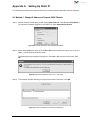
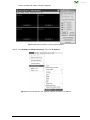
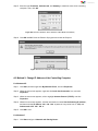
1
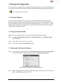
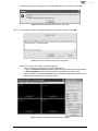
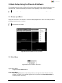
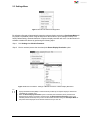
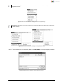
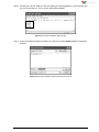
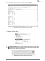
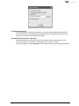
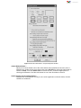
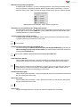
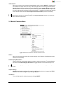
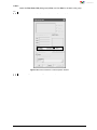
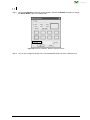
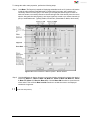
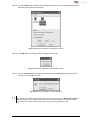
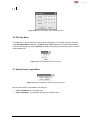
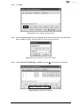
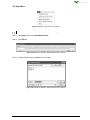
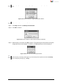
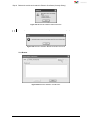
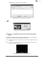
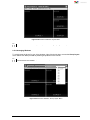
User Manual Sequoia 2H2U One of a kind multiviewing Revision 1.0.0, (May, 2014) User Manual ABOUT THIS MANUAL This manual contains information on how to use Avitech proprietary Phoenix-G (formerly Galaxy) software to configure the Sequoia 2H2U. The following conventions are used to distinguish elements of text throughout the manual. provides additional hints or information that require special attention. identifies warnings which must be strictly followed. Any name of a menu, command, icon or button displayed on the screen is shown in a bold typeset. For example: On the Start menu select Settings. To assist us in making improvements to this user manual, we welcome any comments and constructive criticism. Email us at: [email protected]. WARNING Do not attempt to disassemble the Sequoia 2H2U. Doing so may void the warranty. There are no serviceable parts inside. Please refer all servicing to qualified personnel. TRADEMARKS All brand and product names are trademarks or registered trademarks of their respective companies. COPYRIGHT The information in this manual is subject to change without prior notice. No part of this document may be reproduced or transmitted in any form or by any means, electronic or mechanical for any purpose, without the express written permission of Avitech International Corporation. Avitech International Corporation may have patents, patent applications, trademarks, copyrights or other intellectual property rights covering the subject matter in this document. Except as expressly written by Avitech International Corporation, the furnishing of this document does not provide any license to patents, trademarks, copyrights or other intellectual property of Avitech International Corporation or any of its affiliates. TECHNICAL SUPPORT For any questions regarding the information provided in this guide, call our technical support help line at 425-885-3863, or our toll free help line at 1-877-AVI-TECH, or email us at: [email protected] ii Contents About This Manual .................................................................................................................... ii Technical Support ..................................................................................................................... ii Warranty..................................................................................................................................... v Limitation of Liability ................................................................................................................ v Extended Warranty Options..................................................................................................... v Services and Repairs Outside the Warranty Period .............................................................. v Regulatory Information ............................................................................................................ v Federal Communications Commission (FCC) Statement ..................................................... v European Union CE Marking and Compliance Notices ........................................................ v Australia and New Zealand C-Tick Marking and Compliance Notice .................................. v 1. Phoenix-G Configuration ............................................................................................ 1 1.1 Connection Method ........................................................................................................... 1 1.2 Pinging the Sequoia 2H2U ................................................................................................ 1 1.3 Starting Up the Phoenix-G Software ................................................................................ 1 2. Basic Setup Using the Phoenix-G Software .............................................................. 3 2.1 Group Layout Menu ........................................................................................................... 3 2.2 Select Menu ........................................................................................................................ 3 2.3 Settings Menu .................................................................................................................... 4 2.4 System Parameter Menu ................................................................................................... 8 2.5 Module Parameter Menu ................................................................................................. 12 2.6 GUI View Menu ................................................................................................................. 21 2.7 Special Screen Layout Menu .......................................................................................... 21 2.8 Help Menu ......................................................................................................................... 23 2.9 Quick Keys – Change Window to/from Full Screen Mode; Swap Window Contents 27 2.10 Window Layout ................................................................................................................ 28 2.10.1 Default Window Layouts .................................................................................... 28 2.10.2 Arranging Windows ........................................................................................... 29 2.11 Mouse Right-click Menu.................................................................................................. 30 2.11.1 Resizing Window ................................................................................................ 31 2.11.2 Setting Meter Properties .................................................................................... 33 2.11.3 Setting Label Properties .................................................................................... 33 2.11.4 Setting Border Properties .................................................................................. 34 2.11.5 Setting Alarm ...................................................................................................... 35 2.11.6 Check Signal ....................................................................................................... 36 2.11.7 Auto Remove Black Bar ..................................................................................... 36 2.11.8 Quick Cropping an Image on a Window........................................................... 37 2.11.9 Specifying the Size of a Cropped Image .......................................................... 37 2.11.10 Restore ................................................................................................................ 37 iii 2.11.11 Pan Image ............................................................................................................ 38 2.11.12 Aspect Auto Detect ............................................................................................ 39 2.12 Turning On/Off the Window/Label ................................................................................. 40 2.13 Saving to a Flash File ...................................................................................................... 40 2.14 Saving a Preset ................................................................................................................ 42 2.15 Loading File ...................................................................................................................... 43 2.16 Making Adjustments ........................................................................................................ 44 2.17 Audio Setup ...................................................................................................................... 45 2.18 Control Video Fade .......................................................................................................... 46 Appendix A Setting Up Static IP .................................................................................. 47 A.1 Method 1: Change IP Address of Sequoia 2H2U Chassis ........................................... 47 A.2 Method 2: Change IP Address of the Controlling Computer ...................................... 49 For Windows XP .............................................................................................................. 49 For Windows 7 ................................................................................................................. 49 iv Warranty Regulatory Information Avitech International Corporation (herein after referred to as “Avitech”) warrants to the original purchaser of the products manufactured in its facility (the “Product”), that these products will be free from defects in material and workmanship for a period of 1 year or 15 months from the date of shipment of the Product to the purchaser. There is a 3 month grace period between shipping and installation. Marking labels located on the exterior of the device indicate the regulations that the model complies with. Please check the marking labels on the device and refer to the corresponding statements in this chapter. Some notices apply to specific models only. Federal Communications Commission (FCC) Statement This equipment has been tested and found to comply with the limits for a Class B digital device, pursuant to Part 15 of the FCC Rules. These limits are designed to provide reasonable protection against harmful interference when the equipment is operated in a commercial environment. This equipment generates, uses, and can radiate radio frequency energy and, if not installed and used in accordance with the instruction manual, may cause harmful interference to radio communications. Operation of this equipment in a residential area is likely to cause harmful interference, in which case the user will be required to correct the interference at his own expense. Properly shielded and grounded cables and connectors must be used in order to meet FCC emission limits. Avitech is not responsible for any radio or television interference caused by using other than recommended cables and connectors or by unauthorized changes or modifications to this equipment. Unauthorized changes or modifications could void the user's authority to operate the equipment. Operation is subject to the following two conditions: (1) this device may not cause harmful interference, and (2) this device must accept any interference received, including interference that may cause undesired operation. If the Product proves to be defective during the 1 year warranty period, the purchaser’s exclusive remedy and Avitech’s sole obligation under this warranty is expressly limited, at Avitech’s sole option, to: (a) repairing the defective Product without charge for parts and labor; or (b) providing a replacement in exchange for the defective Product; or (c) if after a reasonable time is unable to correct the defect or provide a replacement Product in good working order, then the purchaser shall be entitled to recover damages subject to the limitation of liability set forth below. Limitation of Liability Avitech’s liability under this warranty shall not exceed the purchase price paid for the defective product. In no event shall Avitech be liable for any incidental, special, or consequential damages, including without limitation, loss of profits for any breach of this warranty. If Avitech replaces the defective Product with a replacement Product as provided under the terms of this Warranty, in no event will the term of the warranty on the replacement Product exceed the number of months remaining on the warranty covering the defective Product. Equipment manufactured by other suppliers and supplied by Avitech carries the respective manufacturer’s warranty. Avitech assumes no warranty responsibility either expressed or implied for equipment manufactured by others and supplied by Avitech. European Union CE Marking and Compliance Notices Statements of Compliance English This product follows the provisions of the European Directive 1999/5/EC. Dansk (Danish) This Warranty is in lieu of all other warranties expressed or implied, including without limitation, any implied warranty of merchantability or fitness for a particular purpose, all of which are expressly disclaimed. Dette produkt er i overensstemmelse med det europæiske direktiv 1999/5/EC. Nederlands (Dutch) Dit product is in navolging van de bepalingen van Europees Directief 1999/5/EC. This Hardware Warranty shall not apply to any defect, failure, or damage: (a) caused by improper use of the Product or inadequate maintenance and care of the Product; (b) resulting from attempts by other than Avitech representatives to install, repair, or service the Product; (c) caused by installation of the Product in a hostile operating environment or connection of the Product to incompatible equipment; or (d) caused by the modification of the Product or integration with other products when the effect of such modification or integration increases the time or difficulties of servicing the Product. Suomi (Finnish) Tämä tuote noudattaa EU-direktiivin 1999/5/EC määräyksiä. Français (French) Ce produit est conforme aux exigences de la Directive Européenne 1999/5/EC. Deutsch (German) Dieses Produkt entspricht den Bestimmungen der Europäischen Richtlinie 1999/5/EC. Any Product which fails under conditions other than those specifically covered by the Hardware Warranty, will be repaired at the price of parts and labor in effect at the time of repair. Such repairs are warranted for a period of 90 days from date of reshipment to customer. Ελληνικά (Greek) To προϊόν αυτό πληροί τις προβλέψεις της Ευρωπαϊκής Οδηγίας 1999/5/EC. Íslenska (Icelandic) Þessi vara stenst reglugerð Evrópska Efnahags Bandalagsins númer 1999/5/EC. Extended Warranty Options Avitech offers OPTIONAL Extended Warranty plans that provide continuous coverage for the Product after the expiration of the Warranty Period. Contact an Avitech sales representative for details on the options that are available for the Avitech equipment. Italiano (Italian) Questo prodotto è conforme alla Direttiva Europea 1999/5/EC. Norsk (Norwegian) Dette produktet er i henhold til bestemmelsene i det europeiske direktivet 1999/5/EC. Services and Repairs Outside the Warranty Period Avitech makes its best offer to repair a product that is outside the warranty period, provided the product has not reached its end of life (EOL). The minimum charge for such repair excluding shipping and handling is $200 (US dollars). Português (Portuguese) Este produto cumpre com as normas da Diretiva Européia 1999/5/EC. Español (Spanish) Este producto cumple con las normas del Directivo Europeo 1999/5/EC. AVITECH INTERNATIONAL CORPORATION ● 15377 NE 90th Street Redmond, WA 98052 USA ● TOLL FREE 1 877 AVITECH ● PHONE 1 425 885 3863 ● FAX 1 425 885 4726 ● [email protected] ● http://avitechvideo.com Svenska (Swedish) Denna produkt har tillverkats i enlighet med EG-direktiv 1999/5/EC. Australia and New Zealand C-Tick Marking and Compliance Notice Statement of Compliance This product complies with Australia and New Zealand's standards for radio interference. v 1. Phoenix-G Configuration The Avitech Phoenix-G program (formerly Galaxy) requires no installation. Just copy the system files to your computer’s hard drive. This chapter introduces Phoenix-G software for setting up Sequoia 2H2U. Make sure the Sequoia 2H2U is powered on and connected properly to your computer through Ethernet before launching the Phoenix-G software. 1.1 Connection Method Connect your Sequoia 2H2U to the controlling computer through an Ethernet (IP address) cable. Before connecting the computer to the Sequoia 2H2U, the computer with DHCP LAN connection will need to be changed to static IP, similar range as the Sequoia 2H2U (e.g., ”210.100.100.151” – factorydefault setting). Or, change the IP address of the Sequoia 2H2U to a similar range as the controlling computer. See Appendix A for details. 1.2 Pinging the Sequoia 2H2U Make sure you can ping the chassis at “210.100.100.151” (factory-default IP address). Step 1. Click StartAll ProgramsAccessoriesCommand Prompt. The Command Prompt screen will appear. Step 2. Type “ping 210.100.100.151” and press Enter. Step 3. Type “exit” to exit the Command Prompt screen. 1.3 Starting Up the Phoenix-G Software Step 1. Run the Phoenix-G software by double-clicking Phoenix-G.exe. Under IP select User Define if you know the IP address assigned to the Sequoia or select Automatically Search. Figure 1-1 Phoenix-G Software: Set Communication Mode Step 2. Before clicking OK (next step), press the Ctrl + Esc keys to make sure that you are not in host (MKC – mouse keyboard controller) mode. 1 The following message may appear in case Ctrl + Esc keys was not pressed. Click OK. Figure 1-2 Phoenix-G Software: Press “Ctrl” + “Esc” Keys Step 3. The computer will start searching for Sequoia and confirm connection. Click OK. Figure 1-3 Phoenix-G Software: Connection Configuration Phoenix-G “Control” and “Option” window will appear. “Control” window is for creating and configuring the layout. Logo icon Avitech Phoenix-G (Galaxy): proprietary logo and the name of the software. 1920×1200 (60Hz): shows the output resolution and frequency of the monitor. “Option” window is for video window/label setup; save/load file; adjust image; window size/ position setting, monitor audio, and fader control. Figure 1-4 Phoenix-G Software: Control and Option Window 2 2. Basic Setup Using the Phoenix-G Software This chapter introduces you to the Phoenix-G (formerly Galaxy) software for setting the features of your Sequoia 2H2U; as well as familiarizes you with the menus appearing on the Phoenix-G software. Some items appearing on the menus of the Phoenix-G software may not be available (grayed-out). 2.1 Group Layout Menu Right-click the mouse on the title bar to access the Group Layout menu. Select from 2×2 up to 8×8 as possible grid positions on the monitor. The layout size available for your particular model will depend on the monitor’s resolution as well as the smallest window size limitation. Figure 2-1 Phoenix-G Software: Group Layout Menu 2.2 Select Menu Figure 2-2 Phoenix-G Software: Select Menu Open Option Menu Toggle on/off the Option window. Dock Option Menu Return the Option window to its default position on the right side of the Phoenix-G control window. This option is not available (grayed-out) if the previous item Open Option Menu is disabled (without checkmark). 3 2.3 Settings Menu Figure 2-3 Phoenix-G Software: Settings Menu By default the Sequoia will automatically detect the optimum display resolution so Set Output Mode will be grayed-out (disabled). When using the Sequoia for the first time or upon setting the device to its factory-default setting, automatic detection of optimum display resolution will occur. Use the Phoenix-G software to disable this feature by performing the following steps: Step 1. Click Settings then Module Parameter. Step 2. Click to unselect (remove the checkmark) the Detect Display Resolution option. Figure 2-4 Phoenix-G Software: “Settings””Module Parameter””Detect Display Resolution” 1. 2. When the monitor is unable to provide the EDID signal it will display at 1024×768 / 60Hz. The extended display identification data (EDID) is a data structure provided by a computer display to describe its capabilities to a graphics card. When the Detect Display Resolution option is selected (with checkmark) all the presets will be displayed in the optimum resolution. Likewise, when the Detect Display Resolution option is not selected (without checkmark) and you have set the desired resolution using the Set Output Mode all the presets will be displayed in the desired resolution that you have set. 4 Step 3. Click Settings and then click Set Output Mode. Figure 2-5 Phoenix-G Software: “Settings””Set Output Mode” When the Detect Display Resolution option is “on” the Set Output Mode function is not available (grayed-out). Step 4. Set the output resolution to match the monitor’s resolution. Select the Refresh Frequency, select the Mode and then click OK. You will notice that the selected resolution is displayed on the title bar of Phoenix-G software. Figure 2-6 Phoenix-G Software: Select ”Refresh Frequency” and “Mode” Upon changing the output resolution the output windows appearing on the monitor may overlay or in the case of fixed window layout (e.g., 2×2, 3×3, 4×4, etc.) misalignment may occur. Choose a new window layout to fix this. When the Flashing Window Border option is enabled (with checkmark) the border of the window where the mouse cursor just resided will blink twice to notify you of its location. Figure 2-7 Phoenix-G Software: “Settings””Flashing Window Border” 5 When you have unplugged the IP cable and re-connected it, click Reconnect (Network) to continue the configuration process. Figure 2-8 Phoenix-G Software: “Settings””Reconnect (Network)” ® Import/Export (.txt) allows you to import a label from / export label to Microsoft Office Word or Notepad to be edited externally. Figure 2-9 Phoenix-G Software: “Settings””Import/Export (.txt)” Step 1. The convenient way is to export file (label) as a Label (ANSI) “txt” file by assigning a filename. Figure 2-10 Phoenix-G Software: Export Label as Text File 6 Step 2. Edit the text in the file. When you are done editing the label (highlighted as shown below) save the “txt” file and import it. The on screen labels will be updated. Figure 2-11 Phoenix-G Software: Edit the Label Step 3. Export all firmware/hardware information to a text file by clicking Export (.txt) and assigning a filename. Figure 2-12 Phoenix-G Software: Export Information as Text File 7 Step 4. Click Save. The next screen shows the text file opened using Notepad. Figure 2-13 Sample Firmware/Hardware Information Text File 2.4 System Parameter Menu Figure 2-14 Phoenix-G Software: “System Parameter” Menu Save System Files to Flash allows you to save all configuration settings to flash memory. If the system configuration has been changed, save the changes first before continuing the other configuration settings. The progress of saving to flash memory will be displayed. Figure 2-15 Phoenix-G Software: Save System Files to Flash 8 Figure 2-16 Phoenix-G Software: “Advanced” Use Broadcast Load File – is for loading presets / switching resolution / group reset. When enabled (with checkmark), Phoenix-G software will broadcast the command allowing for simultaneous execution of the command. This feature should always be enabled. Automatically Backup Files to Hard Drive – When enabled (with checkmark) the Phoenix-G software will save all backup files to the computer hard drive’s “c:\Avitech_VCC\Backup\IP210.100.100.151” folder. You may change this by clicking Browse to select different location to save backup information. 9 Figure 2-17 Phoenix-G Software: “Sequoia Properties” Window Active Window Border – Allows you to set the border color of the active window. Each pixel/line can be set to have a different color; all lines can be set to be the same color (All lines) by clicking the radio button to select the Line #. Then click Select color to choose the color. There are eight options for choosing the 3D border. Click the radio button for one of the 3D borders to select it. Switch primary and secondary buttons – Swap the two mouse buttons so that you can use the right button as the left button, click the checkbox to enable this. 10 Window priority (manual designate) – If enabled (with checkmark) – in case of overlaying windows, upon clicking a window will not cause the window to become the topmost window. Disable (without checkmark) or click the particular button on the “Option” window to change window priority (become topmost window). Figure 2-18 Phoenix-G Software: “Option” Window Priority Button Hide Enter icon and disable mouse double-click function – If enabled (with checkmark) – the “enter icon” will not appear upon moving the Host cursor to the top right corner of a particular window nor will double-clicking the left mouse button allow switching operation to a remote computer. Transfer control to this remote computer – If enabled (with checkmark) – keyboard/ mouse control will transfer to the particular window (computer) that has just entered full screen mode. Default setting is disabled (keyboard/mouse control does not transfer to a particular computer that enters full screen mode). Remain full screen upon pressing Pause/Break key – Click the radio button for Remain full screen upon pressing Pause/Break key under the item When returning from full screen to host mode if you wish to remain in full screen mode upon pressing the Pause/Break key. Default setting is Return to previous layout upon pressing Pause/Break key. Swap with active window – When enabled (with checkmark) – the action of entering a computer window (other than the current active window) will cause both active and newly entered windows to swap position. 1. Default setting is enabled for this item. 2. When this item is disabled, pressing the F# hotkey (or double-click) will not cause both active and newly entered windows to swap position. Likewise, pressing Shift + F# hotkey (or Shift + double-click) will cause both active and newly entered windows to swap position. Disable label/tally display – When enabled (with checkmark) – label and tally will be turned off to the particular window that has just entered full screen mode. With audio output – When enabled (with checkmark) – audio output will be turned on in the particular window that has just entered full screen mode. Default setting is disabled for these items. Select color – Change the background color of the pop-up selections (default color is dark blue). 11 Audio Status – Allows you to set the color indicator showing whether audio is turned On/Off for a window (only one window can output audio at a time). There are eight colors for choosing the audio status. Click the On radio button, and then click one of the color boxes to select. Do the same for the Off radio button. You can also turn on (with checkmark) / off the Audio indicators. By default the audio output would correspond to the active window. To enable audio output other than the active window disable the item Audio output from active window (remove checkmark). Click OK when finished and exit the Sequoia Properties window. The Phoenix-G software still retains the settings until the next time you change the settings in the Sequoia Properties window or you return the system to the factory-default state. 2.5 Module Parameter Menu Figure 2-19 Phoenix-G Software: “Module Parameter” Menu Reset – Allows you to refresh the module (the current settings on the Phoenix-G software will be the same as for the module). Detect Display Resolution – Sequoia 2H2U can automatically detect the display’s optimum resolution. To enable/disable this feature click Detect Display Resolution to toggle between on (with checkmark) or off. When the Detect Display Resolution option is set to On all the presets will be displayed in the optimum resolution. Output Timing – Normal output timing is designed for some brands of monitor that do not support the VESA standard. The default setting for output timing is Normal. All Labels – Turn on/off all labels for all the windows by clicking ON/OFF. 12 Label – Adjust the Font Color, B-G (background) Color, and font Size for all labels in the group. Make sure to turn on all labels (see previous item) before setting the label properties. Figure 2-20 Phoenix-G Software: “Label Properties” Window Each window supports one line of text (up to 31 characters). 13 Borders are turned on by default. Step 1. Upon clicking Border the following screen appears. Remove the Enable checkmark or change the Border Width to 0 to turn off the border. Figure 2-21 Phoenix-G Software: “Border Properties” Window Step 2. You can also change the border color. Each pixel/line/3D border can have a different color. 14 To change the audio meter properties, perform the following steps: Step 1. Click Meter. The Sequoia is capable of displaying embedded audio as VU (volume unit) meters inside the video window. Embedded audio is divided into four groups, with a master and secondary channel for each group. This allows you to display the left and right VU meter of either the master or secondary channel on the left and right side of the window just as the menu depicts. Along with the video signal(s), each input signal may contain up to sixteen channels (8 pairs) of embedded audio. Typically, 48kHz, 20-bit audio; (extendable to 48kHz, 24-bit audio). Figure 2-22 Phoenix-G Software: “Meter Properties – Module” Window Step 2. Click the All button to display all meters or click the checkbox individually to display the desired meter only (Meter 1 L, Phase 1, Meter 1 R, Meter 2 L, Phase 2, Meter 2 R, Meter 3 L, Phase 3, Meter 3 R, Meter 4 L, Phase 4, Meter 4 R). Click the Meter SW checkbox to open/close the meter switch. Then click the Meter outside checkbox to enable the meter to be displayed outside the image area. “Meter outside” is not allowed if the image area is less than 140×64 pixels (does not include the window border and label portions). 15 Step 3. Use the slider to adjust the Phase (one slider) – 128 (default); When monitoring a stereo signal, the coherence between the 2 channels (i.e., how similar they are) greatly affects its mono compatibility. The phase meter indicate the relative phase of the 2 channels and thereby provide some measure of mono compatibility. Phase meter reading in the upper half of the scale indicate acceptable mono compatibility, whereas lower half readings warn of a potential compatibility problem. Use the slider to adjust the VU (volume unit – one slider) – refer to the above figure Alignment: –27.9 dBFS (decibels relative to full scale; default); user adjustable; also known as safe range. Alarm: 0 to –13.95 dBFS (default); 0 to –20 dBFS depending on “alignment” setting; the “alarm” range is equivalent to the upper half of 0 dBFS minus previous item “alignment” setting. Headroom: –14 to –27.9 dBFS (default); –20.7 to –41.58 dBFS depending on “alignment” setting the “headroom” range is equivalent to the lower half of 0 dBFS minus “alignment” setting; also known as the headroom before alarm range is reached. Use the slider to adjust the Sound (High/Low sliders). For 3G / HD-SDI signal – selecting the primary channel without embedded audio will cause the secondary channel to lose its audio output. Step 5. Use the slider to adjust the Width and the Transparency of the meter appearing on screen. Step 6. Select the meter’s Ballistics (absolute movement of the meter's pointer). Meters which monitor audio levels are typically one of two varieties: VU (Volume Unit) or PPM (Peak Program Meters). Though both perform the same function, they accomplish the function in very different manners. A VU meter displays the average volume level of an audio signal (relatively slower response and is driven from a full-wave averaging circuit). A PPM displays the peak volume level of an audio signal (shorter integration time so that only peaks wide enough to be audible are displayed). For a steady state sine wave tone, the difference between the average level (VU) and the peak level (PPM) is about 3 dB. But for a complex audio signal (speech or music), the difference between the average level (VU) and the peak level (PPM) can be 10 to 12 dB. This difference between the reading of a VU meter and a PPM is known as the crest factor. Whereas the VU meter has fairly equal attack and release times, the PPM is characterized by having a very slow fall-back time, taking over 1.5 seconds to fall back 20dB. The reasoning for the slow fall-back was to reduce eye-fatigue and make the peak indication easier to assimilate. 16 Setting Alarm Properties allows you to setup the notification when a signal is missing. To set the alarm properties, click Alarm. By clicking Module Alarm Switch you will set the Process/Video Alarm Switch and adjust the No Video’s Response Time. By clicking Audio Alarm Switch you will set the No Audio Alarm for Single Meter and adjust the Signal In/Out’s Response Time Figure 2-23 Phoenix-G Software: “Alarm Properties – Module” Window OSD allows you to turn on (with checkmark) or off your Sequoia’s OSD (on screen display) feature. Click the item to toggle between on/off. There are three Window Sizes that can be selected to display the windows in a group: 4:3, 16:9, or Lock Aspect Ratio. When changing the width of the window the height will automatically adjust to match the aspect ratio. When Lock Aspect Ratio is set On the aspect ratio of the video display will be maintained, even if the window is stretched. If the image is 4:3 and it is stretched to 16:9 the results are two vertical black bars appearing on either side of the display. If the image is 16:9 and it is scaled down to 4:3 then it will have a letterbox effect. Figure 2-24 Phoenix-G Software: “Window Size””Lock Aspect Ratio” 17 Background Picture allows you to select a BMP picture file to fill up the entire monitor screen in order to prevent the display of dark (empty) patches (e.g., spaces between windows). You can turn on (with checkmark on Enable) or off the display of background picture. Figure 2-25 Phoenix-G Software: “Background Picture” Window Step 1. Click the Enable checkbox to toggle between on/off. Step 2. When only one or no BMP picture file has been saved to your module’s flash memory, click the Save button. Figure 2-26 Phoenix-G Software: “Select File to Save to Module” Window Step 3. Select the desired background picture file. Then click Save. 18 To fill the entire screen of monitor, the size (pixel) of the background picture must be the same as the monitor resolution. In case the size of the file is larger than the Sequoia’s output resolution (see Settings Set Output Mode) the system will automatically detect and prevent it from displaying as your background picture (WARNING message will appear). Figure 2-27 Phoenix-G Software: “Size of Picture is Greater Than Output Resolution” Warning The background picture file must conform to the following conditions– 1. BMP file format 2. 24-bit color 3. Size up to 1920×1200 pixels only 4. Up to two background picture files can be stored to flash memory only Progress of updating the background picture to flash memory would be shown. Figure 2-28 Phoenix-G Software: Progress of Updating Background Picture to Flash Memory Step 4. Click OK. Figure 2-29 Phoenix-G Software: File Successfully Saved In case the updating process is prematurely terminated, no background picture will appear on screen (dark background). Perform the above steps again to correct this. 19 Step 5. Click the Load button to select another background picture file (in case two background picture files have been saved to flash memory). Figure 2-30 Phoenix-G Software: Load Background Picture Step 6. Click OK upon successfully loading a background picture file. Figure 2-31 Phoenix-G Software: File Loaded Successfully Step 7. Or, click the Delete button to remove a previously saved background picture file from flash memory. Then click OK to confirm. Figure 2-32 Phoenix-G Software: Confirm File Deletion For all types of NTSC programming, captions are "encoded" into line 21 of the vertical blanking interval – a part of the TV picture that sits just above the visible portion and is usually unseen. Display Closed Caption (line 21) allows you to turn on (with checkmark) or off your Sequoia’s display of the “encoded” caption appearing on your monitor screen’s topmost line. Click the item to toggle between on/off. 20 IP Address allows you to change to an IP address different from the default one. Figure 2-33 Phoenix-G Software: “Set IP Address” Window 2.6 GUI View Menu This allows you to set the Phoenix-G control window’s display size. For example, when the resolution under Set Output Mode is 800×600, the GUI View set at 50 % would give you a 400×300 Phoenix-G control window display size; while a GUI View set at 25 % would give you a 200×150 Phoenix-G control window display size. Figure 2-34 Phoenix-G Software: “GUI View” Menu 2.7 Special Screen Layout Menu Figure 2-35 Phoenix-G Software: “Special Screen Layout” Menu Special screen layouts are available for the Sequoia: Layout 1 (Default 2×2) – quad split mode Layout 2 (Briefing) – cycle between presets for a slideshow effect 21 Step 1. Click Add. Figure 2-36 Phoenix-G Software: “Briefing” Window Step 2. Enter the Process name, specify the Time (H : M : S), then select the previously saved preset File. Click OK to continue. Continue adding new processes as necessary. Figure 2-37 Phoenix-G Software: “Add Process” Window Step 3. Select Auto Play, Play Manually, or Repeat. Click play to start viewing the slideshow. Figure 2-38 Briefing: Select Type of Playback 22 2.8 Help Menu Figure 2-39 Phoenix-G Software: “Help” Menu To Read the Avitech Sequoia’s BIOS Version, perform the following steps: Step 1. Click Help and then click Read BIOS Version. Step 2. Click Export. Figure 2-40 Phoenix-G Software: “Display BIOS Version” Window Step 3. Assign a filename and click Save to save the data. Figure 2-41 Phoenix-G Software: “Export All Information” Window 23 To update signal type/format, click Update Signal Type/Format and the image’s signal type/format will be shown. Figure 2-42 Phoenix-G Software: “Signal Type/Format” Window To backup a preset, perform the following steps: Step 1. Click Help and then click Backup All Information. Step 2. Click OK to continue. Figure 2-43 Phoenix-G Software: Old Information Deletion Confirmation Step 3. When backup is successful, click OK to continue. This will backup all saved presets and system configuration files to the computer’s “c:\Avitech_VCC\Backup\IPxxx.xxx.xxx.xxx\xxxx#_#”. Figure 2-44 Phoenix-G Software: Backup Successful Everything in the Backup folder will be erased. If you have previously backed up presets, they will all be written over when you backup presets again. If you want to keep the old presets move the entire Backup folder to a temporary directory (e.g., c:\temp). 24 To manually restore a preset perform the following steps: Step 1. Set the Sequoia to the factory-default value. Step 2. If the backup content is somewhere else other than at the “c:\Avitech_VCC\Backup\IPxxx.xxx.xxx.xxx\xxxx#_#”, copy the backup data “xxxx#_#” into the “c:\Avitech_VCC\Backup\IPxxx.xxx.xxx.xxx\” location. Step 3. Run the Phoenix-G software and select Yes when prompted whether to restore the Sequoia using the backup data. Step 4. Click Help and then click Restore Module Information. Step 5. If the checking result confirms that everything is normal (All Normal !!), click Cancel to exit the restoring of preset(s). If the checking result shows an Abnormal report, continue on. Figure 2-45 Phoenix-G Software: ”Check Module Information” Window Step 6. Confirm if the backup Path is correct. If backup Path is incorrect, click Browse to select correct location. Step 7. Click to enable the Forces checkbox (located on the upper right corner) that allows the backup information to be written to all the module(s) flash memory. Then click Restore. Figure 2-46 Phoenix-G Software: Progress of Restore Process 25 Step 8. Reboot the module and restart the Phoenix-G software (formerly Galaxy). Figure 2-47 Phoenix-G Software: Restart Phoenix-G If upon clicking Restore Module Information on the Help menu and the error message appears click OK. Figure 2-48 Phoenix-G Software: Module Information Not Found Click Browse. Figure 2-49 Phoenix-G Software: Click “Browse” 26 Click Browse again to specify the correct backup Path. Figure 2-50 Phoenix-G Software: Specify Correct Backup Path To find out the Phoenix-G software version, click Help and then click About. Figure 2-51 Phoenix-G Software: Version Information 2.9 Quick Keys – Change Window to/from Full Screen Mode; Swap Window Contents Two quick keys are available to quickly bring a window to/from full screen mode as well as swap the contents from one window to another by performing the following steps: Step 1. To change to full screen mode, double-click the window. Double-click again to return from full screen mode. Step 2. To access the swap window quick key move your cursor to the bottom left hand corner of a window until a capital letter S appears. Figure 2-52 Phoenix-G Software: Swap Window Quick Key 27 Step 3. Click the capital letter S to select the source window and then click again at a destination window where you want to swap the contents from the source. This will swap all the contents and properties of the source window to the destination window. 2.10 Window Layout 2.10.1 Default Window Layouts Three default window layouts are available: Figure 2-53 Phoenix-G Software: “layout1.GP1” Figure 2-54 Phoenix-G Software: “layout2.GP1” 28 Figure 2-55 Phoenix-G Software: “layout3.GP1” To switch between the three factory-default presets use the Page Up/Page Down keys. 2.10.2 Arranging Windows To quickly setup the layout for your video windows, right-click the title bar to access the Group Layout menu. Select from 2×2 up to 8×8 as possible grid positions on the monitor. The layout size available for your particular model will depend on the monitor’s resolution as well as the smallest window size limitation. Figure 2-56 Phoenix-G Software: “Group Layout” Menu 29 To reposition a window, drag the center of a window and drop to a new position and it will update on the monitor. Or, use the Position Fine Adjustment menu to adjust the position of any window on a pixel by pixel basis. Keep in mind that width increases in 16 pixel increments and height in 1 pixel increments. Figure 2-57 Phoenix-G Software: “Position Fine Adjustment” Window 2.11 Mouse Right-click Menu To change the properties of an individual window, right-click the particular window to access the window’s menu. Figure 2-58 Phoenix-G Software: Window Right-click Menu 30 2.11.1 Resizing Window To resize a single window to one of the preset sizes perform the following steps: Step 1. Right-click a particular window and select Size followed by the desired preset size selection. Figure 2-59 Phoenix-G Software: “Size” Menu Step 2. Alternatively, resize a window by dragging the border of a window to the desired size. Step 3. Another option is to use Size Fine Adjustment menu to adjust each window on a pixel by pixel basis. Keep in mind that width increases in 2 pixel increments and height in 1 pixel increments. Figure 2-60 Phoenix-G Software: “Size Fine Adjustment” Window 31 Full Screen – On a particular window select this to maximize the image and fill up the whole screen. You can click the desired window button to switch windows in full screen mode. Figure 2-61 Phoenix-G Software: “Full Screen Mode” Window Full screen in background – If so desired, select this (with checkmark) to allow the window (image) in full screen mode to appear in the background. Select Full screen in background (without checkmark) to allow the window (image) in full screen mode to reappear in the foreground (fill up the whole screen). 32 2.11.2 Setting Meter Properties Upon right-clicking a particular window, select Meter to change the audio meter properties. Refer to a previous section for details on setting the Meter Properties. Figure 2-62 Phoenix-G Software: “Meter Properties – Process” Window 2.11.3 Setting Label Properties Step 1. Right-click a window and select Label to enter text. Figure 2-63 Phoenix-G Software: Right-click Window and Click “Label” 33 Step 2. Each window supports one line of text (up to 31 characters). Figure 2-64 Phoenix-G Software: “Label Properties” Window 2.11.4 Setting Border Properties Borders are turned on by default. To turn off the border perform the following steps: Step 1. Click Border. Figure 2-65 Phoenix-G Software: Set Border Width Step 2. Change the Border Width to 0. 34 Step 3. You can also change the border color. Each pixel/line can have a different color 3D border 2.11.5 Setting Alarm Upon right-clicking a particular window, select Set Alarm. Figure 2-66 Phoenix-G Software: “Alarm Properties – Module” Window Module/Process Alarm Switch: to turn on the alarm setting make sure that both options are enabled (with checkmark) Video Alarm Switch: to turn on/off the “no video” signal Response Time (Second): to set the “no video” alarm response time from 0 to 23 seconds Audio Alarm Switch: to turn on the alarm setting, make sure this is enabled (with checkmark) Response Time (Second): to set the “signal in/out” alarm response time from 0 to 23 seconds 35 2.11.6 Check Signal To determine if the video signal is being fed into the selected window, right-click a particular window and click Check Signal. One of the following screens may appear: Figure 2-67 Phoenix-G Software: “Signal Type” Window 2.11.7 Auto Remove Black Bar Ever notice those annoying black bars on the sides or along the top and bottom of a video? Oftentimes, the culprit is an incorrectly set aspect ratio. The black bars serve to fill in the empty space that is left behind when the video does not fill up the entire frame. Usually, the video will be blown up to fit the frame, but in order to avoid distorting the picture or cutting off part of the video, the item you are placing inside the frame will maintain its aspect ratio (this is a good thing). When you notice black bars, right-click the particular window and select Auto Remove Black Bar (with checkmark) to try to fix this problem. 1. 2. This function is applicable for HDMI and DVI input signal only. When enabling this function, make sure the image does not have a black or dark grey background to avoid cropping off part of the image. Figure 2-68 Phoenix-G Software: Auto Remove Black Bar 36 2.11.8 Quick Cropping an Image on a Window This allows you to crop (cut-out) an image on a particular window. Click Quick Crop Image Box Size to create a starting point and then drag to the desired location. Release the mouse to set the end point. A cropped out image of the former window will be created. The smallest allowed size of crop area is 96×80 pixels based on the Sequoia’s output resolution (not based on the “source” resolution). 2.11.9 Specifying the Size of a Cropped Image This allows you to set the specific size of the crop (cut-out) image on a particular window. Freely adjust the horizontal (Left and Right) and vertical (Top and Bottom) markers, or enter the numerical value to set the size of the cropped image. You can also click the buttons to make smaller adjustments to the markers. Example 1: if the Sequoia’s output resolution is set at 1920×1200 but the input source resolution is 1920×1080, then pressing any of the four buttons on a 25 % magnification would effect a proportionally four pixel horizontal adjustment, while a 50 % or 100 % magnification would effect a proportionally two pixel horizontal adjustment. Example 2: if the Sequoia’s output resolution is set at 1024×768 but the input source resolution is 1920×1080, then pressing any of the four buttons on a 25 % magnification would effect a proportionally six pixel horizontal adjustment, while a 50 % or 100 % magnification would effect a proportionally two pixel horizontal adjustment. Then click Update. A cropped-out image of the former window will be created. Figure 2-69 Phoenix-G Software: “Setting Crop Size” Window 2.11.10 Restore This allows you to undo the previous cropping action and restore the image prior to cropping (1:1). Then adjust (enlarge) the window size manually by dragging on the sides/corners. 37 2.11.11 Pan Image Click Pan Image. This allows you to use the mouse (drag using the symbol) to pan (see the NOTE below for description of pan) the cropped image window (zoom in area). You can also click the X– / X+ / Y– / Y+ (x / y-axis coordinates, plus or minus) or H– / H+ / W– / W+ (height/width, plus or minus) buttons to make smaller adjustments. Figure 2-70 Phoenix-G Software: “Pan Region-of-Interest” Window To pan is to move the image around in the image window, usually when the image is larger than its window. Panning changes the image view in the same way that scrolling moves the image up, down, to the left, or to the right in the image window. When the entire image is not displayed you can quickly pan to see parts of the image that were previously hidden. 38 2.11.12 Aspect Auto Detect By default, the image appearing inside a window will be shown in its native aspect ratio. This means that upon dragging the border to enlarge or shrink a window, the aspect ratio will still be maintained. By default, the image is also made to “Fit window size.” This means that the window’s size will conform to the aspect ratio of the image. If this item is disabled, black bars will be shown on areas that are not covered by the image upon dragging the window border. Select “Custom default” instead of “Auto detect” under “Sync Type” to set the input signal’s aspect ratio for a particular window. If the input signal is a different aspect ratio than the monitor in which it is displayed, you may change the monitor’s aspect ratio to display the signal without deformation. Figure 2-71 Phoenix-G Software: “Aspect Auto Detect” Window For example: 1366×768 or 1360×768 (Wide eXtended Graphics Array – Wide XGA or WXGA) are both considered as none standard display resolution. A 16:9 (approximate) aspect ratio will be applied. This means that when displaying at 16:9, it will be readjusted to 1360×765 display resolution. 39 2.12 Turning On/Off the Window/Label Step 1. The Option window has two checkboxes that can be used to close an image window (W) or turn off the label (L) for each window. Figure 2-72 Phoenix-G Software: “Option” Window (W and L) Step 2. To turn off a window or label find the checkbox that represents the selected window and check to enable or un-check to disable the Window or Label. 2.13 Saving to a Flash File There are 2 instances for which you will need to use the save to flash feature: After creating the master layout and you want the Sequoia to load it again when the unit is power cycled (shutdown and restart). After you are done saving presets and you want to save all the presets that were created (up to 23) into the internal flash memory of the Sequoia. If this action is skipped the Sequoia will lose all the presets that were created. 40 To save to flash perform the following steps: Step 1. Click Save File in the Option window. Figure 2-73 Phoenix-G Software: Click “Save File” in “Option” Window Step 2. Click Update to Module Flash and then click OK. Figure 2-74 Phoenix-G Software: “Save File” Window 41 Alternatively, close the Phoenix-G software and select Yes when prompted to save. 2.14 Saving a Preset All the presets you create (up to 23) are stored in the Sequoia, not in the computer that is running the Phoenix-G software. In order to write all the presets into the internal flash memory of the Sequoia after creating it you will need to save to flash. To save a preset, perform the following steps: Step 1. Configure the layout you want the Sequoia to display. Step 2. Click Save File in the Option window. Step 3. Enter a unique filename for the preset and select OK to save. The file extension “GP#” will be automatically added to the file name. Figure 2-75 Phoenix-G Software: “Save File” Window Enter Unique Filename Step 4. Repeat the above steps for each additional preset. Step 5. After you are done creating presets load the file that you want to be the master layout which gets loaded when the module is powered on. Step 6. Close the Phoenix-G software and select Yes when prompted to save to flash. 42 2.15 Loading File Step 1. In the Option window click Load File. Step 2. Select a saved file and then click OK to load the preset. 1. 2. 3. When saving your preset do not use the same filename as the system’s default preset filename (layout1.GP1 / layout2.GP1 / layout3.GP1). The sequence for loading the preset file when using the hotkeys ( / arrow keys) is based on the time when the preset file was first created and saved. Subsequent modification and saves will not affect this sequence (order). The hotkey Ctrl + S can save the latest preset to flash memory so that on the next boot-up the preset will be loaded. 43 2.16 Making Adjustments Step 1. In the Option window click Adjustment. Step 2. Select the Image Window then adjust the input signal such as, Brightness (–128 – 127), Saturation (0 – 2047), Contrast (0 – 1023), and Hue (–1024 – 1023) parameters directly by using the sliders or clicking the radio button. Click the Default button on the lower right portion of the screen to reset the values to the factory-default. Figure 2-76 Phoenix-G Software: “Image Adjustment” Window Saturation and Hue is not available for HDMI/DVI signal input. 44 2.17 Audio Setup Step 1. In the Option window click Check Audio. Step 2. Click the audio Check option. Figure 2-77 Phoenix-G Software: “Check Audio Source” Window Step 3. Select the Process window on the drop-down menu. Step 4. Select the correct Input Source (Analog/Digital (HDMI)). Step 5. Select the desired input Channel (Channel 1 to 4). Step 6. Select the type of output Sound (Stereo / Mono Left / Mono Right). Step 7. Select the desired Output channel (Speaker / HDMI OUT). Step 8. Use the slider to set the Audio Delay time (Millisecond). Step 9. Use the slider to select the desired Volume level (0 to 9). Click the Mute checkbox to quickly turn off the volume. Step 10. Use the slider to set the Audio Fade-in time (Second). Step 11. Click the Update button and click OK to exit. 45 2.18 Control Video Fade This allows you to set the speed that an overlaying window will fade into the background when another window becomes the active window. Step 1. In the Option window click Fader Control. Step 2. Adjust Fading Speed directly by using the slider to select Slow (1) – Fast (10). Then click OK. Figure 2-78 Phoenix-G Software: “Fader Control” Window 46 Appendix A Setting Up Static IP The following two methods allow Sequoia 2H2U to be in same network mask with connected computer. A.1 Method 1: Change IP Address of Sequoia 2H2U Chassis Step 1. Run the Phoenix-G software by double-clicking Phoenix-G.exe. Under IP select User Define if you know the IP address assigned to the Sequoia or select Automatically Search. Figure A-1 Phoenix-G Software: Set Communication Mode Step 2. Before clicking OK (next step), press the Ctrl + Esc keys to make sure that you are not in host (MKC – mouse keyboard controller) mode. The following warning message may appear in case Ctrl + Esc keys was not pressed. Click OK. Figure A-2 Phoenix-G Software: Press “Ctrl” + “Esc” Keys Step 3. The computer will start searching for Sequoia and confirm connection. Click OK. Figure A-3 Phoenix-G Software: Connection Configuration 47 “Control” window and “Option” window will appear. Figure A-4 Phoenix-G Software: Control and Option Window Step 4. Click Settings then Module Parameter. Then click IP Address. Figure A-5 Phoenix-G Software: Click “Settings””Module Parameter””IP Address” 48 Step 5. Enter the new IP address, Subnet mask, and Gateway to match the value of the controlling computer. Then, click OK. Figure A-6 Phoenix-G Software: Set IP Address, Subnet Mask and Gateway Step 6. Click OK and OK. Close the Phoenix-G program and restart the Sequoia. Figure A-7 Phoenix-G Software: Close and Restart Sequoia A.2 Method 2: Change IP Address of the Controlling Computer For Windows XP Step 1. Click Start, and then right-click My Network Places, and click Properties. Step 2. When the next screen appears, right-click the Local Area Connection icon, and click Properties. Step 3. When the next screen appears, click to highlight Internet Protocol (TCP/IP), and click Properties. Step 4. When the next screen appears, click the radio button to select Use the following IP address:, and then enter the IP address: 210 . 100 . 100 . x (where x is any value from 1 – 253) and Subnet mask: 255 . 255 . 255 . 0. Step 5. Click OK to exit. For Windows 7 Step 1. Click Start and type in Network and Sharing Center. 49 Step 2. Click Change Adapter Settings on the left. Step 3. Right-click the Local Area Connection the Sequoia is connected to and select Properties. Step 4. When the next screen appears, click to highlight Internet Protocol Version 4 (TCP/IPv4), and click Properties. Step 5. When the next screen appears, click the radio button to select Use the following IP address:, and then enter the IP address: 210 . 100 . 100 . x (where x is any value from 1 – 253), and Subnet mask: 255 . 255 . 255 . 0. Step 6. Click OK to exit. 50