1
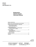
Automatic Screw Feeder 自動ネジ供給機 Automatic Screw Feeder QUICHER Series NSBI² NSRI Type Operation Manual (Maintenance) Operation Manual Read these instructions for the proper use of this machine. Read these instructions for the proper use of this machine. After having these instructions, After having readread these instructions, keep them in a convenient place so you or the operator can to them whenever keep them in arefer convenient placenecessary. so you or the operator can refer to them whenever necessary. ATTENTION : www.ohtake-root.co.jp is the only web site associated with our company. We do not have any branches in China. ྛ栦ᐈ実ὀព㸸ࠕwww.ohtake-root.co.jp ᩎྖ၏୍ⓗᐁ᪉⨒❰㸪 ┠๓㸪ᩎྖᅾ୰ᅜἐ᭷≆⢬ᡤ宻ⓗ୰ᅜᐁ⨒ࠋ ࠖ ὀព㸟㸸www.ohtake-root.co.jp ࡀᙜ♫၏୍ࡢ HP ࢻࣞࢫ࡛ࡍࠋ ᘢ♫ࡢྡࢆ㦄ࡿഇࢧࢺࡈὀពୗࡉ࠸ࠋ⌧ᅾࠊᙜ♫ࡣ୰ᅜᅜෆᨭᗑࡣࡈࡊ࠸ࡲࡏࢇࠋ NSIR MAE01 NSBI2MA1 M Contents 1.OVERVIEW OF NSBI² Type --------------------------------1 7 .MISCELLANEOUS --------------------------- 25 2.BEFORE USE -------------------------------------------------1 3.OPERATING PRECAUTIONS -----------------------------2 4.NAMES OF MACHINE PARTS --------------------------- 5 5.ADJUSTMENTS AND CHECKS BEFORE USE -------6 6.PARTS ADJUSTMENTS AND REPLACEMENTS ---14 10 .EXTERNAL DIMENSIONS ----------------- 35 8 .TROUBLESHOOTING ----------------------- 27 9 .SPECIFICATIONS ---------------------------- 33 11 .WARRANTY ------------------------------------36 1.OVERVIEW OF NSBI² Type Thank you very much for selecting our Automatic Screw Feeder “NSBI² Series”. This machine can line up screws (Type M1 - M3) and supplies them one by one to increase the efficiency of screw fastening work. Different sizes of screws can be used by changing the rail, escaper, stopper assembly, escaper guide-right and the passing plate. It can be used wherever there is a power source for an AC adapter. 2.BEFORE USE Please check for the following accessories before operating the machine. * Operation Manual 1 copy * Passing plate 2 pieces (One is already installed.) * AC adapter 1 unit * Hexagonal wrench 1 piece * Screwdriver 1 piece ※ The design, performance and specifications are subject to change without prior notice for the sake of improvement. -1- 3.OPERATING PRECAUTIONS This manual contains safety alert symbols and signal words to help prevent injuries to the user or damage to property. ◎ Indications WARNING This indicates there is a chance of death, serious injury or fire if the instructions are not followed. CAUTION This indicates there is a chance of personal injury or damage to property if the instructions are not followed. ◎ Symbols indicating type of danger and preventative measures Prohibited operation. Never do this! Do not disassemble, modify or repair. Do not touch with wet hands. This indicates to stop operations. Unplug power supply from wall outlet. General caution. -2- WARNING Do not disassemble the AC adapter as there is a risk of electric shock, fire or malfunction. Do not damage, alter or change the power cord. Do not place heavy objects on the cord. Do not pull hard on the cord or twist the cord as it could be damaged, thereby causing a risk of fire or electric shock. Do not handle the AC adapter with wet hands as it could cause an electric shock. When using an outlet with AC100 ~ 240V, don't overload the electrical circuit. Do not modify or remodel this machine as this may cause a fire or electric shock. Do not operate this machine near flammable liquids, gasses or materials as there could be a risk of fire or explosion. Stop operating the machine and unplug the AC adapter from the wall outlet when you detect smoke, a pungent odor or any other unusual condition, as there may be a risk of fire or electric shock. Contact the dealer, from which you purchased the machine and have it examined and repaired. In the case of a thunderstorm, stop operating the machine, turn off the power and unplug the AC adapter from the wall outlet. If there is lightning and thunder nearby, move away from the machine and do not touch it or the AC adapter. After the thunder stops, and when it is safe to do so, check the machine. If there is any abnormality, contact your dealer. -3- CAUTION Use only the AC adpater supplied with this machine otherwise it may result in a fire or electric shock. Do not install this machine in an unstable location otherwise it may fall causing damage or injury. Always operate the machine with the upper cover in place, otherwise it may result in injury. Do not allow any foreign material to enter the machine while in operation. Do not put your fingers into the machine while in operation, otherwise an injury will result. Do not operate this machine in overly humid or dusty conditions. Keep the plug socket clean at all times otherwise it may cause a fire or electric shock. When moving the machine, always disconnect the AC adapter from the wall outlet or it may result in damage to the cord, or cause a fire or electric shock. Turn off the machine and unplug the AC adapter from the wall outlet during closing hours or if the machine will be unused for any extended period of time. When performing maintenance, changing parts or when you sense an abnormality in the machine, turn the power off and pull the AC adapter from the wall outlet. Do not operate the machine with tension on the AC adapter cord. Keep the cord loose and untangled. Do not bend, alter or damage the rail. Do not apply any oil. It is recommended that the user odically. Do not use any screw that is out of the specified range nor any screw that is oily or dirty. When pick uping screws, do not exert excessive force or shock to the screws. -4- clean the rail peri- 4.NAMES OF MACHINE PARTS Rail fixing bolt Front cover Escaper Escaper gude-right Stopper assembly Upper cover Rear cover Light-emitting sensor Bit guide Light-receiving sensor LED Screw sensor Passing plate Brush Scooping block left and right (moving up and down) Timer knob Rail Sensor bracket attaching bolt Escaper bracket installing screw Scooping chamber Power switch Signal output jack DC jack -5- Vibration adjusting plate fixing bolt Vibration adjusting bolt (under the machine) 5.ADJUSTMENTS AND CHECKS BEFORE USE 5- 1.Checking the model number of the main body Passing plate identification seal Rail identification seal Check if the machine has the parts which match the nominal diameter of the screws to be loaded. Check the model number of the rail, escaper, stopper assembly, escaper guide-right and passing plate by referring to the following table. Each escaper, stopper assembly and escaper guide-right is stamped with a model number which corresponds with the type of screws that can be used. 㻾㼑㼒㼑㼞㼑㼚㼏㼑㻌㼠㼍㼎㼘㼑㻌㼛㼒㻌㼠㼔㼑㻌㼟㼜㼑㼏㼕㼒㼕㼑㼐㻌㼟㼏㼞㼑㼣㼟 㻿㼏㼞㼑㼣 㼒㼑㼑㼐㼑㼞 㼟㼑㼞㼕㼑㼟 㻺㻿㻮㻵 ² 㻿㼏㼞㼑㼣 㼒㼑㼑㼐㼑㼞 㼙㼛㼐㼑㼘 㻺㻿㻮㻵²㻙㻝㻜 㻺㻿㻮㻵²㻙㻝㻞 㻺㻿㻮㻵²㻙㻝㻠 㻺㻿㻮㻵²㻙㻝㻣 㻺㻿㻮㻵²㻙㻞㻜 㻺㻿㻮㻵²㻙㻞㻟 㻺㻿㻮㻵²㻙㻞㻢 㻺㻿㻮㻵²㻙㻟㻜 㻿㼏㼞㼑㼣 㼟㼕㼦㼑 㻿㼠㼛㼜㼜㼑㼞 㻱㼟㼏㼍㼜㼑㼞 㻼㼍㼟㼟㼕㼚㼓 㻱㼤㼏㼔㼍㼚㼓㼑 㻾㼍㼕㼘㻌㼙㼛㼐㼑㼘 㻱㼟㼏㼍㼜㼑㼞 㼍㼟㼟㼑㼙㼎㼘㼥 㻌㼓㼡㼕㼐㼑㻙㼞㼕㼓㼔㼠 㼜㼘㼍㼠㼑 㼗㼕㼠㻌㻺㼛㻚 㻺㼛㻚 㼙㼛㼐㼑㼘㻌㻺㼛㻚 㼙㼛㼐㼑㼘㻌㻺㼛㻚 㼙㼛㼐㼑㼘㻌㻺㼛㻚 㼙㼛㼐㼑㼘㻌㻺㼛㻚 㻿㼏㼞㼑㼣 㼟㼕㼦㼑 φ φ φ φ φ φ φ φ 㻮㻵㻝㻜㻿㻱㼀 㻮㻵㻝㻞㻿㻱㼀 㻮㻵㻝㻠㻿㻱㼀 㻮㻵㻝㻣㻿㻱㼀 㻮㻵㻞㻜㻿㻱㼀 㻮㻵㻞㻟㻿㻱㼀 㻮㻵㻞㻢㻿㻱㼀 㻮㻵㻟㻜㻿㻱㼀 φ φ φ φ φ φ φ φ 㻝㻚㻜 㻝㻚㻞 㻝㻚㻠 㻝㻚㻣 㻞㻚㻜 㻞㻚㻟 㻞㻚㻢 㻟㻚㻜 㻮㻵㻝㻜 㻮㻵㻝㻞 㻮㻵㻝㻠 㻮㻵㻝㻣 㻮㻵㻞㻜 㻮㻵㻞㻟 㻮㻵㻞㻢 㻮㻵㻟㻜 㻿㻵㻱㻝㻜 㻿㻵㻱㻝㻞 㻿㻵㻱㻝㻠 㻿㻵㻱㻝㻣 㻿㻵㻱㻞㻜 㻿㻵㻱㻞㻟 㻿㻵㻱㻞㻢 㻿㻵㻱㻟㻜 㻿㻵㻱㻿㻝㻜 㻿㻵㻱㻿㻝㻞 㻿㻵㻱㻿㻝㻠 㻿㻵㻱㻿㻝㻣 㻿㻵㻱㻿㻞㻜 㻿㻵㻱㻿㻞㻟 㻿㻵㻱㻿㻞㻢 㻿㻵㻱㻿㻟㻜 㻿㻵㻱㻹㻝㻜 㻿㻵㻱㻹㻝㻞 㻿㻵㻱㻹㻝㻠 㻿㻵㻱㻹㻝㻣 㻿㻵㻱㻹㻞㻜 㻿㻵㻱㻹㻞㻟 㻿㻵㻱㻹㻞㻢 㻿㻵㻱㻹㻟㻜 㻿㼃㻝㻜㻝㻣 㻿㼃㻞㻜㻟㻜 㻝㻚㻜 㻝㻚㻞 㻝㻚㻠 㻝㻚㻣 㻞㻚㻜 㻞㻚㻟 㻞㻚㻢 㻟㻚㻜 㻿㼏㼞㼑㼣 㻿㼏㼞㼑㼣 㻿㼏㼞㼑㼣㻌㼟㼔㼍㼒㼠 㼔㼑㼍㼐 㼔㼑㼍㼐 diameter(φ ) 㼐㼕㼍㼙㼑㼠㼑㼞 㼠㼔㼕㼏㼗㼚㼑㼟㼟 (φ ) (mm) 0.9~0.95 1.2~4.5 0.35~1.0 Escaper identification 1.1~1.15 1.4~4.5 0.35~1.0 stamp 1.3~1.4 1.7~4.5 0.35~1.0 1.6~1.7 2.0~4.5 0.35~1.0 1.9~2.1 2.4~6 0.35~4.5 2.2~2.4 2.7~6 0.35~4.5 2.5~2.7 3.0~6 0.35~4.5 2.9~3.2 3.5~6 0.35~4.5 Note: Screws, with a different nominal diameter, can be used by replacing the rail, escaper, stopper assembly, escaper guide-right and passing plate. The parts, for replacement, are available separately. 㻿㼔㼍㼜㼑㻌㼛㼒㻌㼟㼏㼞㼑㼣㻌㼔㼑㼍㼐 㻼㼍㼚㻌㼔㼑㼍㼐 㻿㼏㼞㼑㼣 㼟㼔㼍㼒㼠 㼘㼑㼚㼓㼠㼔 (mm) 1.6~10 1.8~10 2.0~10 2.3~10 2.6~20 2.9~20 3.2~20 3.6~20 Escaper guide-right iden㻰㼛㼡㼎㼘㼑 㼃㼍㼟㼔㼑㼞 tification stamp 㼎㼕㼚㼐 㻿㼑㼙㼟 㼟㼑㼙㼟 ○ ○ ○ ○ Stopper identification stamp Before delivery, each section of the machine is checked and adjusted with panhead screws matching the nominal diameters of the ordered model. Most screws may be usable in the initial status of adjustment however, if the height or shape of the screw head is different or if the operation is regarded as abnormal, each section must be readjusted. If this is the case, make the following checks and adjustments: ○ Check the screw load amount ○ Check and adjust the brush ○ Check and adjust the passing plate ○ Check and adjust the rail vibration ○ Check and adjust the holding plate ○ Check and adjust the front & rear sides of the rail ○ Check and adjust the timer If the rail, escaper, stopper assembly, escaper guide-right and passing plate, of the machine, are replaced, screws with a different nominal diameter can be accepted. After these parts are replaced, fine adjusting is required. The respective adjusting procedures will be described elsewhere. Please read these procedures. -6- ○ ○ ○ ○ 㻲㼘㼍㼠㻌㼔㼑 㼔㼑㼍㼐 ○ ○ ○ ○ ○ ○ ○ ○ ○ ○ ○ ○ ○ ○ ○ ○ 5- 2.Amount of screws to be loaded An excessive amount of screws, loaded into the chamber, will have an adverse effect on the screw alignment and transport. The figure, shown at right, indicates the maximum amount of screws to be loaded. Use this as a guide when loading the screws. ・Turn the power switch ON and OFF so that the scooping block is at the lower limit position. ・Load screws up to approximately 2 ~ 3mm below the rail surface. ・At this time, check that screws are not loaded so as to cover the upper portion of the inclined plate. ・Be sure to determine the screw load by observing the machine while it is in operation. 5- 3.Checking and adjusting the brush Turn OFF the power supply before checking and adjusting. Load the screws into the scooping chamber, turn ON and OFF the power switch so that screws are aligned into the rail groove. ・Turn ON and OFF the power switch so that the brush bristles are in a horizontal position as shown in the figure at right. ・Check that the heads of the screws, in the rail groove, are in slight contact with the brush bristles. Screws, loaded into the chamber, must not be above the rail-groove surface.(The maximum screw load must be 2 ~ 3mm below the rail-groove surface.) Power switch This inclined surface, on both the right and left inclined plates, should be visible. Turn On and Off the power switch to put the brush bristles in a horizontal position. Power switch Move the brush by hand to check that the screws, in the rail groove, are in slight contact with the brush bristles and make adjustments if necessary. Passing plate Brush assembly attaching screw ・When the brush height is too high or low, this will have an adverse effect on the screw allignment and transport. ・If any adjustment is necessary, loosen the brush height adjusting bolt to adjust the brush height. ・If the plastic portion, at the front of the brush, comes into contact with the passing plate, loosen the brush assembly mounting screw and make an adjustment either backward or forward. ・Operate the machine to check that the brush operation is normal. -7- The brush must not be in contact with the passing plate when it moves. Brush height adjusting bolt Brush Loaded screws 5- 4.Checking and adjusting the passing plate Passing plate attaching bolt Turn OFF the power switch before making any checks or adjustments. ・Check that the passing plate is adjusted to a height that permits loaded screws to pass just within the clearance limit. ・If the passing plate is too low, screws cannot pass. If the passing plate is too high, it will hamper a smooth transport of the screws. ・If adjustment is required, loosen the passing plate attaching bolt and adjust the height. ・After making an adjustment, do an operational check. Note: Using the half-presses on both sides of the passing plate as guides, slide the passing plate up or down. 5- 5. Checking and adjusting the rail vibration This machine’s rail vibration can be adjusted. The screw transport speed differs depending on the screw type. Check the screw transport speed. If the rail vibration hinders a smooth transport of the screws, it can be adjusted. ・Loosen the anti-vibration bolt at the rear of the machine. Next, turn the vibration adjusting bolt, located on the bottom of the machine, to adjust the vibration. When the bolt is turned clockwise, as viewed from the bottom of the machine, the vibration will increase. When the bolt is turned counterclockwise, the vibration decreases. Passing plate Half-press (provided on both sides of the passing plate) Loaded screw The clearance should be just enough to permit the loaded screws to pass through the passing plate. Vi b r a t i o n a d j u s t i n g plate fixing bolt Vibration adjusting bolt Weaker vibration Stronger vibration ・If the vibration is adjusted to a too large a value to increase the transport speed, the rail will hit against the escaper and screws may fall into the machine from the clearance, failing to unload screws normally. Adjust the vibration to a proper value that matches the loaded screws. (Related item: Check and adjust the front and rear positions of the rail.) ・After making an adjustment, be sure to tighten the vibration plate fixing bolt. ・After making an adjustment, do an operational check. -8- The rail must not come in contact with the escaper. The clearance must not be too large. 5- 6.Checking and adjusting the height of Bit guide bracket the bit guide bracket Check the height of the bit guide bracket. ・Check that the clearance between the head of the loaded screw, in the rail groove, and the bit guide bracket is 0 ~ 1mm. ・If there is no clearance, a screw will be caught. If the clearance is too large, a screw pile or screw jump will occur. ・If adjustment is required, loosen the bit guide bracket attaching bolt and make an adjustment either up or down. ・If the bit guide bracket hits against the escaper, it will hinder the escaper motion. ・After making an adjustment, check the machine operation. Loaded screw Escaper The clearance between the bit guide bracket and the head of the loaded screw should be 0 ~ 1mm. The bottom of the bit guide bracket should be parallel to the railgroove surface. Up/down adjustment 5- 7.Checking and adjusting the front/rear Bit guide bracket attaching bolt positon of the rail The bit guide bracket must not come into contact with the escaper. If the rail comes into contact with the escaper, or the clearance between the rail and escaper is too large, when the machine is operated, loosen the rail fixing bolt and adjust the rail either backward or forward. After making an adjustment, be sure to tighten the rail fixing bolt. Rail fixing bolt ・If the rail hits against the escaper, the escaper will not function properly. ・If the clearance between the rail and the escaper is too large, screws may fall into the machine. After making an adjustment, try making a vibration readjustment by referring to “Checking and Adjusting the Rail Vibration. -9- Adjust the rail either backward or forward. 5- 8.Checking and adjusting the bit guide Check if it's easy to pick up screws. Check the bit guide position. ・Adjust the bit guide to a position where the user can easily pick up screws. ・Try pick uping screws a few times in order to adjust the position of the bit guide. ・Adjust the bit guide by loosening the attaching bolts. Bit guide Right guide plate Guide attaching screw ◎ Adjusting the guide plate ・When it is difficult to pick up screws with the bit, adjust the guide plate. ・Loosen the guide attaching screw and adjust the guide plate by inserting the bit being use. ・After adjustment, check if pick up, with the bit being used, is smooth. Screw Left guide plate The bit guide attaching bolts Bit guide ◎ Adjusting the groove between the bit guide and the guide plate. Adjustment ・The groove position between the bit guide and the guide plate should be such that it is easy for the user to pick up screws. ・Adjust the groove position by loosening the bit guide attaching bolt. ・After adjustment, check that the pick up of screws is smooth. Adjustment Screw - 10 - 5- 9. Checking and adjusting the timer The screw transport feed differs depending on screw type. This machine can make screw unloading smooth through timer adjustment. For screws with a low transport speed, set the timer long. For screws with a high transport speed, set the timer short. ・This machine continues its operation when no screw is found at the screw pick up site. The machine continues operating with a screw at the pick up site but will stop, after a certain lapse of time, if the screw is not picked up. This time lapse can be varied by adjusting the timer. After the screw is picked up, the machine starts operating again. ・Check the operation by intercepting the optical axis of the sensor. ・When there is a screw present in the escaper with the main power ON, use a finger or an object to block out the ultrared sensor, and switch on the power again. ・Make an adjustment with the timer knob at the rear of the machine body (as shown in the figure on the right). ・When the timer knob is turned clockwise, as viewed from the rear side, the time becomes shorter. When the knob is turned counterclockwise, the lapse time becomes longer. ・Make this adjustment, by using the accompanying screwdriver, within the allowable turning range, without using excessive force. ・Do an operational check with screws loaded in the scooping chamber and set the timer properly. With a screw present in the escaper, switch on the main power. Adjust the timer with the timer knob. Longer Timer knob 5- 10.Operation ○ Loading the screws (cf. p7) ・Open the upper cover. When the chamber plates are at their lowest position, load screws up to 2 ~ 3mm below the rail groove surface. ・Check that the screws are not loaded so as to cover the upper portion of the inclined plates. [CAUTION] Do not overload the chamber with screws otherwise it may cause a malfunction or damage the machine. - 11 - Shorter ○ Turning ON the power ・Plug the attached AC adapter into the main body and power outlet. [CAUTION] Do not use any AC adapter other than the one included with this unit, as it may cause damage. ・When the power switch is turned ON, the power switch lamp lights up. The scooping block starts to move up and down. The rail starts to vibrate and the escaper starts rotating. ・Screws move along the rail towards the rotating escaper which selects one screw at a time. ・The escaper rotates and deposits the selected screw at the pick up site. ・At this moment, the sensor detects a screw and the screw sensor LED lights up and then the operation stops. ・Until a screw is picked up, the machine stops operating. ・When a screw is picked up, the sensor detects this and the sensor LED light goes off and the machine resumes operation. ○ Pick uping Screws ・Screws can be picked up with an electric screwdriver using a magnetized bit. ・Use the bit guide to put the screwdriver down vertically into the screwhead's slots, then pull the screwdriver, horizontally, towards you as pick uping the screw. To insert the screwdriver bit into the screwhead slots properly, it may be necessary to twist the driver slightly. ・When inserting the screwdriver into the screwhead slots, do not use excessive force as it may alter the position of the escaper or cause damage to the machine. Put the screwdriver down vertically and insert the bit into the screwhead slots properly. [Reference] Refer to the following table for the recommended bit sizes. 本体型式 NSBI10 NSBI12 NSBI14 NSBI17 NSBI20 NSBI23 NSBI26 NSBI30 使用ネジの 推奨ビットサイズ 呼び ビット先端径 先端 十字No. φ1.0 φ1.2 φ1.5 No.0 φ1.4 φ1.7 φ2.0 φ2.0 No.0 or No.1 φ2.3 φ2.6 φ3.0 No.1 φ3.0 φ3.2 No.1 or No.2 Pull the screwdriver towards you, horizontally and pick up the screw. - 12 - 5-11.Maintenance Loosen the rail fixing bolts and pull out the rail assembly from the rear side of the machine. A dirty rail groove may interfere with the screw transport speed. Clean the dirty rail with a soft, clean cloth dipped in alcohol. If cleaning is difficult, remove the rail from the machine and clean the Clean the rail groove. rail groove. Before removing the rail from the machine, be sure to turn off the power supply and take the screws out of the chamber. If there is any dirt or a flaw in the rail groove that may cause an impediment in use, we recommend the user to replace the rail. Rail fixing bolt 5-12.Installing the additional “Nejikura” Screw hopper We have, as an attached unit, "Nejikura" which supplies a measured amount of screw loading, automatically. To use "Nejikura", take off the upper cover of the screw feeder NSBI type and put on "Nejikura". "Nejikura" ・Detects, by sensor, the amount of screws in the scooping chamber of the screw feeder. ・Continues to supply screws automatically as the sensor detects the amount of screws, in the scooping chamber, to be decreasing. ・two other "Nejikura", that fit the NSBI type, are the SR-80 Floor type(Table-Top) and the T-510S Tower type. ・If space above the screw feeder is limited, choose the SR-80 Floor type(Table-Top), if there's enough space above, choose the T-510S Tower type. To order, please contact your dealer. - 13 - The example for setting the "Nejikura" SR-80 Floor type The example for setting the "Nejikura" T-510S Tower type 6.PARTS ADJUSTMENTS AND REPLACEMENTS The brush and main motor are consumable parts. When using a different diameter of screw, the following items must be replaced: rail, stopper assembly, escaper and escaper guide-right. These parts may be ordered separately. The replacing and adjusting procedures are described below. When replacing any parts, a fine adjustment is required. Make these fine adjustments by reading the corresponding contents carefully. Before replacing any parts, be sure to remove all the screws from the chamber. Brush assembly attaching screw 6- 1.Replacing and Adjusting the Brush Passing plate Passing plate Turn OFF the power switch before starting replacement and adjustment. Brush If the brush is too worn to sweep screws off of the rail, replace it. A brush with harder bristles, than the standard brush, is available as an option. ・Turn ON and OFF the power switch in order to set the brush at the position shown in the figure on the right and detach the brush assembly. ・The brush assembly can be disassembled as shown in the figure on the right. ・For assembly, reverse the disassembling procedure. ・After completing the assembly, check that the front part of the brush doesn’t come in contact with the passing plate. The ideal clearance is 0mm. ・For adjustment, refer to “Checking and Adjusting Before Operating the Machine”. When the brush is operating, it should not come in contact with the passing plate. Brush assembly Hex socket head small bolt M2.6×10 (exploded view) Spring washer M2.6 Plain washer M2.6 Part number of brush assembly: ・NSB 02053 #01 (standard brush) ・NSB 02053 #02 (optional, harder bristle brush) Brush bracket#2 Brush - 14 - Brush bracket#1 6- 2.Replacing the Main Motor Remove the cover. Turn OFF the power switch before starting to replace and adjust the main motor. Disconnect the motor connector. When the motor is damaged, replace it with a new one. ・First, remove the cover from the main body. Then, disconnect the connectors for the power switch and LED screw sensor. This makes it easier to work within the body. ・Disconnect the motor junction connector. Remove the motor attaching screws. M2.6 X 8 2 pieces ・Remove the motor attaching screws on the bottom of the main body. ・Pull out the motor from the rear side of the main body. (If the motor is hard to pull out, insert an Allen wrench into the oblong hole in the base of the body and push the motor bracket backward.) Remove the motor bracket towards the rear. ・The motor can be disassembled as shown in the figure on the right. ・For reassembly, reverse the disassembling procedure. The combination of the operation timing for the left and right scooping blocks is shown on the next page. Pull the motor out towards the rear. Note: Do not use excessive force with the motor wiring in order to avoid wire breakage. Part number of main motor unit : NSIB 7115 main motor unit - 15 - ○ Operation Timing After Replacing the Main Motor Turn OFF the power switch before starting to replace and adjust the main motor. The left and right scooping blocks should be at the lowest position. When the right pin is vertical, the left pin should be inclined about 46°. ・To adjust the timing of the scooping block in respect to the brush movement, it is necessary to adjust the gear engagement. ・When the motor has been removed from the main body, adjust the gear engagement of the motor, as shown in the figure on the right, then the operation timing can be adjusted. ・When it is hard to engage the driving gear, of the motor, with the driven gear, loosen the drive shaft bracket (right) then this will facillitate the assembly. (Refer to the figure on the right.) After assembling the motor, be sure to tighten the screws again. ・Assemble the motor section when the scooping blocks left and right are in the lowest position. ・To get the left and right scooping blocks at almost the same height, clinch the drive gear of the motor shaft and the gears on the left and right, and tighten the motor bracket. (M2.6 x 8 - 2 pieces) When it is hard to get a proper gear engagement, ・After installing the motor, switch the power ON to check the operation timing. (Check that both right and left scooping blocks operate almost simultaneously.) loosen the right driving shaft bracket then adjust the gears and tighten the screws. ・After doing an operation check, return the wiring arrangement to its original status. When installing the cover, be careful not to pinch any wires. Be careful that the wiring does not hinder the operation of moving parts. The wiring, on the inside, should not hinder adjustment made from the outside of the machine. Right driving shaft bracket NOTE: To avoid breakage, do not use excessive force with the motor wiring. - 16 - Attaching screws at 4 positions 6- 3.Replacing the rail Turn OFF the power switch before starting to replace and adjust the rail. Before replacing, remove all the screws from the hopper, the rail, and the escaper. Loosen the rail fixing bolts and remove the rail assembly from the rear of the machine. The rail of this machine can be easily replaced. If there is any dirt or flaw on the rail groove that prevents a smooth operation, we recommend the user clean or replace the rail. Use the passing plate, rail and escaper that correspond to the diameter of the screws loaded. Loosen the rail fixing bolts and pull out the rail assembly from the rear of the machine. After replacing the rail, each part must be adjusted. Rail fixing bolt 6- 4.Replacing the Passing Plate Turn OFF the power switch before starting to replace and adjust the rail. Use the passing plate, rail and escaper that correspond with the diameter of the screws loaded. The following are passing plate numbers which correspond with the model numbers: 1.0 ~ 1.7 corresponds with Model No. SW1017 2.0 ~ 3.0 corresponds with Model No. SW2030 Please check that the model numbers correspond with the screws that can be used. Remove the passing plate. Do not lose the attached bolts. Using bolts other than those supplied with this machine may result in a malfunction. When installing, use the half-press on both sides of the passing plate as guides. After replacement, make the adjustments that correspond with the screws loaded. - 17 - Passing plate Half-press (Provided on each side of the passing plate.) Attaching bolt 6- 5.Replacing and adjusting the escaper, the stopper assembly and the escaper guide-right Rail Escaper Turn OFF the power switch before replacing. Turn ON the power switch when adjustments are necessary. Before replacing, remove all the screws from the hopper, the rail, and the escaper. When using screws with a different diameter, replace the escaper, the stopper assembly, the escaper guide-right, the rail and the passing plate. First, remove the bit guide attaching plate and then replace and adjust the parts. After replacement, be sure to adjust and check the parts in the area of the escaper. When you remove the escaper attaching screw, please use the driver for M2 (bit No.0). Bit guide attaching plate LED screw sensor Power switch Stopper assembly Light-emitting sensor Attaching bolt for bit guide attaching plate Escaper guide-right Light-receiving sensor The surface of the escaper should be lower than the surface of the rail. Escaper surface Rail surface Line up the rail groove with an escaper notch. (Summary of the adjustment) Adjust moving parts to correspond with the rail. In terms of height, the level of the escaper surface should be lower than the level of the rail surface. Line up the rail groove with an escaper notch at the end of the reference point run. A reference point run is the detecting of the starting point of the escaper motor rotation. Also, make sure there is no contact with the side of the rail and the robot escaper guide. - 18 - No contact with the side of the rail, the stopper assembly and the escaper guide-right. Bit guide attaching plate Spring holder ①.Replace the escaper, stopper assembly and escaper guide-right. Stopper assembly Before replacement, remove any screws that were loaded in the chamber. First, remove the bit guide attaching plate, then replace and adjust the parts. As looking at the front of the machine, start by removing the parts from the right side. Start by removing, in this order: Attaching bolt for bit guide attaching plate Escaper Stopper Escaper guide-right Lastly, remove the stopper assembly. the escaper guide-right → escaper →Spring holder (fixing the stopper assembly with screws)→ stopper assembly. Stopper When you remove the Spring holder, you can remove the flathead screw under the stopper. Do not lose the attaching screws. Spring holder Escaper For assembly of the repacement parts, reverse the disassembly procedure. After installing the Spring holder, assemble the spring as shown in the figure at right. Spring holder Longer spring arm is on the upper Escaper guide-right The spring arm should be under the washer The escaper notch needs to be adjusted to the rail groove position later. Assemble the escaper loosely as it will need adjusting later. Shorter arm of the spring should be placed to the left side of the bent edge of the stopper. - 19 - Escaper Check the movement of the stopper before adjusting the parts in the area of the escaper. Stopper ・The stopper should not be on the escaper. ・Rotate the stopper by hand, when released, it should return by means of spring action. ・The stopper should be attached to the metal plate of the stopper assembly. The stopper should not be on the escaper. Rotate the stopper by hand, when released, it should return by means of spring action. The stopper should be attached to the metal plate of the stopper assembly. ②.Check and adjust the position of the escaper in relation to height and clearance. Check that the clearances on the outside of the rail, between the stopper assembly and the escaper guide-right are almost even. If they are in contact, the screws cannot be delivered. If there is too much clearance on either side, screws may fall into the machine. When the clearances are not even, loosen the escaper bracket attaching bolt and adjust so that the clearances on the left and right of the rail are even. At this time, make the top surface of the escaper even to or slightly lower than the rail surface. If it's too high, a screw won't enter an escaper notch. If it's too low, a screw will not enter a notch properly. - 20 - The delete clearances, which are created on the outside of the rail between the stopper assembly, and escaper guide-right, should be even. Escaper bracket attaching bolt The escaper top surface should be the same height as the rail top surface or slightly lower. ③.Adjust the escaper notch position. Escaper Turn the power switch ON while covering the sensor light axis. When the power is ON, the screw sensor LED lights up and the escaper motor moves around to the back, to the starting point. (Reference point run.) When the escaper motor is at the reference point, the escaper doesn't move. When it is not at the starting point, the escaper motor moves oppositely around to return to the starting point and then stops. (Reference point run.) Oval hole Adjust an escaper notch position by loosening the screws and roatating the escaper. ※ Before adjustment, the starting point for the escaper motor and the position of the escaper notch are not the same. ※ A reference point run is the detecting of the starting point of the escaper motor rotation. ※ Cover the sensor's optical axis with a piece of paper. When the power is on, the escaper motor has the ability to remain stationary. Make a reference point run-and-stop and when the escaper motor is stationary, then you can align the position of an escaper notch with the rail groove. Fine adjustments can be made for the clearance between the end of the rail and the escaper by loosening the screws, on either side of the center of the escaper, and moving the escaper to an ideal position. Remember to tighten the screws again. After adjustment, turn the power witch OFF/ON in order to make a reference point run and check that an escaper notch and the rail groove align. After, remove the paper blocking the sensor's optical axis and the escaper will start rotating. Check that all 4 notches of the escaper, each in rotation, stop at the rail groove. [Reference] It is possible to adjust, finely, the groove section as you adjust the position of the escaper bracket. However, to do so, you must do as follows: * See ② "Check and Adjust "on page 20. ・There must not be any contact between the rail, the stopper and the escaper guide-right. Being in contact stops feeding the screws. ・The escaper top surface should be the same height as the rail top surface or slightly lower. - 21 - Cover the sensor’s optical axis with paper. You can make fine adjustments for width clearance between the end of the rail and the escaper. Also, you can make fine adjustments for height clearance between the rail surface and the escaper surface. Escaper bracket attaching bolt Fine adjustment (Note: ② ) ④.Explanation of the escaper movement before adjusting the sensor LED screw sensor Escaper Rail Power switch Screw pick up site L i g h t receiving sensor When the power switch is turned ON, if there is no screw at the site where the screw is to be picked up, the escaper rotates with the screw sensor LED off. The escaper rotates and accepts a screw from the rail. As the escaper rotates, it brings the screw to the screw pick up site. At this time, the sensor detects the screw, the LED lights up and the escaper stops. When the screw is removed from the pick up site, the LED light goes off and the escaper rotates. Light-emitting sensor Accepting a screw LED screw sensor OFF Stopper The screw is carried to the pick up site. LED screw sensor ON Pick uping the screw at the pick up site.LED screw sensor OFF This is the correct sequence of operation. Usually, there is no need to adjust the sensor as it was done when assembled in the factory. When the screw is not at the pick up site, LED screw sensor OFF. The following are irregular situations that require adjustment: -There is no screw at the pick up site but, the LED is on and the escaper doesn't rotate. -There's a screw at the pick up site, but the LED is not lit and the escaper rotates. - 22 - [Reference] When the screw is at the pick up site, LED screw sensor ON. The rotation of the escaper, in the opposite direction, is a reference point run of the escaper motor. The rotation of the escaper, in the opposite direction, occurs when the power is turned on and the starting point of the escaper is not alligned with the reference point of the escaper motor. During regular operation, as in the figure above, the escaper rotates clockwise. (cf.) ⑤.Checking and adjusting the sensor Remove the rear cover of the machine. While adjusting the sensor check the voltage of No. 7 pin of IC4050. Check when required. When checking is required, take the rear cover off and check the voltage level of No. 7 pin of IC4050 on the base and adjust the sensor bracket. When measuring the voltage level, the metal part of the main body is the ground. When a screw is not at the pick up site, turn the power ON. Next loosen the 2 sensor bracket attaching bolts and do the following: ①.Pull the sensor bracket down and check if the voltage is over 4V and if the sensor light is ON. At this time, the escaper is stopped. No. 7 pin of IC4050 ②.Next, while checking the voltage level, slowly push the sensor bracket up which causes the voltage to decrease. When the voltage is around 0.25V ~ 1.5V tighten the sensor bracket. During this procedure when the voltage is around 2.5V, the LED screw sensor turns OFF and the escaper rotates. When there is no screw at the pick up site, the voltage is 0.25V ~ 1.5V and the LED screw sensor is OFF. When there is a screw at the pick up site and the voltage is over 3.5V, the LED screw sensor is ON. This is a general standard. The borderline, if there is a screw in position or not, is 2.5V. 5V 4V High Voltage when there is a screw. 2.5V 3V 2V Low Voltage when there is no screw. 1V 0V The This is no malfunction when the recommended voltage is slightly off of 2.5V. voltage is over The adjustment, for ordinary screws, 3.5V would be as described above. when the screw For screws which have a flatter head, is in position. refer to the figure on the left for adjustments. Depending on the screw-head height, it may be necessary to set the Under 1.5V low-range voltage at more than The 1.5V and the high-range volatge recommended voltage for at under 3.5V. when there are no screws. - 23 - ①.Push the sensor bracket down and check if the voltage is more than 4V. ②.Lift the sensor bracket up slowly to reach a voltage of between 0.25V ~ 1.5V. Sensor bracket attaching bolt Sensor bracket 2 1 ⑥.Operational check After checking and adjusting each component, do an operational check with screws loaded. If any abnormality is found, make the said adjustments once again in addition to the rail vibration and front/rear position adjustments. After completing the operational check, return the wiring arrangement to its original status. When installing the cover, take care not to catch or pinch the wires. Watch that the wiring does not hinder the operation of this machine. 6- 6.Replacing the stopper Turn OFF the power switch before replacing. Spring end nut The stopper is a consumable part. When the stopper is worn-off or damaged in shape, replacement is necessary to ensure proper machine operations. (When stopper is being replaced, the escaper guide does not need to be removed from the machine.) Part number: E-Stopper TPO-00512 ・Release longer end of the stopper spring from the spring holder, and unfasten the spring end nut. When unfastening the end nut, please be cautious that the washer underneath may spring out. ・Disassemble the plain washer, stopper spring, and stopper in order. ・Install the new stopper, stopper spring, and washer in order. Fasten the end nut while holding down the plain washer in place. During this process, please be careful not to allow the spring to become trapped by spring end nut and plain washer. ・When the stopper spring assembly is completely fastened, fix the longer end of the spring onto the spring holder (as shown on right). Please check if the stopper can move freely, and that the bottom edge of the stopper is completely aligned and parallel with escaper guide. - 24 - Spring holder Stopper spring Plain washer Escaper guide-left Stopper Longer arm of the spring should be fixed underneath the plain washer. Shorter arm of the spring should be placed to the left side of the bent edge of the stopper. Please make sure the tip of the stopper does not touch the escaper, as it may interfere with the escaper's rotation. If the end of the stopper is too close or too far from the escaper, please adjust the bent joint of the stopper where it makes contact with the spring holder, with a pair of long-nose pliers, so that the front of the stopper rests at the proper position. ○ × Spring holder Stopper touching the escaper × Stopper being too far from the escaper Joint in contact with the spring holder, where adjustments can be made. (to adjust position of the stopper) 7.MISCELLANEOUS 7- 1.Overload protective circuit This machine is equipped with an overload protective circuit. Normally, the driving motor rotates forward to feed screws to the escaper continuously. However, if there is an overload at the driving section, the driving motor rotates backward for a certain amount of time and then returns to normal rotation. When the cause for the overload is removed, during the reverse rotation, the driving motor returns to the normal rotation. If the cause of the overload is not removed, during the reverse rotation, the driving motor repeats the sequence of reverse rotation/normal rotation, reverse rotaion/normal rotation to shut off the power to the driving motor. During this time, the escaper action is not stopped. When the power to the driving motor is shut off, turn OFF the power switch and remove the cause of the overload. For example, when too many screws are loaded into the scooping chamber, reduce the quantity of loaded screws to a proper level. If any screw is caught in the transport section, remove it. After removing the cause of the overload, turn ON the power switch to operate the machine. (Power reset) - 25 - 7- 2. External Output Signals The jack on the back of the machine serves as the detection of presence of screws on the rotational escaper, which shall be used with automatic assembly machines or external screw counters. [Function]: Screw present: signal high (ON) Incoming current: shall be limited to less than 100mA **CAUTION: Additional resistor is required on external circuit for regulating current ** [Capacity]: Max DC current: 100mA External supply voltage: 5 ~24VDC (Max: 27VDC) [caution]: Please use the plug type of φ3.5-3conductor miniature jack. Recommended type: Marushin Electric Mfg.Co.,Ltd. MP-019LC (Straight type) MP-012LN (Right angle type) Recommended connector cable: Marushin Electric Mfg.Co.,Ltd. SC420S-2M-RS Signal output jack Example of connection Outside of the feeder Inside of the feeder High voltage Low voltage - 26 - 8.TROUBLESHOOTING For safety, always unplug the AC adapter from the wall outlet before making any adjustments. Trouble Cause Corrective measures 8-1 ・Power is not supplied. The machine does not operate though the power switch・The machine has not unloaded screws from the pick up site for a certain is turned ON. amount of time. supply of the AC power adapter. ・Take out the screw from the pick up site. ・Adjust the timer setting knob. ・Too many screws were loaded into the scooping chamber. ・Reduce the quantity of screws in the ・A foreign object (for example: a screw) intruded into the main body. ・Remove the foreign object. ・The AC adapter is faulty. 8-2 Screws do not flow. ・Check the connection of the power scooping chamber to a proper load level. ・Consult our service section. [Model number UI315-15] ・Screws with a larger diameter than the specified rail size were loaded or screws with a different diameter were mixed in together. ・Use screws with the specified nominal diameter. ・Remove the screws with the odd nominal diameter. ・An insufficient quantity of screws are in the scooping chamber. ・Add a proper quantity of screws into the scooping chamber. - 27 - Trouble 8-2 Screws do not flow. Cause Corrective measures ・Screws in an abnormal position in the passing plate cannot be swept away with the brush. ・Adjust the brush. Adjust the passing plate. If a proper amount of screws are loaded into the scooping chamber, the status may be improved. Use the optional brush. (stiffer bristles) [Parts No: NSB02110a#02] ・The axis of the screw thread entered the passing plate. ・Remove the abnormal screw and check and adjust the passing plate. ・A screw has stopped in an abnormal position while moving on the rail. ・Remove the screw in the abnormal position. Take care not to damage the rail groove. Move the bit guide bracket upward to remove the screw. After, adjust the position of the bit guide bracket in relation to height and direction. ・The rail does not vibrate. (For example, a screw is obstructing the clearance in scooping chamber.) - 28 - ・Remove the screw that is obstructing the clearance. ・Check the vibration adjustment. If no screw is obstructing the clearance, consult our service section. Trouble Cause Corrective measures 8-3 A screw has fallen into the rail ・Screws with a smaller diameter than the specified rail size were loaded. groove. ・Screws with a total length shorter than the rail groove width cannnot be loaded. 8-4 The flow on the screw rail is im- ・The clearance between the bit guide bracket and the head of the loaded screw proper. is narrow. ・Screws with a spring washer having one increment smaller than the specified nominal rail size were loaded. ・Use screws with the specified nominal diameter and length. ・No corrective measure is available. Consult our service section. ・Adjust the height of the bit guide bracket. Adjust the vibration. If, after following the instructions written above, the machine still does not function properly, consult our service section. ・The rail is oily or dirty. ・Clean the rail. ・The rail does not vibrate. (A screw is caught in the clearance.) ・Remove the screws caught in the clearance. If there is no screw that is caught, consult our service section. ・Adjust the vibration. ・Replace the motor. ・The motor is worn. [Part No: NSB 09182#05] - 29 - Trouble Cause Corrective measures 8-5 Screws tend to pass through the passing・The passing plate is not adjusted properly. plate in an abnormal position. The axis of the screw thread tends to enter the passing plate. ・Too many screws are in the scooping chamber. 8-6 No screw comes to the pick up site. ・Screws are stopped while still on the rail. ・Screws cannot be transferred smoothly from the rail to the escaper. 8-7 The machine stops its operation suddenly. ・The overload protective circuit was activated. ・Too many screws are in the scooping chamber. ・Adjust the passing plate. ・Reduce the quantity of screws to a proper level. the height of the bit guide ・Adjust bracket. ・Adjust the distance between the end of the rail and the escaper as well as the height of the escaper in relation to the rail. ・Turn the machine OFF and then ON again. ・Remove the cause of overload. ・Remove screws to a proper level. ・When the machine stops, even if the screws are at a proper level, consult our service section. ・A screw is caught in the clearance. ・Remove the screw that is caught. ・A screw, at the pick up site, could not be picked up for an amount of time. ・Remove the screw. - 30 - Trouble Cause Corrective measures 8-8 ・The timer knob is not properly adjusted. The scooping operation does not stop though screws are at the pick up site. 8-9 The escaper operation does not stop though screws are at the pick up site. ・The sensor does not detect a screw. 8-10 A screw has fallen into the machine. 8-11 The noise of the machine has increased. ・Readjust the timer knob. ・Readjust the voltage of the sensor. ・Shake the screw down through the hole at the bottom of the machine. ・There is insufficient grease. ・Apply grease to the transport section. ○ Recommended grease: BR2 Plus , Dow Corning Asia Co. Ltd. - 31 - Trouble Cause Corrective measures 8-12 The escaper does not rotate when ・Undesired objects blocking front screw no screws are present, although the sensor. indicator light is on. ・Make sure there are no debris or other objects present in the sensor brackets. ・If the escaper or stopper is damaged or worn-off, parts replacement is recommended. ・Adjustment of the front screw sensors ・Adjustment on front screw sensors as shown on P.23. is unsuitable. 8-13 ・When the escaper is operating, some The escaper rotates in the wrong alien object is preventing the escaper direction. from rotating smoothly. ・Please check if the bit-guide and its mounting bracket are both positioned correctly so that sensors are not interfered or blocked, and that the screw can move freely. ・Escaper and the escaper guide do not ・If the escaper or escaper guide is damaged or worn off, replacement is fit together. recommended. 8-14 The escaper continues to rotate in the wrong direction. ・The origin sensor may be improperly ・Please contact your dealer or our service section. adjusted. - 32 - 㼜㼘㼍㼠㼑 㻺㼛㻚 㻝㻣 㻟㻜 10.SPECIFICATIONS Notes : - Please consult your distributor for thin head. - Check if the axis diameter of the loaded screw corresponds with the below rail groove width. - With therange of screw size and lengths below, there may be instances lf unique screw shape or stracture not com;atible with the screw feeder unit. - In the main body type, the main body model can be changed. - To change the nominal diameter of loaded screw, replace it with a part that is mentioned in the next page table. - The rail, escaper, stopper assembly, escaper guide-right and passing plate are separately available for replacement. - The design, performance and specifications are subject to change without prior notice for the sake of improvement. 㻼㼛㼣㼑㼞 Input:AC100~240V 50/60Hz 㻭㻯㻌㼍㼐㼍㼜㼠㼑㼞 (switching type) Output:DC15V 1A 㻰㼕㼙㼑㼚㼟㼕㼛㼚㼟 123(W) × 181(D) × 145(H) (mm) 㼃㼑㼕㼓㼔㼠 Approx. 3Kg (including rail) 㻿㼏㼞㼑㼣㻌㼏㼍㼜㼍㼏㼕㼠㼥 Approx. 80cc 㻲㼛㼘㼘㼛㼣㼕㼚㼓 㼍㼏㼏㼑㼟㼟㼛㼞㼕㼑㼟 㻻㼜㼑㼞㼍㼠㼕㼛㼚㻌㻹㼍㼚㼡㼍㼘㻌㻌㻝㻌㼏㼛㼜㼥 㻭㻯㻌㻭㼐㼍㼜㼠㼑㼞㻌㻌㻝㻌㼡㼚㼕㼠 㻼㼍㼟㼟㼕㼚㼓㻌㻼㼘㼍㼠㼑㻌㻌㻌㻞㻌㼜㼕㼑㼏㼑㼟㻌㻔㼛㼚㼑㻌㼕㼟㻌㼍㼘㼞㼑㼍㼐㼥㻌㼕㼚㼟㼠㼍㼘㼘㼑㼐㻚㻕 Hexagonal Wrench 1 piece 㻿㼏㼞㼑㼣㼐㼞㼕㼢㼑㼞㻌㻌㻝㻌㼜㼕㼑㼏㼑 㻿㼔㼍㼜㼑㻌㼛㼒㻌㼟㼏㼞㼑㼣㻌㼔㼑㼍㼐 㻾㼑㼒㼑㼞㼑㼚㼏㼑㻌㼠㼍㼎㼘㼑㻌㼛㼒㻌㼠㼔㼑㻌㼟㼜㼑㼏㼕㼒㼕㼑㼐㻌㼟㼏㼞㼑㼣㼟 㻼㼍㼚㻌㼔㼑㼍㼐 㻿㼏㼞㼑㼣 㼟㼕㼦㼑 㻹㻝㻚㻜 㻹㻝㻚㻞 㻹㻝㻚㻠 㻹㻝㻚㻣 㻹㻞㻚㻜 㻹㻞㻚㻟 㻹㻞㻚㻢 㻹㻟㻚㻜 㻿㼏㼞㼑㼣 㼟㼔㼍㼒㼠 㼐㼕㼍㼙㼑㼠㼑㼞 (φ ) 0.9~0.95 1.1~1.15 1.3~1.4 1.6~1.7 1.9~2.1 2.2~2.4 2.5~2.7 2.9~3.2 㻿㼏㼞㼑㼣 㼔㼑㼍㼐 㼐㼕㼍㼙㼑㼠㼑㼞 (φ ) 1.2~4.5 1.4~4.5 1.7~4.5 2.0~4.5 2.4~6 2.7~6 3.0~6 3.5~6 㻿㼏㼞㼑㼣 㼔㼑㼍㼐 㻿㼏㼞㼑㼣㻌㼟㼔㼍㼒㼠 㼠㼔㼕㼏㼗㼚㼑㼟㼟 length(mm) (mm) 0.35~1.0 1.6~10 0.35~1.0 1.8~10 0.35~1.0 2.0~10 0.35~1.0 2.3~10 0.35~4.5 2.6~20 0.35~4.5 2.9~20 0.35~4.5 3.2~20 0.35~4.5 3.6~20 㻿㼑㼙㼟 ○ ○ ○ ○ 㻰㼛㼡㼎㼘㼑 㼟㼑㼙㼟 ○ ○ ○ ○ ※ Compatible with washer diameter up to 9 mm, thickness 0.35 to 1.0mm. - 33 - 㼃㼍㼟㼔㼑㼞 㼔㼑㼍㼐 ○ ○ ○ ○ 㼎㼕㼚㼐 ○ ○ ○ ○ 㻲㼘㼍㼠 㼔㼑㼍㼐 ○ ○ ○ ○ ○ ○ ○ ○ 㻯㼛㼡㼚㼠㼑㼞 㼔㼑㼤㼍㼓㼛㼚 㼟㼡㼚㼗 㼒㼘㼍㼚㼓㼑 㼔㼑㼍㼐 㼎㼛㼘㼠 ○ ○ ○ ○ ○ ○ ○ ○ 㻾㼑㼒㼑㼞㼑㼚㼏㼑㻌㼠㼍㼎㼘㼑㻌㼛㼒㻌㼠㼔㼑㻌㼟㼜㼑㼏㼕㼒㼕㼑㼐㻌㼟㼏㼞㼑㼣㼟 㻿㼏㼞㼑㼣 㼒㼑㼑㼐㼑㼞 㼟㼑㼞㼕㼑㼟 㻺㻿㻮㻵 ² 㻿㼏㼞㼑㼣 㼒㼑㼑㼐㼑㼞 㼙㼛㼐㼑㼘 㻺㻿㻮㻵²㻙㻝㻜 㻺㻿㻮㻵²㻙㻝㻞 㻺㻿㻮㻵²㻙㻝㻠 㻺㻿㻮㻵²㻙㻝㻣 㻺㻿㻮㻵²㻙㻞㻜 㻺㻿㻮㻵²㻙㻞㻟 㻺㻿㻮㻵²㻙㻞㻢 㻺㻿㻮㻵²㻙㻟㻜 㻿㼏㼞㼑㼣 㼟㼕㼦㼑 㻿㼠㼛㼜㼜㼑㼞 㻱㼟㼏㼍㼜㼑㼞 㻼㼍㼟㼟㼕㼚㼓 㻱㼤㼏㼔㼍㼚㼓㼑 㻾㼍㼕㼘㻌㼙㼛㼐㼑㼘 㻱㼟㼏㼍㼜㼑㼞 㼍㼟㼟㼑㼙㼎㼘㼥 㻌㼓㼡㼕㼐㼑㻙㼞㼕㼓㼔㼠 㼜㼘㼍㼠㼑 㼗㼕㼠㻌㻺㼛㻚 㻺㼛㻚 㼙㼛㼐㼑㼘㻌㻺㼛㻚 㼙㼛㼐㼑㼘㻌㻺㼛㻚 㼙㼛㼐㼑㼘㻌㻺㼛㻚 㼙㼛㼐㼑㼘㻌㻺㼛㻚 φ φ φ φ φ φ φ φ 㻮㻵㻝㻜㻿㻱㼀 㻮㻵㻝㻞㻿㻱㼀 㻮㻵㻝㻠㻿㻱㼀 㻮㻵㻝㻣㻿㻱㼀 㻮㻵㻞㻜㻿㻱㼀 㻮㻵㻞㻟㻿㻱㼀 㻮㻵㻞㻢㻿㻱㼀 㻮㻵㻟㻜㻿㻱㼀 㻝㻚㻜 㻝㻚㻞 㻝㻚㻠 㻝㻚㻣 㻞㻚㻜 㻞㻚㻟 㻞㻚㻢 㻟㻚㻜 㻮㻵㻝㻜 㻮㻵㻝㻞 㻮㻵㻝㻠 㻮㻵㻝㻣 㻮㻵㻞㻜 㻮㻵㻞㻟 㻮㻵㻞㻢 㻮㻵㻟㻜 㻿㻵㻱㻝㻜 㻿㻵㻱㻝㻞 㻿㻵㻱㻝㻠 㻿㻵㻱㻝㻣 㻿㻵㻱㻞㻜 㻿㻵㻱㻞㻟 㻿㻵㻱㻞㻢 㻿㻵㻱㻟㻜 㻿㻵㻱㻿㻝㻜 㻿㻵㻱㻿㻝㻞 㻿㻵㻱㻿㻝㻠 㻿㻵㻱㻿㻝㻣 㻿㻵㻱㻿㻞㻜 㻿㻵㻱㻿㻞㻟 㻿㻵㻱㻿㻞㻢 㻿㻵㻱㻿㻟㻜 㻿㻵㻱㻹㻝㻜 㻿㻵㻱㻹㻝㻞 㻿㻵㻱㻹㻝㻠 㻿㻵㻱㻹㻝㻣 㻿㻵㻱㻹㻞㻜 㻿㻵㻱㻹㻞㻟 㻿㻵㻱㻹㻞㻢 㻿㻵㻱㻹㻟㻜 㻿㼃㻝㻜㻝㻣 㻿㼃㻞㻜㻟㻜 㻿㼏㼞㼑㼣 Rail㻿㼏㼞㼑㼣 ※ In the Exchange kit ordered, assembly,㻿㼏㼞㼑㼣 㻿㼏㼞㼑㼣 㻿㼏㼞㼑㼣㻌㼟㼔㼍㼒㼠 㼔㼑㼍㼐 㼔㼑㼍㼐 㼟㼔㼍㼒㼠 (mm) 0.35~1.0 0.35~1.0 0.35~1.0 0.35~1.0 0.35~4.5 0.35~4.5 0.35~4.5 0.35~4.5 (mm) 1.6~1 1.8~1 2.0~1 2.3~1 2.6~2 2.9~2 3.2~2 3.6~2 Escaper, Stopper assembly Escaper㼘㼑㼚㼓㼠㼔 㼟㼕㼦㼑 diameter(φ ) 㼐㼕㼍㼙㼑㼠㼑㼞and 㼠㼔㼕㼏㼗㼚㼑㼟㼟 guide-right are included. (φ ) φ φ φ φ φ φ φ φ 㻝㻚㻜 㻝㻚㻞 㻝㻚㻠 㻝㻚㻣 㻞㻚㻜 㻞㻚㻟 㻞㻚㻢 㻟㻚㻜 0.9~0.95 1.1~1.15 1.3~1.4 1.6~1.7 1.9~2.1 2.2~2.4 2.5~2.7 2.9~3.2 1.2~4.5 1.4~4.5 1.7~4.5 2.0~4.5 2.4~6 2.7~6 3.0~6 3.5~6 ○ Replacement parts ・ Rail ・ Escaper ・ Stopper assembly ・ Main motor unit NSIB7115 ・ Brush assembly NSB02053 #01 ・ Bit guide assembly NSIB6103 - 34 - ・ Escaper guide-right ・ Passing plate ・ Stopper TPO00512 φ φ φ φ 10. EXTERNAL DIMENSIONS 㻣㻚㻣 㻣㻚㻥 㻤㻚㻜 㻤㻚㻞 144.7 㻭㼜㼜㼞㼛㼤㼕㼙㼍㼠㼑 㻿㼏㼞㼑㼣㻌㼟㼕㼦㼑 㼙㼑㼍㼟㼡㼞㼑㼙㼑㼚㼠 㼛㼒㻌㻭 φ 㻝㻚㻜 㻣㻚㻞 φ 㻝㻚㻞 㻣㻚㻟 φ 㻝㻚㻠 㻣㻚㻠 φ 㻝㻚㻣 㻣㻚㻢 φ 㻞㻚㻜 㻣㻚㻣 φ 㻞㻚㻟 㻣㻚㻥 φ 㻞㻚㻢 㻤㻚㻜 φ 㻟㻚㻜 㻤㻚㻞 41.5 61.5 123 14 32 㻞㻚㻜 㻞㻚㻟 㻞㻚㻢 㻟㻚㻜 A 7.7( 2用) 130.2 (Distance to center of screw) (Distance till center 181 20.6 Signal output jack 24.7 131.6 24.7 84.7 ※85 9.6 11.1 143.2 of M2 screw) ※ Height to top of escaper ※エスケーパ上面までの高さ - 35 - Unit : mm 単位:mm 11. WARRANTY For users within Japan, the effective term of warranty is 6 months after delivery. Such warranty will not be applicable to purchases or users outside of Japan. If any troubles should occur, please contact your dealer. After the warranty period, repair services will be completed. In the following cases, the purchaser shall pay for parts and labor regardless of the terms of warranty: ① Failure due to improper handling. ② Failure due to product modification or improper processing. ③ Failure due to causes beyond control (for example earthquake or fire). ④ Failure attributable to any cause other than this product. ⑤ Consumables (brushes, main motor, bit guide, escaper, escaper guide,stopper) and replaceable parts and replacement work expenses. As a rule, we keep performance parts for repair (parts required to maintain the product function) of this machine for 5 years after discontinuation of production. After the lapse of the parts possession period, some failures may be reparable. Consult your dealer or our service section. - 36 - http://www.ohtake-root.co.jp 岩手県一関市萩荘字金ヶ崎 〒 021-0902 2727 〒021-0902 岩手県一関市萩荘字金ヶ崎 Tel Tel +81-191-24-3144 0191-24-3144 Fax +81-191-24-3145 Fax 0191-24-3145 27 Kangasaki KanegasakiHagisyou Hagisyou Ichinoseki Ichinoseki Iwate, 021-0902 JAPAN 021-0902 JAPAN Tel Tel +81-191-24-3144 +81-191-24-3144 Fax Fax +81-191-24-3145 +81-191-24-3145 「Quicher」 「OHTAKE」 「OHTAKE ・ ROOT KOGYO」 is a trademark or registerd trademark of OHTAKE ・ ROOT KOGYO CO.,LTD.] 「Quicher( クイッチャー)」 「OHTAKE」 「OHTAKE ・ ROOT KOGYO」 は、 株式会社 大武 ・ ルート工業の商標又は登録商標です。 The specification and the design of a product may be changed without a preliminary announcement for improvement. 改良のため、 予告なくデザイン、 性能、 仕様等を変更することがあります。 Photocopy, reproduction or publication of any part of this user's manual without permission, is strictly prohibited by copyright law. この取扱説明書の一部または全部の無断転載、 複製を禁じます。 (as of November, 2014) © Copyright OHTAKE ・ ROOT KOGYO CO.,LTD. (2014 年 11 月現在 ) - 37 -