1
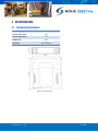
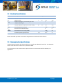
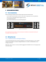
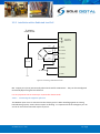
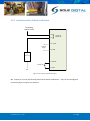
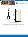
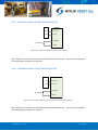
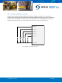
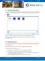
MAXOUT LOAD LIMITER Model MX10x, Version 1+ Installation and User Manual V1.3: 27/01/2015 © CASWA Pty Ltd – 2015 CONTENTS 1 OVERVIEW............................................................................................................................ 4 2 SPECIFICATIONS .................................................................................................................... 5 2.1 Physical Specifications ............................................................................................................ 5 2.2 Electrical Specifications........................................................................................................... 6 2.3 Communication Specifications................................................................................................ 6 3 INSTALLATION DETAILS ......................................................................................................... 7 3.1 Prior to Installation ................................................................................................................. 7 3.2 Wiring Diagrams...................................................................................................................... 7 4 3.2.1 Installation with an existing load display ................................................................. 7 3.2.2 Installation with a Dedicated Load Cell .................................................................... 8 3.2.3 Installation with a 4-20mA Load Output .................................................................. 9 3.2.4 Installation with a 0-10V Load Output ................................................................... 10 3.2.5 Installation with a Q-Link Output (ABUS LIS) ......................................................... 11 3.2.6 Installation with a F-Link Output (ABUS LIS) .......................................................... 11 3.2.7 Setting up Multi-zone Limits .................................................................................. 12 COMMISSIONING DETAILS .................................................................................................. 13 4.1 Installing and Launching the FSU Application ....................................................................... 13 4.1.1 FSU Program Installation........................................................................................ 13 4.1.2 Installing the FSU application ................................................................................. 13 4.1.3 Launching the application ...................................................................................... 13 4.2 Connecting to the Device ...................................................................................................... 14 4.3 Managing Firmware .............................................................................................................. 14 4.4 MaxOut Configuration Screen .............................................................................................. 17 4.4.1 Setting the Crane ID ............................................................................................... 17 4.5 Calibrating the MaxOut ......................................................................................................... 17 4.5.1 Setting the Input Type ............................................................................................ 18 4.5.2 Using/Removing a HoistNet Input ......................................................................... 18 4.5.3 Using the MaxOut with a ControlPro ..................................................................... 19 4.5.4 Checking the Gain .................................................................................................. 20 © CASWA Pty Ltd – 2015 2 | Page 4.5.5 Setting the Zero Value............................................................................................ 21 4.5.6 Calibrating the MaxOut .......................................................................................... 21 4.6 Erasing the Calibration .......................................................................................................... 22 4.7 Configuring One or More Overloads ..................................................................................... 22 4.7.1 Set Overload ........................................................................................................... 22 4.7.2 Overload Sensitivity ............................................................................................... 23 4.7.3 Invert Output.......................................................................................................... 23 4.8 Changing the Gain ................................................................................................................. 23 4.9 Logging Overloads (Firmware 1.8 onwards) ......................................................................... 25 4.9.1 Sending Alerts ........................................................................................................ 25 4.10 Running CheckIt Diagnostics ................................................................................................. 26 5 ROUTINE MAINTENANCE .................................................................................................... 27 6 TROUBLESHOOTING ............................................................................................................ 28 APPENDIX A: COMMUNICATION PROTOCOL ............................................................................... 29 APPENDIX B: FSU SYSTEM REQUIREMENTS ................................................................................. 31 © CASWA Pty Ltd – 2015 3 | Page 1 OVERVIEW MaxOut is an inexpensive electronic load limiter for a single hoist that also wirelessly transmits the load signal using Sole Digital's HoistNet technology. In addition to performing its load limiting function, MaxOut is a HoistNet compatible device that can act as a wireless source of load data for displays, data loggers and load summation units. When used in this configuration, only the source MaxOut device wired to the load cell needs to be calibrated. © CASWA Pty Ltd – 2015 4 | Page 2 SPECIFICATIONS 2.1 Physical Specifications Overall length (mm): 115 Overall width (mm): 100 Overall height (mm): 23 Weight (kg): Mounting: 0.12 30mm DIN Rail Figure 1: Case Dimensions © CASWA Pty Ltd – 2015 5 | Page 2.2 Electrical Specifications Parameter Description Min Vin Supply voltage 32 Iin Supply current 7 Lmax Maximum voltage on a load sensing pin with respect to device gnd Lfs Load pin differential input for full scale reading Max Units 250 VAC 12 mA 7 V 25 mV Vfault Max voltage for fault output 250 V AC Ifault Max current sink by fault output 4 A Pfault Max contactor inrush rating at 48V 200 Allowable operating temperature 20 -40 Typ 8 23 85 W Note1 °C Note1: Extended operation at maximum temperature will reduce the life the device. 2.3 Communication Specifications Communications between the device and a host is usually via a Bluetooth radio link. The Bluetooth device name will be set to the Crane ID, the PIN is 0000. For more details on the communication protocol used to communicate with the MaxOut, see Appendix A. © CASWA Pty Ltd – 2015 6 | Page 3 INSTALLATION DETAILS 3.1 Prior to Installation Before installing your MaxOut device visually inspect the device and check that: 5 6 7 8 1 2 3 4 16 15 14 13 the type of input marked on the front of the device is appropriate for your application; the case is not damaged and fits together securely; terminals are secure; terminal numbering is as per the following diagram. 12 11 10 9 (a) (b) (c) (d) Figure 2: Terminal Positions NB: As each block of 4 terminals can be removed (for installation) it is important that they be reinstalled in the positions shown. 3.2 Wiring Diagrams 3.2.1 Installation with an existing load display The recommended method for connecting a MaxOut to an existing load display is to use a 4-20mA output from the display to a 4-20mA configured MaxOut or to insert a 4-20mA MaxOut into an existing current loop. Where this is not an option, it may be possible to piggyback the MaxOut onto the strain gauge inputs of the load display. © CASWA Pty Ltd – 2015 7 | Page 3.2.2 Installation with a Dedicated Load Cell To existing control circuit MAXOUT 13: 14: Red Green Load limit 250VAC 4A 9: +XCite 10: +Sense 11: -Sense White UP CONTACTOR 12: -XCite Black 2: 240VAC 32-240V AC 1: 0VAC 0V Figure 3: Connecting a dedicated load cell NB: Output pins (13-14) are Normally Closed and rated for 250V AC 4A. They can be reconfigured to Normally Open using the FSU software. It is very important not to connect pin 15,16 to the chassis earth! 3.2.2.1 Connecting the negative reference The MaxOut input circuit is connected to the chassis ground. When installing against an existing load Indicating system, ensure that its inputs are floating. It is important that the voltage on pins 10 and 11 do not exceed 3.3V with respect to pin 12. © CASWA Pty Ltd – 2015 8 | Page 3.2.3 Installation with a 4-20mA Load Output To existing control circuit MAXOUT 13: 14: Load limit 250VAC 4A 10: mA IN 4-20mA Signal 12: GND UP CONTACTOR 2: 240VAC 32-240V AC 1: 0VAC 0V Figure 4: Connecting a 4-20mA load signal NB: Output pins (13-14) are Normally Closed and rated for 250V AC 4A. They can be reconfigured to Normally Open using the FSU software. © CASWA Pty Ltd – 2015 9 | Page 3.2.4 Installation with a 0-10V Load Output To existing control circuit MAXOUT 13: 14: Load limit 250VAC 4A 10: V IN 0-10V Signal 12: GND UP CONTACTOR 2: 240VAC 32-240V AC 1: 0VAC 0V Figure 5: Connecting to a 0-10V Load Signal NB: Output pins (13-14) are Normally Closed and rated for 250V AC 4A. They can be reconfigured to Normally Open using the FSU software. © CASWA Pty Ltd – 2015 10 | Page 3.2.5 Installation with a Q-Link Output (ABUS LIS) LIS F1/F2 Gnd MAXOUT 10: F-Link 12: Gnd 2: 240VAC 32-240V AC 1: 0VAC Figure 6: Connection to an ABUS LIS using a Q-Link ‘Q’ Output NB: Output pins (13-14) are Normally Closed and rated for 250V AC 4A. They can be reconfigured to Normally Open using the FSU software. 3.2.6 Installation with a F-Link Output (ABUS LIS) LIS Q Gnd MAXOUT 10: Q-Link 12: Gnd 2: 240VAC 32-240V AC 1: 0VAC Figure 7: Connecting to an ABUS LIS using the Q-Link Frequency (F1/F2) Output NB: Output pins (13-14) are Normally Closed and rated for 250V AC 4A. They can be reconfigured to Normally Open using the FSU software. © CASWA Pty Ltd – 2015 11 | Page 3.2.7 Setting up Multi-zone Limits MaxOut can be used to implement different load limits in different locations, or in response to external signals. Usually used for altering the maximum allowable load when the crane is moved into specific zones (up to 6 different zones are currently available). These are triggered by zone inputs switches being activated by a set of dry contacts and only for the duration of activation. 3: Zone 2 4: Zone 3 5: Zone 4 6: Zone 5 8: Zone 6 ZONE LIMITS 0V 15: 0 Volts Figure 8: Wiring up individual zone limits © CASWA Pty Ltd – 2015 12 | Page 4 COMMISSIONING DETAILS MaxOut is designed to be commissioned using a laptop computer. You will need a CASWA LINK-2 Bluetooth Modem and the Field Service Utility (FSU) software application loaded on a laptop. 4.1 Installing and Launching the FSU Application 4.1.1 FSU Program Installation Ensure that your computer is switched on, connected to the internet and that the minimum required software versions are installed (see Appendix B for minimum system requirements). Ensure that the LINK-2 modem is installed and that the drivers have loaded. 4.1.2 Installing the FSU application The latest LINK-2 FSU software (Link-2_FSU) can be downloaded from http://www.soledigital.com.au/Link2.html. You should check this location periodically for updates. 4.1.3 Launching the application Double click on the FSU program icon: © CASWA Pty Ltd – 2015 . 13 | Page 4.2 Connecting to the Device The FSU will scan for Bluetooth enabled devices. This process takes approximately 10 seconds, when complete a list of all Sole Digital devices within range will be displayed. MaxOut units are depicted by a icon. If a particular MaxOut unit is not found, ensure it is powered up and press the button to repeat the search. Select the MaxOut you wish to configure by double clicking on the icon. NB: The Bluetooth link between the Laptop using a Link-2 and a MaxOut has a range of approximately 100m. 4.3 Managing Firmware If you running an older version of the FSU application on your laptop then you should update this before continuing. The process for updating the firmware on your Sole Digital device has changed. Firmware should only be updated if you: a) specifically want a new feature that is only available in later versions; b) are experiencing a problem that has been rectified by a later version; c) are experiencing a problem and need to roll back to an earlier firmware version that didn't cause the problem you are experiencing; or d) have been specifically instructed to do so by your MaxOut supplier. © CASWA Pty Ltd – 2015 14 | Page To check for new firmware versions or to access old firmware versions, return to the Device Display screen and right click the desired equipment icon. Select 'Manage Firmware'. A new window will popup and show the FSU software connecting to the device. When this is complete, the window will show the name of the device, its current firmware version and a list of newer firmware that is available for the device. If you need to roll back to an earlier version, check the 'Show old versions' box in the lower left corner of the window. Select a firmware version and then press the <Apply firmware> button that appears in the lower right corner of the window: © CASWA Pty Ltd – 2015 15 | Page The display will change to the following: As the message states, DO NOT switch off the MaxOut or the computer running the FSU software, or remove the Link2 modem until you are told to do so. If either device loses power then the MaxOut may become unusable and the device will need to be returned to your supplier for repair. When the firmware has finished updating successfully you will see a popup window and also be told to power cycle the device before reconnecting: message in the Close this window, wait for the manage firmware window to close (this may take 20 seconds) and power cycle the device as instructed. You will be returned to the first FSU screen, Manage Connections. Wait a few seconds after power cycling the device and then select the device you wish to connect to by double clicking the device. © CASWA Pty Ltd – 2015 16 | Page 4.4 MaxOut Configuration Screen Once the firmware version has been verified, the following screen will appear. This screen shows the: Crane ID (see section 4.4.1 for configuring this) Current firmware version operating on the device It also contains a button (checkbox in lower left corner) to initiate CheckIt diagnostics. This is described in Section 4.9. 4.4.1 Setting the Crane ID To set the crane ID click on the <General> button to return to the first screen. Type in the desired Crane identification in the ‘ID’ field. This must be 18 characters or less. 4.5 Calibrating the MaxOut If your MaxOut device has been preconfigured (only available with Q-Link inputs) or you are using a HoistNet load signal (which is calibrated) then you will not need to calibrate the MaxOut. All other types of MaxOut must be calibrated. Unless you are connecting the device to a Konecranes ControlPro (and elect to use the already calibrated ControlPro settings), this process will require test weights. Click on the Load tab to bring up the load settings screen. © CASWA Pty Ltd – 2015 17 | Page 4.5.1 Setting the Input Type Make sure that the Input is set to the type of MaxOut input. By default, the mV/mA/V input will be selected. This is applicable for MaxOut devices that have a strain gauge, 4-20mA and 0-10V DC input. If you have a Q-Link or Frequency MaxOut (i.e. connected to an ABUS LIS unit) then you will need to change this selection. If you intend to use the MaxOut with a Konecranes ControlPRO make sure that you have selected the <mV,mA,V> input. 4.5.2 Using/Removing a HoistNet Input MaxOut devices are now compatible with CASWA HoistNet. This means that they can obtain their load signal wirelessly from any other HoistNet enabled device, eliminating the need for long cable runs between the load cell and data logger. To receive a load signal via HoistNet, select the HoistNet input and then press the <Bind> button: NB: HoistNet was first enabled in FSU version 10.7. If you do not see the HoistNet option, then you are running an old FSU version. Download and reinstall the lastest version of CASWA FSU. You may also need to update the firmware on your MaxOut. © CASWA Pty Ltd – 2015 18 | Page A box will appear asking you which HoistNet enabled device you want to connect to: Select the device that has the load signal to be used and press <OK>. The popup box will close. The name of the bound HoistNet device will be shown on the Load screen. The connection status will also be shown: NB: You will need to ensure that the originating HoistNet load signal has been calibrated correctly. To unbind a MaxOut from a HoistNet device, or to change the bound device, press the <Bind> button on the Load screen and then select <Unbind> on the popup box. 4.5.3 Using the MaxOut with a ControlPro If your MaxOut device is connected to a Konecranes ControlPro and you want to use the calibration settings stored on the ControlPro (rather than calibrating with test weights) press the <Control Pro> button. A dialog box will appear asking you to confirm this action: © CASWA Pty Ltd – 2015 19 | Page Press <OK> to confirm. Another dialog box will appear. Enter the capacity of the hoist in tonnes and press <OK>. Your device is now calibrated and you will not need to zero or calibrate this hoist in order to use this Liftlog. NB: You need to have selected the <mV,mA,V> input type. 4.5.4 Checking the Gain A bar underneath the load display indicates the signal strength. It is important that the highlighted section of the bar moves to the right as load is increased and moves to the left as load is decreased. If the bar does not change at all, check your wiring from the load cell. Also check that you have selected mV,mA,V input type. A small change in the bar across a wide range of loads (e.g. zero to full load) indicates that the load signal requires more gain. © CASWA Pty Ltd – 2015 20 | Page Conversely, if the bar moves past the end of the scale then you have too much gain. The signal from the load cell is being clipped and load readings will be incorrect. The red box around the bar alerts you to this clipping. If this occurs, you need to reduce the gain in the MaxOut. See section 4.8 for instructions on changing the gain. (NB: You will need to recalibrate the MaxOut after changing the gain.) 4.5.5 Setting the Zero Value With no load on the hook (or the crane load display reading 0.00t), click on the <Zero> button. Within a few seconds the display will change to 0.0t: 4.5.6 Calibrating the MaxOut Lift a load (minimum 80% of rated capacity) and click the <Cal> button. Enter the mass shown on the load display when prompted and press <OK>. NB: If the fault output of the logger is used as an overload, you may need to go to the Overload screen and set a large overload limit (e.g. 3000) to allow the load to be lifted. See section 0 for details. Tap the <OK> button and the main screen will now display the load on the hook. © CASWA Pty Ltd – 2015 21 | Page NB: An overload will probably be shown (box becomes red) as the maximum load has not yet been set. 4.6 Erasing the Calibration Under some circumstances, it may be necessary to erase the calibration of a hoist. Warning: IF YOU ERASE THE CALIBRATION THEN YOU WILL NEED A TEST WEIGHT TO SET IT AGAIN (unless you are connected to an LIS via Q-Link or ControlPro)! To reset the calibration for a hoist, tap the <!> button. NB: Resetting the calibration of one hoist (main or aux) does not affect the calibration of the other. 4.7 Configuring One or More Overloads To set the overloads and/or to invert the output signals, press the ‘Overload’ tab to bring up the following screen: MaxOut can be used to set different load limits, usually used for altering the maximum allowable load when the crane is moved into specific zones (up to 6 different zones are currently available). These are triggered by input limit switches being activated and only for the duration of activation. For details on wiring up these zones see Section 3.2.7. The crane will be deemed to be operating in Zone 1 (controlled by Limit 1) unless an alternative limit is active. 4.7.1 Set Overload Enter the desired overload in tonnes for each zone. This can be in 0.1t increments (E.g. 9.4). © CASWA Pty Ltd – 2015 22 | Page The current active zone/limit is shown in black. Inactive zones are greyed out but their limit values can still be changed. 4.7.2 Overload Sensitivity The overload sensitivity is controlled by a slider that changes how sensitive the overload is to short overloads caused by signal noise. Moving the slider to the right will make it less sensitive, so that it will effectively take longer to respond to a real overload event. Moving it to the left will make the logger respond quicker to real overloads, but also make it more susceptible spurious trips. You should set this slider as far to the left as possible without the overload tripping during normal operation. A text warning will display if this is set too high. 4.7.3 Invert Output The fault output on the MaxOut is a pair of normally closed contacts. Checking the <Output N/O> box will change the normally closed fault output to normally open. You may need to do this: If there is an interposing relay between the MaxOut and the up contactor; You want the MaxOut to operate in a “fail functional” rather than a “fail safe” mode; You are using the MaxOut for slack rope detection 4.8 Changing the Gain When using a strain gauge load cell, MaxOut can be configured to one of 3 gain settings by moving an internal jumper. To change the gain, remove the internal board from the case. To do this, gently press the tabs on each side of the MaxOut and separate the end with the terminals from the main body. (The board will be Lowest gain: Remove attached to the terminals.) If you have already wired in jumper or move to the MaxOut, remove the four terminal blocks first. one side. Place the jumper into one of the following 3 positions. (A) Position 1 – No jumper or jumper off to one side. In this position, gain is set to the lowest setting, suitable for a 3mV/V load cell at full span. © CASWA Pty Ltd – 2015 23 | Page (B) Position 2 – Jumper bridges lower two terminals. In this position, gain is set to the medium setting, suitable for a 2mV/V load cell at full span. (C) Position 3 – Jumper bridges upper two terminals. In this position, gain is set to the maximum setting, suitable for a 1mV/V load cell at full span. Medium gain: Bridge lower two pins with jumper. Max gain: Bridge upper two pins with jumper. Reinsert the board into the case. If you removed the terminals, replace these too. See section 3.1 for their correct positions. You will need to recalibrate the MaxOut device after changing the gain. © CASWA Pty Ltd – 2015 24 | Page 4.9 Logging Overloads (Firmware 1.8 onwards) From version 1.8 of the MaxOut firmware the device is able to log overloads. To access this information, select the <Logging> tab to bring up the following information: The information that will be logged and is displayed on this screen includes: a) the number of times the load limit has been activated; b) the biggest overload recorded in kg; and c) the size of the most recent overload in kg. These values are calculated from the last time <Reset Counters> was pressed. 4.9.1 Sending Alerts If you have a SiteSentinel on site, the MaxOut can be configured to send an email or SMS to an Australian mobile phone whenever an overload event occurs. To configure alerts, make sure that the SiteSentinel is switched on when you connect to the MaxOut. You should see the following icon in your list of devices when first connecting: © CASWA Pty Ltd – 2015 25 | Page To configure notification enter a single email address or a 10 digit mobile phone number in the <Notify> field: If no Site Sentinel was detected when first connecting to the MaxOut, this field not be visible. To send alerts to multiple addresses or to get a logged history of overloads via the web contact [email protected]. 4.10 Running CheckIt Diagnostics To confirm whether critical settings and parameters have been set sensibly, after completing the setup and commissioning of the MaxOut device, it is strongly recommended that you run CheckIt diagnostics (first introduced in version 11.9 of the FSU application). To initiate CheckIt Diagnostics, go to the General Tab and click on the check box in the lower left corner of the tab: A new window will appear and CheckIt Diagnostics will be initiated. During this process you may be asked to enter parameters (e.g. rated capacity of the hoist) to verify that critical settings have been entered and have saved correctly. Any potential issues or irregularities will be described in the CheckIt Diagnostics window. Press <Close> to return to the main FSU screen. © CASWA Pty Ltd – 2015 26 | Page 5 ROUTINE MAINTENANCE There is no routine maintenance for this device. © CASWA Pty Ltd – 2015 27 | Page 6 TROUBLESHOOTING Fault Cause Fix Load display indicates a fault Logger is affecting load pin voltages Check power to the logger. Disconnect pins 10 and 11 to verify that the logger is causing the fault. Check logger LED is operational (solid red or green). Check that the voltage from pins 11 and 12 is between 4 and 6 volts. If these voltages are out, check the connection between logger GND and load pin GND. Unable to connect to logger from FSU Logger or FSU are busy Power cycle the crane. Incorrect wiring Check that wiring is as per section 3.2. Check that removable terminals have been reinserted into their correct positions as shown in Figure 2. Pluggable terminals not seating correctly. Replace pluggable terminal and rewire the associated terminals. Limit cuts out prematurely on hoisting and adjusting sensitivity has no effect Magnetic interference causing MaxOut to reset Check that MaxOut is at least 15mm from any large contactor. Adding MaxOut to a 420mA current loop causes a fault MaxOut is pulling the loop to GND Ensure the MaxOut is the lowest potential device in the loop or contact CASWA to order a 4-20mA isolator. © CASWA Pty Ltd – 2015 28 | Page APPENDIX A: COMMUNICATION PROTOCOL The host sends single character commands to the device to write or query parameters. Each command must be followed by a carriage return <CR>(ASCII 13). Where the command is a query command, no arguments are sent and the device will respond with a single line (except for the “u” and “E” commands) the requested value in ASCI text followed by a <CR>. Where the command is a set command, an argument may be included between the command and the <CR> . Where numbers are sent or received, they are sent as clear text; eg “1234” Where a number represents a load (eg the “o” and “O”), it is expressed in 100Kg units. Eg 3.5mt would be sent and received as 35. © CASWA Pty Ltd – 2015 29 | Page Communication commands: Command v R/W Read Description Query the firmware version number. ? h Read Read H r Write Read i Read Display a summary of all settings Query the input mode: 0=Analog 1=Q-Link 2=Frequency Set the input mode Query the raw loadpin reading. The lifted load may be computed from this value as (Raw-Zero)/Cal. See the ”C” command. Query the device ID. I Write z Read Z c Write Read C Write on Read On Write wn Read Wn Write * Write © CASWA Pty Ltd – 2015 Set the device ID. Device ID’s are limited to 18 characters Query the zero parameter The zero value is used to calculate the actual load. See the “C”, and “r” commands/ Set the zero parameter. Query the cal parameter. The cal parameter is used to calculate the actual load. See the “C” and “r” commands Set the cal parameter. In normal operation, the cal parameter would be set as follows: Send the “r” command to get the raw reading from the load pin in it’s unloaded state. Send the “Z” command to set the zero parameter Apply a known load to the pin. Send the “r” command to get the raw reading from the load pin. Sent the “C” command to set the calibration value to (Rawunloaded-zero)*Known_Load (in 100Kg units) Query the overload (setpoint) parameter. This parameter is stored in 100Kg units, eg 3.5mt is expressed as 35. It is used by the device to determine when an overload occurs. Set the overload parameter. Example Send:v<CR> Rcv:1.02b<CR> Send:h<CR> Rcv:2<CR> Send:H0<CR> Send:r<CR> Rcv: 354<CR> Send: i<CR> Rcv: crane34<CR> Send: Icrane45<CR> Send: z<CR> Rcv: 34<CR> Send: Z23<CR> Send: c<CR> Rcv: 11<CR> Send: C9<CR> Send: o1<CR> Rcv: 35<CR> Send: O140<CR> Query the inverted status of a setpoint output. A return value of 1 means the output is normally open. Set the inverted status of a setpoint output. Send: w2<CR> Rcv: 1<CR> Send: W20<CR> Reboot the device. This command is usually only used to load new firmware onto the device Send: *<CR> 30 | Page APPENDIX B: FSU SYSTEM REQUIREMENTS The minimum requirements for operating CASWA’s Field Service Utility (FSU) and Link-2 Bluetooth modem are: Laptop computer running Windows XP SP3 or later; One Spare USB port; Microsoft .NET framework 3.5. © CASWA Pty Ltd – 2015 31 | Page