1
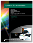
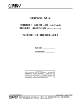
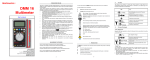
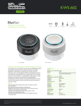
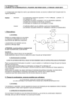
Table of Contents
TITLE
PAGE
1. GENERAL INSTRUCTIONS
…………………………………………………………………………………………….
1
1.1 Precaution safety measures
1.1.1 Preliminary
1.1.2 During use
1.1.3 Symbols
1.1.4 Instructions
…………………………………………………………………………….………………
……………………….…………………………………………………………………....
……………………………………..……………………………………………………...
…………………………………….….…………………………………………………...
………………………………….…………………..………………………………………
1
1
1
3
3
2. DESCRIPTION
………………………………….…………………..………………………………………
4
2.1 Instrument Familiarization
2.2 LCD Display
2.3 Key pad
2.4 Rotary switch
2.5 Terminals
2.6 Accessories
………………………………….…………………..………………………………………
………………………………….…………………..………………………………………
………………………………….…………………..………………………………………
………………………………….…………………..………………………………………
………………………………….…………………..………………………………………
4
5
7
8
8
………………………………….…………………..………………………………………
9
3. FUNCTION DESCRIPTION
3.1 General Functions
3.1.1 DATA HOLD mode
3.1.2 Manual ranging and Autorange mode
3.1.3 Auto power-off / Disable auto power off
3.1.4 MAX/MIN recording mode
3.1.5 Serial data output
3.2 Measurement Functions
3.2.1 Resistance measurement
3.2.2 Capacitance measurement
………………………………….…………………..………………………………………
………………………………….…………………..………………………………………
………………………………….…………………..………………………………………
………………………………….…………………..………………………………………
………………………………….…………………..………………………………………
………………………………….…………………..………………………………………
………………………………….…………………..………………………………………
………………………………….…………………..………………………………………
………………………………….…………………..………………………………………
………………………………….…………………..………………………………………
10
10
10
10
10
11
11
12
12
13
Ⅰ
6000 COUNTS DIGITAL LCR METER
USER'S MANUAL
TITLE
3.2.3 Inductance measurement
PAGE
………………………………….…………………..………………………………………
14
4. TECHNICAL SPECIFICATIONS
………………………………….…………………..………………………………………
15
4.1 General specifications..
4.2 Measurement specifications
4.2.1 Resistance
4.2.2 Capacitance
4.2.3 Inductance
………………………………….…………………..………………………………………
………………………………….…………………..………………………………………
………………………………….…………………..………………………………………
………………………………….…………………..………………………………………
………………………………….…………………..………………………………………
15
16
16
16
17
5. MAINTENANCE
………………………………….…………………..………………………………………
18
5.1 General maintenance
5.2 Fuse replacement
5.3 Battery replacement
………………………………….…………………..………………………………………
………………………………….…………………..………………………………………
………………………………….…………………..………………………………………
18
18
19
6. RS232 interface (optional software)
………………………………….…………………..………………………………………
20
6.1 Welcome
………………………………….…………………..………………………………………
20
6.2 System Requirements
………………………………….…………………..………………………………………
20
6.3 Installation
………………………………….…………………..………………………………………
20
6.4 Connect
………………………………….…………………..………………………………………
20
6.5 Operation
………………………………….…………………..………………………………………
20
6.6 Interface Setting
………………………………….…………………..………………………………………
20
6.7 Sampling Time
………………………………….…………………..………………………………………
20
6.8 Main Interface
………………………………….…………………..………………………………………
21
Ⅱ
GENERAL INSTRUCTIONS
1. GENERAL INSTRUCTIONS
The meter is a hand-held, battery-operator instrument for testing inductance, capacitance and resistance. If this device is damaged or something is
missing, contact the place of purchase immediately.
This instrument complies with the specifications set out in the IEC 61010-1, 2001, publication concerning safety requirements for electronic measuring
apparatus.
This manual contains information and warnings must be followed to ensure safe operation as well as to maintain the meter in a safe condition.
To get the best service from this instrument, read carefully this user's manual and respect the detailed safety precautions.
1.1 Precautions safety measures
1.1.1 Preliminary
* The meter is safety-certified in compliance with EN61010 (IEC 1010-1) Installation Category II (CAT. II) 50V, Pollution Degree 2 environment.
* When using this Multimeter, the user must observe all normal safety rules concerning:
― protection against the dangers of electric current.
― protection of the Multimeter against misuse.
* For your own safety, only use the test probes supplied with the instrument. Before use, check that they are in good condition.
1.1.2 During use
* Use the meter only as specified in this manual; otherwise, the protection provided by the meter may be impaired.
* Do not use the meter or test leads if they look damaged.
* If the meter is used near noise generating equipment, be aware that display may become unstable or indicate large errors.
* Use extreme caution when working around bare conductors or bus bars.
1
6000 COUNTS DIGITAL LCR METER
USER'S MANUAL
* Do not operate the meter around explosive gas, vapor, or dust.
* The instrument that used in dusty environment should be wiped and cleaned regularly.
* Check the main function dial and make sure it is at the correct position before each measurement.
* When the range of the value to be measured is unknown, check that the range initially set on the meter is the highest possible or, wherever possible,
choose the autoranging mode.
* To avoid damages to the instrument, do not exceed the maximum limits of the input values shown in the technical specification tables.
* When measuring within a circuit, the circuit must be de-energized before connecting the test leads.
* When making connections, connect the common test lead before connecting the live test lead; when disconnecting, disconnect the live test lead
before disconnecting the common test lead.
* Before changing functions, disconnect the test leads from the circuit under test.
* When measuring in-circuit components, first de-energize the circuits before connecting to the test leads.
* Discharge capacitor before testing.
* Never perform resistance measurements on live circuits.
* Disconnect circuits power and discharge all high-voltage capacitors or inductances before testing resistance, inductance or capacitance.
* Change the battery when the
2
symbol appears to avoid incorrect data.
GENERAL INSTRUCTIONS
1.1.3 Symbols:
Symbols used in this manual and on the instrument:
Caution: refer to the instruction manual. Incorrect use may result in damage to the device or its components.
Fuse
Conforms to European Union directives
1.1.4 Instructions
* Before opening up the instrument, always disconnect from all sources of electric current and make sure you are not charged with static electricity,
which may destroy internal components.
* Any adjustment, maintenance or repair work carried out on the meter while it is live should be carried out only by appropriately qualified personnel,
after having taken into account the instructions in this present manual.
* A "qualified person" is someone who is familiar with the installation, construction and operation of the equipment and the hazards involved. He is
trained and authorized to energize and de-energize circuits and equipment in accordance with established practices.
* When the instrument is opened up, remember that some internal capacitors can retain a dangerous potential even after the instrument is switched off.
* Do not leave the instrument exposed to direct heat from the sun or beat source for long periods.
* Before removing the cover, ensure that the instrument is disconnected from any circuit and in power "OFF" position.
* If any faults or abnormalities are observed, take the instrument out of service and ensure that it cannot be used until it has been checked out.
* If the meter is not going to be used for a long time, take out the battery and do not store the meter in high temperature or high humidity environment.
3
6000 COUNTS DIGITAL LCR METER
USER'S MANUAL
2. DESCRIPTION
2.1 Instrument Familiarization
LCR DIGITAL METER
WAKE
RS232
HOLD
①Serial data output connector
②LCD display
ON
OFF
60mH
600mH 6H
6mH
600 uH
H mH uH
4
③Keypad
60H
④Rotary switch
⑤Terminals
DESCRIPTION
2.2 LCD Display
See Table 1 indicated for information about the LCD display.
Figure 1.Display
5
6000 COUNTS DIGITAL LCR METER
USER'S MANUAL
Table 1. Display Symbols
Number
Symbol
Meaning
Serial data output is active.
1
The battery is low.
2
Warning: To avoid false readings, which could lead to possible electric shock or personal injury,
replace the battery as soon as the battery indicator appears.
3
Auto power-off is enabled
4
The Meter is in the Autorange mode in which the meter automatically selects the range with the best resolution.
5
The Meter is in the Manual ranging mode
6
The Meter is in the Data Hold mode
7
Maximum reading displayed
Minimum reading displayed
8
9
10
11
12
6
nF, µF, mF
µH, mH, H
Ω, kΩ, MΩ
F:
Farad. The unit of capacitance.
mF:
Millifarad. 1x10⁻³ or 0.001 farads.
µF:
Microfarad.1x10-6 or 0.000001 farads.
nF:
Nanofarad. 1x10⁻⁹ or 0.000000001 farads.
H:
Henry. The unit of inductance.
mH:
Millihenry. 1x10⁻³ or 0.001 henries.
µH:
Microhenry.1x10-6 or 0.000001 henries.
Ω:
Ohm. The unit of resistance.
kΩ:
Kilohm. 1x10 or 1000 ohms.
MΩ:
Megohm. 1x10 or 1,000,000 ohms.
3
6
The input is too large for the selected range.
DESCRIPTION
2.3 Keypad
See Table 2 indicated for information about the keypad operations.
Table 2. Keypad
Key
Function
Operation performed
ON/OFF (green)
Any switch position
turn the meter on or off
RS232
Any switch position
Press RS232 to enable and disable serial data output.
MANUAL/WAKE
Ω and
1. Selection of the autorange (default) or manual ranging mode: short press < 1 sec. on the
key, the beep sounds briefly.
2. Switch from manual ranging to autorange mode: long press > 1 sec. on the key, the beep
sounds briefly.
3. In manual mode, ranges selection: press successively < 1 sec. on the key.
HOLD
MAX/MIN
Sleep mode
Re-power the meter on.
Any switch position
Press HOLD to enter and exit the Data Hold mode.
MAX MIN recording
Stops and starts recording without erasing recorded values.
Any switch position
Starts recording of maximum and minimum values.
7
6000 COUNTS DIGITAL LCR METER
USER'S MANUAL
2.4 Rotary switch
See Table 3 indicated for information about the rotary switch positions.
Table 3. Rotary Switch Positions
Switch Position
Ω
Function
12
Capacitance measurement
13
600µ
µH
Inductance measurements from 0.1µH to 600µH.
14
6mH
Inductance measurements from 600µH to 6mH.
14
60mH
Inductance measurements from 6mH to 60mH.
14
600mH
Inductance measurements from 60mH to 600mH.
14
6H
Inductance measurements from 600mH to 6H.
14
60H
Inductance measurements from 6H to 60H.
14
2.5 Terminals
See Table 4 indicated for information about the terminals.
Table 4. Terminals
Terminal
Ω
Description
Red terminal receiving the red clip for resistance and capacitance measurements.
Black terminal receiving the black clip as a common reference.
H mH µH
8
Page
Resistance measurement
Terminals receiving the leads for Inductance measurement.
DESCRIPTION
2.6 Accessories
Delivered with the multimeter:
∞ User's manual
………………………………………………………………………..
One piece
∞ Test clips
………………………………………………………………………..
One piece
∞ Carry case
………………………………………………………………………..
One piece
Optional:
∞ Multi function socket
………………………………………………………………………..
One piece
∞ RS232 interface line
………………………………………………………………………..
One piece
∞ RS232 software
………………………………………………………………………..
One piece
9