
1
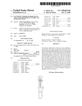
US008654120B2
(12) United States Patent
(10) Patent N0.:
(45) Date of Patent:
Beaver, III et al.
(54)
VISUALIZINGA CUSTOM PRODUCT IN SITU
(75)
Inventors: Robert Irven Beaver, III, San
Francisco, CA (US); Leslie Young
Harvill, Half Moon Bay, CA (US);
Richard Harold Bean, Cupertino, CA
2003/0080978 A1*
2004/0017595
2004/0133081
2005/0226498
2005/0258234
A1
A1
A1
A1
5/2003
US 8,654,120 B2
Feb. 18, 2014
Navab et al. ................ .. 345/633
1/2004
7/2004
10/2005
11/2005
Ikeda
Teller et a1.
Lee
Silverbrook et al.
(Continued)
(Us)
FOREIGN PATENT DOCUMENTS
(73) Assignee: Zazzle.com, Inc., Redwood City, CA
(Us)
Notice:
Subject to any disclaimer, the term of this
patent is extended or adjusted under 35
EP
EP
W0
1 124 200 A2
1365 358 A2
WO 2009/094724 A1
OTHER PUBLICATIONS
U.S.C. 154(b) by 0 days.
Hirokazu Kato and Mark Bilinghurst. ARToolkit User Manual.
(21) Appl. No.: 13/604,059
(22) Filed:
Human Interface Technology Lab, University of Washington, 2000 .*
Sep. 5, 2012
(65)
1/2001
11/2003
8/2009
(Continued)
Prior Publication Data
US 2013/0050205 A1
Primary Examiner * David T Welch
Feb. 28, 2013
Assistant Examiner * Jin Ge
Related US. Application Data
(74) Attorney, Agent, or Firm * Hickman Palermo Truong
(63)
Continuation of application No. 13/ 539,788, ?led on
Jul. 2, 2012.
(60) Provisional application No. 61/529,883, ?led on Aug.
31, 201 1.
(51)
(52)
Int. Cl.
G06T 15/00
US. Cl.
USPC
(58)
(2011.01)
........................................................ ..
345/419
Field of Classi?cation Search
USPC
........................................................ .. 345/419
See application ?le for complete search history.
(56)
References Cited
Becker Bingham Wong LLP
(57)
ABSTRACT
Techniques are described for visualizing a product at the
actual location in the environment at Which the product is to
be used or displayed. An embodiment of the approaches
described herein may be used in the context of a computer
based system that can receive and store digital images,
receive a request to manufacture a custom framed product
including an identi?cation of an image to be framed and a
type of mat and/or frame, and display a previeW image of the
custom framed product that simulates the actual appearance
of the product as closely as possible. With such a system, the
U.S. PATENT DOCUMENTS
6,591,011 B1*
8,090,461 B2
8,174,521 B2
2001/0034668 A1
7/2003
Nielsen ....................... .. 382/218
previeW image may be highly realistic under idealized light
ing and display conditions.
1/2012 Ohiaeri et al.
5/2012 Harvill et al.
10/2001 Whitworth
26 Claims, 7 Drawing Sheets
STORAG E
DEVICE
MAIN
MEMORY
DISPLAY
ma
501
SERVER
m
INPUT DEVICE
I
I
I
I
I
CURSOR
CONTROL
r111
I
I
I
I
I
PROCESSOR
COMMUNICATION
INTERFACE
NETWORK
US 8,654,120 B2
Page 2
(56)
Nima Soltani, Mehmet Yilmax, “Using Augrnented-Reality on Pla
nar Surfaces for Previewing Décor Changes”. Stanford University
EE368 Class Project Spring 2010.*
References Cited
U.S. PATENT DOCUMENTS
Pantida Patirupanusara, “Marker-Based Augmented Reality Magic
2006/0197775 A1
2007/0067179 A1
9/2006 Neal
3/2007 Kerr et al.
Book for Anatomical Education”, International Conference on Com
2007/0098234 A1*
5/2007
2007/0124215 A1
5/2007 Simmons
2007/0143082 A1
6/2007 Degnan
2008/0069451 A1*
3/2008
2008/0247674 A1*
10/2008
Walch .... ..
2008/0285854 A1*
11/2008
Kotake et al. ............... .. 382/190
2009/0109214 A1
2009/0177551 A1
Fiala ........................... .. 382/120
Ikeda .......................... .. 382/199
. 382/305
4/2009 Harvill et al.
7/2009 Cue et al.
Ryu et al. .................... .. 345/419
Douris et al. ............... .. 345/630
puter and Communication Technologies (ICCCT’2012) May 26-27,
2012 Phuket.*
Paul L. Rosin, “Training Cellular Automata for Image Processing”,
SCIA 2005, LNCS 3540, pp. 195-204, 2005*
Omar Choudary, Vincent Charvillat, Romulus Grigoras, and Pierre
Gurdjos, “MARCH: Mobile Augmented Reality for Cultural Heri
tage”, MM’09, Oct. 19-24, 2009, Beijing, China.*
Pakemon AR Marker in Sep. 2001 (http://wwwpokemastersnet/
2009/0195538 A1*
2009/0289955 A1*
8/2009
11/2009
2009/0317010 A1
12/2009 Gerhard et a1.
“AR tool lets you bring home a virtual Sony Bravia” dated Aug. 29,
2009/0324100 A1*
12/2009
2011 (1 page).
Kletter et al. ............... .. 382/217
forums/showthread.php?t:24845).*
2010/0036753 A1
2/2010 Harvill et al.
Schalkoff R. J ., “Syntactic Pattern Recognition (Syntrp) Overview”,
2010/0048290 A1*
2010/0066750 A1*
2/2010 Baseley et a1. ................ .. 463/25
3/2010 Yu et a1.
. 345/581
Pattern Recognition: Statistical, Structural ad Neural Approaches,
Wiley, 68 pages.
European Patent Of?ce, “Of?ce Action”, in application No.
2010/0092079 A1*
4/2010
2010/0106283 A1
2010/0185309 A1
4/2010 Harvill et al.
7/2010 Ohiaeri et al.
2010/0185529 A1*
7/2010
Chesnut et al. ............... .. 705/27
2010/0189316 A1*
7/2010
Walch .......... ..
2010/0238166 A1*
9/2010 Tamstorf et al.
2010/0287511 A1*
2011/0098837 A1
2011/0280447 A1*
11/2010
Aller ........................... .. 382/165
. 382/125
12181208.5-1238, dated Dec. 6, 2012, 7 pages.
Current Claims in application No. 12181208.5-1238, dated Dec.
2012, 4 pages.
. 345/420
U.S. Appl. No. 13/604,059, ?led Sep. 5, 2012, Of?ce Action, Jan. 2,
Meier et al. ................. .. 715/848
4/2011 Yucel et al.
11/2011
Conwell ..................... .. 382/103
2013.
US. Appl. No. 13/539,788, ?led Jul. 2,2012 Of?ce Action, Jan. 17,
2011/0292451 A1
12/2011 Harvill
2013.
2011/0305368 A1*
12/2011
Osako ......................... .. 382/103
US. Appl. No. 12/790,711, ?led May 28,2010, Of?ce Action, Jan. 3,
2012/0218300 A1*
8/2012
Hayakawa .................. .. 345/633
2013/0057549 A1
2013/0060801 A1
3/ 2013 Beaver et al.
3/ 2013 Beaver et al.
OTHER PUBLICATIONS
HirokaZu Kato and Mark Billinghurst. Marker tracking and hmd
calibration for a videobased augmented reality conferencing system.
In Proceedings of the 2nd International Workshop on Augmented
Reality (IWAR 99), San Francisco, USA, Oct. 1999.*
Mark Fiala. Artag, a ?ducial marker system using digital techniques.
In CVPR ’05: Proceedings of the 2005 IEEE Computer Society
Conference on ComputerVision and Pattern Recognition (CVPR’05)
2:590-596. IEEE Computer Society, 2005*
Ryan A. Beasley, “SemiautonomousMedical Image Segmentation
Using Seeded Cellular Automaton Plus Edge Detector”, Interna
tional Scholarly Research Network ISRN Signal Processing vol.
2012, Article ID 914232, 9 pages.*
Daniel Wagner, Tobias LanglotZ, and Dieter Schmalstieg. Robust and
unobtrusive marker tracking on mobile phones. In ISMAR ’08: Pro
ceedings of the 7th IEEE/ACM International Symposium on Mixed
and Augmented Reality, pp. 121-124, Washington, DC, USA, 2008.
IEEE Computer Society.*
Johannes Kohler, Alain Pagani, and Didier Stricker, “Detection and
Identi?cation Techniques for Markers Used in Computer Vision”,
Digital Object Identi?er 10.4230/0ASIcs.VLUDS.2010.36.*
Homayoun Bagherinia o Roberto Manduchi, “Robust real-time
detection of multi-color markers on a cell phone”, J Real -Time Image
Proc., Jun. 3, 2011.*
Jun Rekimoto, “Matrix: A Realtime Object Identication and Regis
tration Method for Augmented Reality”, Computer Human Interac
tion, 1998. Proceedings. 3rd Asia Paci?c, Jul. 15-17, 1998, pp.
63-68.*
2013.
HirokaZu Kato and Mark Billnghurst. “ARToolkit User Manual”,
Human Interface Technology Lab, University of Washington, dated
2000, 44 pages.
HirokaZu Kato and Mark Billinghurst. “Marker Tracking and HMD
Calibration for a Videobased Augmented Reality Conferencing Sys
tem”, In Proceedings of the 2nd International, Workshop on Aug
mented Reality (IWAR 1999), San Francisco, USA Dated Oct. 1999,
10 pages.
Mark Fiala, “Artag, A Fiducial Marker System Using Digital Tech
niques”, In CVRP ’05: Proceedings of the 2005 IEEE Computer
Society Conference on Computer vision and Pattern Recognition
(CVPR) 2:590-596. IEEE Computer Society, dated 2005, 7 pages.
Ryan A. Beasley, “Semiautonomous Medical Image Segmentation
Using Seeded Cellular Automation Plus Edge Detector”, Interna
tional Scholarly Research Network ISRN Signal Processing Volume,
dated 2012, Article ID 914232, 9 pages.
Daniel Wagner, Tobias LanglotZ, and Dieter Schmalstieg, “Robust
and Unobtrusive Marker Tracking on Mobile Phones”, In ISMAR
’08: Proceedings of the 7th IEEE/ACM International Symposium on
Mixed and Augmented Reality, Washington, DC, USA, Dated 2008,
IEEE Computer Society, 4 pages.
Johannes Kohler, Alain Pagani, and Didier Stricker, “Detection and
Identi?cation Techniques for Markers Used in Computer Vision”,
Digital Object Identi?er 10.4230/OASics. VLUDS.2010.36, dated
2010, 9 pages.
Homayoun Bagherinia O Roberto Manduchi, “Robust Real-Time
Detection of Multi-Color Markers on a Cell Phone”, J Real-Time
Image Proc., Dated Jun. 3, 2011, 17 pages.
Jun Rekimoto, “Matrix: A Realtime Object Identication and Regis
tration Method for Augmented Reality”, Computer Human Interac
tion, Dated 1998, Proceedings, 3rd Asia Paci?c, Jul. 15-17, 1998, 6
pages.
Jun Rekimoto and Yuji Ayatsuka, “CyberCode: Designing Aug
Jun Rekimoto and Yuji Ayatsuka, “CyberCode: Designing Aug
mented Reality Environments with Visual Tags”, Proceedings of
mented Reality Environments with Visual Tags”, Proceedings of
DARE 2000 on Designing, Dated Apr. 2000, 10 pages.
DARE 2000 on Designing, Apr. 2000.*
Martin HirZer, “Marker Detection for Augmented Reality Applica
tions”, GraZ University of Technology, Austria, Dated Oct. 27, 2008,
Martin HirZer, “Marker Detection for Augmented Reality Applica
tions”, GraZ University of Technology, Austria, Oct. 27, 2008.*
W. Lee and W. Woo, “Real-time Color Correction for Marker-based
27 pages.
W. Lee and W. Woo, “Real-time Color Correction for Marker-Based
Augmented Reality Applications,” International Workshop on Ubiq
Augmented Reality Applications”, International Workshop on Ubiq
uitous VR (IWUVR2009), pp. 32-55, 2009*
uitous VR (IWUVR2009), dated 2009, 4 pages.
US 8,654,120 B2
Page 3
(56)
References Cited
OTHER PUBLICATIONS
Nima Soltani, Mehmet Yilmax, “Using Augmented-Reality on Pla
nar Surfaced for Previewing Décor Changes”, Stanford University
EE368 Class Project Spring, dated 2010, 5 pages.
Pantida Patirupanusara, “Marker-Based Augmented Reality Magic
Book for Anatomical Education”, International Conference on Com
puter and Communication Technologies (ICCCT’2012) May 26-27,
2012, Phuket, 3 pages.
Paul L. Rosin, “Training Cellular Automata for Image Processing”,
SCIA 2005, LNCS 3540, dated 2005, 10 pages.
Omar Choudary, Vincent Charvillat, Romulus Grigoras, and Pierre
Gurdjos,“MARCH: Mobile Augmented Reality for Cultural Heri
tage”, MM’09, Dated Oct. 19-24, 2009, Beijing, China, 2 pages.
Pakemon AR Marker in Sep. 2001 (http://pol<emasters.net/forums/
showthread.php?t:24845) 17 pages.
Zhang et al., “Visual Marker Detection and Decoding in AR Systems:
A Comparative Study”, IEEE, dated 2002, 10 pages.
Internatioanal Searching Authority, “Search Report”, in application
No. PCT/2012/053536, dated Nov. 9, 2012, 10 pages.
Current Claims PCT/2012/053536, dated Nov. 2012, 5 pages.
International Searching Authority, “Search Report” in application
No. PCT/US12/53535, dated Feb. 5,2013, 12 pages.
Current Claims in application No. PCT/US12/53535, dated Feb.
2013, 5 pages.
U.S. Appl. No. 13/539,788, ?led Jul. 2, 2013, Final Of?ce Action,
Jun. 5, 2013.
* cited by examiner
US. Patent
Feb. 18, 2014
Sheet 1 017
US 8,654,120 B2
2:H
US. Patent
Feb. 18, 2014
Sheet 2 of7
US 8,654,120 B2
\210
FIG.
2
US. Patent
Feb. 18, 2014
Sheet 3 of7
US 8,654,120 B2
US. Patent
Feb. 18, 2014
Sheet 4 of7
wow
N?H
m?H
.GE<<
US 8,654,120 B2
US. Patent
Feb. 18, 2014
Sheet 5 of7
2;H
6Emw
US 8,654,120 B2
asI/,
US. Patent
Feb. 18, 2014
Sheet 6 of7
>
Sm/
.QE
m
US 8,654,120 B2
>
US 8,654,120 B2
1
2
VISUALIZING A CUSTOM PRODUCT IN SITU
be applied and speci?es various parameter values relating to
the product such as color, siZe, image placement location, or
CROSS REFERENCE TO RELATED
APPLICATIONS
others. The server computer or terminal generates a rendered
image shoWing hoW the product Will appear after custom
manufacture With the speci?ed image applied. The user
approves the rendered image and places an order for the
product. A manufacturer receives the order data, manufac
This application claims under 35 U.S.C. § 120 the bene?t as
a Continuation of application Ser. No. 13/539,788, ?led Jul.
2, 2012, Which claims the bene?t under 35 U.S.C. §119(e) of
tures the product as speci?ed and provides the custom manu
factured product to the user.
Provisional Application No. 61/529,883, ?led Aug. 31, 2011,
the entire contents of each of Which is hereby incorporated by
reference as if fully set forth herein. The applicant(s) hereby
rescind any disclaimer of claim scope in the parent applica
tion(s) or the prosecution history thereof and advise the
USPTO that the claims in this application may be broader
than any claim in the parent application(s).
This application is related to US. application Ser. No.
11/925,716, ?led Oct. 26, 2007, US. application Ser. No.
12/257,016, ?led Oct. 23, 2008, and US. application Ser. No.
12/546,582, ?ledAug. 24, 2009, the entire contents of each of
Which are hereby incorporated by reference for all purposes
One type of product of interestinot offered in typical prior
systemsiis framed or mounted materials. A frame may com
prise Wood molding, metal pieces, or plastics. The mounting
may include one or more mats or may comprise ?oat mount
ing. The materials may include digital images of ?lm photo
graphs, original digital art, prints, paintings, animation cells,
or any other graphical Work or Work of the visual arts. Indi
vidualiZed online design and custom manufacture of such
framed and mounted material is either impossible or imper
fect using existing systems.
20
BRIEF DESCRIPTION OF DRAWINGS
as if fully set forth herein.
FIG. 1 is a ?owchart of a process for visualiZing a custom
COPYRIGHT STATEMENT
product in-situ;
A portion of the disclosure of this patent document con
25
tains material Which is subject to copyright protection. The
copyright oWner has no objection to the facsimile reproduc
tion by anyone of the patent document or the patent disclosure
as it appears in the Patent and Trademark Of?ce patent ?le or
records, but otherWise reserves all copyright rights Whatso
FIG. 2 illustrates an example marker.
FIG. 3 illustrates an example marker.
FIGS. 4A-B (collectively FIG. 4) is a ?owchart of a process
for characterizing a user site With a marker.
FIG. 5 is a ?oWchart of a process for building a digital asset
30 With found user site data.
FIG. 6 is a block diagram that illustrates a computer system
ever.
With Which the techniques herein may be implemented.
APPENDIX DATA
DESCRIPTION OF EXAMPLE EMBODIMENTS
This application includes a transmittal under 37 CFR
35
In the folloWing description, for the purposes of explana
§1.52(e) of a Computer Program Listing Appendix. The
tion, numerous speci?c details are set forth in order to provide
Appendix, Which comprises the beloW-listed text ?le that is
IBM PC/XT/AT compatible and MS-WindoWs compatible.
All of the material disclosed in the Computer Program Listing
Appendix can be found at the US. Patent and Trademark
40
knoWn structures and devices are shoWn in block diagram
O?ice archives and is hereby incorporated by reference into
form in order to avoid unnecessarily obscuring the present
the present application for all purposes as if fully set forth
herein.
Object Description: ThinningByCellularAutomata.txt,
siZe 41,902 Bytes, created: Aug. 25, 2011
45
BACKGROUND
store digital images, receive a request to manufacture a cus
50
approaches” are approaches that could be pursued, but not
or pursued. Therefore, unless otherWise indicated, it should
not be assumed that any of the approaches that are so
55
identi?cation as “background” or “prior approaches.”
Several computer-automated systems are presently avail
items. In a typical system, an end user or consumer uses a
general purpose computer terminal, such as a personal com
under idealiZed lighting and display conditions. HoWever, the
appearance of actual framed images may vary Widely in dif
ferent environments. For example, custom framed products
typically are displayed by hanging on a Wall, but the appear
ance of the product may vary greatly in environments such as
interior rooms With different levels of lighting, kinds of light
ing, kinds of Walls, Wallpaper, re?ective surfaces, or other
able With Which end users or consumers of products may
design, previeW, and order custom-manufactured products
that incorporate images or graphics. Examples of products
include Wearing apparel, beverage vessels, and accessory
previeW image of the custom framed product that simulates
the actual appearance of the product as closely as possible.
With such a system, the previeW image may be highly realistic
necessarily approaches that have been previously conceived
described actually qualify as prior art merely by virtue of
invention.
Visualizing a Custom Product In Situ
An embodiment of the approaches herein may be used in
the context of a computer-based system that can receive and
tom framed product including an identi?cation of an image to
be framed and a type of mat and/or frame, and display a
Certain approaches described in certain sections of this
disclosure and identi?ed as “background” or “prior
a thorough understanding of the present invention. It Will be
apparent, hoWever, that the present invention may be prac
ticed Without these speci?c details. In other instances, Well
60
background environment.
Frame elements and mats are represented in 3D models
With parameteriZed values to permit resiZing and use With
different visual material. For example, 3D models of frame
elements may be prepared by placing actual frame stick mate
puter With a broWser, to connect over a public netWork to a
server computer. The user selects a stored graphic image, or 65 rial in a ?xed rig adjacent to a ?rst surface mirror; a laser is
uploads a digital image that the user obtained or made. The
user selects a type of product to Which the graphic image is to
projected at a knoWn angle against the surface of the frame
stick material and a digital image is formed of the molding
US 8,654,120 B2
3
4
together With the laser line and a programmed computer
the ?rst surface mirror. A subsequent image is taken With the
stored in the service in association With data describing the
marker. For example, the service may store metadata indicat
ing that a particular marker is 81/2><11 inches, or metric size
A4, or any other suitable size, and the user Will be prompted
laser line shuttered off, to capture an actual surface texture of
or otherWise required to print the marker on a sheet of that
the molding. The resulting perspective vieW of the molding
size.
deduces, from the laser line, a geometry of a front surface of
the frame stick material and the rear pro?le is obtained from
surface texture is ?attened to permit subsequent mapping of
The user positions (block 103) the paper With marker in
the ?attened texture onto a computer-generated 3D model of
their environment at a location at Which the user Wishes to
the molding. For mats, actual thickness may be manually
visualize the custom manufactured product. For example, the
measured and entered as a parameter value, and a ?at plan
user attaches the sheet of paper to a Wall on Which the user
vieW digital image of the mat texture may be taken and used
in 3D texture mapping.
In an embodiment, the previeW image of a custom framed
product may be modi?ed in a Way that closely simulates the
actual appearance that the custom framed product Will have in
a particular environment.
The approaches herein offer numerous bene?ts in compari
son to prior approaches. For example, the design of the
example markers shoWn herein and the nature of recognition
is different for characterizing the geometry of the space. The
plans to mount or display a customizable product.
The user takes (block 104) a digital photo of the marker
in-situ. In this context, “in situ” means at the actual location in
the environment at Which a custom product is to be used or
displayed.
The user transmits (block 105) the photo to an In-Situ
Visualization service.
As further described herein, the service uses the marker to
characterize (block 106) the position, orientation and lighting
20
design of the example markers and the processing logic
of the user photograph.
The service produces (block 107) a digital asset that visu
described herein alloWs for both the characterization of the
alizes a custom product in-situ. The digital asset may be
geometry and also the lighting. This robust characterization
enables ensuring that geometry of a visualized product is
accurate in the characterized environment. In addition, the
logic herein can adjust the nature of the rendering to compen
produced such that the custom product as visualized by the
digital asset re?ects the detected position and orientation of
the marker in the user photograph and the lighting at the
actual location of the marker. For example, the digital asset
25
may be a digital graphic image that the service can cause to be
displayed on the user computer terminal to give the user a
sate for the color or lighting of the user environment based on
a user image of a single marker and single user-provided
photograph.
Further, the system(s) herein accommodate the dynamic
simulated vieW of a realistic appearance of the custom manu
30
factured product as if actually mounted or displayed in the
nature of custom manufactured products, Which can be con
user environment at the location Where the user previously
?gured both in the nature of the assembly as Well as the nature
positioned the sheet. Instead of a digital image, the digital
of the embellishment. The system(s) contemplate the sharing
asset may be digital video, digital audio/visual program, or
graphical model of the custom product. In an embodiment,
displaying the digital asset as described in this paragraph may
be implemented in part as described in Us. application Ser.
No. 11/925,716, ?led Oct. 6, 2007, the entire contents of
Which are hereby incorporated by reference for all purposes
of these characterized environments in an online marketplace
together With con?gured/designed product to be visualized
in-situ. The “complete” nature of the system(s) contemplate
the characterization of product for con?guration/embellish
ment, enabling users to con?gure/embellish and visualizing
the resultant embodiments in characterized environments.
For purposes of illustrating the in-situ visualization system
and method, embodiments described herein refer to a custom
35
as if fully set forth herein.
40
framed product. HoWever, the in-situ visualization system
Marker
In an embodiment, a marker may have the folloWing char
and method may also be used to visualize other mountable or
displayable custom products for Which it is desirable to pro
vide an in-situ visualization of the custom product to users.
acteristics. The marker may have one or more linear compo
45
nents that may be recognized, using image recognition tech
50
niques, as lines in a photograph taken by a digital camera. For
example, in an embodiment the marker comprises a plurality
of lines that are typically 0.25" to 0.5" inches in Width or
thickness. Linear components of these sizes are expected to
appear su?iciently thick or bold in a user image to permit
Examples of other custom products to Which the in-situ visu
alization system and method may be applied include custom
manufactured products With user provided images or text
(see, for example, related U.S. patent application Ser. No.
12/546,582) and a product on Which a customized embroi
dery has been placed (see, for example, related U.S. patent
application Ser. No. 12/257,016).
computer-based recognition of the lines in the user image,
even in the presence of background user environmental ele
A Process for Visualizing a Custom Product In-Situ
With reference to FIG. 1, in an embodiment, a data pro
cessing process comprises the folloWing general steps:
55
A digital representation of a marker is transmitted (block
101) to a user. For example, the user, Who may be an end
consumer of a commercial custom manufactured product
service, uses a computer terminal to connect to a server com
puter associated With the service. The user either establishes
an account With the service or logs into an existing account.
The user initiates a process of designing a custom product.
The user is prompted to doWnload or print a digital ?le, such
as a PDF document or graphical image ?le, containing the
60
representation of the marker.
65
The user prints (block 102) the marker on a sheet of paper.
In an embodiment, the printed size of the sheet of paper is
Aspects of components of the preceding general process
are noW described.
ments such as Wall textures, other mounted materials, doors,
Wall comers, ?oors, and other elements. Lines that are too
thin may be di?icult to recognize as part of the marker,
Whereas lines that are too thick may be di?icult to accurately
position in space in relation to the environment.
In an embodiment, the marker has a border When printed
and photographed, so that the linear components are isolated
from other picture elements in the environment. The border
may be a blank margin. Thus, in an embodiment, a blank
border separates the linear components from an edge of a
printed sheet shoWing the marker. Therefore, the border
enables better recognition of the marker from the environ
ment and breaks or separates the connectivity of the linear
components from other image elements that are not part of the
marker.
US 8,654,120 B2
6
5
pling points and can modify the appearance of a digital asset
In an embodiment, the linear components are arranged to
form a connectivity graph. The connectivity graph is any
to simulate the actual lighting in the user environment.
association of arcs that are connected at points termed nodes
Colors may comprise black, White, and gray, in one
embodiment and can facilitate different types of image analy
to form a plurality of enclosed regions termed polytopes. In
sis. For example, if the computer cannot detect a gray space in
a candidate marker in the user image, then the computer can
determine that the user image has excessive White level or is
“bloWn out” and needs to be retaken to permit accurate rec
an embodiment, each particular marker has a particular con
nectivity graph With different connectivities as compared to
other marker instances as determined by a plurality of fea
tures. Example features that may differentiate one connectiv
ognition.
ity graph from another include aspects of line intersections,
number of lines, and number of enclosed regions. Embodi
The lighting in an environment can appear to have a color
bias When recorded by a digital device such as a digital
camera. This bias results because the light illuminating the
ments do not require use of any particular marker format or
style; for example, While one example disclosed herein has
the general appearance of a rectangular grid, many other
geometric arrangements may be used. What is important is
environment may be one or more of a variety of different
types including sunlight, incandescent, mercury vapor, ?uo
rescent, etc. that have particular spectral distributions that the
that the service has stored metadata describing a reference
connectivity graph that is expected to be seen in the user’s
human eye sees as White, but that the digital device records as
a particular color.
In one embodiment, the marker includes a medium tone
digital image of the marker and environment.
In an embodiment, the form of the connectivity graph of the
marker is distinct in orientation. For example, each marker is
gray area that permits accurate recognition of a lighting bias
20
in the user image. Additionally or alternatively, pastel color
provided With one or more features such that changing an
orientation or rotation of the marker yields a different visual
tones may be used to assist user recognition of color bias in
appearance. This characteristic enables computer analysis of
the user digital image to determine the actual orientation that
useful to include a knoWn green tone or pink tone in selected
Was used for the marker When it Was placed in the user
the lighting of the user environment. For example it may be
areas of the reference marker to aid in recognizing Whether
25
environment.
In an embodiment, the spatial relationships of the connec
tivity graph are recorded, and used as a means of detecting the
color bias to the digital asset that simulates the custom manu
factured product in the environment under the same lighting.
Example Markers
position and orientation of the marker in the photograph. For
example, detecting may involve seeking to recogniZe knoWn
30
features of nodes, lines, and polytopes in a reference marker
that match the same features in the user digital image.
FIG. 2 and FIG. 3 illustrate examples of markers. Referring
?rst to FIG. 2, in one embodiment, a marker resembles a
trademark of a business entity, in this case, the Z logo of
ZaZZle Inc., RedWood City, Calif. Marker 202 comprises a
In an embodiment, features of nodes include a count of
nodes in the entire marker graph, a count of arcs connecting at
a given node, and an adjacency of a node to polytopes having
the user environment is principally illuminated using ?uores
cent lamps or incandescent lamps and applying a similar
35
plurality of arcs 204. Example nodes 206A, 206B are at
intersections of arcs, and the marker de?nes a plurality of
polytopes of Which polytopes 208A, 208B, 208C are
a given count of nodes. These features of nodes can be used to
differentiate one connectivity graph from another. That is, if
examples. Corner portions 210 of the marker 202 are non
the count of nodes, count of arcs connecting at a given node,
and an adjacency to a count of polytopes of a given node count
uniform With respect to the manner of arc intersection so that
are knoWn, then the same features can be identi?ed When the
an orientation of the marker may be detected using computer
40
user’s digital image is processed, and the marker can be
recogniZed in the user’s digital image only When the counts
and adjacency match.
In an embodiment, features of lines also may be used for
detection and differentiation. In an embodiment, relevant fea
tures include the number of lines (arcs) or count of arcs in the
The count of arcs associated With a particular node also
varies; for example, node 206A is at an intersection of four (4)
arcs Whereas node 206B is at an intersection of three (3) arcs.
45
marker graph, and the adjacency of each line to polytopes of
a given arc count.
In an embodiment, features of enclosed regions or poly
topes also may be used for detection and differentiation. In an
embodiment, features relevant to the number of enclosed
50
regions (polytopes) include a count of polytopes in the marker
graph and a count of the nodes in each polytope.
Therefore When the marker 202 is recogniZed in a user image
the marker may be characterized in terms of the number of
nodes and the count of arcs at each node and compared to
reference data describing a reference marker to determine if a
match occurs. The marker 202 also may be characterized by
the number of adjacent polytopes associated With a node; for
example, node 206A is associated With four (4) adjacent
polytopes Whereas node 206B has three (3) adj acencies. Fur
ther, the characteriZation data for a particular marker enables
e?icient image processing; for example, an image recogni
In certain embodiments, the connectivity graph of lines
may also be user-readable as a symbol, graphic, or legend,
image analysis techniques.
tion algorithm may be con?gured to reject a candidate item
such as a company’s brand or trademark.
In an embodiment, one or more open spaces are provided in
recogniZed in a user image as a potential matching marker at
the earliest time at Which it is determined that a characteriza
tion of the item does not match a reference marker. For
the printed marker and may be unprinted or printed With light
example, as the computer proceeds to recogniZe a candidate
colors or tones that provide a means of detecting the lighting
of the user site. The open spaces may be termed “light sam
55
60
pling points”. Additionally, full printing areas of the line
to considering another candidate item.
The number of characterization items for a marker prefer
graph of the marker are known, and may be termed “dark
sampling points”. If the “light sampling points” and “dark
sampling points” are detected in a user image of the marker in
the environment, then based on luminance values or other
item, as soon as the computer determines that the candidate
item has too feW or too many arcs, nodes, or polytopes, the
candidate item may be rejected and the process may move on
ably is relatively small to avoid requiring unnecessarily large
65
amounts of data processing time. For example it is knoWn that
data representing the sampling points, the computer can
When a marker is complex and has a large number of arcs,
determine a lighting gradient that exists betWeen the sam
nodes and polytopes, the processing time and storage space
US 8,654,120 B2
7
8
needed to accurately recognize the marker may become pro
With threshold neighborhood inputs. In the cellular automata
hibitive. Therefore, markers having relatively simple connec
tivity graphs are preferred.
eration form instructions or opcodes to an automaton that
approach, neighbor pixels of a particular pixel under consid
produces a result pixel value based on the input, and the
As another example, in FIG. 3, a marker resembles a grid of
rectangles. The arrangement of FIG. 3 offers the bene?t of
?tting a rectangular letter sized sheet of paper Well.
In both FIG. 2, FIG. 3, the marker includes a blank border
around the perimeter of the marker, lines that are large enough
particular pixel is then replaced With the result pixel value.
Unlike prior applications of cellular automata, in the present
approach cellular automata are applied to line thinning.
The array of pixels is traversed (block 403). When a true
pixel is found, a candidate graph is built by traversing con
nected pixels. For example, When connected pixels are iden
to detect in a user image, and other features such as lines,
intersections, and enclosed regions that are uniquely recog
nizable against a background. Further, FIG. 2, FIG. 3 repre
sent markers that incorporate shapes or graphs that are oth
ti?ed then a node is recognized. If no true pixels are found, the
erWise uncommon in a natural setting, Which improves the
in memory, if the node, arc or polytope counts are greater that
performance of the recognition process herein.
of the reference graph, the candidate graph is disposed, and
algorithm ends. As the candidate graph is created and stored
stored values for all connected pixels of the current line net
Work are set to false. In one embodiment, the candidate graph
In various embodiments, the service may provide a marker
that is particular to the end user or customer, or may provide
a plurality of different markers that the end user may select
from and doWnload. For example, different markers may be
associated With or tied to different products, services, users,
or classes of products. For example, different products may
20
have different sizes and the user may Wish to visualize tWo
By building and using connectivity graphs, the process
different products of different sizes in the same general envi
may rapidly discard candidate graphs that do not meet one or
ronment; in such a case the service may provide tWo different
markers of different sizes. Different products of different
types also may Warrant the use of different markers. For
example, a custom painted or printed stretch canvas product
might use a different kind of marker than a custom decorated
skateboard deck.
In-Situ Visualization Service
In an embodiment, a computer-based in-situ visualization
25
image may be needed. For example, in the present approach
there is no need to complete the recognition of a candidate
graph that groWs excessively large; it is simply discarded at
30
of the reference graph, the candidate graph is disposed.
If a candidate graph’s full set of connectivity characteris
building a digital asset using the found user site data and a
35
A Process for Characterizing the User Site With a Marker
In an embodiment, characterizing the user site With the
tics matches (block 404) the reference graph, the algorithm
continues at block 407. If a candidate graph is discarded or
disposed and there are more true pixels in the array of pixels
marker generally comprises digitally recognizing a con
(block 405), then the traversal of the array of pixels continues
at block 403. OtherWise, the algorithm ends (block 406) pos
40
sibly With a noti?cation to the user that the marker could not
be detected in the user photograph.
Once there is a matching candidate graph, the orientation
a printed (block 102) copy of a marker, placed (block 103) the
and position of the matching graph in the user photograph is
found by calculating (block 407) a marker transform, Which
printed marker in the user environment at a location at Which
a custom product Will be displayed or mounted, taken (block
104) a digital photograph or image of the environment includ
the earliest opportunity, increasing performance and reducing
time to recognize the marker. On completion of the candidate
graph, if the node, arc or polytope counts are less than those
software elements that are con?gured to perform the follow
ing general tasks: characterizing the user site With the marker;
nected graph based on a reference graph using a process
illustrated in ?owchart form in FIG. 4.
First, assume that as described above, a user has produced
more connectivity criteria of the reference graph. This pro
cess is unlike other approaches in Which complete recogni
tion and characterization of a candidate graph in the user
service comprises one or more computer programs or other
photograph or other digital image; rendering the digital asset.
and the reference graph are represented in a computer using a
Winged edge data structure. Other data structures and models
may be used to represent candidate connectivity graph and the
reference connectivity graph and the invention is not limited
to a Winged edge data structure.
45
maps knoWn nodes in the reference graph to found nodes in
ing the marker, and uploaded (block 1 05) the user photograph
the matching graph. Thus, When a matching connectivity
to the service. For example, the user photograph could be a
digital image of a portion of the interior of a room in Which the
marker has been attached to a Wall.
graph is identi?ed, the pixel coordinates Within the user
image of nodes, arcs and polytopes are knoWn, and may be
mapped using the marker transform to the reference graph.
The process of FIG. 4 may be implemented in computer
logic to recognize the marker in the user photograph, for
example, as part of using (block 106) the user photograph of
50
Once the marker transform is determined, light sampling
points may be found (block 408) in the photograph. These
the marker to characterize the user photo, the location and
orientation of the marker, and lighting at the marker location:
A linear image is produced by ?ltering (block 401) the user
55
photograph so that linear features in the size range of the
marker lines are left and other linear and non-linear features
an edge ?lter may be used. The result is an output image
60
size range of the marker lines as black on a White background.
The linear image is further ?ltered (block 402) into a Bool
ean array of pixels using cellular automata, so that linear
elements are one (1) pixel in Width, and each line is repre
sented in the image by its pixels being set to true. Example
value tables for cellular automata are attached in the Appen
dix. The cellular automata approach uses a rule-based system
points are used to determine a White point for the image, and
a luminance gradient or map for rendering the digital asset.
For example, the coordinates in reference space of a ?rst light
sampling point may be transformed, using the marker trans
form, to equivalent points in user image space; at those points,
are ?ltered out. For example, a thresholded bandpass ?lter or
Which When displayed comprises only linear features in the
Point mapping techniques using singular value decomposi
tion may be used, for example, to determine the marker trans
form.
pixel values may be sampled or obtained to determine a
baseline White value for the user image. In an embodiment,
the luminance gradient is a set of values representing a range
of the magnitude of re?ected light across the user environ
ment, and may be represented by a set of delta values in image
65
space, for example, A” and Av values.
The marker transform may also be used (block 409) to ?nd
the dark sampling points in the user image, Which are used to
US 8,654,120 B2
10
set a black point for rendering the digital asset. Thus, infor
Computer system 600 also includes a main memory 606,
mation may be extrapolated about the user environment
such as a random access memory (RAM) or other dynamic
including its geometry and lighting, and appropriate changes
storage device, coupled to bus 602 for storing information and
may be applied in to the image in terms of chroma spectrum,
luminance, brightness, and other attributes so that the image
instructions to be executed by processor 604. Main memory
606 also may be used for storing temporary variables or other
intermediate information during execution of instructions to
be executed by processor 604. Such instructions, when stored
appears, on the user’s computer screen, as similar as possible
to the actual appearance of the custom manufactured product
when it is installed in the user environment.
A Process for Building a Digital Asset with Found User
Site Data
In an embodiment, building a digital asset using the found
user site data and a photograph or other digital image may
involve the steps illustrated in the ?owchart of FIG. 5.
Initially, a digital asset is built using layers as follows. The
in non-transitory storage media accessible to processor 604,
render computer system 600 into a special-purpose machine
that is customiZed to perform the operations speci?ed in the
instructions.
Computer system 600 further includes a read only memory
(ROM) 608 or other static storage device coupled to bus 602
for storing static information and instructions for processor
604. A storage device 610, such as a magnetic disk or optical
user photograph is adjusted (block 501) using the data
obtained from the light sampling points and the dark sam
pling points.
disk, is provided and coupled to bus 602 for storing informa
A custom product reference is placed (block 502) into the
user photograph using the marker transform for placement;
tion and instructions.
Computer system 600 may be coupled via bus 602 to a
display 612, such as a cathode ray tube (CRT), for displaying
information to a computer user. An input device 614, includ
the custom product reference may comprise a unique name or
identi?er, a geometric place holder such as a rectangle within
a coordinate system, and that coordinate system transformed
20
ing alphanumeric and other keys, is coupled to bus 602 for
communicating information and command selections to pro
using the marker transform, which represents the custom
manufactured product in which the user is interested.
The luminance gradient is applied (block 503) to modify
25
cessor 604.Another type of user input device is cursor control
616, such as a mouse, a trackball, or cursor direction keys for
the luminance of the custom product to match the light gra
communicating direction information and command selec
dient of the user photograph based on a point of known
luminance in the user image space.
tions to processor 604 and for controlling cursor movement
on display 612. The input device typically has two degrees of
Second, the custom product is displayed (block 504) using
the following steps. In an embodiment, the user chooses the
custom product and its attributes by interacting with the ser
vice. In an embodiment, the user’s in-situ digital asset is
loaded. In an embodiment, the rendering asset for the custom
freedom in two axes, a ?rst axis (e.g., x) and a second axis
30
(e.g., y), that allows the device to specify positions in a plane.
Computer system 600 may implement the techniques
described herein using customized hard-wired logic, one or
Finally, in an embodiment, the in-situ asset is rendered and
more ASICs or FPGAs, ?rmware and/or program logic which
in combination with the computer system causes or programs
computer system 600 to be a special-purpose machine.
According to one embodiment, the techniques herein are
sent to the user display unit or browser. In an embodiment,
performed by computer system 600 in response to processor
product is con?gured. In an embodiment, the custom product
reference is set to the Custom Product asset.
displaying the custom product as described in this paragraph
may be implemented as described in US. application Ser. No.
11/925,716, ?led Oct. 26, 2007, the entire contents of which
are hereby incorporated by reference for all purposes as if
fully set forth herein.
35
604 executing one or more sequences of one or more instruc
40
Implementation MechanismiHardware Overview
tions contained in main memory 606. Such instructions may
be read into main memory 606 from another storage medium,
such as storage device 610. Execution of the sequences of
instructions contained in main memory 606 causes processor
604 to perform the process steps described herein. In altema
tive embodiments, hard-wired circuitry may be used in place
According to one embodiment, the techniques described
puting devices. The special-purpose computing devices may
of or in combination with software instructions.
The term “storage media” as used herein refers to any
be hard-wired to perform the techniques, or may include
non-transitory media that store data and/or instructions that
digital electronic devices such as one or more application
cause a machine to operation in a speci?c fashion. Such
herein are implemented by one or more special-purpose com
45
speci?c integrated circuits (ASICs) or ?eld programmable
gate arrays (FPGAs) that are persistently programmed to
50
or magnetic disks, such as storage device 610. Volatile media
includes dynamic memory, such as main memory 606. Com
perform the techniques, or may include one or more general
purpose hardware processors programmed to perform the
techniques pursuant to program instructions in ?rmware,
memory, other storage, or a combination. Such special-pur
pose computing devices may also combine custom hard
wired logic, ASICs, or FPGAs with custom programming to
55
with patterns of holes, a RAM, a PROM, and EPROM, a
FLASH-EPROM, NVRAM, any other memory chip or car
tridge.
60
logic to implement the techniques.
For example, FIG. 6 is a block diagram that illustrates a
computer system 600. Computer system 600 includes a bus
602 or other communication mechanism for communicating
information, and a hardware processor 604 coupled with bus
602 for processing information. Hardware processor 604 may
be, for example, a general purpose microprocessor.
mon forms of storage media include, for example, a ?oppy
disk, a ?exible disk, hard disk, solid state drive, magnetic
tape, or any other magnetic data storage medium, a CD-ROM,
any other optical data storage medium, any physical medium
accomplish the techniques. The special-purpose computing
devices may be desktop computer systems, portable com
puter systems, handheld devices, networking devices or any
other device that incorporates hard-wired and/or program
storage media may comprise non-volatile media and/or vola
tile media. Non-volatile media includes, for example, optical
65
Storage media is distinct from but may be used in conjunc
tion with transmission media. Transmission media partici
pates in transferring information between storage media. For
example, transmission media includes coaxial cables, copper
wire and ?ber optics, including the wires that comprise bus
602. Transmission media can also take the form of acoustic or
light waves, such as those generated during radio-wave and
infra-red data communications.
US 8,654,120 B2
11
12
claim in any Way. The speci?cation and draWings are, accord
Various forms of media may be involved in carrying one or
more sequences of one or more instructions to processor 604
ingly, to be regarded in an illustrative rather than a restrictive
for execution. For example, the instructions may initially be
sense.
carried on a magnetic disk or solid state drive of a remote
What is claimed is:
1. A method for visualizing a custom product in situ, the
computer. The remote computer can load the instructions into
its dynamic memory and send the instructions over a tele
phone line using a modem. A modern local to computer
system 600 can receive the data on the telephone line and use
method comprising:
storing ?rst data that represents a reference connectivity
graph of a marker;
obtaining a digital image of at least the marker;
analyZing the digital image to generate second data that
represents a candidate connectivity graph;
based at least in part upon ?rst data and the second data,
an infra-red transmitter to convert the data to an infra-red
signal. An infra-red detector can receive the data carried in the
infra-red signal and appropriate circuitry can place the data
on bus 602. Bus 602 carries the data to main memory 606,
from Which processor 604 retrieves and executes the instruc
tions. The instructions received by main memory 606 may
optionally be stored on storage device 610 either before or
determining Whether the candidate connectivity graph
matches the reference connectivity graph;
in response to determining that the candidate connectivity
after execution by processor 604.
Computer system 600 also includes a communication
interface 618 coupled to bus 602. Communication interface
618 provides a tWo-Way data communication coupling to a
network link 620 that is connected to a local netWork 622. For
graph matches the reference connectivity graph, gener
ating third data that at least maps nodes of the reference
connectivity graph to nodes of the candidate connectiv
20
example, communication interface 618 may be an integrated
visualiZes the custom product in the digital image;
services digital netWork (ISDN) card, cable modem, satellite
Wherein using at least the third data to build a digital asset
modem, or a modem to provide a data communication con
nection to a corresponding type of telephone line. As another
example, communication interface 618 may be a local area
netWork (LAN) card to provide a data communication con
nection to a compatible LAN. Wireless links may also be
implemented. In any such implementation, communication
interface 618 sends and receives electrical, electromagnetic
or optical signals that carry digital data streams representing
various types of information.
Network link 620 typically provides data communication
25
that at least maps nodes of the reference connectivity
graph to nodes of the candidate connectivity graph;
30
Wherein the method is performed by one or more comput
ing devices.
2. The method of claim 1, Wherein the ?rst data indicates
one or more of:
example, netWork link 620 may provide a connection through
a count of the nodes of the reference connectivity graph,
35
a count of arcs connecting at a particular node of the ref
erence connectivity graph,
ment operated by an Internet Service Provider (ISP) 626. ISP
626 in turn provides data communication services through the
World Wide packet data communication netWork noW com
monly referred to as the “Internet” 628. Local netWork 622
and Internet 628 both use electrical, electromagnetic or opti
that visualiZes the custom product in the digital image
comprises determining an adjustment to a color, bright
ness, or luminance of at least a portion of an image of the
custom product based at least in part on the third data
through one or more netWorks to other data devices. For
local netWork 622 to a host computer 624 or to data equip
ity graph;
using at least the third data to build a digital asset that
a count of lines or arcs of the reference connectivity graph,
a count of polytopes of the reference connectivity graph, or
a count of nodes of a particular polytope of the reference
40
cal signals that carry digital data streams. The signals through
connectivity graph.
3. The method of claim 1, Wherein the second data indi
the various netWorks and the signals on netWork link 620 and
cates one or more of:
through communication interface 618, Which carry the digital
a count of the nodes of the reference connectivity graph,
data to and from computer system 600, are example forms of
transmission media.
Computer system 600 can send messages and receive data,
a count of arcs connecting at a particular node of the ref
45
including program code, through the netWork(s), netWork
a count of polytopes of the reference connectivity graph, or
a count of nodes of a particular polytope of the reference
link 620 and communication interface 618. In the Internet
example, a server 630 might transmit a requested code for an
application program through Internet 628, ISP 626, local
netWork 622 and communication interface 618.
The received code may be executed by processor 604 as it
is received, and/or stored in storage device 610, or other
non-volatile storage for later execution.
Extensions and Alternatives
connectivity graph.
50
4. The method of claim 1, Wherein the marker comprises
one or more colored open spaces for aiding a digital image
analysis technique applied to the digital image in detecting
lighting in the environment in Which the marker Was photo
graphed.
55
In the foregoing speci?cation, embodiments of the inven
5. The method of claim 4, Wherein at least one of the one or
more colored open spaces is colored in a medium tone gray or
a pastel color tone for aiding the digital image analysis tech
nique in detecting color bias of lighting in the environment in
tion have been described With reference to numerous speci?c
details that may vary from implementation to implementa
tion. Thus, the sole and exclusive indicator of What is the
invention, and is intended by the applicants to be the inven
tion, is the set of claims that issue from this application, in the
speci?c form in Which such claims issue, including any sub
sequent correction. Any de?nitions expressly set forth herein
for terms contained in such claims shall govern the meaning
erence connectivity graph,
a count of lines or arcs of the reference connectivity graph,
Which the marker Was photographed.
60
6. The method of claim 1, further comprising applying a
thresholded bandpass ?lter or an edge ?lter to the digital
image to produce a digital image that comprises linear fea
tures in a siZe range of lines of the marker as black on a White
background.
element, property, feature, advantage or attribute that is not
7. The method of claim 6, further comprising using a rule
based cellular automata With thresholded neighborhood
expressly recited in a claim should limit the scope of such
inputs to thin at least one of the linear features.
of such terms as used in the claims. Hence, no limitation,
65
US 8,654,120 B2
14
13
8. The method of claim 1, further comprising determining
16. The one or more non-transitory computer-readable
media of claim 14, Wherein the second data indicates one or
an orientation or position of the marker in the digital image
more of:
using the third data.
9. The method of claim 8, further comprising using a point
a count of the nodes of the reference connectivity graph,
a count of arcs connecting at a particular node of the ref
mapping technique involving singular value decomposition
erence connectivity graph,
to determine the third data.
a count of lines or arcs of the reference connectivity graph,
10. The method of claim 1, further comprising using the
third data to transform coordinates of a light sampling point in
a count of polytopes of the reference connectivity graph, or
a count of nodes of a particular polytope of the reference
connectivity graph.
a coordinate space of the marker to an equivalent point in a
coordinate space of the digital image.
11. The method of claim 10, further comprising sampling
17. The one or more non-transitory computer-readable
media of claim 14, Wherein the marker comprises one or more
pixel values at the equivalent point to determine a baseline
White value.
nique applied to the digital image in detecting lighting in the
colored open spaces for aiding a digital image analysis tech
environment in Which the marker Was photographed.
12. The method of claim 1, Wherein building the digital
asset comprises placing a custom product reference into the
18. The one or more non-transitory computer-readable
media of claim 17, Wherein at least one of the one or more
colored open spaces is colored in a medium tone gray or a
digital image using the third data for placement.
13. The method of claim 1, further comprising:
pastel color tone for aiding the digital image analysis tech
analyzing the digital image to detect one or more light
sampling points and one or more dark sampling points;
determining a lighting gradient that exists betWeen sam
nique in detecting color bias of lighting in the environment in
Which the marker Was photographed.
19. The one or more non-transitory computer-readable
pling points;
media of claim 14, the method further comprising applying a
thresholded bandpass ?lter or an edge ?lter to the digital
modifying luminance of the custom product to match the
image to produce a digital image that comprises linear fea
lighting gradient.
14. One or more non-transitory computer-readable media
storing instructions Which, When executed by one or more
processors, cause performance of a method for visualiZing a
custom product in situ, the method comprising:
storing ?rst data that represents a reference connectivity
graph of a marker;
obtaining a digital image of at least the marker;
analyZing the digital image to generate second data that
represents a candidate connectivity graph;
25
20. The one or more non-transitory computer-readable
30
ing an orientation or position of the marker in the digital
image using the third data.
35
point mapping technique involving singular value decompo
sition to determine the third data.
23. The one or more non-transitory computer-readable
40
ity graph;
coordinate space of the digital image.
visualiZes the custom product in the digital image;
24. The one or more non-transitory computer-readable
Wherein using at least the third data to build a digital asset
45
25. The one or more non-transitory computer-readable
that at least maps nodes of the reference connectivity
of:
a count of the nodes of the reference connectivity graph,
a count of arcs connecting at a particular node of the ref
erence connectivity graph,
a count of lines or arcs of the reference connectivity graph,
a count of polytopes of the reference connectivity graph, or
a count of nodes of a particular polytope of the reference
connectivity graph.
media of claim 23, the method further comprising sampling
pixel values at the equivalent point to determine a baseline
White value.
ness, or luminance of at least a portion of an image of the
custom product based at least in part on the third data
graph to nodes of the candidate connectivity graph.
media of claim 14, the method further comprising using the
third data to transform coordinates of a light sampling point in
a coordinate space of the marker to an equivalent point in a
using at least the third data to build a digital asset that
15. The one or more non-transitory computer-readable
media of claim 14, Wherein the ?rst data indicates one or more
22. The one or more non-transitory computer-readable
media of claim 21, the method further comprising using a
graph matches the reference connectivity graph, gener
that visualiZes the custom product in the digital image
comprises determining an adjustment to a color, bright
inputs to thin at least one of the linear features.
21. The one or more non-transitory computer-readable
media of claim 14, the method further comprising determin
in response to determining that the candidate connectivity
ating third data that at least maps nodes of the reference
connectivity graph to nodes of the candidate connectiv
background.
media of claim 19, the method further comprising using a
rule-based cellular automata With thresholded neighborhood
based at least in part upon ?rst data and the second data,
determining Whether the candidate connectivity graph
matches the reference connectivity graph;
tures in a siZe range of lines of the marker as black on a White
50
media of claim 14, Wherein building the digital asset com
prises placing a custom product reference into the digital
image using the third data for placement.
26. The one or more non-transitory computer-readable
media of claim 14, the method further comprising:
analyZing the digital image to detect one or more light
sampling points and one or more dark sampling points;
determining a lighting gradient that exists betWeen sam
pling points;
modifying luminance of the custom product to match the
lighting gradient.
*
*
*
*
*


![arXiv:1208.4248v1 [math.AG] 21 Aug 2012](http://vs1.manualzilla.com/store/data/005698705_1-6d8998565962ce68b5a1333eba9cebce-150x150.png)