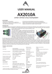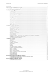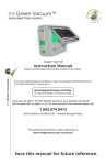
1
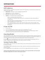
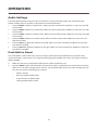
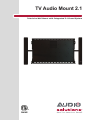
TV Audio Mount 2.1
Television Wall Mount with Integrated 2.1 Sound System
TABLE OF CONTENTS
Safety Instructions ........................................................................................................................ 4
Getting Started............................................................................................................................... 6
Installation...................................................................................................................................... 8
Inputs and Controls..................................................................................................................... 20
TV Settings .............................................................................................................................. 20
DVD Players & HDMI Source Device Settings ........................................................................ 20
Remote Control............................................................................................................................ 21
Remote Control LED/Sensor Location .................................................................................... 21
Remote Control Precautions ................................................................................................... 21
Remote Control (Learning) ......................................................................................................... 22
Operation.......................................................................................................................................23
LED Indicators ......................................................................................................................... 23
Power On/Off ........................................................................................................................... 23
Operating Modes ..................................................................................................................... 23
Volume Control/Mute ............................................................................................................... 23
Audio Settings ......................................................................................................................... 24
Push Button Reset .................................................................................................................. 24
Accessories ................................................................................................................................. 25
Maintenance ................................................................................................................................. 27
Cleaning the Housing and Remote Control ............................................................................. 27
Technical Support .................................................................................................................... 27
Troubleshooting .......................................................................................................................... 28
Compliance .................................................................................................................................. 29
Cable Compliance ................................................................................................................... 29
FCC Class B Radio Interference Statement ............................................................................ 29
WEEE Statement .................................................................................................................... 29
North American Safety Standards ........................................................................................... 29
Features and Specifications ....................................................................................................... 30
Limited Warranty ......................................................................................................................... 31
3
SAFETY INSTRUCTIONS
Please read this en re manual carefully before
moun ng the system to avoid bodily injury and/or
any property loss. If you do not understand these
direc ons, or have any doubts about the safety of
the installa on, please call a qualified contractor
or contact the Audio Solu ons customer service
department. Please check carefully to ensure
there are no missing or defec ve parts. Our
customer representa ves can quickly assist
you with installa on ques ons and missing or
defec ve parts. Replacement parts for products
purchased through authorized dealers will be
shipped to you directly. Do not a empt to use any
parts not provided by the manufacturer. Using
other screws could cause injury or property loss.
Never use defec ve parts, as improper installa on
may cause damage or serious injury. Do not
use this product for any purpose not explicitly
specified by Audio Solu ons. Audio Solu ons
can not be liable for damage or injury caused
by incorrect moun ng, incorrect assembly, or
incorrect use.
slots. Blocking the ven la on openings may
cause the system to overheat, which may
result in injury or property loss.
•
Do not install near any heat sources such
as radiators, heat registers, stoves, or
other apparatus (including amplifiers) that
produce heat.
•
Do not defeat the safety purpose of the
polarized or grounding plug. A polarized
plug has two blades with one wider than
the other. A grounding plug has two blades
and a third grounding prong. The wide
blade or the third prong is provided for
your safety. If the provided plug does not fit
into your outlet, consult an electrician for
replacement of the obsolete outlet.
•
Protect the power cord from being walked
on or pinched par cularly at the plugs,
convenience receptacles, and at the point
where they exit from the apparatus.
•
When the system is connected to a power
outlet, the power is always flowing into the
system. To totally disconnect power you
must unplug the power cord.
•
Only use a achments/accessories specified
by the manufacturer.
•
Use only with the cart, stand, tripod,
bracket, or table
specified by the
manufacturer, or sold
with the apparatus.
When a cart or rack
is used, use cau on
when moving the cart/
apparatus combina on
to avoid injury from p-over.
•
Read these instruc ons – All the safety and
opera ng instruc ons should be read before
this product is operated.
•
Keep these instruc ons – The safety and
opera ng instruc ons should be retained for
future reference.
•
Heed all warnings – All warnings on the
appliance and in the opera ng instruc ons
should be adhered to.
•
Follow all instruc ons – All opera ng and
use instruc ons should be followed.
•
Never aƩempt to install the 2.1 Audio
Mount in a hollow wall.
•
Do not use this apparatus near water – The
appliance should not be used near water or
moisture –for example, in a wet basement
or near a swimming pool, and the like.
•
Unplug the apparatus during lightning
storms or when unused for long periods of
me.
•
Clean only with a dry cloth.
•
•
Do not block any ven la on openings.
Slots and openings in the TV Audio Mount
are required for proper ven la on. Please
ensure that these openings are not blocked
and that no items are placed inside the
Please keep the unit in a well-ven lated
environment.
4
SAFETY INSTRUCTIONS
•
WARNING: To reduce the risk of fire or
electric shock, do not expose this apparatus
to rain or moisture. The apparatus shall not
be exposed to dripping or splashing and that
objects filled with liquids, such as vases,
shall not be placed on apparatus.
•
WARNING: The wall socket plug is used as
disconnect device, the disconnect device
shall remain readily operable.
•
•
•
•
•
This lightning flash with arrowhead
symbol within an equilateral triangle
is intended to alert the user to the
presence of non-insulated “dangerous
voltage” within the product’s
enclosure that may be of sufficient
magnitude to cons tute a risk of
electric shock.
•
The exclama on point within an
equilateral triangle is intended to
alert the user to the presence of
important opera ng and maintenance
instruc ons in the literature
accompanying the appliance.
WARNING: To reduce the risk of electric
shock, do not remove cover (or back) as
there are no user-serviceable parts inside.
Refer servicing to qualified personnel.
The apparatus should be connected to
an electrical wall outlet with a protec ve
grounding connec on.
Always replace a fuse with the same value
as the original fuse.
Do not overload your extension cords or
power strips, as this can result in an electric
shock or fire.
5
•
Do not a empt to service or repair your
TV Audio Mount yourself. Opening the
cover will expose you to high voltages and
other hazards. Servicing is required when
the apparatus has been damaged in any
way, such as power supply cord or plug is
damaged, liquid has been spilled or objects
have fallen into the apparatus has been
exposed to rain or moisture, does not
operate normally, or has been dropped.
If repair is required, please contact your
dealer or refer to a qualified service person.
•
Do not install your TV Audio Mount in an
area subject to outside elements, snow,
moisture or high humidity. This device is
designed for indoor use only.
•
If any of the following occurs, please contact
Audio Solu ons.
◦
The system is exposed to rain or other
moisture.
◦
The power cord is frayed.
◦
The system is dropped or is damaged
in any way.
GETTING STARTED
Introduction
Congratula ons on the purchase of your new Audio Solu ons 2.1 TV Audio Mount System. For maximum
benefit, please read the en re manual before beginning installa on and opera on. With proper usage, you
will experience many years of high quality audio sound from your system.
Please register your system at the following address: www.AudioSolu ons.com
Have your serial number and date of purchase available before you a empt to register.
For future reference, write the serial number found on the Audio Solu ons product, as well as the
purchase date, in the spaces provided below.
SN# _____________________________________
Purchase Date _____________________________
IMPORTANT NOTE!
Before you get started, please measure your television to make sure
it is no wider than 51 inches.
Maximum 51 Inches
This model has been designed to work with most 32 inch and most
55 inch Plasma, LCD, and LED TVs up to 51 inches wide with a
maximum weight of 133lbs (60kg).
Opening the Package
The TV Audio Mount System and its accompanying accessories have been carefully packed in a carton
designed to protect it from transporta on damage. A er opening the carton, check that your system is in
good condi on and that all listed contents are included.
Save the carton and packing material for future shipping.
Package Contents
◦
2.1 TV Audio Mount
◦
Power Cord
◦
Remote Control
◦
Two AAA Ba eries
◦
RCA Audio Cable
◦
Cardboard Moun ng Template
◦
Allen Wrench
◦
Moun ng/Assembly Hardware
◦
This User Manual
Mounting Instructions
Please read all enclosed instruc ons and verify hardware contents carefully before moun ng.
6
GETTING STARTED
Wall Plate Mounting Hardware
#
Part Image
1
2
3
#
DescripƟon
Qty
Square Head
Screw
6
Concrete Bolt
6
M8 Washer
6
Part Image
DescripƟon
Qty
L
M6/M8
Washer
4
M
M4 Washer
4
N
M5 Washer
4
O
M6 Washer
4
P
M8 Washer
4
Q
5x5mm Allen
Wrench
1
R
Cardboard
Template
1
TV Bracket Assembly Hardware
DescripƟon
Qty
A
#
Part Image
M4 x 12 Bolt
4
B
M5 x 12 Bolt
4
C
M6 x 12 Bolt
4
D
M8 x 16 Bolt
4
E
M4 x 30 Bolt
4
F
M5 x 30 Bolt
4
G
M6 x 35 Bolt
4
H
M8 x 40 Bolt
4
I
M4/M5
Spacer
4
J
M8/M6
Spacer
4
K
M4/M5
Washer
4
7
INSTALLATION
STEP 1
Read and understand all of the enclosed instruc ons and verify that all parts are present and appear in
good working order before you begin.
STEP 2
Use the supplied Allen wrench to loosen the socket screws (A) on each side of the lower pole (Figure 1).
You can then separate the unit into two parts: the TV bracket connec on (Figure 2) and the system wall
plate (Figure 3).
A
A
Figure 1 - Separate the TV Bracket and Wall Plate
8
INSTALLATION
Figure 2 - TV Bracket Connection
Figure 3 - Sound System Wall Plate
9
INSTALLATION
STEP 3
Remove the two handles (D) (Figure 4). Rotate the pole assembly downward to gain clear access to the top
moun ng holes.
Figure 4 - Remove Handles
10
INSTALLATION
STEP 4
Place the cardboard template on the wall where you want to mount the system. Is using a non-solid wall,,
such as concrete, use a stud finder to locate the studs, if applicable, and pre-drill the moun ng holes. Be
sure to keep the template level.
Figure 5 - Use Mounting Template and Pre-Drill
11
INSTALLATION
STEP 5
A ach the Wall Plate to the wall.
Wood Stud Mounting
The Wall Plate must be mounted, at the top and bo om, to at least 2 wooden studs, spaced a minimum of
16” apart. Using the correct size drill bit, pre-drill a 2.5” deep hole in each marked loca on. A ach the Wall
Plate to the wall using the included square head screws and M8 washers.
Concrete Wall Mounting
Choose a solid wall area (avoid hollow walls or the joint of the bricks) and drill a 2.5” hole using the correct
size drill bit. Insert the plas c sinker into the hole and then a ach the Wall Plate to the wall using the
included concrete bolts (Figure 6).
Figure 6 - Concrete Wall Mounting
12
INSTALLATION
NOTE: Be sure to choose a wall area that is strong enough to support the combined weight of the TV
and Audio Mount. The loca on should be safe from hazards such as water or crushable items. DO NOT
ATTEMPT TO MOUNT THIS UNIT TO A HOLLOW WALL!
Hollow Wall or Decorative Cardboard
NO!
Figure 7 - Hollow Wall WARNING!
WARNING: Use only the supplied screws intended to the current applica on to avoid personal injury or
property damage.
13
INSTALLATION
STEP 6
A ach the TV to the TV Bracket Connec on (Figure 8). First, remove the round tube (B) from the TV
Bracket Connec on. Next, choose the correct screws (the ones that work with your TV) from the supplied
hardware to a ach the two brackets (C) to the back of the TV. Make sure the brackets are posi oned with
the tube hole at the bo om of the TV.
Once the brackets are connected, slide the round tube (B) back into the TV brackets.
Option 1:
Option 2:
Figure 8 - Attach TV to Bracket
NOTE: Please use the corresponding screws & washers for the holes on the TV back. Assembling with
incorrect screws and washers will damage the holes on the back of the TV. Some TVs without a flat back
may require the use of spacer when a aching the brackets. Make sure the two TV brackets are even and
that they’re using the same moun ng holes on the bracket. Uneven assembly will cause the TV screen to
slant.
14
INSTALLATION
NOTE: You will need at least 2 people to finish this moun ng procedure. To avoid possible injury, do not
a empt to mount the TV alone.
YES!
NO!
STEP 7
Screw the upper pole back into place using the handles (D) (Figure 9).
Figure 9 - Replace Top Pole
15
INSTALLATION
STEP 8
Adjust the two side speakers to the correct width (Figure 10).
Near the top on each side of the TV Audio Mount you will see a locking screw that adjusts the width and
angle of the speakers. Take the supplied Allen wrench and loosen both screws un l you can slide the
speaker poles in and out. Slide the poles out un l the pole stops moving, placing the speakers at maximum
width. Con nue to Step 9 and a ach the TV to the wall mount. Once the TV is mounted at the desired
angle, you can slide the speakers in un l they are next to the TV. Adjust the speaker angle at this me and
then ghten the speaker locking screws un l snug (do not over ghten these screws). Over ghtening a
screw may cause the threads to break and the screw to fail.
Figure 10 - Adjust Speaker Width
16
INSTALLATION
STEP 9
Hang the pre-assembled TV unit on the pole and clip the screws (A) into the lower channel of the Wall
Plate and ghten on both sides when the TV brackets are in place (Figure 11).
Figure 11 - Attach TV Mount to Wall Mount
17
INSTALLATION
STEP 10
Connect the audio wires.
Your TV Audio Mount has three ways to input the audio from your TV (see Figure 12).
1.
Line Level Out is located on your TV panel in the Audio Out sec on. It will have two connectors
marked L (Le -White) and R (Right-Red).
2.
3.5mm Head Phone Jack is located on the TV panel in the Audio Out sec on. Only use this connec on
if your TV does not have a Line Level or Op cal connec on. When using this connec on you must set
the volume of your TV to a level that will allow your Audio Mount to detect audio. This is explained in
more detail in the “TV Se ngs” sec on.
3.
Op cal output is located on your TV panel in the Audio Out sec on. Look for a square connector
marked Op cal or S/PDIF. The audio inputs for the TV Audio Mount are shown in Figure 12.
R
Line In
L
Optical In
Reset
Figure 12 - Audio Input Options
A er loca ng these connectors, decide which you will be using and connect the appropriate cable from
your TV Audio Out to the connector on the TV Audio Mount.
Before you turn your TV on for the first me, lower the TV volume to zero or use the TV menu to turn
your TV speakers OFF. You will now control the volume of your system with the TV Audio Mount remote
supplied with your system. If you have a Learning remote, you can program it to replace the TV Audio
Mount remote.
18
INSTALLATION
STEP 11
Adjust the angle of the TV and then ghten the handles (D) and locking screws (A) (Figure 13). You can then
adjust the width and angle of the speakers and lock the speaker screws as described in Step 8.
NOTE: Arrange your cables to avoid the lt adjustment area. When arranging the wires, please leave
sufficient slack for future angle adjustments.
Max 600mm
D
mm
00
6
ax
M
Figure 13 - Adjust Angle
19
INPUTS AND CONTROLS
TV Settings
For your TV Audio Mount to work properly, you must adjust your TV se ngs for op mal output to the
Audio Mount.
1.
Make sure your TV Balance control is set to center.
2.
If you are using a head phone jack to connect your TV to the Audio Mount, adjust the television
volume to a middle level.
NOTE: It is important that you do not turn the volume up too high, as this will cause the audio to
distort.
A minimum audio se ng is required because the Audio Mount must detect an audio signal to remain
on. If no Audio Signal is detected for 5 minutes, the Audio Mount will power down.
3.
Some TVs have the ability to set the Audio Out on the LINE OUT and/or OPTICAL OUT to Fixed or
Adjustable. If your TV has this feature, use the following remote controller:
◦
Fixed – Use the remote controller that came with the Audio Mount to control the volume.
◦
Adjustable – Use the TV remote controller to control the volume.
DVD Players & HDMI Source Device Settings
Your DVD players and HDMI sources are capable of outpu ng to either BitStream or Linear PCM. It is
very important that you set your device to output in the Linear PCM format to receive audio through the
TV Audio Mount. Otherwise, you will hear buzzing and clicking sounds. This se ng adjustment is only
required when using the Op cal connec on from your TV to the Audio Mount.
20
REMOTE CONTROL
Turn the TV Audio Mount System ON/OFF
LINE
Select the source to Line In
OPT
Select the audio source to Op cal
Select hearing impaired or standard mode
MUTE
Mute the audio
BASS-
Decrease the Bass
BASS+
Increase the Bass
TREB-
Decrease the Treble
TREB+
Increase the Treble
BAL-L
Move the Balance to the le
BAL-R
Move the Balance to the right
VOL+
Increase Volume
VOL-
Decrease Volume
Remote Control LED/Sensor Location
The remote sensor that controls the TV Audio Mount system is located at the bo om of the right speaker.
When a emp ng to use the remote control with the system, be sure to point it toward the remote sensor.
Do not place any obstacles between the remote control and the remote sensor on the speaker. The
effec ve range of the remote control is approximately 30 feet from the front of the speaker.
Remote Control Precautions
•
The remote control should be kept dry and away from heat sources. Avoid high humidity.
•
If the TV Audio Mount System responds erra cally to the remote control or does not respond at all,
please check the ba eries. If the ba eries are low or exhausted, replace with 2 fresh ba eries.
•
Do not take the ba eries apart or expose to heat. Never dispose of ba eries in a fire.
•
Do not subject the remote to undue physical stress, such as dropping or striking it.
•
Do not clean the remote with a vola le solvent. Wipe it clean with a damp cloth.
21
REMOTE CONTROL (LEARNING)
Programming a Learning Remote
If you have a universal (learning) remote, it should be capable of learning the TV Audio Mount remote
control codes. Follow the instruc ons included with the learning remote to incorporate the TV Audio
Mount func ons.
22
OPERATION
LED Indicators
The LED indicator is located on the right side speaker in the logo plate. It is used to help you monitor and
control your audio system.
•
NO LED ON – The system is either unplugged or powered off.
•
Green LED – The system is powered on.
•
Blue LED – Hearing impaired mode is ac ve.
•
Red LED – The red LED indicates mul ple func ons:
◦
Audio is muted from the remote control.
◦
The system is in auto power down mode. This is caused when no audio is detected for an
extended me.
◦
When the system has reached maximum volume, the LED will turn red each me you press the
volume up bu on on the remote control.
◦
When adjus ng the Bass, Treble or BAL controls, the blue or green LED will change to red
momentarily to indicate that the center point or end point have been reached for the control
being used.
Power On/Off
1.
Turn on your TV.
2.
Turn on the Audio Mount using the remote control supplied with the unit.
3.
Select the Audio input source on the Audio Mount Remote (LINE or OPT, depending on which
connec on you chose to connect from the TV to the Audio Mount).
Operating Modes
Your Audio Mount has two modes of opera on: Normal and Hearing Impaired. When in Normal mode, the
LED illuminates green and the system is set to Normal frequency response. In Hearing Impaired mode, the
LED illuminates blue the audio is enhanced to improve the clarity of voice frequencies.
Press the
bu on on the Audio Mount remote control to select the preferred opera ng mode. This
bu on is a toggle and will change between the modes each me it’s pressed.
Volume Control/Mute
Press the VOL + bu on to increase the volume. When you have reached maximum volume level, the limit
the LED will turn RED.
Press the VOL – bu on to decrease the volume. When you have reached the minimum volume level, the
LED will turn RED.
Press the MUTE bu on on the Audio Mount remote control to toggle between audio on and mute.
NOTE: The Audio Mount Remote Control does not func on in a press and hold mode. You must depress
the bu on mul ple mes to increase or decrease the Volume.
23
OPERATION
Audio Settings
The Audio Mount Remote Control does not func on in a press and hold mode. You must depress the
bu on mul ple mes to increase or decrease the controlled func on.
•
•
•
•
•
•
Press the BASS – bu on to reduce Bass,. When you have reached the midpoint or max limit, the LED
will turn RED.
Press the BASS + bu on to increase Bass. When you have reached the midpoint or max limit, the LED
will turn RED.
Press the TREB – bu on to reduce Treble. When you have reached the midpoint or max limit, the LED
will turn RED.
Press the TREB + bu on to increase Treble. When you have reached the midpoint or max limit, the
LED will turn RED.
Press the BAL-L to adjust the balance to the le . When you have reached the midpoint or max limit,
the LED will turn RED.
Press the BAL-R to adjust the balance to the right. When you have reached the midpoint or max limit,
the LED will turn RED.
Push Button Reset
The reset bu on is only used in the event of a major system failure and should not be required under
normal opera on. If the system is no longer func oning properly, RESET will restore the system to factory
default se ngs.
1.
Make sure the Unit is powered on and the Green, Blue or Red LED is on.
2.
Push the RESET bu on and hold down un l the Green, Blue, or Red LED turns off and then the Green
LED turns on. If audio is being sent to the unit, you should be able to hear the audio through the unit.
The unit will reset the following user controls:
◦
Master Volume
◦
Bass and Treble to Mid points
◦
Input Selector to Op cal Input
◦
Hearing Impaired turned off
24
ACCESSORIES
Model Number
Description
TVAMDVDSHELF
Add-on DVD Shelf for Audio
Mount
TVAMPEDESTAL
Pedestal Mount
FMWM3260-TVAM
Full Mo on Wall Mount
Product Image
25
ACCESSORIES
Model Number
Description
CM3260-TVAM
Ceiling Mount
FTVS3260-TVAM
Rolling Floor Stand
Product Image
26
MAINTENANCE
Cleaning the Housing and Remote Control
•
Do not use vola le solvents such as toluene, rosin or alcohol to clean the TV Audio Mount. These
chemicals may damage the system.
•
Use a so clean cloth for cleaning.
•
You can use a moistened so cloth with diluted neutral cleaner if your remote or system becomes
seriously contaminated. Make sure that you wring water out of the cloth before cleaning to prevent
water from penetra ng into the housing. Wipe the housing with a dry clean cloth.
Technical Support
Products are o en returned due to an opera on problem rather that a defec ve product that may result in
unnecessary shipping charges billed to you. Our trained support personnel can o en resolve the problem
over the phone. For more informa on on warranty service and/or repair, a er the warranty period, please
contact our Support Department.
Customer support and quality service are a very important part of Audio Solu ons commitment to service
excellence.
For technical assistance, contact Audio Solu ons Technical Support Department by email or phone.
Please have your TV Audio Mount model number, serial number, and date of purchase available before you
call.
Email: techsupport@audiosolu ons.com
27
TROUBLESHOOTING
If the TV Audio Mount System fails to operate, check the opera on in accordance with the following.
Problem
Solution
No power
Check to verify that the AC Cord is securely connected to the AC socket.
Press the
No sound
Buzzing, humming,
clicking or other
unusual sounds
bu on on the remote control.
1.
Make sure you have not muted the system by pressing the MUTE bu on
on the remote control.
2.
Press the Volume + bu on a few mes to ensure the volume is not at
the lowest level.
3.
Verify that your TV is powered on.
4.
Press the LINE or OPT bu on on the remote control to select your
source (depending on how you connected your TV to the Audio Mount).
1.
If you are using Line In to connect from the TV to the Audio Mount,
make sure that both ends of the audio cable are connected securely at
the TV and the Audio Mount.
2.
If you are using Op cal In to connect from the TV to the Audio Mount,
make sure that your DVD player and/or HDMI device is set to output
audio in Liner PCM Format. If this does not correct the problem, try
using the Line In to connect to the Audio Mount.
3.
Set the “SAP” se ngs on your TV to “Stereo” or “Mono”.
Audio sounds distorted
If you are using the Line In for the Audio Mount, check to verify that the
volume for the source device is not set high. If you hear audio distor on,
lower the volume of the source device un l you hear normal audio.
System does not
respond to the remote
control
1.
Check the ba eries in the remote control and replace if necessary.
2.
Press the RESET bu on on Audio Mount.
28
COMPLIANCE
Cable Compliance
Cau on: Always use a power cable that is properly grounded. Please use the AC Cords listed below for each
area:
USA
Canada
Germany
UK
Japan
UL
CSA
VDE
BASE/BS
Electric Appliance Control Act
FCC Class B Radio Interference Statement
This equipment has been tested and found to comply with the requirements listed in FCC Regula ons,
Part 15 for Class “B” digital devices. Compliance with these requirements provides a reasonable level of
assurance that your use of this product in a residen al environment will not result in harmful interference
with other electronic devices. This equipment generates/uses radio frequencies and, if not installed and
used according to the instruc ons found in the user’s manual, may cause interference harmful to the
opera on of other electronic devices.
Compliance with FCC regula ons does not guarantee that interference will not occur in all installa ons. IF
this products is found to be the source of interference, which can be determined by turning the unit “OFF”
and “ON” please try to eliminate the problem by using one of the following measures:
•
Relocate the device that is being affected by the interference.
•
U lize power outlets that are on different branch (circuit breaker or fuse) circuits or install AC line
filter/s.
This Class B digital apparatus complies with Canadian ICES-003.
WEEE Statement
(Waste, Electrical and Electronic Equipment)
The WEEE direc ve places an obliga on on all EU-based manufacturers and
importers to take-back electronic products at the end of their useful life.
Metra accepts its responsibility to finance the cost of treatment and recovery
of redundant WEEE in accordance with the specific WEEE recycling requirements.
This symbol on the right indicates that this product must NOT be disposed of
with other waste. Instead, it is the user’s responsibility to dispose of their waste
electrical and electronic equipment by handing it over to an approved
reprocessor, or by returning it to Metra for reprocessing.
North American Safety Standards
Metra Electronics Corpora on is proud to announce that the 2.1 Audio Mount is fully
ETL Listed. The ETL Listed Mark is proof of product compliance to North American
safety standards. The mark also indicates that the manufacturer’s produc on site
conforms to a range of compliance measures and is subject to periodic follow-up
inspec ons to verify con nued conformance. Metra is working to make your safety
and sa sfac on our priority.
29
FEATURES AND SPECIFICATIONS
Features
•
Klippel laser-op mized 6.5” woofer for high linear excursion and powerful bass
•
24 bit/48 kHz Digital EQ and Crossovers for high quality audio
•
True silk dome tweeter for clear, crisp high frequency response
•
Slot-loaded Sub Woofer in an op mally vented enclosure delivers high efficiency and low distor on
•
Midrange-tweeter-midrange (MTM) design projects even frequency response throughout the room
Specifications
•
Frequency Response: 40Hz - 25kHz
•
Subwoofer: 6.5” long throw cone
•
Midranges: Dual 2.5” treated cellulose cone (per speaker)
•
Tweeter: 19mm (3/4”) ferro-magne c fluid damped pure silk dome (per speaker)
•
Pole Lengths:
Fully Closed
Fully Open
30
LIMITED WARRANTY
Audio SoluƟons – Audio Mount – Limited Warranty – Valid in the United States and Canada
This 12 month limited warranty is provided by Metra Electronics Corpora on for the Metra product iden fied by the
purchaser’s registra on as indicated below, and there are no other warran es, expressed or implied, except as required
by law, including warran es of merchantability and fitness for a specific purpose, that are provided for herein, however all
such implied warran es, if any, are limited to the dura on of this specific limited product warranty. Some states do not
allow limita ons on how long an implied warranty lasts, so the above limita ons may not apply to you.
Metra Electronics Corpora on shall not be liable, under any circumstances, for incidental, indirect, special, and
consequen al or mul ple damages as a result of the sale or use of this product. Some states/countries do not allow the
exclusion or limita on of incidental or consequen al damages, so the above limita on or exclusion may not apply to you.
It is recommended that the purchaser execute the product registra on and warranty registra on via the web within ten
days of purchase.
Limited Product Warranty:
This is a 12 month limited warranty, subject to the condi ons, limita ons and exclusions iden fied herein. Metra
Electronics Corpora on warrants to the original purchaser of the registered or iden fied product for a period of one year
from the date of purchase, that the product shall be free of defects in design, material and workmanship, and subject to
the limita ons set forth below; Metra Electronics Corpora on will repair or replace, at its op on, any defec ve unit. Metra
hereby warrants to the original retail purchaser of this product that should this product or any part thereof, under normal
use and condi ons, prove to be defec ve in material or workmanship within one (1) year from date of original purchase,
such defect(s) will be repaired or replaced with recondi oned product (Metra’s op on) without charge for parts and repair
labor. Purchaser must return the product to Metra, return receipt requested or by other means that confirms delivery and
Metra shall make the said repairs or replacement within 60 days of receipt. In some instances the product may have been
discon nued and cannot be replaced, or repaired. In that instance Metra shall in its discre on a empt to replace the
product with a substan ally similar product in model or design or pay the purchaser a sum for the then fair market value
of the price, considering the amount of me since sale, and the use of the product. This Limited Warranty is the original
retail purchaser’s sole remedy for any and all such defect(s).
CondiƟons and LimitaƟons:
Proof of purchase is required (i.e. the sales receipt of other proof of payment)
Damage caused by accidents, abuse, misuse or modifica on of the product will render this warranty null and void.
This warranty is applicable only to the original purchaser and is not assignable or transferable.
To obtain repairs or replacement under the terms of this warranty, please contact Metra at 1-800-221-0932 or visit
www.metra-online.com. You will need to provide proof of purchase (dated receipt showing store where purchased) and
product serial number in order to receive warranty service. The purchaser is required to send the product back to Metra
Electronics Corp or to a designated repair center and the purchaser is responsible for all charges for shipping and handling.
This Limited Warranty does NOT cover:
Products which have been subject to abuse, accident, altera on, modifica on, tampering, negligence, misuse, improper
installa on, lack of reasonable care, unauthorized repair or service, or if the model or serial number has been altered,
tampered with, defaced or removed.
Ini al installa on or the removal and re-installa on of product.
1.
Cosme c damage, damage that occurs in shipment, act of God or natural disaster.
2.
Missing accessories or components.
3.
Products used for any and all commercial purposes.
THE EXTENT OF METRA’S LIABILITY UNDER THIS WARRANTY IS LIMITED TO THE REPAIR OR REPLACEMENT AS PROVIDED
ABOVE AND, IN NO EVENT SHALL METRA LIABILITY EXCEED THE PURCHASE PRICE PAID BY THE ORIGINAL RETAIL
PURCHASER FOR THE PRODUCT.
Any ques ons of No fica ons regarding this warranty should be addressed to:
Warranty Department, Metra Electronics Corpora on
460 Walker Street, Holly Hill, Florida 32117.
THIS WARRANTY IS IN LIEU OF ALL OTHER EXPRESS WARRANTIES OR LIABILITIES. ANY IMPLIED WARRANTIES, INCLUDING
ANY IMPLIED WARRANTY OF MERCHANTABILITY, SHALL BE LIMITED TO THE DURATION OF THIS WRITTEN WARRANTY. IN
NO EVENT SHALL METRA BE LIABLE FOR ANY CONSEQUENTIAL OR INCIDENTAL DAMAGES FOR BREACH OF THIS OR ANY
OTHER WARRANTY EXPRESS OR IMPLIED WHATSOEVER.
No person or representa ve is authorized to assume for Metra any liability other than expressed herein in connec on with
the sale of this product. Some jurisdic ons do not allow limita ons on how long an implied warranty lasts or the exclusion
or limita on of incidental or consequen al damages so the above limita ons or exclusions may not apply to you. This
warranty gives you specific legal rights and you may also have other rights, which vary from jurisdic on to jurisdic on.
31
©2011 Metra Electronics Corpora on, 460 Walker Street, Holly Hill, FL 32117-2699
Specifica ons are subject to change without no ce.
All trademarks are the property of their respec ve owners.
www.audiosolu ons.com