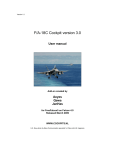
1
FSUIPC – QUICK START TUTORIAL
“ Controlling A Brand New Decade of Flight Simulation Hardware ! ”
Courtesy of : www.SimSamurai.net
V1.1 January 15, 2010
Credit to Pete Dowson for creating FSUIPC … The “Holy Grail” for the world of Flight Simulation !
NOTE : This tutorial is primarily designed for the assignment and calibration of CH Products USB controller
device hardware using the FSUIPC registered payware utility. However, this could also serve as a general
guide for use with any USB device such as Saitek, Precision Flight Controls, or many others.
NOTE : Compatibility for this tutorial has been tested for Windows XP 32/64, Windows Vista 32/64 and
Windows 7 32/64 using Flight Simulator 2004 (FS9) and Flight Simulator X (FSX).
NOTE : Use of this tutorial requires the purchase of the FSUIPC utility payware version 4.57 (FSX) or
version 3.96 (FS9) which is downloaded from www.Schiratti.com and paid for at www.SimMarket.com
NOTE : This quick start guide for the FSUIPC registered edition will detail how all of your USB device controllers can
be exclusively assigned and or calibrated by FSUIPC and not FS itself, nor by the CH Control Manager software that
is routinely associated with CH Product devices. Furthermore this guide contains options of how to only have your
CH Throttle Quadrant controlled by FSUIPC while your Yoke and Rudder pedals can remain controlled by the Flight
Simulator or you can configure these in any combination therein. Thus this tutorial will detail elements of key flexibility
for your configuring desires. Finally the last pages of this guide detail how to create specific aircraft type user profiles
so that you can easily fly a multitude of various aircraft without having to continually reassign control functions to match
each aircraft type. If creating user profiles is of interest to you please see the last pages of this guide before you begin
programming your devices. You may also want to consult pages 26 and 27 of Pete Dowson’s own default User Guide.
Once FSUIPC is installed its config file is located inside the Modules folder found in the root directory of your simulator.
A FEW BRIEF WORDS OF P.C. ADVICE
If you like to fly online I also highly recommend finding my “Mega-Ultimate FS-Inn Installation Tutorial for VATSIM”.
This separate tutorial is included in the sim-tech “UGTAFS” manual available from www.simsamurai.net but can also
be found on the AVSIM forums or elsewhere. This other 13 page tutorial I mention is a very detailed account of how to
properly set up everything you will ever need to know for flying in VATSIM while using FS-Inn as a connection host.
More importantly this other tutorial also includes several “pre-configuring” pages that can come in very handy before
you proceed with this FSUIPC tutorial. In many ways both of these two tutorials can and will go hand in hand. The
FS-Inn set-up tutorial has some key information about how to properly set-up your PC before you install FSUIPC or
FS-Inn as a connection utility. There is a lot of additional information provided on the other tutorial that will also help
you to optimize your computer for flight simulation use with Windows XP, Vista, and Windows 7. So please grab it,
read it, and then proceed on with this tutorial if you have purchased the payware version of FSUIPC.
Now onward and upward with the meat, potatoes, and gravy that is… FSUIPC !
GETTING STARTED WITH THE FSUIPC CONTROLLER UTILITY
#1 – If you haven’t already, purchase your respective version of FSUIPC from www.SimMarket.com. You
can find the version details specific for your sim version at www.Schiratti.com. Currently these are versions
V4.57 for FSX and V3.96 for FS9. (as of January 2010)
#2 – Once a file version is purchased (current cost average is $30.00 U.S.) extract the FSUIPC Zip File to
its own folder and access the FSUIPC .exe auto installer.
#3 – Run the auto-installer .exe. file. It will auto-locate your sim installation and will deposit many files into
the simulator’s Modules Folder. If required, make sure you direct it to where your sim is located.
#4 – During final installation you will want to now register the FSUIPC controller utility via the installer.
The registration key is initially emailed to you and can be accessed via your personal Sim Market account.
NOTE : Once installed move the FSUIPC zip file to a safe location such as your dedicated storage drive!
#5 – After a successful installation of FSUIPC start up the Flight Simulator and load up the default flight with
a default aircraft such as the Beechcraft King Air 350.
#6 – Hit Alt+Enter to access the main FS Toolbar Menu located at the top of your simulator window screen.
Scroll over to Modules and then select FSUIPC from the dropdown. This will now open the FSUIPC
payware device controller assignment and calibration utility.
#7 – You can initially press the “Set To Default” button if desired. Doing so will only clear out any and all
previous data stored in the Weather Options tab and the Miscellaneous Options tab. This should only be
necessary if you have upgraded your FSUIPC payware from a previous installed version.
CONFIGURING THE MICELLANEOUS OPTIONS TAB :
Steps #8 - #19 are some initial settings that I have personally found to be the most common for all users.
If you do not plan to configure all your devices at this time you may just consider setting these up first.
There are more settings than this and they can all be better explained in the default Dowson User Manuals.
Step #9 below is particularly useful if you want to assign your trim function to an axis lever as this alleviates
a known bug in the sim while the autopilot is engaged if the trim is assigned to an axis. (Thanks Pete !!!)
#8 –
Under the "Fixes and Improvements" section now enable the following parameters;
#9 –
Enable “Discon elev trim axis for AP” ** ( Use if you have aircraft trim assigned to an axis lever ! )
#10 – Enable “V/S sign correction” - see pg. 19 of FSUIPC user manual if you notice AP V/S issues!
Under the "FS2002/2004" section enable the following;
#11 – Enable “Fix Control Acceleration” (only if you use joystick/yoke controllers...and we do here.)
#12 – Enable “Make NAV freq increment = 50 KHz”
#13 – Enable “Clear Weather Stops Dynamics”
Under the "Additional Facilities" section enable these four options;
#14 – Enable “Extend Battery Life” - and set numerical factor to 20 (which equals 30 minutes battery life)
#15 – Enable “Smooth IAS for external programs”
#16 – Enable “Keep FS clock sync'd to real time” (fixes default FS time lag bug)
#17 – Enable “Throttle Sync to Sync Thr/Prop/Mix” (enables the Throttle Sync hot key assignment
synchronize all Throttle, Prop Pitch and Mixture settings to the current Engine 1 value)
2
CONFIGURE THE HOT KEY ASSIGNMENTS TAB :
#18 –
Multiple Throttle Synchronization
- Set To : Shift + M (toggle for on /off)
#19 –
Resume All Engine Control
- Set To : Shift + N (for "Normal Ops")
CH PRODUCTS DEVICE ASSIGNMENTS AND CALIBRATIONS WITH FSUIPC :
The remainder of this tutorial is specifically tailored for the suite of three CH Products USB flight controller
devices. These are; CH Control Yoke, Ch Pro Pedals, and the CH Throttle Quadrant.
The assignment and calibration methods in this guide allows the registered version of FSUIPC to handle
and control either some or all of the assignments and or calibrations of all your control devices axes,
joystick buttons, and momentary type toggle switches. The FSUIPC utility can also control these same
functions on any other USB type of gaming control device as well any properly constructed home-made
control devices. Depending on your own needs you can fully allow for FSUIPC to control and calibrate all of
these devices or you can decide what combination you desire to allow sharing of input control between the
default (or customizable) simulator assignment functions and your new customizations within FSUIPC.
While FSUIPC is often recommend for allowing total control of all devices this is not fully necessary for most
common users with only a few pieces of hardware. However, in all regards of a device assignment utility,
be it the in house system provided by the sim software itself, or the FSUIPC utility, you must choose one
method of assignment for each individual axis and one method for each individual joystick button. Thus
know that both utilities must not perform simultaneous control nor calibrate the same axis or button at the
same time. Therefore, as is explained in the next section, you must either first delete some assignments in
the sim’s control assignment axes and joystick tabs before you use FSUIPC, or, you can option to disable
the simulator’s joystick function altogether which if doing so would then allow all axes and buttons to be
entirely controlled by FSUIPC. Therefore one method should be chosen before proceeding any further.
STEP 1 – DISABLING THE DEFAULT FS JOYSTICK CONTROL FUNCTIONS
NOTE : -- After having used FSUIPC to control all functions of my Throttle, Yoke, and Rudder Pedals I was
quite satisfied with all the results save for the POV (8-way Point Of View / "hat" switch) assignments which
are detailed several sections ahead. Once I assigned the POV using FSUIPC I found that the results were
not as satisfactory to my liking compared to the default POV function built into FS9 or FSX. Therefore you
may want to option to keep the FS joystick function enabled if you want to still allow the default FS mapping
functions to control both your Yoke and Rudder pedals. (You can however calibrate them with FSUIPC)
I however do highly recommend using FSUIPC for complete control of your CH throttle quadrant as it does
provide a much more realistic result apart from the default FS functions or by those of the CH Products
Control Manager software (CHCM). Therefore, if you want to follow this recommendation then keep the FS
joystick function disabled. If you wish to keep the joystick function enabled and had deleted out any default
assignments in the sim up to now you can always reset them with the "restore to default" options for the
Yoke, Rudder, and Throttle. However, for the throttle you would make sure that you do specifically delete
out all the stock throttle functions in the sim to include its axes and joystick functions found in the flight sim’s
joystick assignment tabs. Thus specifically delete the Flight Sim’s built in joystick assignments for the
throttle quadrant’s axes and button assignments. Do not delete the keyboard throttle assignments. These
two steps are quite necessary because again, as recommended, you will specifically use FSUIPC to assign,
control, and calibrate the CH Throttle Quadrant as shown beginning in Step 2 / #25. If you do want FSUIPC
to fully control all of your devices then follow along with steps #20 - #23.
#20 – Start the Simulator, Get into the default flight, and access the FS toolbar menu. Then scroll to
Options \ Controls \ Assignments.
#21 – To entirely disable all Joystick functionality go to Options \ Controls \ Disable Joystick. Once
disabled, all your CH product devices are now “dead” in FS. If doing so you must now use the FSUIPC
utility to fully control (i.e. assign and calibrate) all axes and buttons on all your control devices.
#22 – Again, if you desire to only delete the Axes assignments for a device you can option to leave the
Joystick function enabled but must then manually hand delete out all Axes and or Button assignments for
each device. This goes for all USB devices connected to your PC for use with FS. (if joystick is enabled)
#23 – In all instances of performing any deletes / edits of the Axes or Button assignments for a control
device you should leave all the default Keyboard assignments alone!
#24 – Shown below are the assignment utilities you will use throughout this tutorial. On the left is the default
Controls – Assignments window for Flight Sim 9 while the right shows the FSUIPC assignment utility.
In both cases the Axes Assignment tabs are open. Again if you plan to use FSUIPC for axes assignments
then either disable your joystick function in FS or simply delete all Axes functions in FS for each device you
plan to allow FSUIPC to control. Obviously the second method, while more work, allows the most flexibility.
Å OR ? Æ
STEP 2 – REASSIGNMENT OF THROTTLE QUADRANT AXES WITH FSUIPC
NOTE : FSUIPC is fully recommended for handling all the functions of your CH Throttle Quadrant and is
especially well suited for control of its 6 lever axes. In this tutorial you will have no need for any installation
nor any configuring of the CH Control Manager software (CHCM) provided by CH Products. I do not use
this software for my throttle assignments and calibration and the CH throttle works flawlessly using FSUIPC
as its solitary control manager. If you have read that the CHCM is necessary in other forums, other threads,
or other tutorials, please disregard that information. If necessary re-read Step 1 and #20 - #24 so as to
decide whether you will use the “joystick disable” method or will delete all the default axes assignments in
the simulator so as to allow FSUIPC to take over the axes and perhaps joystick button control of this device.
#25 – While sitting in your default King Air aircraft, access the FS Toolbar menu via Alt or Alt+Enter and
then select the Modules dropdown, and select FSUIPC to access the FSUIPC assignment utility.
#26 – Now access the Axis Assignment tab located on the FSUIPC utility.
#27 – We will now start out with mapping out the CH Throttle Quadrant first. If you do not own one you
can move onto mapping out any other devices that you wish for FSUIPC to control. Remember that this
also depends on whether you used the enable/disable joystick options or whether you deleted some axis
and or button assignments in FS so as to allow FSUIPC to now control these Axes or Buttons.
NOTE : The Joy # box found on the Axis Assignment tab shows the currently selected device. This could be
Joy #0, or Joy #1, or Joy #2, etc.. (Joy #0 is actually a device) It reads whatever device you are actuating at
the moment. This value will change as you move axes on any of your USB controllers. Thus the Joy # will
either be #0 #1, or #2 as we are currently using 3 USB devices in this example all three of which do have
axes available for assignment. (and also buttons whose assignments are explained later.)
4
#28 – To begin, move the far left lever axis on the Throttle Quadrant from full aft to full forward and while
doing so press and hold the Rescan button on the Axis Assignment tab.
#29 – Now release the Rescan. If the lever was properly recognized you should see ascending/descending
numerical values that change under the Raw In / Raw Out display next to “Delta”. For example my lever
data values say In 16383 and Out 16383. Yours may vary slightly and if so this is normal.
#30 – Now that FSUIPC has recognized our first axis lever you will now select the “Send Direct to FSUIPC
Calibration” found just under the “Type of Action Required” option section. This allows you to choose
how and where the new axis assignment is sent.
#31 – Below this section now select the available checkbox (check it) and then from the first dropdown
menu now select “throttle 1” from the many available FS controls list.
#32 – You now have five remaining throttle axis levers to assign and will repeat the process in the exact
same way. Therefore, repeat steps #28 - #31 using Rescan \ Send Direct To and Control Assignment.
NOTE : Follow along with the assignment table below. Once complete you should have the following new
assignments mapped out in FSUIPC suitable for use with any twin-engine aircraft such as a twin-engine
piston prop or twin-engine turbo prop. After having completed the 6 lever assignments using #28 - #32
they should match up with the configuration in the list below. However, please note that you will not see a
list such as this in the FSUIPC controller “Axes Assignments” tab. This list simply illustrates what has
been accomplished up to this point while assigning the six levers on our throttle quadrant.
Joy#2
Joy#2
Joy#2
Joy#2
Joy#2
Joy#2
ThQ Lever 1
ThQ Lever 2
ThQ Lever 3
ThQ Lever 4
ThQ Lever 5
ThQ Lever 6
Throttle 1
Throttle 2
Propeller 1
Propeller 2
Mixture 1 **
Mixture 2 **
NOTE: In this example at left it says Joy#2. This is just an example
of how FSUIPC read my own USB throttle device. Depending on the
order in which you plugged your devices in and on which USB port
will determine what Joy# FSUIPC assigns to your device. So if this
Joy# is reading something different for you do not worry about it.
** Turbo props have "Condition Levers" rather than the "Mixture Levers" of piston prop aircraft.
However do know that the FS assignment is actually Mixture for both engine types.
AXES CALIBRATIONS
NOTE : Steps #33 - #44 detail how to properly calibrate any type of lever axis. The goal for throttle axes
calibrations is to establish a clear and consistent idle range across all six levers to include the two throttle
levers, the two prop levers, and the two mixture levers. Mr Dowson also recommends moving each lever a
little away from the extremes before clicking the “Set” function to ensure there's a small "dead end" at each
far end of the lever so that should the values arriving from the device vary a little, you are always assured of
reaching the extreme -- e.g. full thrust and full idle. The latter is VERY important if you want to engage
reverse via a reverser axis as they will not operate unless the throttle is truly at idle. Lastly, I use FSUIPC
exclusively without aid of the CH Products Control Manager (CHCM) and my throttle works perfectly.
#33 – You will now move onto the Joystick Calibration tab. Once there you will calibrate 2 levers per
pages 3,4, and 5 which are all accessed from within this one calibration tab via two small left /right arrows
Å Æ at the top of this tab which will cycle through these pages located within the joystick calibration tab.
#34 – Now that all 6 levers have been assigned you will now need to calibrate them one at a time based on
their functions. Using lever 1 / throttle 1 as our example you will then similarly apply the next steps to the
other five levers on the throttle quadrant once the first lever calibration is complete.
#35 – While now on the Joystick Calibration tab, click on the Reset button. This will simply clear out any
previous or wrong data values for the lever if they even exist.
#36 – Using the black Left and Right arrows as mentioned earlier now press the right arrow to scroll over to
page "3 of 11” which says “Separate Throttles Per Engine".
#37 – On Page 3 of this tab you will see that there is a Set button and a corresponding value field for
Reverse Idle, and Max. Note that the idle position actually has two fields beneath its own Set button.
This is important as will be explained momentarily as this dual setting is used for calibrating the idle detent
positions on our throttle.
#38 – The In / Out value field beneath each Set button displays the value of triggered movement for each
axis that was assigned earlier. If you now move throttle levers 1 & 2 independently you should again see
that these In / Out values are ascending and descending from a large positive value to a negative value.
#39 – To set the Reverse Thrust position of the first of the two throttle levers press the main Set button
under the throttle 1 dialog box.
#40 – Now pull the first far left lever (throttle 1) all the way rearward (aft) and then press the Set button right
under the Reverse column.
#41 – To now set the Maximum thrust value, push the same lever fully forward and now press the Set
button under the Max column. This now sets your maximum thrust value for throttle lever 1.
#42 – To set the Idle Range Values correctly you now have to determine and create what will be sufficient
upper and lower idle value ranges which should actually be done when each side of the lever rests on the
mid point of the frictional detents located just to either side of the idle detent resting position. Thus when
properly set the lever, when pushed forward out of the detent, engages thrust and like wise when pulled
rearward out of the detent, the lever will engage reverse thrust.
#43 – To set these two values first position the lever in the resting idle detent position and then push the
lever forward just slightly enough so that it rests in the friction notch or “hump” but not so far forward so that
it falls out of the friction point and out of the detent into the first “low thrust” position. While keeping it there
on the friction hump now press Set under the Idle column. This sets the top idle detent value.
#44 – To now set the lower idle detent value pull the lever rearward and using the same technique position
the lever or the mid-point of the lower frictional hump. Again, do so while you feel the lever engaged in the
friction area but not slipped into the full aft position and press the Set button gain under the Idle column.
This now sets the lower value for the idle detent potion.
As an example this gave me a top idle value of neg -13446 and a lower value of -12429
NOTE : Be aware that there can obviously be a little free play or looseness in the detent position and if the
upper and lower idle ranges were to be set too loose or rather too small or narrow then you will find that the
aircraft can be either throttled or reversed too easily or perhaps feathered too easily, or the fuel mixture cut
off too easily. Try to understand that the full aft reverse value, for example, is defined as everything from the
lowest part of the levers rearmost position up to the start of where we define the entry of the detent position.
Therefore if these values are not set to the proper tolerances which I just explained in steps #42 - #44 you
may inadvertently trigger functions you are not wanting to trigger such as reverse thrust, full feathering, or
mixture cut-off. Therefore there are four values to be aware of :
(A; Full Thrust, B; Start of Idle Detent, C; Rear of Idle Detent, and then lastly D; Full Reverse position.)
Therefore the obvious range between D to C is the REVERSE, C to B is IDLE, and B to A is THRUST.
Because of how the CH Product throttles are physically manufactured, you will actually want to create very
small ranges for the reverse, feathering, and fuel cut off features. This is why the lower idle position is set
between the detent friction point and the bottom most part of the levers slot on the throttle quadrant. While
this unfortunately only leaves an aft triggering range of about 5mm and not a more realistic 2cm., it must be
this way simply due to the physical location and construction of the Ch Throttle levers which are obviously
less than real world standards. Therefore when you set both of the idle detent values for each lever it is
best to press the idle range “Set” command key in FSUIPC while the lever is physically set on the mid point
of the “friction humps” just to either side of the detent slot. Doing so result in a slightly wider idle detent
range and in doing so this causes much less unwanted command triggering while in the idle position.
#45 – You will now repeat steps #37 - #44 to set up the second throttle lever.
THE SLOPE FUNCTION FOR AXES
On most every axes calibration settings you will see a button called ‘Slope’ for each axis. If you press this
button it will open a small box that allows you to set a user definable curve for that specific axis. While the
default setting is of course fine, you can always tailor these to your liking if desired. More of this is explainer
later as I have found the slope function for the brakes to be useful. If you are unsure how to use this then
just leave this setting alone for now as it is not mandatory for calibration. (only for fine tuning it) You can
also consult the Dowson user manuals for more details on the Slope settings.
THROTTLE – MIXTURE CONTROL LEVER AXIS CALIBRATION
#46 – While still on the Joystick Calibration tab move onto the Mixture Controls page which is Page
"4 of 11 Separate Mixture Controls". As before use the left /right Å Æ arrows to select this page.
#47 – We will now set up the two far right levers (5 & 6) on the throttle which we had earlier assigned to
Mixture 1 and Mixture 2 while on the Axis Assignment tab.
#48 – Using similar methods from steps #37 - #44 press the Mixture 1 main Set button and move the
Mixture 1 lever full aft rearward then press Set under the Min column.
#49 – Now move the Mixture 1 lever fully forward and press the Set button under the Max column.
#50 – Now move the Mixture 1 lever into the idle detent, press the lever forward slightly onto the frictional
hump (but not fully out of it) and press Set under the Idle column.
#51 – Now move the Mixture 1 lever to the rear of the idle detent onto the rear frictional hump (but not fully
aft past the friction point) and again press the Set button under the Idle column.
#52 – Now repeat steps #46 - #51 to set up the second fuel mixture lever in the same way as the first.
THROTTLE – PROPELLER RPM / PROP PITCH LEVER AXIS CALIBRATION
#53 – While remaining on the Joystick Calibration tab you can now move onto Page "5 of 11 Separate
Prop Pitch Controls" As before use the main left / right Å Æ arrows to select Page 4 of this tab
#54 – On this 4th tab page we will now set up the two middle levers (3 & 4) for our Prop Pitch 1 and Prop
Pitch 2. Using similar methods from steps #46 - #51 press the main Set button for Prop Pitch 1, move the
lever fully aft rearward and press the Set button under the Feather column.
#55 – Now move Prop lever 1 fully forward, and press the Set button under the Max column.
#56 – Now move Prop lever 1 into the detent, press it forward onto the frictional hump and press the Set
button under the Min column.
#57 – Now move Prop lever 1 to the rear of the detent onto the rear frictional hump and again press the Set
button under the Min column.
#58 – You must now repeat steps #53 - #57 to set up the second Prop Pitch lever.
#59 – FINAL THROTTLE NOTE : You are now done with all six throttle axes assignments and calibrations.
We will assign the 12 momentary toggle switches on the front of the throttle quadrant later. You can move
onto that portion of this guide right now if you have decided to keep your Yoke and Pedals operating under
the normal built in assignment features of the simulator. If you have instead decided that you do in fact
want FSUIPC to fully control all other USB devices such as your Yoke and Rudder pedals then proceed on
with the next two sections which detail how to configure the CH Yoke and CH Pro Rudder pedals with
FSUIPC. If this is the case you may want to consider use of the “disable joystick” command in the flight
simulators Options \ Controls \ Joystick section so as to allow FSUIPC to fully control all these devices
otherwise do not forget that it would be necessary to delete out all of the individual joystick axes and button
assignments in FS. For more on these “master control” decisions review “Step 1” on page 3 of this guide.
STEP 3 – CONFIGURING THE CH YOKE AXES WITH FSUIPC
NOTE : Remember that this section is optional. Please see "Step 1" about disabling joystick functions
before making any changes to your yoke assignments as steps #60 - #69 below may not be needed.
#60 – To begin configuring the CH Yoke return to the Axis Assignment tab of FSUIPC.
#61 – Just like in Step #28 press and hold Rescan while you push and pull your Yoke fully forward and aft.
#62 – Once the axis is recognized press the “Send Direct to FSUIPC Calibration” under “Type of Action
Required”. Check the first box and then select Elevator (for pitch movement) from the dropdown menu.
#63 – Now turn and Roll the Yoke fully side to side left to right and press and hold Rescan.
#64 – Once the axis is recognized press the “Send Direct to FSUIPC Calibration” under “Type of Action
Required”. Check the first box and then select Aileron (for roll movement) from the dropdown menu.
#65 – Now that both the Pitch and Roll movement axes are assigned now click on the Joystick Calibration
tab and select Page”"1 of 11 : Main Flight Controls" using the left /right page change arrows on this tab.
#66 – Press the Ailerons Set button then roll the Yoke fully right to its stop and press Set under the Max
column. Then roll the yoke full left and press Set under the Minimum column.
#67 – Now, center the Yoke, roll in right approximately 1 cm and press Set under the Center column and
then roll the yoke left 1 cm from center and again press Set under the Center column.
#68 – Now press the Elevator Set button. Then push the Yoke fully forward to its stop and press Set under
the Minimum column. Then pull the Yoke fully aft and press the Set button under the Max column.
#69 – Now completely center the Yoke. Push it forward about 1 cm and press Set under the Center
column. Then re-center the Yoke and pull it rearward 1cm and then press Set again under the Center
column. These last two steps create a small dead zone which is explained below.
CREATING A DEAD ZONE ON THE YOKE
In both cases of centering of the roll and pitch in Steps #67 - #69, the 1cm – 2cm square you are creating
is a dead zone for the center positions of these two axes movements. This can be very necessary because
the CH Yoke, while an effective device controller, does not have the best internal components nor has the
best spring tension for returning the device to the exact center position in regards to both the roll and pitch.
Therefore the area created in steps #67 - #69 creates a wider dead zone where both the aircrafts two roll
ailerons and pitch elevator will remain neutral. Thus creating this dead zone effectively helps your aircraft to
fly straighter even when your yoke has not completely re-centered itself due to the physical limitations of the
device itself or because you have already worn the thing out from countless hours of “yankin’ and bankin”!
NOTE : You are now done with all of the yoke axes assignments and calibrations. We will assign the 12
momentary toggle switches, the 8-way hat switch, and the 3 other remaining top mounted axes later.
THE SLOPE FUNCTION FOR THE YOKE / RUDDER AND BRAKES
You may have noticed the ‘Slope’ option boxes during this last calibration as well will see it available while
calibrating the toe brakes in the next section for the aircraft rudder and brakes. If you press the slope option
it will open a small box. The slope feature allows you to set a user definable response curve for an axis. The
slope feature can be left at its default setting or it can adjusted to personal taste which may help you tailor
the feel to a particular aircraft. For instance after configuring my rudder pedals as is detailed on the next
page, I set the slope for each one of my toe brakes to a response curve of negative five ( – 5) which I feel
provides an adequate level of realistic feel for all aircraft brakes.
8
STEP 4 – CONFIGURING THE CH PRO RUDDER PEDALS WITH FSUIPC
NOTE : Remember that this section is also optional. Please see "Step 1" about disabling joystick functions
before making any changes to your rudder assignments as steps #70 -#80 may not be needed.
NOTE : All rudder pedals, from any manufacturer, will all have three axes; one for the left /right rudder
movement and then one for each toe brake. You must assign and calibrate all three of these axes if you
are using the FSUIPC utility for your rudder and brake control functions.
#70 – Once again, select the Axis Assignment tab. Press and hold the Rescan button while you slide the
rudder pedals fully back and forth to their stop points until you see that the rudder axis is recognized.
#71 – Now select the “Send Direct to FSUIPC Calibration” option. Check the first assignment checkbox
and select Rudder from the dropdown menu.
#72 – Now assign the Right Brake. Press and hold Rescan while you fully pivot the right brake up and
down. Once recognized select the “Send Direct to FSUIPC Calibration” option. Check the first
assignment checkbox and select Right Brake from the dropdown menu.
#73 – Now assign the Left Brake. Press and hold Rescan while you fully pivot the left brake up and down.
Once recognized select the “Send Direct to FSUIPC Calibration” option. Check the first assignment
checkbox and select Left Brake from the dropdown menu.
#74 – As before, now move onto the Joystick Calibration tab. Now stay on the first page; "1 of 11: Main
Flight Controls". On the right side of this page you will want to find the Rudder section.
#75 – Slide your rudder pedals fully back and forth so that you see the values moving in the In / Out boxes
and then re-center the pedals. Once re-centered press the main Set button.
#76 – Now slide your right heel fully forward and press the Set under the Min column. Then likewise, press
your left heel fully forward and press the Set under the Max column. Then re-center the rudders (feet off)
and press the Center button twice. This should now finalize your Rudder settings.
#77 – While still on the Joystick Calibration tab now select the second page which is "2 of 11: Prop,
Mixture and Brakes". On the right side of this page you will see the Brakes settings box.
#78 – On the right side of this tab press the main Set button for the Left Brake. Now press the Left Brake
pedal to the floor and with it held down press Set under the Min column. Release the brake pressure (foot
off) and now press Set under the Max column.
#79 – Repeat the same process for the Right Brake. Press the main Set button for the Right Brake. Now
press the Right Brake pedal to the floor and with it held down press Set under the Min column. Release the
brake pressure (foot off) and now press Set under the Max column.
#80 – Under both brake sections check the Rev box for Reverse Functionality. This will enable the brakes
to now function properly when you press down on the pedals. This is very similar to how the default brake
settings are set up in the Simulator’s own control assignment utility.
Your rudder pedal assignments and calibrations are now complete !
NOTE : The Reverse Function engaged in Step #80 can also be used with things like a Speed Brake lever
axis, a Flaps lever axis, a Landing Gear axis, or a Trim Control lever axis so as to engage a function when
pulled in a realistic direction such as towards you or downwards. More of this is discussed later.
9
REMINDER ABOUT CONTROL ASSIGNMENTS ! : Do not forget that if you HAVE NOT disabled the
Joystick function in FS and you are assigning ANY functions with the FSUIPC utility then you must access
the default FS Options\Controls\Assignments tab within the sim and carefully delete out each axis and
or button assignments in the sim for whatever axis or button(s) you will configure FSUIPC to operate!
If you fail to do so you will not only get double but also possibly cross-controlled inputs from both the sim
assignments and the FSUIPC assignments. So make sure you are choosing one or the other and then
delete out each axis and button assignments as necessary in your sim. If you plan on using FS-Inn for
VATSIM you WILL want to delete the #1 button assignment for your CH Yoke because by default FS
assigns this to your brakes. With FS-Inn however we can assign this to the PTT Push-to-Talk switch!
To learn more about this please download my specific quick start guide for setting up FS-Inn.
STEP 5 – ASSIGNING FS CONTROL COMMANDS TO USB DEVICE BUTTONS
#81 – To assign any button on the CH Throttle Quadrant (or Yoke or any USB device) You must now select
the “Button and Switches” tab at top left of the FSUIPC utility.
#82 – Now press any button you wish to assign on any connected USB device and it should instantly
appear on the tab as a Joy # and Button # .
#83 – At right on this tab select the checkbox labeled as “Select For FS Control”. Doing so will now
illuminate several white selection boxes below it.
#84 – You can now assign the button you pressed an FS Control Command by selecting from many
available FS functions in the dropdown box under the “Control Sent When Button Pressed”.
#85 – CH YOKE BUTTON ASSIGNMENTS (EXAMPLES)................................................…………………..…
1 - Push to Talk (PTT)
2 - Kneeboard / checklists
3 - Rudder trim inc. left
4 - Rudder trim inc. right
5 - Pause flight
6 - Parking brake
7 - NAV/GPS switch
8 - Pitot heat
9 - Panel HUD
10 - View Mode
11 - GPS zoom view in
12 - GPS zoom view out
- (* can be assigned via FS-Inn FSFDT Control Panel for PTT not via FSUIPC)
- typically same function in FS
- right thumb rocker (left side)
- right thumb rocker (right side)
- left front top (gray momentary toggle)
- left front bottom (gray momentary toggle)
- right front top (gray momentary toggle)
- right front bottom (gray momentary toggle)
- left thumb top red button (also W key on keyboard)
- left thumb bottom red button (also S key on keyboard)
- left thumb rocker front (or can be elevator trim down)
- left thumb rocker rear (or can be elevator trim up)
#86 – 8-way POV "HAT SWITCH" ASSIGNMENTS IN FSUIPC..................................……………………......
NOTE : As I mentioned in "Step 1" about disabling default joystick functionality I did not get the best results
using FSUIPC to control the "Point Of View" function and felt that the default FS control of this function was
more acceptable to my taste as is the case with many FSUIPC users. Therefore please review that section
before determining if you would like FSUIPC to control the following multi-switch functions.
HAT SWITCH POSITION YOU PRESS
1
2
3
4
5
6
7
8
FORWARD
UPPER RIGHT
RIGHT
LOWER RIGHT
BACK
LOWER LEFT
LEFT
UPPER LEFT
CONTROL SENT WHEN PRESSED
PAN RESET
PAN VIEW
PAN VIEW
PAN VIEW
PAN VIEW
PAN VIEW
PAN VIEW
PAN VIEW
VALUE PARAMETER
0
45
90
135
180
225
270
315
HOW TO ASSIGN THE P-O-V (POINT OF VIEW) SWITCH FUNCTIONS WITH FSUIPC………..…….……
To assign the functions in FSUIPC as shown on the last page, you must carefully press the 8 way POV
switch in the correct position for which you wish to assign a control function and carefully hold it in that
position for the entire time that you select the “ Select For FS Control” checkbox. You must also continue
to hold the proper position while you select the ‘Pan View” command from the dropdown menu and also
while selecting the final “Value” parameter which is essentially and angle in degrees from the front position
of Zero (0). Once these are all set for one position release the 8-way POV switch back to the centered
neutral position and then begin again with holding and assigning the next number and position in the list.
Therefore press and hold the next position and assign the next events and values just as detailed before.
NOTE : For FSX users (FSUIPC4x) the POVs can be assigned via the Axis Assignment tab instead of only as a
set of 8 buttons. If you do this, and assign it to PAN VIEW, it acts almost identically to a POV assigned in FSX.
#87 – USING “CONTROL TO REPEAT” WITH P-O-V SWITCH………………………………………….………
You now have two other options for your POV switch. If you set up all these pan views without enabling the
“Control to Repeat While Held” option checkbox (and for all views except the forward one) then each pan
view will lock to that view pressed. It will then only re-center to the front when you press the forward view.
This is an interesting feature as the default FS view panning in the 2-D cockpit is momentary, meaning the
view is only triggered for as long as you hold down the switch. This other method however can be quite
useful for traffic pattern training as it can allow you to view your downwind and base views without having to
continuously hold down the switch. If however you like the default FS momentary style then you must apply
the “Control to Repeat While Held” option for each view setting except the front forward view. This second
option will of course allow for the more default FS like POV settings save for a few exceptions.
The first option (without the repeat function enabled) is interesting to try. However, a caveat to using it like
this is that when you access the 3-D Virtual Cockpit or when using the exterior Spot View you must then tap
the direction you wish to move or view repeatedly and or continuously so that the view will move around to
your liking. Thus if you routinely fly in the 3-D virtual cockpit or wish to use a lot of exterior panning then this
continual “tap to move” can quickly become tiresome. In either case the choice is a personal preference
based on your own set-up and desires. If neither method suits your tastes then you can erase and clear out
all the POV assignments you have made in FSUIPC and then re-enable the default POV functionality within
the simulator’s own control assignment utility. To do this may also require an unplug/replug of the yoke.
As stated earlier in “Step 1” you may just consider using the default FS assignments to control your yoke
and rudder and then just use FSUIPC for your throttle. This is only because many users have reported that
they are not fully satisfied with the way that FSUIPC manages the POV control. However, if you do this also
know that you must first re-enable joystick functionality in the simulators Controls/Assignments settings (and
only if you had disabled it) and would then need to delete out all additional axis and button assignments if
necessary (but only if you are wanting FSUIPC to control other functions of your Yoke or Rudder pedals.)
#88 – REMAINING LEVER AXIS ASSIGNMENTS ON THE CH YOKE (EXAMPLES) ………………………
Because the top three axis levers on the top of the CH Yoke are attached to linear taper potentiometers just
like the throttle quadrant levers, they too must be assigned and calibrated as such whether in the default FS
assignment utility or through FSUIPC. You can create a specific single engine aircraft user profile if desired
and then use these for the typical throttle prop, and mixture axes or you can also use these 3 for any other
axis functions you desire such as for speed brakes, flaps, and trim. You may also want to review the next
pages for creating user profiles if this interests you. Regardless, if you are going to use FSUIPC to assign
these three axes you will again use the Axis Assignments tab and the Joystick Calibration tab. Lastly
while on the joystick tab you will have to access different pages within that tab depending on what you are
wanting to use that axis for. Typically this will be pages 1 and 2 or perhaps page 6 on the Joystick tab.
Example for alternate use of the CH Yoke top lever axes :
Left top lever axis
Center lever axis
Right lever axis
(X rotation)
(Y rotation)
(Z rotation)
Assign to Spoilers
Assign to Flaps
Assign to Gear
11
(and select reverse to engage it towards you)
(and select reverse to engage it towards you)
(or trim -- and see steps #9 - #10 if doing so!)
#89 – CH THROTTLE BUTTON ASSIGNMENTS (EXAMPLES)...............................................................…..
Use Steps #81 - #84 to assign the momentary toggle switches on the CH Throttle Quadrant just like you
would do with the CH Yoke buttons or momentary buttons on any other USB device. Below are some good
general assignment examples; (especially #6, #8, and #10 …although I’m still trying to find these myself !)
1 - Fuel Cut
(all fuel valves cut)
2 - Engine Start
(all engines start)
3 - Avionics Master
On/Off
4 - Battery Master
On/Off
5 - Spoilers ARM
6 - Have wife rub neck
7 - TOGA ARM
8 - Have wife bring drink
9 - Tailhook toggle Up/Down
10 - Have wife make sandwich
11 - Gear Up
12 - Gear Down
#90 – ASSIGNING / RE-ASSIGNING KEYBOARD FUNCTIONS..............................…............……………..
You can also assign default FS keyboard function commands to other controller hardware switches if
desired. For instance once you access the switches and buttons tab press a yoke or throttle momentary
switch button. You will see its Joy# and Btn# appear. Now check the "Select For Key Press" checkbox.
You can now assign a keyboard key by pressing the 'Set' button and typing a keyboard letter into the value
box. For example if you assign any momentary toggle switch to the "P" key then this will Pause the sim as
that is the simulators default action for the P key on your keyboard. You must also make sure that you
check the box labeled "Key Press Not To Be Held" as not checking this causes the assigned key press
function to act as if it was continuously held down when only pressed momentarily.
#91 – DELETING ASSIGNMENTS AND STARTING OVER……………………………………………………….
If you make mistakes or decide at any point that you do not want FSUIPC to control a whole device or
perhaps even just a single axis or button you can delete this assignment by opening the FSUIPC utility and
then select the “Axis Assignments” tab or “Buttons and Switches” tab. If you are deleting a lever axis
assignment press and hold Rescan and move the lever until you see that it has selected the lever you are
moving. Then at the bottom right click on Delete This.
If you want to delete a joystick button assignment open the “Buttons and Switches” tab, press the button
you want access to on your controller and then hit the Clear button under whichever dropdown menu
contains the function that the device’s button has been assigned to and then simply exit out of FSUIPC.
The Backdoor Method of Tweaking FSUIPC Commands
A second option for adjustments is to explore is the FSUIPC.ini file found in (My Computer \ C: Program
Files \ Microsoft Games \ FS9, etc.) Once in your root sim folder open the Modules folder and locate the
main FSUIPC.ini file. Open it with notepad and look for the code sections which contains the Joy# of the
device you wish to edit or delete. There you can surgically edit out a single axes or button assignment or
can entirely delete the whole Joy# device sections a piece at a time. (see Dowson’s advanced manual)
Restoring Default FS Control
To restore your default flight simulator control assignments for any device simply unplug the device from its
current USB port, wait a moment, and then re-plug the device in (while computer is on) into the same USB
port. Then start your simulator. If your controls are dead also look at the FS Options\ Controls\ Joystick
option and make sure you have your joystick enabled. If this doesn’t work then unplug/ re-plug the device
in again while the sim is running. Either method will most certainly get the USB device back to its default
device assignments provided by the simulator. The only final step you may need is to recalibrate the
device(s) through the sim and or the Windows Device Calibration Wizard. (and only if necessary)
Also remember that you can just use FSUIPC to only calibrate your devices too. (and not assign)
12
#92 – Creating User Profiles With FSUIPC
The best way to maximize the use of FSUIPC for flying multiple types of aircraft is to make different aircraft
profiles for each different type of aircraft. This way you can quickly load in a user profile based on what
aircraft type you are flying for that session. This will become particularly useful for the axes assignments as
this commonly relates to various engine configurations associated with various type aircraft. You can also
consult page 26 of Pete Dowson’s FSUIPC Guide for additional details. This .PDF is located in the Modules
folder which is located in the sim’s root folder. Lastly, this ability is also specific to FSUIPC V3.9x or later.
Below are some general examples of aircraft “type” specific profiles for use with various hardware set-ups.
PROFILE 1 - SINGLE ENGINE
PROFILE 2 - SINGLE ENGINE
PROFILE 3 - TWIN ENGINE
PROFILE 4 - THREE ENGINE
PROFILE 5 - FOUR ENGINE
PROFILE 6 - HELICOPTER
PROFILE 7 - FIGHTER
PISTON AIRCRAFT
TURBINE AIRCRAFT
PISTON / TURBINE / JET
PISTON / TURBINE / JET
PISTON / TURBINE / JET
PISTON / TURBINE
PISTON / JET
CH YOKE and CH RUDDER PEDALS
CH YOKE, CH PEDALS, CH THROTTLE
CH YOKE, CH PEDALS, CH THROTTLE
CH YOKE, CH PEDALS, CH THROTTLE
CH YOKE, CH PEDALS, CH THROTTLE
SAITEK X58 JOYSTICK / THROTTLE, CH PEDALS
SAITEK X58 JOYSTICK / THROTTLE, CH PEDALS
An aircraft or type user profile must be first set up by accessing the FSUIPC.ini file while the simulator is not
running. Therefore, with your simulator completely closed down access this configuration file and open it
with a text editor such as Notepad. The FSUIPC.ini configuration file contains numerous code sections
each having a header in brackets. Look for the one that begins with [General]. Under this section scroll
through the many parameters and look for the line reading: UseProfiles = No. Once found change this
to read UseProfiles=Yes. If this code entry does not exist then enter the whole command line of
UseProfiles=Yes while still keeping this new code command line under the [General] header.
You can now start your Flight Simulator. The next step depends on if you have ever been using any aircraft
specific settings with FSUIPC up to this point. If you have not, then in the FSUIPC options you will now see
a “profile specific” checkbox where there used to be an “aircraft specific” checkbox. There is actually no
difference in this until you place a check in the box to select or create a profile for the aircraft that you are
currently flying. Below the checkbox you will see “Cancel” and “New”. To create a new User Profile click
on the “New” option. This will open a box which allows you to give your new profile a name. Therefore
based on the plane you have loaded and which “type” of aircraft it is (see profiles list at the bottom of the
last page) you can now assign this new profile a name (such as single_engine_piston).
Once named something press OK. The new profile name will now appear in the title bar and the aircraft you
are currently using will be the first user of this new profile. Therefore you may want to consider what specific
aircraft you want to load up before you start your session if you know you are planning on creating a new
user profile. Lastly, for each new or different assignment you make on the current tab, or any other tab you
configure, will be associated with this profile so long as you additionally select the “profile specific” option
on each tab you adjust and then select the appropriate profile in the dropdown list once you enable the use
of profiles with the checkmark. Once you load a specific profile any specific changes you make in FSUIPC
such as new axis assignments or button assignments will then be saved under that user profile.
The next time you load an aircraft that you want to use a specific user profile for, all the profiles you have
created up to that point will be available for use, or, once again you can create another new one if desired.
If you subscribe to a general methodology of creating profiles based on the aircraft “type” rather than
“manufacturer or model” you will most likely not need to create more than 8 to 10 profiles, all of which
should then be able to fit the bill for every aircraft in your hangar.
How to Create a New User Profile for a New Aircraft
NOTE : Before beginning the next steps please make sure you have read the last several paragraphs
of instructions on how to properly initialize FSUIPC before you can begin using user profiles.
#1 – Get into the aircraft for which you wish to create a new User Profile. In this example lets use the default
Boeing 747 so that we can now create a specific type profile for a 4 engine jet aircraft. …Hooyah!
#2 – Once situated in the 747 cockpit access the FS menu options (via ALT or ALT+ENTER) then scroll
over to FSUIPC and open the FSUIPC utility.
#3 – As detailed in Step 2 of this tutorial access the Axis Assignment tab. Once on this tab immediately
checkmark the Profile Specific box near the top of the tab.
#4 – It will immediately ask you if you wish to save all your current settings for use with this aircraft (the 747)
so say NO to this request because we do not want to use all the initial settings we created earlier for our
twin engine turbo-prop for use with this new big 4 engine jet!
#5 – You should also see two options that say Cancel or New. Now select the New option which now
opens a dialog box that will ask “Enter the Name You Wish to Use For This New Controls Profile”
#6 – Enter the words “FourEngineJet” in this box and then hit ok. This will now return you to the Axis
Assignment tab but now you will notice that your first lever assignment is blanked out. This is fine because
we are now reassigning and re-calibrating our levers for this new profile we just created. Please refer to
Step 2 of this tutorial for the lever assignment steps as we will now use the same procedures. Basically the
steps are press and hold RESCAN while you move throttle lever 1, then release RESCAN and make sure
that the numeric values are ascending and descending as you move the lever. You will also want to make
sure that Throttle 1 is selected for this first lever in the dropdown menu and repeat this process for all levers
but obviously you will want to select a different control assignment for each lever.
#7 – For the engines you will repeat this for the 3 remaining levers. In each instance press RESCAN and
make sure the utility has properly recognized that lever before you assign it a control function. The goal
here is to assign lever 1 to Throttle 1, lever 2 to Throttle 2, lever 3 to Throttle 3, and lever 4 to Throttle 4.
However there can be some good exceptions to this so before doing so please read the next paragraph.
You may now have your first four levers assigned to 4 engine throttles and can now assign the last two
levers of the six to anything you want or you can just leave these alone for now. You can however get
creative with this new set-up as you can instead assign lever 1 to your spoilers (speed brakes) axis if
desired and then assign levers 2,3,4, and 5 to the 4 jet engines and lastly assign lever 6 to your flaps axis.
This determination depends on what you want to do and what other controls you may have available in your
own home cockpit but is great for a 4 engine jet. If you do not have a spoiler lever or flaps lever in place
elsewhere then I highly recommend the settings just mentioned as this will then make effective use of all six
levers and then places the 4 jet engines right in the middle. Therefore if necessary just repeat step 7 above
and then re-assign each lever a new control function as necessary while on the Axis Assignments tab.
#8 – Now that your throttle levers are assigned to your liking lets now move to the Joystick Calibration tab.
Once on this tab arrow over Æ to Page 3 entitled “Separate Throttles Per Engine” Once on this page also
make sure you now select the Profiles Specific checkbox right under the tab’s main header.
#9 – Because we had previously assigned levers 1 & 2 to Throttles 1 & 2 you may not need to perform any
calibrations here for these first two levers. If on the other hand you have decided to use lever 1 for the
Spoilers Axis and lever 2 for the Engine 1 throttle and so on then recalibration will indeed be necessary.
#10 – As before, refer to Step 2 of this tutorial to review how we initially assigned and calibrated our throttle
quadrant for a two engine turbo-prop as we will now use the same type of procedures here. Basically you
will start with lever 1 and then move down the row of levers one at a time. The most important thing to
remember in this calibration phase is for the 4 engine levers. When calibrating the 4 engine levers make
sure that you adhere to the following order on the next page.
A: Move the respective lever fully aft (rearward) and press the Reverse Set.
B: Move the lever to the first hump just shy of dropping into the detent and press the Idle Set.
C: Move the lever to the hump just forward onto the hump and not fully out of the detent and press Idle Set.
D: Move the lever fully forward into the full thrust position and now lastly press the Max Set.
Remember that steps A, B, C, and D must be done for each throttle lever under their respective
section found on Page 3 of the Joystick Calibration tab.
#11 – If you are assigning Lever 1 to the Spoiler Axis and Lever 6 to your Flaps Axis then these two final
calibrations will instead be completed on page “6 of 11: Trim, Spoilers, and Flaps”. Please read step 14
below for some additional details about checking the reverse engagement function for these two…too!
#12 – Once all your assignments and calibrations are complete hit the OK button at the bottom of each tab
and then close out of the FSUIPC utility. While sitting in the 747 cockpit look at the engine EICAS screen
on the aircrafts instrument panel and check to see that your 4 assigned engine levers are now actuating the
throttle commands. With the throttle 4 levers sitting in the idle detent position the 4 horizontal green throttle
indicator bars on the EICAS should be all the way at the bottom for each separate engine.
#13 – Now use the S key on your keyboard to get into the “Spot View” and use your Yoke’s POV multiswitch to pan around to the rear of your jet. Use the + or – keys to zoom in so that you can clearly see all
engines. Now using one throttle lever at a time pull the lever into the full aft thrust reverse position and look
for the visual indication of that engine engaging its reverse thrust capability. When you place each lever
back into the idle detent position the engine’s thrust reverse shroud should close. Repeat for all 4 engines.
#14 – Lastly, if you assigned the Spoilers and Flaps to an axis lever you can now pull these rearward as
well to make sure that these levers properly engage the speed brakes or flaps. They should both engage
when pulled towards you or towards the “rear” of your home cockpit. If they do not then re-access Page 6
of the Joystick tab and make sure that the small REV (Reverse) function is check marked for both controls.
This will allow these two levers to engage in the proper direction just like in a real aircraft of this type.
Selecting a Pre-Existing Profile For Use With Any Aircraft
To select a user profile for a flight session first select your aircraft, get into the cockpit, and then access the
FSUIPC utility. To load an existing user profile you can select a pre-existing profile from the axis assignment
tab, button assignment tab, or any other applicable tab where a “Profile Specific” checkbox is so as to select
a profile from the dropdown box once it opens. Once done it will remember that profile every time you use
that aircraft from then on. Unfortunately there is not a more simplified way in which you can quickly select
a pre-existing profile such as from a dropdown on the “About & Register” tab when you first open FSUIPC
but this likely due to the ability of profile independence for the axes or buttons. Regardless Mr. Dowson
most likely knows this already and may perhaps consider revising how to select profiles in future revisions.
In the meantime however, you access any existing profile by checking the Profile Specific option on any
tab in FSUIPC and then select a pre-existing profile for your current aircraft from the list….Simple enough!
Changing Older “Aircraft Specific” Profiles To The Newer Style “User Profiles”
If you upgraded FSUIPC from a previous version or have an old FSUIPC.ini file with “Aircraft Specific”
profiles where you had created a multitude of profiles for specific models of aircraft for example aircraft such
as a Cessna 172, or a King Air 350, or a Pilatus, rather than for type profiles such as “single_engine_piston”
or “twin_engine_turbine” or “single_engine_turbine” then there is a way to convert these older “aircraft
specific” files to the newer “user profile” format. However, to learn how to do this please see page 27 of the
standard FSUIPC User Guide as this older issue is not that necessary to cover in this quick start tutorial as I
assume that this quick start guide will be mostly read by newer FSUIPC product users.
And on that note …this concludes our journey into device programming!
I hope you have enjoyed this quick start tutorial for the FSUIPC registered utility.
If you have more interests in advanced flight simulation please check me out on the web at …
www.SimSamurai.net
V1.1 Issued January 15, 2010