1
d e c o m p o s a b l e systems. This analysis is an e x a m p l e o f
h o w this distinction can be used to dissect m o d e l s o f
c o m p u t i n g systems into subsystems which can be (i)
e v a l u a t e d s e p a r a t e l y a n d (ii) represented by a few aggregative variables whose interactions can be a n a l y z e d at
a higher level o f aggregation. T h e degree o f a p p r o x i m a tion necessitated b y this a p p r o a c h r e m a i n s k n o w n a n d
is p r o b a b l y the price we have to p a y to evaluate c o m p l e x
systems.
A c k n o w l e d g m e n t s . I a m i n d e b t e d to Professors H . A .
S i m o n a n d D . L . P a r n a s , C a r n e g i e - M e l l o n University,
for their e n c o u r a g e m e n t a n d m a n y v a l u a b l e suggestions;
to J. G e o r g e s , MaLE R e s e a r c h L a b o r a t o r y , because a
g r e a t p a r t o f this research is the c o n t i n u a t i o n o f s o m e
earlier w o r k [2] we d i d t o g e t h e r ; a n d to R. V a n t i l b o r g h ,
NBLE R e s e a r c h L a b o r a t o r y , a n d to Professor P.J. D e n ning, P u r d u e University, whose constructive criticisms
c o n t r i b u t e d to the i m p r o v e m e n t o f this p a p e r .
Received May 1973; revised May 1974
References
1. Betourne, C., and Krakowiack, S. Simulation de l'Allocation
de Ressources dans un Syst~me Conversationnel h m6moire
virtuelle pagin6e. Proc. Congr~s AFCET, Grenoble, France, Nov.
1972.
2. Buzen, J.P. Computational algorithms for closed queueing
networks with exponential servers. Comm. A C M 16, 9 (Sept.
1973), 527-531.
3. Courtois, P.J., and Georges, J. An evaluation of the
stationary behavior of computations in multiprogramming
computer systems. Proc. A C M Int. Comput. Symp., Bonn,
Germany, 1970, vol. 1, pp. 98-115.
4. Courtois, P.J. On the near-complete-decomposabilityof
networks of queues and of stochastic models of multiprogramming
computing systems. Seientif. Rep. CMU-CS-72-11, CarnegieMellon U., Nov. 1971.
5. Courtois, P.J. Error analysis in nearly decomposable
stochastic systems. MBLE Rep. R214, Mar. 1973. To be published
in Econometrica (Mar. 1975).
6. Denning, P.J. Thrashing; its causes and prevention. Proc.
AFIPS 1968 FJCC, vol. 33, AFIPS Press, Montvale, N.J., pp.
915-922.
7. Dijkstra, E.W. The structure of the "THE" multiprogramming
system. Comm. A C M 11, 5 (May 1968), 341-346.
8. Dijkstra, E.W. Hierarchical ordering of sequential processes.
Acta Informatica 1, 2 (1971), 115-138.
9. Jackson, J.R. Jobshop-like queueing systems. Mall. Sci. 9, 1
(Oct. 1963), 131-142.
10. Kleinrock, L. Certain analytic results for time shared
processors. Proc. IFIP 68, North-Holland Pub. Co., Amsterdam,
1969, vol. 2, pp. 838-845.
11. Little, J.D.C. A proof for the queueing formula L = XW.
Oper. Res. 9 (1961), 383-387.
12. Muntz, R., and Baskett, F. Open, closed, and mixed networks of queues with different classes of customers. Tech. Rep.
N 33, Digital Syst. Lab., Stanford U., Aug. 1972.
13. Parnas, D.L., and Darringer, J.A. SODAS and a methodology
for system design. Proc. AFIPS 1967 FJCC, vol. 31, AFIPS
Press, Montvale, N.J., pp. 449--474.
14. Simon, H.A., and Ando, A. Aggregation of variables in
dynamic systems. Econometrica 29, 2 (Apr. 1961), 111-138.
15. Smith, J.L. Multiprogramming under a page on demand
strategy. Comm. A C M 10, 10 (Oct. 1967), 636-646.
16. Vantilborgh, H. On random partially preloaded page replacement algorithms. MBLE Rep. R202, Sept. 1972.
17. Zurcher, F.W., and Randell, B. Iterative multilevel modelling.
A methodology for computer system design. Proc. IFIP 68 Cong.,
North-Holland Pub. Co., Amsterdam, 1969, vol. 2, pp. 867-871.
377
Operating
Systems
R. S t o c k t o n G a i n e s
Editor
A Large Semaphore
Based Operating
System
S0ren Lauesen
Nordisk Brown Boveri, Copenhagen
The paper describes the internal structure of a large
operating system as a set of cooperating sequential
processes. The processes synchronize by means of
semaphores and extended semaphores (queue semaphores). The number of parallel processes is carefully
justified, and the various semaphore constructions are
explained. The system is proved to be free of "deadly
embrace" (deadlock). The design principle is an
alternative to Dijkstra's hierarchical structuring of
operating systems. The project management and the
performance are discussed, too. The operating system
is the first large one using the RC 4000 multiprogramming system.
Key Words and Phrases: cooperating processes,
operating system, semaphores, semaphore applications,
queue semaphores, deadlock, deadly embrace, hierarchical structuring, multiprogramming, operating
system structure, asynchronous structuring, buffering,
parallel processes, synchronizing primitives, reentrant
code, RC 4000, project management, time schedule,
debugging, project planning, project scheduling, reliability, program proving, coroutines, correctness,
program maintenance, software paging
CR Categories: 4.30, 4.31, 4.32, 4.42, 4.43, 5.24
Copyright © 1975, Association for Computing Machinery, Inc.
General permission to republish, but not for profit, all or part
of this material is granted provided that ACM's copyright notice
is given and that reference is made to the publication, to its date
of issue, and to the fact that reprinting privileges were granted
by permission of the Association for Computing Machinery.
Author's address until October 1975: UNDP, P.O. Box 1423,
Accra, Ghana.,Permanent address: Nordisk Brown Boveri, Vester '
Farimagsgade 7, DK-1606 Copenhagen V, Denmark.
Communications
of
the ACM
July 1975
Volume 18
Number 7
1. Introduction
1.1 Facilities of Boss 2
The operating system Boss 2 was developed for R C
4000 in the period 1970 to 1972. Boss 2 is a general
purpose operating system offering the following types
of service simultaneously: batch jobs, remote job entry,
time sharing (conversational jobs), jobs generated internally by other jobs, process control jobs. The system
can at the same time be part of a computer network,
allowing jobs to transmit files to CDC 6400 and Univac
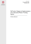
Fig. 1. Process communication by means of messages. In the example, B is the sender of a message to the receiver A. Sender and
receiver are identified by a process name of at most 11 characters.
Return parameters are underlined.
A:
WAIT MESSAGE(SENDER. MESSAGE.BUFFER IDENT)
SEND ANSWER (ANSWER. BUFFER IDENT)
B:
SEND MESSAGE ( RECEIVER, MESSAGE. BUFFER IDENT )
WAIT ANSWER. (ANSWER, BUFFER IDENT)
1106/I 108.
Boss 2 handles a m a x i m u m of 50 terminals, various
types of backing stores and magnetic tapes, printers,
readers, punch, plotter, and various process control
devices. The resources are available for all types of
service. Boss has a dynamic priority system based on
swapping and updates an estimate of the job completion
times taking into account all resources demanded by
the jobs. This estimate is available from the terminals.
All the facilities can be used with a core store from 32 k
words (of 24 bits) and a disk of 2 M words.
Performance measurements have been made on a
service center configuration with 20 terminals, 64 k
words of core store, and a small added drum. The jobs
are production runs and debugging of medium and
large data processing programs. During the six busiest
hours, the cpu-utilization is 40-50 pct used by jobs,
10-20 pct by the operating system and the monitor.
The average operating system overhead per job is 3
sec--including nonoverlapping I/o transfers in the
operating system. The response time to simple on-line
commands like editing is negligible (less than 0.5 sec).
During the first year of operation, the system
typically ran for weeks without crashes. Today it seems
to be error free.
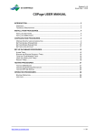
Fig. 2. Processes and coroutines. Processes are implemented by
the RC 4000 Monitor. Coroutines are implemented inside the single
Boss process. The set of coroutines is idealized.
BOSS PROCESS
DRIVERS
JOB PROCESSES
-C----1
// \
/
MESSAGE
COMMUNICATION
COROUTINES
COMMUNICATING
BY SEMAPHORES
MESSAGE
COMMUNICATION
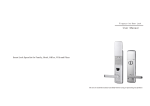
Fig. 3. All coroutines of Boss 2 and their communication. Some
peripheral devices are shown, too.
1.2 The RC 4000 S y s t e m Without Boss 2
Boss 2 runs under an extended version of the Monitor
(Nucleus) described in [2, 3, and 16]. The principles of
the Monitor may be outlined as follows.
The Monitor is a set of procedures which make the
computer appear as if it were executing several programs at the same time. The sequential execution of
such a program is called a process. Some of the processes are built-in drivers (external processes), some of
them are job processes executing a sequence of user
defined programs (job steps), and some of them are
operating systems.
Any two processes can communicate and synchronize by means of messages. Each process owns a set of
message buffers in the protected Monitor and it has a
message queue in which it can receive message buffers
sent to it from other processes (Figure 1). It can call a
Monitor procedure asking to wait until a message buffer
is in this queue, and it can return a message buffer to
the sender (send answer). Two other Monitor procedures allow it to send a message to another process
378
1,~u,~-p-
,
COMMUNICATIONS: =
Communications
of
the ACM
-
-DOG
i
PRIVATE BUFFER
~
QUEUE MULTI-BUFFER
LOCKING SEMAPHORE "=---SIMPLE MULTI-BUFFER
July 1975
Volume 18
Number 7
and wait for an answer to be returned. A further Monitor
procedure--essential for implementation of operating
systems--allows a process to wait for the first coming
message or answer (wait event).
A process owns a set of resources like working store
and message buffers. It can use a part of these resources
to create another process (a child) running in parallel
with the creator (the parent). Later the parent can
remove the child and get the resources back. A process
which is an operating system creates job processes in
this way.
The pragmatic rules for communication job/operating system and job/drivers were developed from 1969
to 1970, that is, before any advanced operating system
was planned. In this early period a lot of compilers and
utility programs were developed, and for compatibility
reasons Boss had to follow the old pragmatic rules.
During the period from 1969 to 1972 the computer
was mostly operated with an extremely simple operating system which handled core resident job processes
only. The creation and removal of job processes was
always ordered manually and executed immediately or
rejected (i.e. no job queue existed in the computer).
A job process could send two kinds of messages: input/
output messages to the drivers and parent messages to
the operating system. The input/output messages asked
for operations very close to the hardware, like transfer
of a data block or position of a magnetic tape. Input/
output strategies and error recovery were mostly handled
by the user programs and the library procedures. The
parent messages asked for a variety of functions like
mount a magnetic tape, mount a paper tape, terminate
the job, abort the job step in at most x seconds, print
an operator message.
The simple operating system simply printed all
parent messages on a console without trying to understand them. Although it was quite convenient to handle
tape mounting and paper tapes in this way, the method
was unsuited for handling files on disk (open file, create
file, etc.). A major fault in the early design was that
file handling was not communicated as parent messages
--with automatic handling in the simple operating
system. Instead a special set of monitor procedures was
supplied, which did not even use the message mechanism. As a result, later operating systems could not
"catch" the file handling requests, and disk allocation
strategies became limited by the monitor.
1.3 The Place of Boss 2 in RC 4000
These were the conditions upon which we started
the development of Boss 2. We would not change the
existing software unless strictly necessary. However, we
soon found it necessary to modify and extend the file
handling procedures in the monitor, and this project
developed in parallel with Boss 2 [16].
Figure 2 shows the process Boss which executes the
Boss 2 program. The job processes are children of Boss.
Boss receives messages from the job processes and sends
379
the answer when the requested operation is completed.
Of course the jobs send all parent messages to Boss,
but some input/output messages are also sent to Boss,
because Boss simulates some devices and behaves like
a set of drivers toward the job. The devices simulated
are very slow devices requiring spooling and devices
difficult to share (low speed terminal, paper tape reader,
printer). The job sends input/output messages directly
to the drivers for fast devices like disk and magnetic
tape.
Boss sends messages to various drivers either to
complete the device simulation (terminal, reader,
printer) or to execute a parent message (reading a
magnetic tape label in connection with the parent
message "mount magnetic tape").
Inside Boss, a set of parallel activities is going on:
one activity synchronized to each job and one synchronized to each peripheral device (i.e. to the driver).
These activities will, in principle, communicate with
each other as shown in Figure 2. Each activity could
have been implemented as a process under the monitor,
but in an unsuccessful project (Boss 1) we had learned
that processes and messages were completely unsuited
for the purpose.
The major problem is that each process has its own
message queue. For instance it is not possible to let a
message queue represent a pool of free records--common to several processes--because only one proce 3
can get messages from the queue. For the same reason,
Dijkstra's semaphore construction for critical regions
cannot be made directly with messages. It would be
possible to solve these problems by introducing an
administrator process, but its logic would be complicated.
Other problems are that RC 4000 processes are
very difficult to make reentrant, and they cannot readily
share code or data tables, especially when swapping or
paging is used.
Finally, only 23 processes plus drivers can be created
in RC 4000, and we needed more than a hundred parallel
activities inside Boss. So in all cases we would have to
simulate more parallel activities inside one process.
The solution we chose was another level of multiprogramming running inside the single Boss process.
The monitor of this "multiprogramming system" is
called the Boss 2 Central Logic, the parallel activities
are called coroutines, and the communication and
synchronization is done by means of simple semaphores
and queue semaphores as explained in the sequel. The
coroutines run in a virtual memory simulated by the
Central Logic and with the core store areas of the job
processes considered special pages. The synchronization
to the surroundings (replacing interrupts in a conventional multiprogramming system) is handled by means
of the monitor procedure "wait event," which allows
the Central Logic to wait for the first answer or message
(the first "interrupt").
Below we will discuss the coroutines and show why
Communications
of
the ACM
July 1975
Volume 18
Number 7
the Deadlock problem changes the idealized picture of
Figure 2 to the actual one in Figure 3.
The design is shown to be governed by the parallel
activities (one synchronized to each j o b and one synchronized to each peripheral device). A hierarchical
structure of the parallel activities is imposed afterward
in order to prevent Deadlock.
Fig. 4. Process (or coroutine) communication by means of aueue
semaphores. The queue semaphores have no fixed relation to the
processes, and in principle any process may wait for or signal (send
into) the queue. When A or C has received a record, they will later
return it to a separate queue of free records (not shown), la can then
get a new record from this queue.
A: OR C:
WAITQ (SE MAPHORE, RECORD)
B:
SIGQ(SEMAPHORE.RECORD)
2. Coroutines and Semaphores
SEMAPHORE
2.1 Basic Coroutine Scheme
Each coroutine of Boss will perform an activity with
a speed determined by a peripheral device or a j o b
process. Typically, the following activities will be in
progress simultaneously:
a. Printing data from the disk to the line printer--as
fast as allowed by the printer (performed by the coroutine "ps-printer").
b. Reading data from card reader to the d i s k - - a s fast
as allowed by the reader and the operator (coroutine
"ps-card").
c. Communicating with a user terminal about editing,
file listing, etc. (coroutine " c o m m a n d i o 1").
d. Communicating with a second user terminal (coroutine " c o m m a n d i o 2").
e. Performing a user job, i.e. handle the messages sent
from the j o b process to Boss (coroutine "ps-job 3").
f. Performing a second user j o b (coroutine "ps-job
4").
The coroutines may be thought of as parallel processes,
the only essential difference being the rigid scheduling
of cpu-time.
The coroutines use only a little cpu-time and disk
time, and as a result they need not delay each other.
Of course, an activity like (a) above may run out of
data to be printed, and then it will have to await the
arrival of new data from activities like (e) and (f).
In general, the algorithm executed by a coroutine
follows this basic scheme:
Step 1. Wait for a request to do some work.
Step 2. Send a finite number of requests to other coroutines or drivers.
Step 3. Answer the request of Step 1.
Step 4. Send a finite number of requests to other coroutines or drivers.
Step 5. G o to Step I.
F o r a ps-printer (activity (a)), Step 1 waits for a
request to print some data. The requests are sent from
other coroutines by means of semaphores, and in busy
periods several requests may be queued up. Step 2
sends requests to the printer driver in the form of
messages and awaits the answers. When there are troubles with the printer, Step 2 may also send requests to
the operator. Step 4 is blind.
F o r a ps-job (activity (e) and (f)), Step 1 waits for a
380
message from the job process or a request from the
operator's or user's terminal. Steps 2 and 4 depend on
the actual request, and they may involve requests to a
variety of coroutines and drivers.
In general, a coroutine waits for a request in Step I
and for answers to requests in Steps 2 and 4. This is
accomplished by calling the Central Logic, which returns to the coroutine in case the request or answer is
ready. If it is not ready, the Central Logic returns to
another coroutine which is ready to run, or it calls the
monitor function "wait event." Section 4.2 elaborates
on this topic and on the use of reentrant code to implement identical activities like (e) and (f).
The size of the coroutine algorithms varies considerably: "rewinder" is just 30 instructions, " p s - j o b "
and " c o m m a n d i o " are several thousand. Thus coroutines are not a partition of the code into manageable
pieces. Rather they reflect the external requirements to
parallel action. Notice, that if we want the basic scheme
above and want to run all peripherals and all jobs in
parallel, we need at least one coroutine for each periph-
eral and each job.
2.2 Queue Semaphores
The communication and synchronization between
coroutines is done by means of queue semaphores and
simple semaphores. A queue semaphore is an abstraction
which represents a queue of records or a set of coroutines waiting for records to be put in the queue
(Figure 4).
Two procedures of the Central Logic handle the
queue semaphores:
waitq(semaphore, record) :
The procedure "wait queue" removes the first record
from the queue represented by the semaphore. A
pointer to the record is returned to the calling coroutine. I f the queue is empty, the calling coroutine is
suspended--waiting until a record is available in the
queue.
sigq(semaphore, record):
The procedure "signal queue" inserts a record
(specified by a pointer) into the queue of the semaCommunications
of
the ACM
July 1975
Volume 18
Number 7
phore. If coroutines are waiting for records in the queue,
one of them will be activated and it will run later.
The main difference between queue semaphores
and messages is that a queue semaphore does not belong to a single process (or coroutine). In principle,
any coroutine may wait for or signal any queue semaphore. Another difference is that the records may have
any length, while the message buffers are restricted to
eight words.
When coroutines communicate, two semaphores
are involved. One semaphore holds the requests, the
other the answers.
As an example, consider the communication between a ps-job and a ps-printer. The requests are
queued by the semaphore "print queue," and a request
record specifies that a certain file should be printed.
The free records are queued by the semaphore "print
free." Now the ps-job uses the basic scheme in this
way:
Step 1. Wait for a request from job, operator, or user.
Step 2. if request is print a file then
begin waitq(print free, record);
store print request in record;
sigq(print queue, record);
end;
Step 3 . . . .
The ps-printer uses the basic scheme in this way:
Step I. waitq(print queue, record).
Step 2. print the file using send message and wait
answer.
Step 3. sigq(print free, record).
Step 5. goto step l;
Note that these algorithms cause waiting in the proper
way. When no free records are available, the ps-job
will wait on "print free" in Step 2. When no requests
are in the queue, the ps-printer will wait on "print
queue" in Step 1.
If several printers exist, each of them is served by
its own ps-printer. Any printer may print a file. This is
obtained automatically if "print queue" is common to
all ps-printers. As long as "print queue" is nonempty,
all printers will be busy. This simple implementation of
parallel request processing is difficult to obtain with
most other communication methods. For instance,
messages are completely unsuited for that purpose.
The communication principle corresponds to the
beautiful, symmetrical producer-consumer algorithm
of Dijkstra: the ps-job consumes free records and
produces requests. The ps-printer consumes requests
and produces free records. The principle can also be
thought of as a generalization of the conventional
double buffer scheme to multi-buffers. (A record corresponds to a buffer.) In Figure 3, 4 double arrows
show such multi-buffer communication based on queue
semaphores. The arrow shows the direction of the request.
381
2.3 Simple Semaphores
Simple semaphores were introduced by Dijkstra
[5, 6]. They resemble queue semaphores, but the queue
is not represented explicitly. Only a count of the records
in an abstract "queue" is kept track of.
Thus, simple semaphores can be used to implement
queues where the records are linked in a user defined
manner or where the record does not contain essential
information.
Simple semaphores are handled by the following
two procedures of the Central Logic:
wait(semaphore)
sig(semaphore)
It is assumed that coroutines follow the discipline of
handling a semaphore either with waitq/sigq exclusively
or with wait/sig.
As an example, consider the handling of output from
a job to the terminal. Each request consists of one word
to be printed (3 characters), and an ordinary queue
would be too cumbersome. Instead the ps-job and the
"termout" agree to use a backing store area in a cyclical
manner. Two simple semaphores represent the number
of full and free words, and the algorithms look exactly
like those originally proposed by Dijkstra. Multi-buffers
implemented in this way appear as dotted arrows in
Figure 3.
As another example, we will elaborate on the parallel
printers of Section 2.2. In practice we want to sort the
files according to paper type (one copy, two copies,
special forms, etc.) in order to minimize paper changing. So we use one queue for each paper type and a
common abstract queue representing the total number
of print requests. The abstract queue is implemented by
a simple semaphore "common print." Now the ps-job
sends a print request in this way:
Step 2.
waitq(print free, record);
store print request in record;
sigq(paper type queue, record);
sig(common print) ;
The ps-printer proceeds like this:
Step 1.
wait(common print);
if queue of current paper type is empty then
begin select a non-empty paper type queue (at
least one exists) according to some strategy;
current paper type := queue selected
end;
waitq(current paper type, record);
Step 2 . . . .
Note that selection of current paper type is a critical
region which should be executed by at most one psprinter at a time. Otherwise two ps-printers could
decide to wait for the same paper type queue, which
happened to contain only one request.
Communications
of
the ACM
July 1975
Volume 18
Number 7
2.4 Critical Regions
A critical region is a part of an algorithm which
updates variables common to several processes (or
coroutines). If a certain relation is to be maintained
between the common variables, one process must
complete the critical region before another process can
enter a critical region working on the same variables.
A sound solution is to use a queue with one record
which contains the c o m m o n variables. When a process
wants to update the variables, it gets the record by
means of waitq. After the updating it returns the record
to the same queue by means of sigq. If other processes
want to update the variables meanwhile, they will be
suspended when executing waitq.
Because only one record is involved, its address
may be known to all processes, and a simple semaphore
may replace the queue semaphore. This was the solution described by Dijkstra, and it is also used in Boss.
The corresponding locking semaphores are shown in
Figure 3 as waved arrows.
The special coroutine scheduling of cpu-time allows
a simpler handling of critical regions in many cases:
the Central Logic can only pass control to another
coroutine when a coroutine explicitly waits. As a result,
critical regions without embedded waiting can be
handled without semaphores. This simplifies programming in m a n y cases, for instance in the printer case of
the preceding section.
2.5 Private Buffers and Messages
A special case of multi-buffer communication is
frequently used. Each sender of a request has his own
record, and he wants the answer to be returned through
his private semaphore, which may be simple. The
private semaphore is specified in the request. The sender
uses the basic scheme in this way.
Step 2 or 4. sigq(request queue, private record);
wait(private answer semaphore);
Because all the algorithms are loops, you may think of
the scheme in a rotated form with wait preceding sigq.
Then it looks again like the producer-consumer algorithm.
The receiver uses the basic scheme in this way:
Step 1. waitq(request queue, record);
Step 3. sig(record [private answer[);
This private buffer communication corresponds
exactly to the message/answer communication with the
drivers. In Figure 3 they are all represented by normal
arrows.
3. Deadlock and Hierarchical Structuring
3.1 Absence of Deadlock, Basic Proof
We can prove the absence of Deadlock in Boss by
proving that no coroutine waits forever when it has
382
useful work to do.
In the basic scheme of Section 2. I we can distinguish
two kinds of waiting. Waiting in Step 1 for a request is
idle waiting. If the coroutine waits forever here, it does
no harm as it then has no work to do. Waiting in Step
2 or 4 is answer waiting. If the coroutine waits forever
here, we have a Deadlock as it will not be able to process
the requests.
In Figure 3 all requests go from right to left, and
we can then prove by induction that all requests are
processed in a finite time: All "coroutines" to the
extreme left are drivers which by definition complete
their operation in a finite time (at least if they are
handled properly by the operator). N o w it follows that
coroutines in column 2 from the left terminate their
Steps 2 and 4 in a finite time, and hence they produce
the answer (Step 3) in a finite time. If the request queue
is implemented as First-In-First-Out or any other kind
of fair scheduling, we have then proved that all coroutines in column 2 answer a request in a finite time.
We can now proceed to column 3, and so on, until
absence of Deadlock has been proved for every coroutine.
Note that data may flow in the same direction as
the request (e.g. for a printer) or in the opposite direction (e.g. requests for paper tape input).
In the next section we will tackle the Deadlock problems originating from locking semaphores and other
deviations from the basic coroutine scheme.
The requirement that "all requests go from right to
left" is a very strong design criterion. In some cases it
has caused a coroutine synchronized to a single peripheral device to be split up in two.
This has happened with terminals which have a twoway initiative: The job may request input or output from
the terminal, and this is handled by the coroutine
" t e r m o u t . " The user may also request actions f r o m the
system while his job is running. For instance he may
want a print out of the job state or the job queue, or he
may ask the system to kill the job. This is handled by
the coroutine " c o m m a n d i o . " As the two coroutines
share the terminal, they use a locking semaphc..'e to get
exclusive terminal access during a conversation.
In Figure 2 the system is shown with only one coroutine to handle a terminal, but then we have requests in
both directions to the ps-job. As a result we would risk
Deadlock, because the terminal coroutine could wait for
an answer from the ps-job, while the ps-job waited for
an answer from the terminal coroutine. N o n e of them
would then be able to process the request f r o m the
other.
Also magnetic tape stations have a two-way initiative, because Boss may try to rewind the tape (the coroutine "rewinder") while the operator unloads it and
mounts a new tape (the coroutine "remoter").
Because all communications are symmetrical producer-consumer algorithms, the direction of the request
may seem rather arbitrary. However, it is well defined
Communications
of
the ACM
July 1975
Volume 18
Number 7
from a semantic point of view. For instance if the psprinter does not get a request, it is because no printing
is needed. But if it does not get an answer, printing is
needed but not carried out.
In some cases we could imagine a system with a
reversed request direction. For instance, we could try to
construct a system where the tape reader issued a request
whenever a paper tape was inserted. We could then try
to prove that all tapes were loaded sooner or later. In
the present system we can only prove that a job requesting a tape will be able to progress sooner or later.
3.2 Absence of Deadlock, Special Cases
The basic coroutine scheme does not explicitly mention the use of locking semaphores to control critical
regions. So we will have to prove separately that no
coroutine waits forever to enter a critical region.
When a coroutine has two or more nested critical
regions, all other coroutines must use the same sequence
of nesting. Then the entering into an inner critical region
cannot be delayed endlessly by another coroutine being
in the same critical region.
If a coroutine awaits an answer inside a critical region, the producer of the answer may not require entrance to the same critical region. This rule propagates
recursively, as the producer of the answer may not even
await an answer from another coroutine using the same
critical region.
Thus the locking semaphores create two rules to be
followed (and proved) in each coroutine.
Next we will discuss a more serious deviation from
the basic coroutine scheme: In some cases a coroutine
does not produce the answer in Step 3 until it has gotten
other requests in Step 1. The proof methods used here
vary from case to case.
As an example consider the coroutine "request display," which prints operator requests and maintains a
list of operator requests which have not yet been completed. Operator requests are messages like "mount
magnetic tape" or "change paper." The list of incompleted requests can be printed on demand.
The request display receives two kinds of requests.
One is "insert," which specifies an operator request to
be printed and kept in the list. This request is not answered in Step 3. The other kind is "delete," which specifies that a request should be deleted from the list--presumably because the operator action is completed. In
this case Step 3 answers both the delete request and the
earlier insert request.
The proof that all requests are eventually answered
involves two rules. First, the operator is supposed to
honor a request in a finite time and this must cause a
"delete" to the request display. The second rule imposes
a limit on the number of "insert" requests which a
coroutine may have pending. This limit is one for each
ps-printer, ps-reader, and ps-job with addition of one
for each tape station (to be used either by the ps-job
or the remoter). The limit is zero for all other corou383
tines. If these rules are followed by every coroutine, we
prevent Deadlock simply by making a sufficiently large
pool of free request records.
As a more important example consider the coroutine
"Banker," which allocates resources to the jobs. When
a coroutine wants to reserve or release resources, it
sends a private buffer (Section 2.5) to the Banker stating
the set of resources involved. It gets the answer to a release request immediately, and the answer to a reserve
request when the resources are available. Again, the
Banker may skip the answer in Step 3 until more resources have been released. The proof in this case is
somewhat complicated and assumes that the maximum
set of resources needed by a job is stated at job start. The
allocation algorithm and details of the proof are given
in [11].
We should mention that the Banker is the only coroutine not synchronized to a job or a peripheral device.
In fact the Banker is superfluous as a coroutine, and it
could be replaced by a reentrant procedure which is
called by any coroutine wanting to reserve or release resources for a job. The solution would then become the
"private semaphore" scheme described by Dijkstra [5].
Later, Dijkstra has proposed the private buffer scheme
actually used in Boss (the "Secretary" of [7]).
During the debugging we met some Deadlocks
caused by trivial programming errors (e.g. waiting for
a wrong semaphore) and one Deadlock caused by violation of the second rule for locking semaphores (easily
corrected by splitting the critical region in two).
3.3 Hierarchical Structuring and Coroutine Structuring
The basic proof of Deadlock absence is equivalent
to that of Dijkstra and H a b ~ .rlann [5 and 9]. Especially,
the idle waiting in Step 1 corresponds to their "homing
position."
If we wish it, we could regard the set of coroutines
as structured in a hierarchy like Dijkstra's. Each column
of coroutines would then correspond to a level of the
hierarchy. But this is not the way things developed.
A hierarchical structuring is usually invented during
the construction process. This we have done inside each
coroutine, by arranging the program in nested parts and
procedures in the usual manner.
Contrary to this, the structuring into coroutines is
mainly determined by the external requirements. The
general rule seems to be this: Make one coroutine (or
process) for each independent stream of external events.
In our case, each job process and each peripheral device
supplies an independent stream of events. Devices with
a two-way initiative supply two independent streams of
events and are consequently handled by two coroutines.
(The only exception in Boss is the Banker, as discussed
in Section 3.2.) The structuring into columns comes
later and serves to guide the proof of Deadlock absence.
The author has used this structuring principle with
equal success in later projects like message switching and
remote process control. One additional rule has turned
Communications
of
the ACM
July 1975
Volume 18
Number 7
up: Assume that the processing of a critical event stream
requires much cpu or disk time. Then two coroutines
with an intermediate multi-buffer should be used in
order to overlap event receiving and processing: one
coroutine which receives the external events and one
which spends the cpu or disk time. The latter coroutine
may as well serve several coroutines of the first kind.
4. Implementation Principles
4.1 Virtual Store
The total space occupied by coroutine algorithms,
records, and other variables is much too large for the
core store. Instead, we implemented a virtual store
based on software paging.
Each word in the virtual store is identified by a 22bit virtual address. The lower range of addresses corresponds to resident parts of the virtual store--with the
virtual address being the hardware core address. The
middle range of addresses corresponds to virtual store
parts on d r u m - - w h i c h are transferred to the core store
upon demand. The high range of addresses is similar,
but corresponds to virtual store parts on a disk.
The virtual store is divided in sections, where each
section is a full number of physical blocks on the device
(block size equals 256 words of 24 bits). Whenever a
word of the virtual store is needed and it is not in the
core store, the entire section containing the word is
transferred. In practice we consider the virtual store as
divided in pages of consecutive words. A page is always
allocated inside a section to allow fast addressing of the
entire page after an initial page access. Several small
pages can be allocated in a one block section, whereas
large pages occupy a section each.
4.2 Coroutines
Each coroutine is represented by an 8-word coroutine description which is resident in the core store. One
of the words is used as a link, either to a semaphore
(when the coroutine waits for it), to the pager queue
(when the coroutine waits for page transfers), to the
active queue (when it waits for cpu-time), or to the
answer queue (when it waits for a driver answer). One
word is used for identifying the driver answer waited for,
or for working during operations on queue semaphores.
Five words contain virtual addresses, which represent
pages to be held in the core store while the coroutine
uses the cpu. A bit in each of these page description
words shows whether the page is modified by the coroutine so that it should be written back. The first page
description always represents the code page in which
the current coroutine algorithm is found. The last word
represents the return address to the coroutine. The address is relative to the beginning of the code page.
When a coroutine runs, the first five words of it~ current code page contain the absolute core addresses of the
five pages of its coroutine description. In this way the
384
code can easily access data in the five pages. Note that
the page allocation can only change when the coroutine
explicitly calls the Central Logic. The coroutine gets access to other pages by changing the coroutine description and then calling the Central Logic. In this case other
coroutines may run during the page transfers.
Reentrant coroutines are handled by allocating all
the variables in pages other than the code page. Thus,
two reentrant coroutines may run with the same code
page but different variable pages.
4.3 Semaphores
Each semaphore is represented by 3 core resident
words. One word is a count of the number of records or
- - w h e n negative--the number of coroutines waiting on
the semaphore. Two words point to the beginning and
the end of the record queue (or the queue of coroutine
descriptions waiting on the semaphore). This semaphore
representation is rather clumsy and could be replaced by
a one-word representation as shown in [15].
The records of a queue are pages in the virtual store
- - l i n k e d together through their first word.
4.4 Paging Method
As outlined above, demand paging is used. Of particular interest is the fact that several pages may be
needed simultaneously, and any page size (really section
size) may be used.
The core resident pager coroutine transfers pages
upon request from other coroutines. It will complete all
page transfers for one coroutine before it handles the
next coroutine in its request queue. It awaits the disk
and drum transfers as all other coroutines by means of
an entry to the Central Logic, thereby allowing the execution of other coroutines with all their current pages in
the core store.
The pager coroutine and the Central Logic maintain
a priority for each page in the core store. The priority
represents a least-recently-used strategy, but with regard
to pages presently used as I/O buffers or job processes.
The latter type of pages will have a very high priority
until the answer arrives or the job process is swapped
out by the Banker. The pager tries with a simple strategy
to allocate all demanded pages in low priority parts of
the core store.
5. Project Plan and Time Schedule
5.1 First Project Plan
The design of Boss 2 was started at Regnecentralen,
Copenhagen, in August 1970 by Klavs Landberg, Per
Mondrup, and the author. In October 1970 we completed the project specification as an internal report.
That part of the report which specified the facilities of
the first version and the possible later extensions was
published in March 1971 [13]. In this section, I will give
a summary of the project specification and explain the
Communications
of
the ACM
July 1975
Volume 18
Number 7
key estimates. In Section 5.4, I will compare it to the actual progress of the project.
The project specification was 25 closely written
pages. The facilities were described as follows. For each
type of peripheral device there was described the strategy to be used by Boss for handling it and the actions to
be taken by the operator. The devices considered were:
typewriter-like terminals, paper tape reader, printers,
several types of magnetic tape stations, several kinds of
drums and disks.
The on-line commands, the implementation, and
conventions for the on-line editor were outlined. Also
described were the resource allocation on backing stores,
the job scheduling and swapping strategies, the user
catalog, the account and statistics files.
One section estimated the storage demands and the
total system overhead.
A ten-page section described 21 major extensions of
the basic project to be decided before implementation
started. They included things like conversational jobs
(the basic version proposed only remote job entry combined with fast on-line editing), vdu-terminals, card
reader, remote batch terminals, and simple facilities for
process control experiments.
These parts of the report were published. The unpublished part (five pages) defined the extent of the
project, the preconditions, the time schedule, the use of
man-months and computer time, the cost for extensions
of the basic project, and the necessary implementation
group.
The extent of the project fixed the relations to other
parts of the software, accounting programs, writing of
manuals, transitions to maintenance, a n d - - o f course-the facilities as described above. Some facilities which
were not considered, but which might be important,
were pointed out.
The preconditions stated that certain other software
parts should be finished at certain times, that 76 hours
of computer time should be available for debugging,
that the extensions had to be decided and the specification accepted within a month.
A total of four persons (the three designers and
Bj~rn •rding-Thomsen) were assumed as the implementation group with a time schedule built on check points
as follows:
November 1970. Final decisions on extensions.
December 1970. Detailed specification of the internal
structure and the interface between all parallel activities
inside Boss.
February 1971. Debugged Central Logic. All other parts
punched.
May 1971. Prototype debugged.
July 1971. Installation of the prototype completed.
In view of the later facts that the prototype was
completed April 1972, and the first public release was
August 1972, this time schedule seems utterly ridiculous.
Let us see, however, how we arrived at it.
385
The key point was the estimate of the total number
of instructions. Our basis was the list of facilities and
strategies--not horrible--which we estimated as equivalent to our Algol compiler:
First estimate: Boss is 7,000 instructions.
From this the rest was deduced. An old rule of thumb
told that in a project from design to maintenance, a
programmer produced an average of 200 machine instructions a month. Thus 35 man-months were necessary.
Of these 6 were spent already with design (3 persons in
2 months), so 29 were left for 4 persons. This brought us
to June 197 I. We specified July to be cautious.
Another rule of thumb told that a good programmer
made one error or design fault for each 20 instructions
and that he could find one error for each test run. With
the debug technique we were accustomed to, a good test
run with succeeding careful inspection of the test output
could reveal about 5 errors. To be careful because of the
multiprogramming, we assumed that only half an error
could be found and corrected for each test run.
So the 7,000 instructions should give 350 errors and
700 test runs. The modular design of the system was
estimated to be sufficiently good so that the four programmers could work nearly independently of each
other, reducing the debug demand to 200 sessions at the
computer. We planned the debug sessions to 15 minutes
each, i.e. a total of 50 hours, and asked for 76. The main
debug period should be February, March, April (80
days), so two periods of 15 minutes a day should be
sufficient.
In order to utilize periods of 15 minutes, we planned
the debug sessions carefully, as explained in the next
section.
5.2 Planning a Debug Session
A new and extended version of the Monitor was to
be used together with Boss, so that a total exchange of
the software had to take place during each debug session. We devised a method for a fast exchange of the
system based on exchange of disk packs and swap of
drum contents to the disk.
A special autoload paper tape was used to switch at
the beginning of each session, and another tape was
used to switch back to the end of the session. This took a
total of 5 minutes.
When we had used this system for a few weeks, we
happened to load the start tape at the end of the session
- - a n d the entire standard system disappeared and had
to be loaded from magnetic tape. The computer staff
responded by only allowing us run time in the night
after saving the standard system on tape. We responded
by changing the autoload tapes to one which itself found
out which of the two actions to perform. After a while
we regained our short periods of day time.
After reduction for the switch time, we were left with
10 minutes of which we wanted to use four times 1 minute for the planned translation and test of the four pro-
Communications
of
the ACM
July 1975
Volume 18
Number 7
grammer's parts. The 6 minutes left were spares for rush
corrections. In order to translate and generate a new
version in half a minute, all files had to be on disk and
only a small text file had to be translated into binary
form. No linker (loader) exists in RC 4000, so we had to
implement a special linker which loads the binary files
into the virtual store in which Boss runs. A simulation
program was also devised to feed Boss with input lines
from "terminals", etc., in the 30 seconds left.
We used the well-proven technique of permanent test
output [17] from all parts of Boss, so that the result of a
test run was a list of test output for later inspection of
what had happened. This test output is still used in the
normal production run, where it is stored on disk or
magnetic tape for analysis if the system breaks down
[14, Chap. 9, Installation and Maintenance]. A test output record is generated by the Central Logic whenever a
coroutine executes sig, wait, etc. Some coroutines also
produce private test output records showing intermediate results.
Obviously, listing of source programs were the exception rather than the rule. With a careful marking of
all corrections in the latest listing, we had no troubles
finding our way in the latest version. An important point
was the use of an extremely careful programmer--Isabella Carstensen--for the clerical work of keeping track
of paper tape corrections, keeping track of on-line rush
corrections, punching correction tapes according to
pencil marks in the listings, arranging safety copies, etc.
This work was drastically underestimated in the planning
stage.
Finally, the system of project file directories and
private file directories (planned for the extended monitor) was utilized in the debug sessions to assure that one
test file could b e tested together with reasonably good
versions of the other files [14, Section 4.6.3, User's Manual]. The decision that a private file was reasonably good
and could be made a project file had to be taken between
debug sessions after careful inspection of the test output.
5.3 Choice of Programming Language, Paging
The author had previously been involved in the
development of Boss 1 in Algol 5 for RC 4000. Although
Algol 5 was sufficient for the purpose, the necessary use
of reentrant coroutines was very cumbersome to express
in Algol. Worse, however, was that the object code
turned out to be 4 to 5 times longer than equivalent
handwritten assembly language code. With the same
overhead in page transfers this would need 4 to 5 times
more core store.
It should be noted that the Algol 5 compiler generates fairly good code. For instance it is claimed that
Algol W on mr~ 360 generates very efficient code, but investigations have shown [1] that it is just as long as
Algol 5 code.
As the long object code was prohibitive for the goals
of Boss 2, assembly language was chosen.
386
From the beginning it was assumed that the code and
variables of Boss were to be in a virtual store controlled
by a software paging system. RC 4000 has no hardware
for paging, so software page references must be inserted
where needed. We had experience with this kind of software paging from several Algol compilers. The main
problem was the hand-written standard procedures which
had to fit into a few of the fixed size pages. Whenever
changes were needed, it caused great troubles to fit the
new version into the fixed size pages. Another problem
was a lot of difficult paging bugs caused by code which
had brought a page to core and later referenced it with
an absolute address when it was possibly not in core
any more.
We solved the first problem by designing the paging
system for variable length pages. We partially solved the
second problem (paging bugs) by allowing a coroutine
to specify that an entire set of pages had to reside in core
simultaneously when it was running.
5.4 Actual Time Schedule
The first check point on the time schedule concerned
the final decisions on extensions. They were delayed 6
weeks due to disagreements between the user groups.
The extensions chosen were vdu-terminals, card reader,
job controlled selection of print forms, printer back-up
on magnetic tape. According to the project specification,
this should delay the installation by three months (of
which 6 weeks were due to the delay of the decision).
The next check point was apparently reached on
schedule with release of the report "Boss 2, Internal
Structure" dated January 1971. However, a close reading of the report reveals many missing details in the
interface between the coroutines. The report contained
a detailed version of Sections 2, 3, and 4 of this paper.
In March and April 1971 the company changed their
development policy, claiming that they would neglect,
somehow, the RC 4000 and try to find other areas for
the development groups. The Boss 2 group was heavily
involved in these discussions and a delay of one month
was accepted. The new schedule looked like this:
May 1971. Debugged Central Logic. All other parts
punched.
September 1971. Prototype debugged.
November 1971. Installation completed.
The Central Logic was debugged on schedule, but
most other parts were still not written. A lot of detailed
revisions of the schedule were made, but none of them
reflected reality. Several parts were completed and debugged, and around July 1971 about half of the system
was in the test phase.
A general reluctance to face the facts caused m e - - a s
a project manager--to discard all planning and just let
the group implement as fast as possible. Around August
1971, the group was augmented with Bo Jacoby and Bo
Tveden Jorgensen, and the responsibilities of the group
Communications
of
the ACM
July 1975
Volume 18
Number 7
were extended to also cover some related software projects excluded in the project specification.
In January 1972 everything was in the test phase, but
some parts were in a preliminary version. This point
most likely corresponded to the check point "All Parts
Punched," but the delay was 8 months.
In January 1972 we finally detected the real reason
for the delay. We had programmed 20,000 instructions
instead of the estimated 7,000. When the project entered
the maintenance stage in August 1972, we had programmed 26,000 instructions (including a few further
extensions).
The prototype was put in operation in April 1972.
Further extensions for conversational jobs (time sharing) and process control were implemented until August
1972, when the first public release took place. At that
time 115 man-months had been used instead of the
latest estimate of 55 man-months.
5.5 Conclusion
The main fault in the estimates was that the number
of instructions were underestimated by a factor of 3
(excluding contributions from later extensions). A possible cause for this--pointed out by Peter Naur--is that
we initially compared the project to an Algol compiler
which used a very advanced table technique to bring
down the program length [17]. A similar technique was
not used in Boss, possibly because we concentrated too
much on the structuring into coroutines and forgot to
design the sequential algorithms inside each coroutine
in the same careful manner. Another cause may be that
each facility and strategy were conceived and implemented individually, whereas an Algol compiler benefits from the extremely homogeneous structure of Algol
60.
A secondary reason for the underestimate was the
interface to the Monitor. The Monitor was extended in
the same period with several facilities needed by Boss.
Especially the interface concerning drum and disks was
much more complicated to utilize than anticipated. This
problem was felt severely during the development and
caused major revisions of Boss and the Monitor.
A minor contribution to the underestimate is the late
inclusion of further extensions and related projects (user
catalog updating, accounting, process control, etc.).
A main fault in the project management (the author
primarily) was the sticking to a time schedule instead of
revising the more fundamental estimate of the number
of instructions. It is typical that the main influence of
the underestimate is in the programming phase. The
debug phase and the installation phase were not so significantly affected.
The rule of thumb saying 200 instructions per manmonth may now be checked for the actual schedule:
26,000 instructions/115 man-months = 230.
What might have helped us in the planning was a
similar rule of thumb for the programming phase alone.
.387
6. Evaluation
6.1 Performance
The facilities as originally specified were implemented, sometimes in an extended version. We dropped
one extension--the vdu-terminals--because the hardware was not developed. Another extension--printer
back-up on magnetic tape--has not been put in operation, partially because there seems to be no serious need
for it.
The backing store and core store requirements are in
good agreement with the specification. However, the
system overhead was somewhat underestimated. When
Boss runs in the specified core area (15,000 characters),
the overhead is many times more than estimated because
of thrashing. When Boss uses 30,000 characters in the
core store, the overhead is 1.5 times the estimate (actually 3 seconds overhead to execute a job). The larger
core demand is related to the code being 3 times longer
than estimated. The factor 1.5 could easily have been
anticipated if a more detailed analysis was carried out in
the specification phase.
6.2 Reliability, Bugs, Proof
When we started the Boss 2 design, we knew that
the RC 4000 software was extremely reliable. In a university environment, the system typically ran under the
simple operating system for three months without
crashes. Although some errors existed in compilers and
utility programs, they affected, at most, one job. The
crashes present were possibly due to transient hardware
errors. Errors in the peripherals were more frequent, but
did not wreck the rest of the system.
From the beginning, we aimed at a similar stability
for Boss six months after release. So we did not implement any restart facilities, except that the permanent
files on disk were preserved by a simple strategy. We believe that this decision is a major reason for the relatively
simple and stable operating system.
In fact, Boss 2 passed a 3-week delivery test in September 1972--one month after the first release. In these
3 weeks the contract allowed at most four crashes because of hardware or software. Actually four crashes
occurred, three of them caused by bugs in Boss. In the
period the system was heavily loaded with unrestricted
user jobs: program debugging, process control jobs, and
conversational jobs.
From September 1972 to March 1973, dozens of
errors were reported as the users explored the corners
of the system. In April 1973 all reported errors, except
one, were located and corrected. Today the system seems
to be error free. The corrections nearly always converged
in the sense that one correction did not cause errors
somewhere else.
We have collected all corrections during the development and maintenance, but we have not done statistical analysis on them. Nearly all errors are simple programming errors that occur also in uni-programming
Communications
of
the ACM
July 1975
Volume 18
Number 7
(loading a wrong register, testing a wrong condition).
The most difficult bugs to find were associated with paging (paging bugs, see Section 5.3), and the correct return of borrowed resources (see below).
A few bugs were typical multiprogramming bugs:
forgetting to reserve a resource which then happened to
be used by another coroutine at the same time. One case
of Deadlock occurred (see Section 3.2), but it was simple
to correct.
The only important design faults were those associated with booking of resources on the backing store and
parallel access to files. I am afraid we still have only a
superficial knowledge of these problems (see [16]).
The successful detection and correction of errors
after release of the system could not have been achieved
without the permanent test output (Section 5.2). If the
system broke down, the computer staff would send the
test output file to the project group, which then was able
to find the error in most cases. As normally only a short
backing store file (80,000 characters) is used for cyclical
collection of test output, some errors were still difficult
to find because they occurred a long time before the
symptoms. For instance, if a resource is borrowed and
later only a part of it is returned, it will take a long time
before something wrong becomes apparent. The cause
is then not available in the test output. In the cases where
we have had test output on magnetic tape (one large
reel every three hours), we have always been able to
locate the error--possibly by means of an ad hoc program for analyzing the tapes.
The prototype was very carelessly tested, but after
it had been put in operation nobody had time to make
careful, systematic test programs. I believe that if the
prototype had been delayed some months, we could
have found most errors via systematic test programs.
The question of proving an operating system is sometimes discussed. We have proved some statements about
the system, for instance the absence of Deadlock. However, in order to prove the entire system, we would have
to formalize every statement in the manuals (120 pages)
and prove them. Still I doubt whether a statement like
"absence of Deadlock" would have emerged from the
manuals. It seems to me that the only systems which can
realistically be proved are those where the entire manual
is below, say, 10 pages.
Acknowledgments. The design of Boss 2 is due to the
exciting collaboration of Per Mondrup, Klavs Landberg, and the author. The implementation is due to the
hard work of the project group consisting of Isabella
Carstensen, Bo Jacoby, Bo Tveden J0rgensen, Bj0rn
9rding-Thomsen, and the three designers. The author
had the overall project responsibility until June 1972
when Klavs Landberg took over the job.
I would like to thank Peter Lindblad Andersen and
Hans Rischel for their patient development and modifications of the Monitor and the utility programs.
An independent project run by Ole Caprani, Lise
388
Lauesen, and Flemming Sejerghrd Olsen extended the
system to serve also as a remote batch terminal for CDC
6400 and Univac 1106.
Finally, we are very indebted to Christian Gram, our
manager, for his patience and encouragement, especially
during the exhausting winter 1971-72.
Received October 1973; revised October 1974
References
1. Andersen, J., Moiler, T., Ravn, A.P., and Stamp, S. Rapport
over Effektivt K0rende Algol System (in Danish). Projekt 71-9-7.
Datalogisk Institut, U. of Copenhagen, 1972.
2. Brinch Hansen, P. The nucleus of a multiprogramming system. Comm. ACM 13, 4 (Apr. 1970), 238-250.
3. Brinch Hansen, P. RC 4000 Software, Multiprogramming
System. RCSL No. 55-D140. Regnecentralen, Copenhagen, 1971.
4. Denning, P.J. Third generation computer systems. Computing
Surveys 3, 4 (Dec. 1971), 175-216.
5. Dijkstra, E.W. The structure of the"THE" multiprogramming system. Comm. ACM 11, 5 (May 1968), 341-346.
6. Dijkstra, E.W. Cooperating sequential processes. In Programming Languages, F. Genuys (Ed.), Academic Press, New York,
1968, pp. 43-112.
7. Dijkstra, E.W. Hierarchical ordering of sequential processes.
In Operating Systems Techniques, C.A.R. Hoare and R.M. Perroth
(Eds.), Academic Press, London, 1972.
8. Habermann, A.N. Prevention of System Deadlocks. Comm.
ACM 12, 7 (July 1969), 373-377, 385.
9. Habermann, A.N. On the harmonious cooperation of abstract
machines. Technische Hogeschool, Eindhoven, 1967.
10. Horning, J.J., and Randell, B. Process structuring. Computing
Surveys 5, 1 (Mar. 1973), 5-30.
11. Lauesen, S. Job scheduling guaranteeing reasonable turnaround times. Acta lnformatica 2 (1973), 1-11.
12. Lauesen, S. Program control of operating systems. BIT 13,
3 (1973), 323-337.
13. Lauesen, S. Forel0big Specifikation af Operativsystemet Boss
2 (in Danish). RCSL No. 55-D153. Regnecentralen, Copenhagen,
1971.
14. Lauesen, S. Boss 2, user's manual, operator's manual,
installation and maintenance. RCSL No. 3l-D21 i, 31-D230, and
31-D191, Regnecentralen, Copenhagen, 1972.
15. Lauesen, S. Implementation of semaphores and parallel
processes. NBB Doc. EC-D4, Nordisk Brown Boveri, Copenhagen,
1973.
16. Lindblad Andersen, P. Monitor 3. RCSL No. 31-D109.
Regnecentralen, Copenhagen, 1972.
17. Naur, P. The design of the Gier Algol Compiler. BIT 3
(1963), 124-140 and 145-166.
18. Baker, F.T. Chief programmer team management of
production programming. IBM Syst. J. 1 (1972), 56-73.
Appendix A. Survey of Coroutines in Boss
The list below refers to Figure 3 and mentions all coroutines in a row by row sequence.
Request Display. Prints messages to the operator on
the main console. Messages demanding action f r o m the
operator are kept until the action is completed (Section
3.2).
Commandio. One commandio to each on-line terminal and to the operator's console. Performs all conversation with the on-line user and the operator, including
editing and listing of files. Some commands are passed
on to other coroutines (commands like "run j o b , " "kill
j o b , " "start printer").
Termout. One termout to each on-line terminal.
Communications
of
the ACM
July 1975
Volume 18
Number 7
Prints job output on the terminal from a multi-buffer on
disk. For nonconversational jobs the progress of the job
is not delayed by the slow terminal.
Ps-printer. One ps-printer to each physical printer.
Prints completed files from the backing stores or job
controlled output from a multi-buffer. Attempts to minimize change of paper type (see Section 2.3). Communicates with request display about change of paper, etc.
Tape Printer. May copy print files from the backing
store to a magnetic tape. When the backing store is about
to run full of print files, the tape printer asks the operator for a tape and copies the files.
Ps-job. One ps-job to each on-line terminal plus
spares for execution of batch jobs and internally generated jobs. A ps-job interprets the job specification
(the first job control command), loads possible data
files from card or paper tape, reserves most of the temporary resources for the job, and creates and starts the
job process.
Now the ps-job receives messages from the job process (all parent messages and some input/output messages). Some messages are checked and then passed on
to other coroutines (e.g. print a backing store file, write
special operator request). In the same queue the ps-job
receives certain buffers from commandio ("kill job,"
"answer to special operator request"), from remoters
(tape ready), and from timer (time exceeded). Messages
which will cause a longer waiting time cause the ps-job
to ask the Banker to swap out the job meanwhile.
When the job is finished, the ps-job cleans temporary
files, asks for rewind of tapes, produces account records,
etc.
Job. The job process. In a given moment only some
of the ps-jobs have associated job processes.
Unknown Sender. Receives messages from unlogged
terminals and processes other than Boss jobs. May
either pass the login request to a free commandio, or
enroll an internal job (via Banker and a free ps-job), or
reject the message.
Rewinder. One rewinder to each magnetic tape station. Rewinds the tape when it is released. Unloads the
tape when the station is to be used for something else.
A short queue of such requests may exist because the
unload cannot be ordered until the tape is rewound.
Remoter. One remoter to each magnetic tape station.
Reads the tape label when the operator sets the station
in the remote state. Tells request display if the label is
unreadable or if the tape is not needed now. Obeys operator commands telling the name of the tape or asking
for a label to be written.
When the tape has been identified in one way or another, a possible ps-job waiting for the tape is activated.
Watch-dog. Detects whether a station has been set
remote and activates the corresponding remoter. This
coroutine is only needed because the Monitor has a
special driver process responding to any station set in
remote.
Ps-reader. Loads paper tapes either via a multi389
buffer as "job controlled input" or via a double buffer
to a backing store file. Tells the Banker when the reader
becomes empty and available for other jobs.
Ps-card. Loads card files just like the ps-reader. Tells
the Banker when a job separation card is met (this signals the presence of a new job in the reader).
Kit Changers. One kit changer to each disk drive
with exchangeable kits. Clears up on the old disk pack
when the operator requests a kit change, waits until the
new kit is ready, reads the kit label, and adjusts the file
catalog.
Timer. Supervises the run time of the jobs in the core
store and tells the ps-jobs when time has expired.
Banker. The Banker receives records and handles
them in one out of three rather different parts of the code
with different status in the hierarchy of coroutines.
Banker 1 receives requests for swap in and swap out of
jobs and performs the swapping on a priority basis.
Banker 2 receives requests for reservation or relase of
temporary resources (Section 3.2). Finally Banker 3
handles the idle ps-jobs and tells them when to start
running a job and the kind of the job (card job, paper
tape job, internally generated job).
Pager. Handles the virtual store as described in Section 4.1.
Communications
July 1975
of
Volume 18
the ACM
Number 7