1
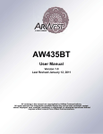
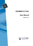
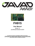
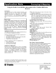
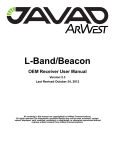
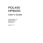
External Radio & APS-3 User Guide Revision 1.01 Radio Configuration Manual © 2008 ALTUS Positioning Systems Inc. All rights reserved. ALTUS, the ALTUS logo, and APS-‐3 are trademarks of ALTUS Positioning Systems Inc. registered in the U.S. and other countries. No part of this document may be copied, used or reproduced without the prior written permission of ALTUS Positioning Systems. No part of this manual may be reproduced or transmitted in any form or by any means, electronic or mechanical, including photocopying and recording, for any purpose without the express written permission of Altus Positioning Systems Inc. Mention of third-‐party products in this document is for informational purposes only and does not constitute an endorsement or a recommendation. ALTUS Positioning Systems assumes no responsibility with regard to the performance or use of the APS-‐3 due to GPS characteristics, USA Department of Defense operations control, atmospheric effects, multipath and RF interference. All understandings, agreements, or warranties take place directly between the seller and the prospective users. Every effort has been made to ensure that the information in this manual is accurate. ALTUS is not responsible for printing or clerical errors. All specifications are typical and subject to change without prior notice. Table of Contents 1 Introduction ..................................................................................................... 5 1.1 Scope ..................................................................................................................................5 1.2 Revision History................................................................................................................5 1.3 Customer Service and Support .......................................................................................5 1.4 Required Equipment ........................................................................................................5 1.4.1 Ports ....................................................................................................................6 1.4.2 APS-3 Power Input .............................................................................................6 2 AW435 .............................................................................................................. 7 2.1 AW435 AWLaunch Configuration .................................................................................7 2.1.1 Configuration to Transmit...................................................................................7 2.1.2 Configuration to Receive ..................................................................................12 2.1.3 Aw435 Firmware Upgrade................................................................................17 2.1.4 AW435 Repeater...............................................................................................19 2.2 AW435 SurvCE Configuration .....................................................................................24 2.2.1 Configuration to Transmit.................................................................................24 2.2.2 Configuration to Receive ..................................................................................29 2.3 APS-3 SurvCE Configuration For AW435 ..................................................................33 2.3.1 Configuration to Receive ..................................................................................33 3 Pacific Crest PDL .......................................................................................... 36 3.1 PDLCONF Configuration..............................................................................................36 3.1.1 Configuration to Transmit/Receive...................................................................36 3.1.2 PDL Firmware Upgrade....................................................................................42 3.1.3 Pacific Crest PDL Repeater ..............................................................................46 3.2 PDL SurvCE Configuration ..........................................................................................52 3.2.1 Configuration to Transmit.................................................................................52 3.2.2 Configuration to Receive ..................................................................................56 3.3 APS-3 SurvCE Configuration For PDL .......................................................................59 3.3.1 Configuration to Transmit.................................................................................59 3.3.2 Configuration to Receive ..................................................................................61 4 Satel Radio ..................................................................................................... 64 4.1 Satelline SaTerm Configuration ...................................................................................64 4.1.1 Configuration to Transmit/Receive...................................................................64 4.1.2 Satel Firmware Upgrade ...................................................................................77 4.1.3 Satel Repeater ...................................................................................................77 4.2 Satel SurvCE Configuration..........................................................................................77 4.2.1 Configuration to Transmit.................................................................................77 4.2.2 Configuration to Receive ..................................................................................77 4.3 APS-3 SurvCE Configuration For Satel.......................................................................77 4.3.1 Configuration to Transmit.................................................................................77 4.3.2 Configuration to Receive ..................................................................................77 5 Intuicom RTK Bridge ................................................................................... 78 5.1 Vendor Configuration ....................................................................................................78 5.1.1 Configuration to Transmit.................................................................................78 5.1.2 5.1.3 Configuration to Receive ..................................................................................78 Intuicom Firmware Upgrade .............................................................................78 5.2 Intuicom SurvCE Configuration...................................................................................78 5.2.1 Configuration to Transmit.................................................................................78 5.2.2 Configuration to Receive ..................................................................................78 5.3 APS-3 SurvCE Configuration For Intuicom ...............................................................78 5.3.1 Configuration to Transmit.................................................................................78 5.3.2 Configuration to Receive ..................................................................................78 6 Trimtalk Radio .............................................................................................. 79 6.1 Vendor Configuration ....................................................................................................79 6.1.1 Configuration to Transmit.................................................................................79 6.1.2 Configuration to Receive ..................................................................................79 6.1.3 Trimtalk Firmware Upgrade .............................................................................79 6.2 Trimtalk SurvCE Configuration...................................................................................79 6.2.1 Configuration to Transmit.................................................................................79 6.2.2 Configuration to Receive ..................................................................................79 6.3 APS-3 SurvCE Configuration For Trimtalk ...............................................................79 6.3.1 Configuration to Transmit.................................................................................79 6.3.2 Configuration to Receive ..................................................................................79 7 Appendix A .................................................................................................... 80 1 Introduction 1.1 Scope The purpose of this document is to provide step-‐by-‐step procedures for configuration and upgrading specific UHF radios for use with an APS-‐3. The model name of the external UHF radios used in this document are; AW400Tx, AW435, and Pacific Crest PDL. These radios will be configured using the vendor supplied software and with SurvCE. 1.2 Revision History Rev 1.00 (March 2009) Rev 1.01 (June 2009) 1.3 Initial Release Subsequent Release Customer Service and Support For any problems or questions, contact ALTUS Positioning Systems support. [email protected] http://www.altus-ps.com/support or write to ALTUS Positioning Systems 20725 Western Avenue, Suite 100 Torrance, CA 90501 (310) 541-‐8139 office (310) 541-‐8257 fax 1.4 • • • • • • • • • Required Equipment APS-‐3 with fully charged batteries or 12 VDC/2 A power supply + Altus External Power Cable, P/N 10031 Altus Controller Cable P/N 10029 Data Collector (Allegro CX, Allegro MX, Archer, Surveyor+) PC with Windows 2000, Windows XP, or Windows Vista Operating System AWLaunch radio configuration program (from Altus) v1R22 or higher AW400Tx firmware Flash file rev xx(from Altus) AW435 External Radio & firmware rev.xx Pacific Crest PDL External Radio & PDLCONF software 12 Volts – 35 Ampere-‐Hour Capacity @ 20-‐Hour Rate Battery Contact Carlson Software for SurvCE warranty and Juniper Systems for Allegro CX/MX & Archer warranty. 1.4.1 Ports Data (8-pin LEMO) Serial 2 Power (4-pin LEMO) External Figure 1: Ports Description Control (5-pin LEMO) Serial 1 Table 1: Lemo Cable Description LEMO Description What to use it for 8pin Data External Radio 5pin Control Controller or Computer 4pin Power External Power 1.4.2 APS-3 Power Input The external power input is via the 4-‐pin Lemo connector. The specifications are: Power Consumption: 3.6W Typical External Power: +9VDC to +15VDC Current: 300mA @ 12V DC Nominal Table 2: Power Cable Description Wire Color Function RED Power (+) BLACK Ground (-) GREEN Reserved WHITE Reserved 2 AW435 2.1 AW435 AWLaunch Configuration 2.1.1 Configuration to Transmit 2.1.1.1 Power the AW435 external radio. 2.1.1.2 Connect CM 10001 cable from the radio to the PC. 2.1.1.3 Start the AWLaunch program. Figure 2: AWLaunch Startup 2.1.1.4 menu. If not already selected, choose ArWest under the Device Interface pull down 2.1.1.5 Click the Preferences tab, and select the Com Port of the computer the AW435 is connected to, and select 115200 for the Baud Rate. Figure 3: Preferences 2.1.1.6 Click the Configuration communication with the AW435. tab, and then select Identify Figure 4: Identify Progress Bar to initiate 2.1.1.7 A successful connection will display fields (if applicable) for the Unit Type, Unit Name, Owner, Call Sign, Serial Number, Firmware Version, Bootloader Version, and Hardware Version. Figure 5: Identification menu 2.1.1.8 Click on the Wireless Interface, and select the appropriate radio settings to transmit to the APS-3; Protocol/Base Simplex Transmitter, RF Channel/Manual Frequency Channel, Modulation/ DQPSK 19.2 kbps, RF Power/ 320 mW – 35 W, Misc/ Scrambling disabled & FEC enabled. Figure 6: Wireless Interface 2.1.1.9 Click on the Serial Interface tab, and ensure the Serial connection is set as shown below. Figure 7: Serial Interface 2.1.1.10 below. Click on the Modem tab, and ensure all settings are disabled as shown Figure 8: Modem 2.1.1.11 below. Click on the Dealer Configuration, and ensure the options are set as shown Figure 9: Dealer Configuration 2.1.1.12 Set the Channel, frequency, RF Power and Channel spacing in this menu. Changes to these settings must match between the base and the rover. Click the Download button to store the new settings into the radio. Figure 10: Programming Progress Bar 2.1.1.13 Configuring the AW435 radio is complete, select Close to disconnect the AW435. 2.1.2 Configuration to Receive The AW435 external radio can be configured to receive by following the steps described below. 2.1.2.1 Power the AW435 external radio. 2.1.2.2 Connect CM 10001 cable from the radio to the PC. 2.1.2.3 Start the AWLaunch program. Figure 11: AWLaunch Startup Page 2.1.2.4 menu. If not already selected, choose ArWest under the Device Interface pull down 2.1.2.5 Click the Preferences tab, and select the Com Port of the computer the AW435 is connected to, and select 115200 for the Baud Rate. Figure 12: Preferences 2.1.2.6 Click the Configuration communication with the AW435. tab, and then select Identify Figure 13: Identification Progress Bar to initiate 2.1.2.7 A successful connection will display fields (if applicable) for the Unit Type, Unit Name, Owner, Call Sign, Serial Number, Firmware Version, Bootloader Version, and Hardware Version. Figure 14: Identification 2.1.2.8 Click on the Wireless Interface, and select the appropriate radio settings to receive; Protocol/Base Simplex Receiver, RF Channel/Manual Frequency Channel, Modulation/ DQPSK 19.2 kbps, RF Power/Disabled, Misc/ Scrambling disabled & FEC enabled. Figure 15: Wireless Interface 2.1.2.9 Click on the Serial Interface tab, and ensure the Serial connection is set as shown below. Figure 16: Serial Interface 2.1.2.10 below. Click on the Modem tab, and ensure all settings are disabled as shown Figure 17: Modem 2.1.2.11 below. Click on the Dealer Configuration, and ensure the options are set as shown Figure 18: Dealer Configuration 2.1.2.12 Set the Channel, frequency, RF Power and Channel spacing in this menu. Changes to these settings must match between the base and the rover. Click the Download button to store the new settings into the radio. Figure 19: Programming Progress Bar 2.1.2.13 Configuring the AW435 radio is complete, select Close to disconnect the AW435. 2.1.3 Aw435 Firmware Upgrade 2.1.3.1 Click the Utilities tab along the left edge of the GUI once the Identify process is complete. 2.1.3.2 Click the Browse button to the right of the GUI. Figure 20: Download Firmware 2.1.3.3 Browse to the location where the AW435/AW400TX firmware file is saved, choose the appropriate file, and click Open. Figure 21: Firmware File Selection 2.1.3.4 Click the Download button, which will change to a Stop button, and the download process will begin. Figure 22: Downloading Firmware 2.1.3.5 Once the download is complete, a dialog indicating a successful operation will be displayed, then click OK to close dialog. Figure 23: Successful Firmware Upgrade 2.1.3.6 If there are no other changes required, click the Close button to disconnect from the AW435. 2.1.4 AW435 Repeater 2.1.4.1 Power the AW435 external radio. 2.1.4.2 Connect CM 10001 cable from the radio to the PC. 2.1.4.3 Start the AWLaunch program. Figure 24: AWLaunch Startup 2.1.4.4 menu. If not already selected, choose ArWest under the Device Interface pull down 2.1.4.5 Click the Preferences tab, and select the Com Port of the computer the AW435 is connected to, and select 115200 for the Baud Rate. Figure 25: Preferences 2.1.4.6 Click the Configuration communication with the AW435. tab, and then select Identify to initiate Figure 26: Identify Progress Bar 2.1.4.7 A successful connection will display fields (if applicable) for the Unit Type, Unit Name, Owner, Call Sign, Serial Number, Firmware Version, Bootloader Version, and Hardware Version. Figure 27: Identification menu 2.1.4.8 Click on the Wireless Interface, and select the appropriate radio settings to transmit to the APS-3; Protocol/Remote Repeater, RF Channel/Manual Frequency Channel, Modulation/ DQPSK 19.2 kbps, RF Power/ 320 mW – 35 W, Misc/ Scrambling disabled & FEC enabled. Figure 28: Wireless Interface 2.1.4.9 Click on the Serial Interface tab, and ensure the Serial connection is set as shown below. Figure 29: Serial Interface 2.1.4.10 below. Click on the Modem tab, and ensure all settings are disabled as shown Figure 30: Modem 2.1.4.11 below. Click on the Dealer Configuration, and ensure the options are set as shown Figure 31: Dealer Configuration 2.1.4.12 Set the Channel, frequency, RF Power and Channel spacing in this menu. Changes to these settings must match between the base and the rover. Click the Download button to store the new settings into the radio. Figure 32: Programming Progress Bar 2.1.4.13 Configuring the AW435 radio is complete, select Close to disconnect the AW435. 2.2 AW435 SurvCE Configuration 2.2.1 Configuration to Transmit An external radio or external modem can be used to output corrections to the APS-‐3. This is done by configure an external radio/modem as illustrated below. 2.2.1.1 Start SurvCE Select Equip tab Select GPS Base Select RTK tab 2.2.1.2 In the RTK tab, select ARWest from the Device menu. Figure 33: RTK Tab 2.2.1.3 In the Baud menu select 115200. Figure 34: Baud Rate Selection 2.2.1.4 Select the message type of the corrections desired. Figure 35: Message Type Menu 2.2.1.5 Select the Configure button to continue APS-3/external base configuration. Figure 36: Configure External Base 2.2.1.6 Select Protocol/Simplex. Figure 37: External Radio Protocol Menu 2.2.1.7 Select a Power value between 25 db (~320 mW) and 45 db (35 Watts). Figure 38: External Radio Power Menu 2.2.1.8 Select a desired channel, and then select the green check mark box to send the settings to the radio. Figure 39: External Radio Channel Selection 2.2.1.9 A Device Configured message confirms configuration was sent to the radio. Figure 40: Device Configured 2.2.1.10 Continue Base setup by selecting the green check mark box. Then, SurvCE will prompt for base position input. Follow the procedures found in the APS-3 User manual to setup the GPS Base Position. Figure 41: GPS Base Settings 2.2.2 Configuration to Receive 2.2.2.1 Start SurvCE Select Equip tab Select GPS Rover Select RTK tab 2.2.2.2 In the RTK tab, select ArWest from the Device menu. Figure 42: Device Selection 2.2.2.3 In the Baud menu select 115200. Figure 43: Baud Rate Selection 2.2.2.4 Select the message type of the corrections desired. Figure 44: Message Type Menu 2.2.2.5 Select the Configure button to continue configuration. Figure 45: Configure External Base 2.2.2.6 Select Protocol/Simplex. Figure 46: External Radio Protocol Menu 2.2.2.7 The previously selected radio Power and Channel number with frequency is displayed. Select desired Power (Power has no effect on rover), and Channel number, then select the green check mark box to send the settings to the radio. Figure 47: External Radio Power Menu 2.2.2.8 A Device Configured message confirms configuration was sent to the radio. 2.2.2.9 Continue setup by selecting the green check mark box. Figure 48: GPS Rover Settings 2.3 APS-3 SurvCE Configuration For AW435 2.3.1 Configuration to Receive 2.3.1.1 Start SurvCE Select Equip tab Select GPS Rover Select RTK tab 2.3.1.2 In the RTK tab select Internal Radio from the Device drop down menu. Figure 49: Internal Radio Selection 2.3.1.3 Select Message Type from the drop down menu - CMR / RTCM V2.3 / RTCM V3.0. 2.3.1.4 Then click the Configure button. Figure 50: Configure Internal Radio 2.3.1.5 The previously selected radio Power and Channel number with frequency is displayed. Select desired Power (Power has no effect on rover), and Channel number, then select the green check mark box to send the settings to the radio. Figure 51: Current Channel Setting 2.3.1.6 Click the green check mark to finalize the Rover settings to the receiver. The display will show “Device Configured Successfully,” AND the screen will return to the Equip menu as shown below. Figure 52: Display after Radio Configuration 2.3.1.7 The Rover configuration is complete. 3 Pacific Crest PDL 3.1 PDLCONF Configuration 3.1.1 Configuration to Transmit/Receive 3.1.1.1 Select the PDL menu button in the top left corner. 3.1.1.2 Select the Set Capture Method option, and choose Power On Capture or Soft Break. Figure 53: Capture Method Options 3.1.1.3 Click the PDL menu button again, and choose Select Serial Port… Figure 54: PDLConf Menu Options 3.1.1.4 Wait for a moment for the Serial Port menu to display, and then select the computer port where the Pacific Crest PDL radio is connected. Figure 55: Serial Port Selection 3.1.1.5 Select Load, and then power on the radio. Figure 56: PDLConf Startup Screen 3.1.1.6 A progress bar will be displayed when the settings are being read from the modem. Figure 57: Loading Modem Settings 3.1.1.7 Once the settings are obtained from the radio the model information will be displayed. Figure 58: PDL Base Identification 3.1.1.8 Select the Frequencies tab, and enter in transmitting and receiving frequencies in MHz. 3.1.1.9 Take note of the channel numbers associated with each frequency, for base/rover radio matching. Figure 59: PDL Frequencies The compatibility of the APS-‐3 with the PDL is based on the model and firmware at the time of testing. Any change by Pacific Crest may affect operations. 3.1.1.10 Select the Radio Link tab. Channel Select Link Rate Modulation Type Digisquelch Transmit Retries TX ACK Timeout Forward Error Correction Scrambling CSMA Monitor Local Address Remote Address Manual + Channel 9600 GMSK High 3 0.1 Enabled Disabled Enabled 0 255 Figure 60: PDL Radio Link 3.1.1.11 Select the Serial Interface tab. 3.1.1.12 Port Baud Rate Parity Modem Enabled Soft Break Enabled Data Security 38400 None Enabled Enabled 00000000 3.1.1.13 Protocol Mode EOT Count Break to Command Repeater Digipeater Delay Transparent w/EOT Timeout 5 Disabled Disabled 0.00 Figure 61: PDL Serial Interface See the Pacific Crest website for information and tools required to configure the Pac Crest PDL radio modem. When SurvCE is used to configure the Pacific Crest PDL, parameters for Modulation, Link Rate and Serial Interface are automatically set. 3.1.2 PDL Firmware Upgrade 3.1.2.1 Select the PDL menu button in the top left corner. 3.1.2.2 Then select Upgrade modem firmware. Figure 62: PDLConf Menu selection 3.1.2.3 Path to the saved Pacific Crest firmware files saved on the computer (.fw) and select Open. Figure 63: Modem Firmware Selection 3.1.2.4 Select Yes on the confirmation menu. Figure 64: Firmware Location Confirmation 3.1.2.5 A progress bar will display progression of the firmware being downloaded to the modem. Do not disconnect modem at this time. Figure 65: Downloading Firmware to the Modem 3.1.2.6 Once the downloading is complete a confirmation will display the firmware revision that has been written to the modem. Select Ok. Figure 66: Firmware Upgrade Confirmation 3.1.2.7 Power-cycle the radio OFF and ON, then reload the radio and verify the firmware upgrade in the model information under the Identification tab. Figure 67: Firmware Upgrade – Cycle Power 3.1.2.8 The radio firmware has successfully been upgraded. Figure 68: Firmware Upgrade Complete 3.1.3 Pacific Crest PDL Repeater 3.1.3.1 Select the PDL menu button in the top left corner. 3.1.3.2 Select the Set Capture Method option, and choose Power On Capture or Soft Break. Figure 69: Capture Method Options 3.1.3.3 Click the PDL menu button again, and choose Select Serial Port… Figure 70: Opening a COM Port 3.1.3.4 Wait for a moment for the Serial Port menu to display, and then select the computer port where the Pacific Crest PDL radio is connected. Figure 71: Serial Port Selection 3.1.3.5 Select Load, and then power on the radio. Figure 72: PDLConf Startup Screen 3.1.3.6 A progress bar will be displayed when the settings are being read from the modem. Figure 73: Loading Modem Settings 3.1.3.7 Once the settings are obtained from the radio the model information will be displayed. Figure 74: PDL Base Identification 3.1.3.8 Select the Frequencies tab, and enter in transmitting and receiving frequencies in MHz. 3.1.3.9 Take note of the channel numbers associated with each frequency, for base/rover radio matching. Figure 75: PDL Frequencies The compatibility of the APS-‐3 with the PDL is based on the model and firmware at the time of testing. Any change by Pacific Crest may affect operations. 3.1.3.10 Select the Radio Link tab. Channel Select Link Rate Modulation Type Digisquelch Transmit Retries TX ACK Timeout Forward Error Correction Scrambling CSMA Monitor Local Address Remote Address Manual + Channel 9600 GMSK High 3 0.1 Enabled Disabled Enabled 0 255 Figure 76: PDL Radio Link 3.1.3.11 Select the Serial Interface tab. 3.1.3.12 Port Baud Rate Parity Modem Enabled Soft Break Enabled Data Security 38400 None Enabled Enabled 00000000 3.1.3.13 Protocol Mode EOT Count Break to Command Repeater Digipeater Delay Transparent w/EOT Timeout 5 Disabled Enabled 0.00 Figure 77: PDL Serial Interface 3.1.3.14 Once all the settings have been set, select the Program button. Then select Yes on the confirmation screen. Figure 78: Programming Confirmation The new settings will be displayed when the programming is complete. Click Close when 3.2 PDL SurvCE Configuration 3.2.1 Configuration to Transmit 3.2.1.1 Select SurvCE Equip tab GPS Base RTK tab 3.2.1.2 In the RTK tab, select Device = Pacific Crest PDL. Figure 79: External Radio Device Selection 3.2.1.3 Select the desired Baud Rate for the Pacific Crest PDL. (Note: The highest baud rate for the Pacific Crest PDL is 38400). Figure 80: Baud Rate Selection 3.2.1.4 Select the message type of the corrections desired. Figure 81: Message Type Selection 3.2.1.5 Select the Configure button to continue configuring the external Pacific Crest PDL radio. Figure 82: Pac. Crest PDL Configuration 3.2.1.6 The current configuration of the radio is shown. Select a desired channel to transmit on and select Squelch = Low. Then select the green check mark box to continue with the base setup. Figure 83: External Pac Crest Radio 3.2.1.7 A Device Configured message confirms configuration was sent to the radio. Figure 84: Device Configured 3.2.1.8 Continue Base setup by selecting the green check mark box. Then, SurvCE will prompt for base position input. Follow the procedures found in the APS-3 User Manual to setup the GPS Base Position. Figure 85: Complete Base setup 3.2.2 Configuration to Receive 3.2.2.1 Start SurvCE Select Equip tab Select GPS Rover Select RTK tab 3.2.2.2 In the RTK tab, select Pacific Crest PDL from the Device menu. Figure 86: RTK Device Selection 3.2.2.3 In the Baud menu select 38400. Figure 87: Baud Rate Selection 3.2.2.4 Select the message type of the corrections desired. Figure 88: Message Type Selection 3.2.2.5 Select the Configure button to continue configuration. Figure 89: Pacific Crest PDL Setup 3.2.2.6 The previously configured radio Channel and Squelch level will be displayed. Select a desired channel number and squelch level, and then select the green check mark box to send the settings to the radio. Figure 90: Pacific Crest Radio Settings 3.2.2.7 A Device Configured message confirms configuration was sent to the radio. 3.2.2.8 Continue setup by selecting the green check mark box. Figure 91: Pacific Crest PDL Setup Complete 3.3 APS-3 SurvCE Configuration For PDL 3.3.1 Configuration to Transmit 3.3.1.1 Select SurvCE Equip tab GPS Base RTK tab 3.3.1.2 In the RTK tab, select Device = Internal Radio. Figure 92: RTK Device Selection 3.3.1.3 Select the message type of the corrections desired. Figure 93: Message Type Selection 3.3.1.4 Select the Configure button. The current configuration of the radio is shown. Select a Protocol/PDL w/EOT, Power/User Specified, Channel/User. Then select the green check mark box to continue with the base setup. Figure 94: Radio Settings 3.3.1.5 A Device Configured message confirms configuration was sent to the radio. 3.3.1.6 Continue Base setup by selecting the green check mark box. Then, SurvCE will prompt for base position input. Follow the procedures found in the APS-3 User manual to setup the GPS Base Position. Figure 95: Radio Configured 3.3.2 Configuration to Receive 3.3.2.1 Start SurvCE Select Equip tab Select GPS Rover Select RTK tab 3.3.2.2 In the RTK tab, select Device = Internal Radio. Figure 96: Internal Radio w/ Base Ext. Radio 3.3.2.3 In the RTK tab, select Message Type to match base message type. Then select Configure. Figure 97: Message Type Menu 3.3.2.4 The previously setup configuration will be recalled. Figure 98: Configuration Settings 3.3.2.5 In the Configuration Menu, select Protocol = PDL w/EOT, Power = 1 Watt, Channel = match frequency to base frequency. An example configuration for a rover receiving from an external Pacific Crest Radio is below. 3.3.2.6 Select the green check mark box to send the configuration to the radio. Figure 99: Internal Radio w/ PDL Settings 3.3.2.7 After the Device Configured message, select the green check mark box to finalize the GPS Rover (receiving from a Pacific Crest PDL) configuration. The screen will return to the main Equip menu. Figure 100: GPS Rover Configuration 4 Satel Radio This configuration is under development 4.1 Satelline SaTerm Configuration 4.1.1 Configuration to Transmit/Receive 4.1.1.1 Start up SATELLINE SaTerm 4.0.4 4.1.1.2 Select the New Terminal button Figure 101: Satelline SaTerm Startup Page below the mode menu. 4.1.1.3 Select the Port number where the radio is connected. 4.1.1.4 Select 9600 for the Baud rate, and leave other fields unchanged except for user specific requirements. Then select OK. Figure 102: Serial Port Setup 4.1.1.5 Put the radio into programming mode by flipping the Programming Mode Switch. 4.1.1.6 mode. The Current Settings will be displayed in the main menu of programming 4.1.1.7 Enter in selection 1 to adjust the Radio Frequency. Figure 103: Current Setting/ Main Menu 4.1.1.8 MHz. In the Radio Frequency Setup menu the allowable limits will be displayed in Figure 104: Radio Frequency Band/Channel 4.1.1.9 Enter a new frequency in MHz. 4.1.1.10 Enter ESC to return to the main menu. Figure 105: Radio Frequency Setup 4.1.1.11 Notice the radio frequency will now display the frequency entered in the previous step. Figure 106: Current Settings/Main Menu 4.1.1.12 4.1.1.13 Enter selection 2 to adjust the Radio Setting. In the Radio Setup menu, select option 1 to adjust the transmitting power. Figure 107: Radio Setup Menu 4.1.1.14 In the Transmitter Power Setup menu, select option 1-5 for the required power level. Notice transmission power does not apply to a receiver. Figure 108: Transmitter Power Setup Menu 4.1.1.15 In the Radio Setup menu, select option 8 to change the Radio Compatibility. Figure 109: Radio Setup Menu 4.1.1.16 In the Radio Compatibility Mode menu, select “Option 2” when communicating APS-3 Internal Radio to Satel Radio (or vice versa). Select “Satel 3AS” when communicating Satel Radio to Satel Radio. Do not select “Option 1.” Figure 110: Radio Compatibility Menu 4.1.1.17 Enter ESC once Radio Setup is complete. Figure 111: Radio Setup w/ Current Radio settings 4.1.1.18 Entering ESC will return display to the main menu, and the new TX Power level and Compatibility Settings are displayed. Figure 112: Current Settings/Main Menu 4.1.1.19 4.1.1.20 Speed. Select option 4 to adjust Serial Port 1 Settings. In the Serial Port 1 Settings menu, select option 2 to change the Data Figure 113: Serial Port 1 Settings Menu 4.1.1.21 In the Data Speed menu, select 38400 bit/s. Figure 114: Serial Port 1 Data Speed Menu 4.1.1.22 The new data speed will be displayed in the Serial Port 1 Settings Menu. Enter ESC to return to the main menu. Figure 115: Serial Port 1 Current Settings 4.1.1.23 Notice the Serial Port 1 settings have been adjusted in the main menu to illustrate the current settings. Figure 116: Current Settings/Main Menu 4.1.1.24 Enter option 7 to adjust Additional Setup. 4.1.1.25 In the Additional Setup menu, enter in option 1 to toggle the Error Corrections ON Figure 117: Additional Setup Menu 4.1.1.26 Notice the Error Corrections option has been toggled ON. 4.1.1.27 Enter ESC to return to the main menu. Figure 118: Additional Setup Current Settings 4.1.1.28 menu. Notice the Error Corrections has been adjusted in the Additional setup Figure 119: Current Settings/Main Menu 4.1.1.29 Enter option E to save settings and exit programming. 4.1.1.30 Turn off programming mode by flipping the Programming Mode Switch to the initial position. Figure 120: Exit and Save Settings 4.1.1.31 For instructional purposes, switch back to programming mode. Then select option A to Restore Factory (Satel) Settings. Figure 121: Current Settings/Main Menu 4.1.1.32 Choose Y to restore factory settings. Figure 122: Restore Factory Settings Selection 4.1.1.33 Notice the Factory Settings have been configured. Exit programming mode by either saving and exiting or by quitting without saving. Figure 123: Factory Settings/Main Menu 4.1.2 Satel Firmware Upgrade 4.1.3 Satel Repeater 4.2 Satel SurvCE Configuration 4.2.1 Configuration to Transmit 4.2.2 Configuration to Receive 4.3 APS-3 SurvCE Configuration For Satel This configuration is under development – new SurvCE release 4.3.1 Configuration to Transmit 4.3.2 Configuration to Receive 5 Intuicom RTK Bridge This configuration is under development 5.1 Vendor Configuration 5.1.1 Configuration to Transmit 5.1.2 Configuration to Receive 5.1.3 Intuicom Firmware Upgrade 5.2 Intuicom SurvCE Configuration 5.2.1 Configuration to Transmit 5.2.2 Configuration to Receive 5.3 APS-3 SurvCE Configuration For Intuicom This configuration is under development – new SurvCE release 5.3.1 Configuration to Transmit 5.3.2 Configuration to Receive 6 Trimtalk Radio This configuration is under development 6.1 Vendor Configuration 6.1.1 Configuration to Transmit 6.1.2 Configuration to Receive 6.1.3 Trimtalk Firmware Upgrade 6.2 Trimtalk SurvCE Configuration 6.2.1 Configuration to Transmit 6.2.2 Configuration to Receive 6.3 APS-3 SurvCE Configuration For Trimtalk This configuration is under development – new SurvCE release 6.3.1 Configuration to Transmit 6.3.2 Configuration to Receive 7 Appendix A Figure 124: APS-3 Radio Settings