1
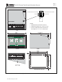
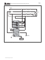
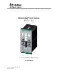
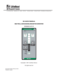
3714 Kinnear Place Saskatoon, Saskatchewan Canada S7P 0A6 Ph: (306) 373-5505 Fx: (306) 374-2245 www.startco.ca SE-502 MANUAL GROUND-FAULT GROUND-CONTINUITY DETECTOR April 25, 2012 REVISION 0 Copyright © 2012 by Littelfuse Startco All rights reserved. Publication: SE-502-M Document: S95-C502-00000 Printed in Canada. SE-502 Ground-Fault Ground-Continuity Detector This page left intentionally blank. Pub. SE-502-M, April 25, 2012. Page i Rev. 0 SE-502 Ground-Fault Ground-Continuity Detector PREFACE Current flowing to ground has only two paths—it can flow to ground through a ground fault, and it can flow to ground through distributed capacitance. Current flowing to ground through distributed capacitance can cause sympathetic tripping during a ground fault and its unbalance can cause tripping during normal operation. These trips are not to be confused with false trips that occur when poorly designed ground-faultdetection systems respond to anything other than zero-sequence current at the fundamental frequency. All of these trips are nuisance trips. If nuisance trips are frequent enough to interfere with production, there is a danger that the protection will be defeated. A sympathetic ground-fault trip is a trip that occurs on an unfaulted portion of a system when a ground fault occurs elsewhere in the system. Sympathetic tripping can occur if capacitive current flowing to a ground-fault from an unfaulted portion of the system is larger than the ground-fault trip level. Consequently, coordination using conventional ground-fault relays and zero-sequence-current detectors requires the groundfault trip level to be larger than the charging current of the largest protected portion of the system. Since this trip level is usually larger than the unbalanced capacitive current flowing to ground due to unbalanced voltage and/or capacitance to ground, a coordinated, well-designed, ground-fault-protection system will not have nuisance trips. In small systems or systems with one ground-fault relay, sympathetic tripping is not a concern and nuisance tripping can be avoided if the ground-fault trip level is larger than the unbalanced capacitive current flowing to ground. Unfortunately, this level is usually above the trip levels required for single-phase Class-A GFCI’s and personnel protection must be achieved by other means. In distribution and utilization systems, protection is achieved by controlling touch and step potentials and by limiting the voltage to which exposed metal parts can rise during a ground fault—no attempt is made to trip at the GFCI levels mandated for small singlephase loads. In spite of the fact that GFCI levels were never intended for three-phase systems, attempts are often made to achieve these trip levels on equipment such as submersible pumps. A special problem exists with respect to portable generators. Most electrical codes require portable generators to be grounded with ground rods or electrodes; however, location and conditions can make this difficult to achieve. This problem has been recognized by Ontario Hydro—Electrical Inspection, Metro Territory. On September 28, 1998, Ontario Hydro issued guidelines to Inspectors and the entertainment industry to assist them to achieve safe electrical installations. These guidelines allow a ground (other than an approved electrode) to be used if it is verified with a ground proving device. Also, in 1997 the Construction Safety Association of Ontario (CSAO) published a report titled The Use of Ground Fault Circuit Interrupters on Portable Generators. This report outlines conditions under which personnel protection is not achieved with GFCI’s. The SE-502 Ground-Fault Ground-Continuity Detector provides a solution to the problem of personnel protection for portable generators. It also has application in utilization systems requiring a lockout that will not allow a faulted system Pub. SE-502-M, April 25, 2012. Page ii Rev. 0 to be energized. Consider the following: Since capacitance to ground causes nuisance-tripping levels in conventional systems to be larger than Class-A GFCI trip levels, a technique that ignores capacitive current to ground is required if Class-A GFCI trip levels are to be achieved without nuisance tripping. The SE-502 accomplishes this by using a dc signal to measure resistance to ground of the entire system. The disadvantage of this technique is that it will not detect current through a person contacting a phase conductor with a series capacitor. We are faced with a conundrum—it is impossible to build a protective relay that both ignores and detects capacitive current. Since the probability of contact through a capacitor is much smaller than the probability of direct or resistive contact, the SE-502 reduces risk to personnel by providing protection in the most probable occurrences that could result in electrocution. It is a common misconception that conventional GFCI’s limit ground-fault current to 5 or 30 mA. They do not. Ground-fault current is limited only by the system impedance until the trip occurs. The SE-502 limits ground-fault current to a maximum value of 100 mA. A very positive consequence of the 100-mA limit is that the arc-flash hazard on the first ground fault is eliminated. The SE-502 confirms an acceptable ground so that a ground-fault trip is assured when a ground fault occurs. Ground-fault operation can be easily and safely tested on a de-energized system. The SE-502 resistance grounds the system; ensure local electrical codes permit the use of resistance grounding with line-to-neutral loads. Canadian Electrical Code Section 10-1102 specifically allows, and lists provisions for, lineto-neutral loads on resistance-grounded systems. SE-502 Ground-Fault Ground-Continuity Detector This page left intentionally blank. Pub. SE-502-M, April 25, 2012. Page iii Rev. 0 Page iv Rev. 0 SE-502 Ground-Fault Ground-Continuity Detector TABLE OF CONTENTS PAGE Preface ............................................................................ i 1. General .......................................................................... 1 2. 2.1 2.3 Operation ....................................................................... 1 Configuration-Switch Settings ..................................... 1 2.1.1 Trip Relay Operating Mode ............................ 1 2.1.2 Ground-Continuity Trip .................................. 1 Front-Panel Indication .................................................. 1 2.2.1 Ground Fault .................................................... 1 2.2.2 Ground Continuity........................................... 1 2.2.3 Power ............................................................... 2 2.2.4 Open Neutral.................................................... 2 2.2.5 Diagnostic Error .............................................. 2 Reset .............................................................................. 2 3. Installation ..................................................................... 2 4. Technical Specifications ............................................... 2 5. Warranty........................................................................ 2 2.2 Pub. SE-502-M, April 25, 2012. LIST OF FIGURES 1 2 PAGE SE-502 Outline and Mounting Details ......................... 3 SE-502 Typical Application ......................................... 4 DISCLAIMER Specifications are subject to change without notice. Littelfuse Startco is not liable for contingent or consequential damages, or for expenses sustained as a result of incorrect application, incorrect adjustment, or a malfunction. SE-502 Ground-Fault Ground-Continuity Detector This page intentionally left blank. Pub. SE-502-M, April 25, 2012. Page v Rev. 0 SE-502 Ground-Fault Ground-Continuity Detector Page 1 Rev. 0 1. GENERAL 2. OPERATION The SE-502 is a microprocessor-based, ground-fault and ground-continuity detector that provides Class-A GFCI trip levels and trip times for a three-phase 120/208-V portable generator. All operating conditions are clearly indicated and Form C contacts are provided for the main breaker’s trip circuit. Two Form C contacts are also provided for remote ground-fault and ground-continuity indication. All specifications apply over an industrial temperature range at high humidity, and the SE-502 is designed to meet the IEEE surge-withstand-capability tests (oscillatory and fast transient) for protective relays and relay systems. The SE-502’s ground-fault circuit has an internal neutralgrounding resistor (NGR) that limits ground-fault current to 100 mA. This eliminates the flash hazard, and susceptibility to nuisance tripping is reduced as trip times less than 100 ms are not required to achieve Class-A GFCI performance. The SE-502 impresses a small dc voltage on the neutral of the generator to measure the resistance to ground of the entire system connected to the load side of the generator’s main breaker. If resistance to ground is less than 24 k (5 mA @ 120 V), the SE-502 will trip the main breaker in less than Class-A times and it will not allow the main breaker to close until resistance to ground is greater than 24 k. LED indication and a relay for remote indication of a ground fault are diagnostic tools that allow a ground fault to be easily located on a de-energized system. When a faulted section is disconnected from the system by breakers or by couplers, the SE-502 will indicate that no fault exists and it will allow the main breaker to be set. The SE-502 is designed to be used in a tripping system. If a system remains energized with a ground fault, the SE-502 will reduce NGR current if NGR temperature approaches its thermal limit. The SE-502’s ground-continuity circuit uses a sense lead connected to a probable ground to confirm that the electrode chosen for the system ground is an acceptable ground. Ground-electrode-loop resistance must be less than 25 for the circuit to confirm the ground. LED indication and a relay for remote indication allow probable grounds to be easily tested for acceptability. If the ground-continuity-trip switch is in the ENABLE position, the resistance of the ground-electrode loop will be continuously monitored and it will trip the main breaker if the loop resistance increases above 50 . The SE-502 neutral-continuity circuit uses a sense lead connected to the system neutral to continuously monitor continuity of the neutral circuit. A loss of continuity initiates a trip, which is indicated with an LED. 2.1 CONFIGURATION-SWITCH SETTINGS See Fig. 1. 2.1.1 TRIP RELAY OPERATING MODE Switches 1 and 2 are used to set the operating mode of the trip relay. In the non-fail-safe mode, the trip relay is energized when a trip occurs. In the fail-safe mode, the trip relay is energized when the circuits are not tripped. Nonfail-safe operation requires both switches to be in the nonfail-safe position. Switches 1 and 2 do not affect operation of the groundfault and ground-continuity annunciation relays. Pub. SE-502-M, April 25, 2012. 2.1.2 GROUND-CONTINUITY TRIP Switch 3 is used to ENABLE or DISABLE groundcontinuity trip. In the DISABLE position, a loss of ground continuity will not cause a trip. In the ENABLE position, ground-continuity loop resistance must increase above 50 for 1 s to cause a ground-continuity trip. A groundcontinuity trip will not reset unless loop resistance is less than 25 . In both switch positions, ground continuity is indicated and the remote-indication relay is energized when ground-electrode-loop resistance is less than 25 . 2.2 FRONT-PANEL INDICATION 2.2.1 GROUND FAULT The red LED labeled TRIP indicates a ground-fault circuit trip. See Section 2.3. The yellow LED labeled PRESENT indicates that a ground fault is present. The ground-fault annunciation relay is not energized. The green LED labeled CLEAR indicates that a ground fault is not present. The ground-fault annunciation relay is energized. 2.2.2 GROUND CONTINUITY The red LED labeled TRIP indicates a ground-continuitycircuit trip. A trip will remain latched until the groundelectrode-loop resistance is less than 25 and a reset is performed. See Section 2.3. The yellow LED labeled NO indicates an unacceptable ground-electrode-loop resistance. The ground-continuity annunciation relay is not energized and a groundcontinuity trip will not reset. The green LED labeled YES indicates an acceptable ground-electrode-loop resistance. The ground-continuity annunciation relay is energized and a ground-continuity trip can be reset. SE-502 Ground-Fault Ground-Continuity Detector 2.2.3 POWER The green LED labeled POWER indicates presence of the supply voltage. 2.2.4 OPEN NEUTRAL The red LED labeled OPEN NEUTRAL indicates an open-neutral trip. An open-neutral trip is caused by a lack of continuity between NEUTRAL SENSE terminal 8 and NEUTRAL terminals 1 and 2. See Fig. 2. Some lamp-ballast-ground tests may cause a nuisance open-neutral trip. 2.2.5 DIAGNOSTIC ERROR The red LED labeled DIAGNOSTIC ERROR indicates a diagnostic-error trip. Press RESET or cycle supply voltage. If problem persists, contact Littelfuse Startco. A flashing LED indicates that the NGR has reached its thermal limit. Clear the ground fault, allow the SE-502 to cool, and press RESET. 2.3 RESET When a trip occurs, the trip remains latched until the RESET switch is pressed, the remote-reset terminals (12 and 13) are shorted, or the supply voltage is cycled. The reset circuit responds only to a momentary closure so that a jammed or shorted switch will not maintain a reset signal. 3. INSTALLATION An SE-502 can be surface or DIN-rail mounted. See Fig. 1. Connect the SE-502 as shown in Fig. 2. Ensure that the generator neutral is not internally grounded. Remove the connection to terminal 18 for dielectric-strength testing—all inputs and outputs have ANSI/IEEE C37.90 surgeprotection circuits that conduct above 300 Vac. 4. TECHNICAL SPECIFICATIONS Supply: 120 Vac (+15%, -30%), 50/60 Hz, 3.5 VA Dimensions: Height .................................... 75 mm (3.0") Width ..................................... 100 mm (4.0") Depth ..................................... 113 mm (4.4") Shipping Weight ........................... 0.68 kg (1.5 lb.) Ground-Fault Circuit: Trip Level .............................. 5 ± 0.9 mA Trip Time .............................. (Class A GFCI - 25 ms) max. 5–15 mA ........................ 250 ms max. 15–100 mA .................... 75 ms max. (average of 10 or more measurements) Pub. SE-502-M, April 25, 2012. Page 2 Rev. 0 NGR ...................................... 1440 Thermally Protected Ground-Continuity Circuit: Continuity Indication ............ < 25 Trip Resistance ..................... > 50 Trip Time .............................. 1 ± 0.1 s Neutral-Sense Circuit: Trip Time .............................. 5 ± 0.1 s Reset ............................................. Front-Panel Switch and Remote N.O. Momentary Contact Output Relays: Contact Rating ..................... 8 A Resistive, 250 Vac/30 Vdc Contact Configuration ......... Form C Trip Relay Operating Mode ................ Fail Safe or Non Fail Safe Annunciation Relays Operating Mode ................ Fail Safe Environment: Operating Temperature ........ -40°C to 70°C Storage Temperature ............ -55°C to 80°C Humidity ............................... 85% Non Condensing Surge Withstand ........................... ANSI/IEEE 37.90.1-1989 (Oscillatory and Fast Transient) 5. WARRANTY The SE-502 Ground-Fault Ground-Continuity Detector is warranted to be free from defects in material and workmanship for a period of five years from the date of purchase. Littelfuse Startco will (at Littelfuse Startco’s option) repair, replace, or refund the original purchase price of an SE-502 that is determined by Littelfuse Startco to be defective if it is returned to the factory, freight prepaid, within the warranty period. This warranty does not apply to repairs required as a result of misuse, negligence, an accident, improper installation, tampering, or insufficient care. Littelfuse Startco does not warrant products repaired or modified by non-Littelfuse Startco personnel. Page 3 Rev. 0 SE-502 Ground-Fault Ground-Continuity Detector GROUND-CONTINUITY-TRIP ENABLE FAIL-SAFE 3 2 1 GROUND-CONTINUITY-TRIP DISABLE NON-FAIL SAFE NOTES: 1. DIMENSIONS IN MILLIMETRES (INCHES). N 1 NEUTRAL CONTINUITY RESET SENSE SENSE G 2 3 4 5 6 7 8 9 10 11 2. MOUNTING SCREWS: M4 x 13 OR 8-32 x 0.50. 12 13 14 15 3. OVERALL DIMENSION WHEN MOUNTED ON DIN EN50022 35 mm x 7.5 mm TOP-HAT RAIL. TOP 99.80 (3.93) 75.0 (2.95) 113.0 (NOTE 3) (4.45) FRONT SIDE 7.4 61.2 (2.41) 75.0 (2.95) 16 17 18 19 20 21 22 23 24 25 26 27 28 29 30 GROUND GROUND L2 FAULT CONTINUITY TRIP / S P L1 N G (0.29) 99.80 (3.93) 85.0 (3.35) MOUNTING DETAIL FIGURE 1. SE-502 Outline and Mounting Details. Pub. SE-502-M, April 25, 2012. 6.9 (0.27) BOTTOM SE-502 Ground-Fault Ground-Continuity Detector Page 4 Rev. 0 GENERATOR 120/208 V CABLE 120-V LOADS N 16 L1 L2/N 21 17 TRIP 20 TRIP 22 GF 23 GF 25 UV G 24 UV ENERGIZED R GF INDICATOR 27 GC 26 G GC 28 GC INDICATOR REMOTE RESET 12 13 1 2 RESET NEUTRAL 8 SENSE GROUND NEUTRAL 5 6 SE-502 18 19 SPG CONTINUITY 10 SENSE GROUND ELECTRODE SENSE LEAD TO ALTERNATE GROUND FIGURE 2. SE-502 Typical Application. Pub. SE-502-M, April 25, 2012.