1
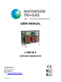
USER MANUAL
LCMS M-4
NITROGEN GENERATOR
MATHESON TRI-GAS
166 Keystone Drive
Montgomeryville, PA 18936
Phone: 215-641-2700
Fax: 215-641-2714
Email: [email protected]
INT-0262-XX rev B
2005 Matheson Tri-Gas
All rights reserved
No part of this publication may be produced and/or publicized by being printed, photocopied, and/or placed on microfilm or in any other manner without the prior written permission of Matheson Tri-Gas.
Matheson Tri-Gas retains the right to make changes in parts at any point without first or directly notifying the customer. The contents of this manual
can also be changed without prior warning.
This manual is valid for the LCMS M-4 nitrogen generator in its standard version. Matheson Tri-Gas can therefore not be held liable for specifications
of the delivered system that may deviate from the standard version.
For information concerning adjustments, maintenance or repairs not contained in this manual, please contact Matheson Tri-Gas.
INT-0262-XX rev B
2 of 23
USER MANUAL ................................................................................................................................................................................ 1
1
INTRODUCTION ...................................................................................................................................................................... 4
1.1
1.2
1.3
1.4
1.5
1.6
1.7
2
General ........................................................................................................................................... 4
Pictograms in this manual .............................................................................................................. 4
Identification and service ............................................................................................................... 5
Certificates ..................................................................................................................................... 5
Intended uses .................................................................................................................................. 5
User instructions............................................................................................................................. 5
Liability .......................................................................................................................................... 5
HEALTH, SAFETY AND ENVIRONMENTAL COMPLIANCE........................................................................................ 6
2.1
2.2
2.3
2.4
2.5
3
General ........................................................................................................................................... 6
Nitrogen and oxygen ...................................................................................................................... 6
Electricity ....................................................................................................................................... 6
Safety precautions .......................................................................................................................... 6
Environmental aspects.................................................................................................................... 7
DESCRIPTION .......................................................................................................................................................................... 8
3.1
3.2
3.3
3.4
3.5
General ........................................................................................................................................... 8
Separation principle........................................................................................................................ 8
Parts................................................................................................................................................ 9
Process Diagram........................................................................................................................... 10
Process Schematic ..................................................................................................................... 11
TECHNICAL SPECIFICATIONS ......................................................................................................................................... 12
4
4.1
4.2
4.3
5
General ......................................................................................................................................... 12
Production capacity ...................................................................................................................... 13
Maintenance items........................................................................................................................ 13
INSTALLATION ..................................................................................................................................................................... 14
5.1
5.2
5.3
5.4
5.5
6
Transport ...................................................................................................................................... 14
Location........................................................................................................................................ 14
Unpack and check equipment....................................................................................................... 14
Connect to application.................................................................................................................. 14
Start up the LCMS M-4 nitrogen generator.................................................................................. 14
OPERATION............................................................................................................................................................................ 15
6.1
6.2
6.3
7
Start LCMS M-4 nitrogen generator ............................................................................................ 15
Stop LCMS M-4 nitrogen generator............................................................................................. 15
Control panel ................................................................................................................................ 16
TROUBLESHOOTING........................................................................................................................................................... 17
7.1
8
Error list........................................................................................................................................ 17
MAINTENANCE ..................................................................................................................................................................... 18
8.1
8.2
8.3
8.4
8.5
9
10
Maintenance schedule .................................................................................................................. 18
Inlet filter element replacement.................................................................................................... 18
Oxygen sensor replacement.......................................................................................................... 18
Oxygen sensor calibration ............................................................................................................ 19
Pressure switch control................................................................................................................. 20
ELECTRICAL SCHEMATIC ................................................................................................................................................ 22
INDEX ................................................................................................................................................................................... 23
INT-0262-XX rev B
3 of 23
1
Introduction
1.1
General
The LCMS M-4 nitrogen generator is a product of Matheson Tri-Gas. This manual forms an integral part of the product.
The manual describes the installation, daily operation, maintenance and troubleshooting.
Content
Read the manual carefully before you start with the LCMS M-4 nitrogen generator. Familiarize yourself with the
content.
Changes to Product
Only execute changes to the LCMS M-4 nitrogen generator after explicit prior written permission by Matheson Tri-Gas.
Non-conformance to this rule, as well as any consequential damage, loss and costs are the responsibility of the owner
and the user.
Information
All information in this manual, including additional drawings and technical descriptions, remains the property of
Matheson Tri-Gas and may not be used (otherwise than for the use of this product), copied, multiplied or published to
or for a third party without explicit prior written permission by Matheson Tri-Gas.
1.2
Pictograms in this manual
In this manual the following pictograms are used:
Warning
A warning shows a hazard that can cause death or serious injury. Follow the instructions.
Caution
A caution shows a danger that can cause damage to the equipment. Follow the instructions.
Electricity
High voltage: danger of electric shock.
Warning
Risk for death due to suffocation
Risk of fire
Oxygen-enriched air leads to an increased risk of fire in the event of contact with inflammable
products.
High-pressure risk
Follow the instructions with respect to compressed gasses.
Environment
Instructions with respect to the environment
INT-0262-XX rev B
4 of 23
1.3
Identification and service
The identification plate is located on the right hand side of the LCMS M-4 nitrogen generator. The identification plate
shows the characteristics of the LCMS M-4 nitrogen generator.
For service and technical assistance, please contact:
MATHESON TRI-GAS
166 Keystone Drive
Montgomeryville, PA 18936
Phone: 215-641-2700
Fax: 215-641-2714
Email: [email protected]
1.4
Certificates
The LCMS M-4 nitrogen generator meets the following requirements:
Subject
Directive for electromagnetic compatibility (EMC)
Low Voltage Directive
Pressure equipment directive (PED)
Quality assurance
Environmental care
1.5
Applicable standard
EN-50081-1, EN50082-2
NEN EN 60204-1
Sound engineering practice
ISO 9001:2000
ISO 14001:1996
Intended uses
The LCMS M-4 nitrogen generator is intended to make nitrogen out of normal ambient air. The system is based on gas
separation membranes. The system is not to be used for any other purpose. Matheson Tri-Gas will not accept any liability for improper use.
The LCMS M-4 nitrogen generator is in compliance with the prevailing directives and standards. Only use this LCMS
M-4 nitrogen generator in a technically perfect condition, in conformity with the purpose as described above.
1.6
User responsibilities
Only well-trained personnel are allowed to work on the LCMS M-4 nitrogen generator. The user must be aware of
hazards related to operating the LCMS M-4 nitrogen generator and processes connected to the LCMS M-4 nitrogen
generator. The user is responsible for the safety of the personnel. All personnel working on the LCMS M-4 nitrogen
generator must have free access to the applicable manuals.
1.7
Liability
Matheson Tri-Gas will not accept any liability if:
•
•
•
•
•
•
The instructions in this manual are ignored.
Replacement parts are used which are not approved by the manufacturer.
The LCMS M-4 nitrogen generator is operated incorrectly.
The system is fed with other gasses than air.
The LCMS M-4 nitrogen generator is modified without notification and authorization of the manufacturer.
Maintenance and repair are not carried out according to the instructions.
INT-0262-XX rev B
5 of 23
2
Health, safety and environmental compliance
2.1
General
Correct use of the LCMS M-4 nitrogen generator nitrogen generator is important for your personal safety and for
trouble-free functioning of the LCMS M-4 nitrogen generator. Incorrect use can cause damage to the LCMS M-4
nitrogen generator or can lead to incorrect gas supply.
Warning
• Read this manual before you start the installation and putting into operation of the LCMS M-4
nitrogen generator. Prevent accidents and damage to the LCMS M-4 nitrogen generator.
• Contact your supplier if you detect a problem that you cannot solve with this manual.
• Use the LCMS M-4 nitrogen generator only for its intended purpose. Refer to section 1.5.
• Only service technicians that are qualified to work on electric and pneumatic equipment, are
allowed to do the installation, maintenance and repairs. Unqualified people are not allowed to
repair the equipment. Refer to section 1.6. Lift the LCMS M-4 nitrogen generator with a forklift.
Follow the instructions for operating the forklift.
• Do not tamper or experiment with the equipment. Do not exceed the technical specifications
for the LCMS M-4 nitrogen generator. Refer to chapter 4.
2.2
Nitrogen and oxygen
The LCMS M-4 nitrogen generator generates nitrogen as a product. Oxygen enriched air is released as waste.
Warning
• Nitrogen can cause suffocation!
• Oxygen-enriched air leads to increased risk of fire in the event of contact with inflammable
products. Make sure that there is adequate ventilation at all times!
• The LCMS M-4 nitrogen generator is not designed for installation in an explosion proof
classified area.
• Do not install the LCMS M-4 nitrogen generator in an area where explosive mixtures may
occur.
2.3
Electricity
Warning
• Only service technicians that are qualified to work on electric equipment, are allowed to do the
installation, maintenance and repairs.
• Disconnect the main power supply before you do the maintenance or repair.
• If a service technician has to work on the LCMS M-4 nitrogen generator while electricity is
connected then the service technician must be very careful with respect to the electric
hazards.
2.4
Safety precautions
Warning
• Make sure that the ventilation rate is sufficient in the room where the enriched oxygen is
ventilated, or lead the enriched air outside.
• Keep the ambient temperature between 50 and 95°F (10 and 35 °C).
• Install the peripheral equipment, piping and nitrogen storage vessels according to standard
procedures.
• Do regular maintenance to the LCMS M-4 nitrogen generator, to ensure proper and safe
operation. Refer to section 8.
• Make sure that instructions concerning health and safety are compliant with the local rules
and regulations.
INT-0262-XX rev B
6 of 23
2.5
Environmental compliance
The use and maintenance of the LCMS M-4 nitrogen generator does not include environmental dangers. Most parts
are made of metal and can be disposed in the regular way. The packaging of the LCMS M-4 nitrogen generator is
100% recyclable.
Make sure that instructions concerning health, safety and environment are compliant with the
local rules and regulations.
INT-0262-XX rev B
7 of 23
3
Description
3.1
General
The LCMS M-4 nitrogen generator separates compressed air produced by an on-board compressor into nitrogen and
an air stream enriched with oxygen. The separation system is based on membranes.
3.2
Separation principle
B
A
C
H2O - H2
F
O2
N2
S
Fig. 3-1: Separation principle
A
B
C
D
Pressurized air inlet
Hollow fiber membrane
Separation layer
Support layer
E
F
G
Nitrogen outlet
Fast permeation
Slow permeation
Ambient air contains nitrogen (78.1%), oxygen (20.9%), argon (1%), carbon dioxide, water vapor and traces of other
inert gasses. Pressurized air (A) is led through hollow fiber membranes (B). The various air components diffuse
through the porous wall of the membranes.
The diffusion rate differs for the various gasses:
• Oxygen and water vapor have a high diffusion rate and diffuse rapidly through the membrane wall.
• Nitrogen has a low diffusion rate and diffuses slowly through the membrane wall.
• Pressurized nitrogen enriched air is released at the outlet of the membranes (E) which can be stored in a nitrogen
storage vessel.
INT-0262-XX rev B
8 of 23
3.3
Parts
front
side-view
back
Fig. 3-2: LCMS M-4 Nitrogen Generator
A
B
C
D
E
F
G
H
I
J
High/low pressure compressor
Hollow fibre membrane (M)
Low pressure compressor
Inlet carbon filter
Power switch
Flow control valve (FCV)
O2-display
Delivery pressure gauge (PI2)
Pressure control valve (PCV)
Compressed air pressure
gauge (PI1)
INT-0262-XX rev B
K Flow control valve (FVC3)
L O2-sensor
M Printed circuit board with two
digit service display
N Pressure switch (PSH)
O Fuses
P Ball valve (V2)
Q Power inlet socket
R Main switch
S Cooling air exhaust outlet
9 of 23
3.4
Process Diagram
The LCMS M-4 nitrogen generator can be connected directly to the application (Fig. 3-3) or to a buffer
vessel (Fig. 3-4).
Application
LCMS M-4
Fig. 3-3
Buffer
Vessel
LCMS M-4
Application
Fig. 3-4
INT-0262-XX rev B
10 of 23
3.5
Process Schematic
N1
C
LP
RKV
M
PI1
FCV
HP
PCV
PSH
PI2
V1
N2
V2
V4
INT-0262-XX rev B
Air inlet
Inlet carbon filter
Air compressor
Start up valve
Gas separation membrane
Membrane pressure
indicator
Flow control valve
Nitrogen compressor
Nitrogen pressure relief
valve
Pressure switch
Nitrogen pressure indictor
Check valve
Nitrogen outlet
Ball valve
Depressurisation valve
11 of 23
4
Technical specifications
4.1
General
Delivery pressure
Maximum delivery pressure
115 psig / 8 bar(g)
Ambient conditions
Temperature
50 to 95 °F / 10 to 35 °C
Air quality
Normal clean ambient air, relative
humidity < 90%
Noise level
Basic: < 58 dB(A)
Dimensions and connections
Dimensions (H x W x D) [inch]
27-1/2 x 35-1/2 x 12-1/4
Dimensions (H x W x D) [cm]
70 x 90 x 31
Net weight
204 lbs / 92.5 kg
Connections
Outlet: 1/4” FPT
Electrical data
Voltage/frequency
110VAC/60Hz, 230VAC/50Hz
Power consumption
1.4 kW
Parts
LCMS M-4 nitrogen generator
Options (on demand)
1x LCMS M-4 nitrogen generator
1x Instruction Manual
Storage vessel
Table 4-1: General data
INT-0262-XX rev B
12 of 23
4.2
Production capacity
4.2.1
Capacity LCMS M-4 nitrogen generator
Purity %
NLPM*
99.9
7.6
99.7
12
Operation Parameters
99
98
97
18
23
26
99.5
13
96
30
95
32
93
38
Table 4-3: Capacity
*Nominal conditions:
• Ambient temperature: 68 °F / 20 °C
•
Ambient pressure: 14.7 psia / 1013 mbar(a).
4.3
Maintenance items
Part
Maintenance kit
• 1x Carbon filter
Oxygen sensor
INT-0262-XX rev B
Part number
LCMS-FILT-KIT
LCMS-O2-SEN
13 of 23
5
Installation
Follow the paragraphs in this chapter to install the LCMS M-4 nitrogen generator.
5.1
Transport
Warning
• Transport the LCMS M-4 nitrogen generator upright.
• Use the original container to transport the unit over long distances.
• Lift the LCMS M-4 nitrogen generator with a forklift.
• For qualifications of personnel, refer to section 2.1.
5.2
Location
IMPORTANT
• The LCMS M-4 nitrogen generator contains compressors that generate heat; for optimal
performance and lifetime it is necessary that cooling air can be vented without resistance. A
minimum clearance distance from walls or other objects of at least 20” (50 cm) on all sides
(back, left, right and top) is a necessity; also efficient local ventilation at the unit’s ventilation
outlet is highly recommended especially when the unit is installed under a bench
Install the LCMS M-4 nitrogen generator on a fixed location. The location must meet following requirements:
5.3
•
Minimum clearance of 20 “ (50 cm) on all sides (back, left, right and top) as to facilitate heat removal
•
Indoors
•
Dry
•
Avoid direct exposure to sunlight
•
Away from heat sources
•
Properly ventilated room.
•
Easy accessibly for operating and service
Unpack and check equipment
1. Open the packaging.
2. Make sure that all components are delivered. Refer to Table 4-1.
5.4
Connect to application
Warning
• Do not connect the power at this time.
• Make sure that the tubes are free of dust, particles, metal parts and curls, liquids and grease
before you connect the LCMS M-4 nitrogen generator.
• Connect the outlet of the unit to the application
5.5
1.
2.
Set up the LCMS M-4 nitrogen generator
Make sure that the connections are correct and fixed properly.
Leak-check the connections and tubing between the LCMS M-4 nitrogen generator and the application.
INT-0262-XX rev B
14 of 23
6
Operation
6.1
Start LCMS M-4 nitrogen generator
1.
2.
3.
4.
5.
Turn the power on to the LCMS M-4 nitrogen generator (switch in the back).
Switch on the LCMS M-4 nitrogen generator (switch in the front).
It will take 3 minutes before the LCMS M-4 nitrogen generator will start to run.
The system is ready for use.
The LCMS M-4 nitrogen generator will deliver as much nitrogen as required; excess nitrogen will be vented.
6.2
Stop LCMS M-4 nitrogen generator
1. Switch off the power switch before you perform maintenance.
2. Depressurize the system by venting the nitrogen outlet.
3. Make sure that the system is fully depressurized by checking the pressure gauges in the system.
INT-0262-XX rev B
15 of 23
6.3
Control panel
The control panel (see Figure 6-1) consists of a display and two buttons [menu] and [reset]). The meaning of the codes
(also indicated on the front panel) is as follows:
C1 Warming up
The heater is warming the module inlet
C2 Run
System is producing nitrogen
C3 Stand by
Nitrogen production has been stopped automatically by pressure switch because storage
vessel is full.
Alarms:
A1
Poor nitrogen quality
A2
Oxygen sensor failure
A3
High internal temperature
Figure 6-1
By repeatedly pressing the [menu] button you can scroll through a short cyclic menu of parameters (Figure 6-2). This
will not influence the unit. When the function buttons have not been pressed for 2 minutes the display will show the
status of the unit.
•
•
•
After pressing the [menu] button once the oxygen level will be displayed (range 0.0-9.9 %).
After pressing the [menu] button another time the display will show H.0. This indicates the running hours of the
compressor(s). The running hours are stored in 5 digits, the first being the digit to the right of the digit (hour). The
next digits can be read by pressing the [reset] button twice and writing down the consecutive digits to 5 digits
number: e.g. H.0.0.0.1.2. is 12 running hours.
Pressing the [menu] button again will return the status indicator.
[Menu]: Press the [Menu] button once
[Reset]: Press the [Reset] button once
Figure 6-2 Cyclic menu structure
INT-0262-XX rev B
16 of 23
7
Troubleshooting
7.1
Error list
Error
Delivery of
nitrogen too
low or nonexistent
Possible cause
Ambient temperature is too
high
Check whether the minimum
clearance between the LCMS
M-4 nitrogen generator and
the walls is large enough.
Inlet carbon filter is spent
Exchange the inlet filter
LCMS M-4 nitrogen generator is switched off
Switch on the LCMS M-4 nitrogen generator
Leak in piping
Check for leaks in the piping.
Nitrogen outlet line is
blocked.
Check/open the outlet line
Alarm A1
explained below
(poor nitrogen quality)
Alarm A2
(oxygen sensor failure)
Alarm A3
(high internal temperature)
Residual
oxygen content too high
Possible solution
Lower the temperature, if
possible
explained below
• Ambient temperature is too
high (over 95°F/35°C).
• In-/outlet gratings are
clogged.
• Cooling fans are not or
insufficiently functioning.
• Compressors are overloaded.
Pressure in nitrogen storage Readjust pressure switch
vessel over 8 bar(g) because
of erroneous setting of pressure switch
Ambient temperature lower
than normal
Increase temperature or readjust purity
Purity setting has changed
over time
Readjust purity
Table 7-1: Error list
INT-0262-XX rev B
17 of 23
8
Maintenance
8.1
Maintenance schedule
Part
Filters
Action
Replace inlet carbon filter
Frequency
• 1x per year
Oxygen sensor
Replace oxygen sensor
•
1x per 3 years
Table 8-1: Maintenance scheme
8.2
1.
2.
3.
4.
5.
6.
7.
8.
Switch off the LCMS M-4 nitrogen generator.
Let the system depressurize.
Disconnect the inlet filter from the tubing.
Unscrew the brackets.
Remove the inlet filter.
Replace the new filter and fix it with the brackets.
Connect the inlet filter to the tubing.
Switch the LCMS M-4 nitrogen generator back on.
8.3
1.
2.
3.
4.
5.
6.
7.
8.
Inlet filter element replacement
Oxygen sensor replacement
Switch off the LCMS M-4.
Remove the right-side cover from the LCMS M-4.
Carefully remove the sensor cap (E). Do not pull at the tube.
Unscrew the screw ring (D).
Disconnect connector (A).
Install the new sensor (C).
Switch on the LCMS M-4.
Calibrate the oxygen sensor. Refer to §8.4
A B C
D
E
F
Fig. 8-1: Replace oxygen sensor
INT-0262-XX rev B
18 of 23
8.4
Oxygen sensor calibration
1. Check the sample flow of the sensor
(300 cc/min.) coming out of the tube (F)
that is connected to the sensor cap (E).
The flow can be adjusted with the
needle valve (FCV3).
2. Remove the sensor cap (E) and expose
the sensor to ambient air.
3. The signal may be monitored using a
multimeter inserted in CN2 (fig. 8-3)
(across a 10 Ohm precision resistor), or
by remote receiver.
4. A small non-metallic screwdriver, with a
1.2 x 0.5 mm tip, is required to adjust
the potentiometer.
5. The value should read 174mV. Adjust the
oxygen level if the value in the display differs.
Turn the small adjustment screw (B) to
set the level to 174mV (which corresponds to 20.9% O2 level).
6. Reconnect the tube (F) and the sensor
cap (E) with the sensor (C).
A B C
D
E
F
Fig. 8-2: Calibrate oxygen sensor
Fig. 8-3 Oxygen sensor print board
INT-0262-XX rev B
19 of 23
8.5
Pressure switch control
8.5.1
Adjusting the pressure switch
The pressure switch (PSH) can switch the LCMS M-4 on and off depending on the pressure level
in a storage vessel. The pressure switch (PSH) setting can be read at the front of the pressure
switch, inside the cabinet of the LCMS M-4.
The pressure at which the unit switches off can be read off on the ”range” scale.
The switch-on pressure can be set using the ”differential” scale. The switch on pressure is equal
to the shut-off pressure minus the differential:
Pon = Poff – DIFFERENTIAL
The default switch-off pressure is 115 psig (8.0 bar(g)) If desired it may be set to a lower value.
Fig. 8-4: Pressure switch
INT-0262-XX rev B
20 of 23
8.5.2
Control of the outlet pressure
The outlet pressure of the LCMS M-4 nitrogen generator can be controlled in two ways depending on
whether the nitrogen is stored in a vessel or not.
No storage vessel installed: excess nitrogen will be vented; The LCMS M-4 will run continuously; the
pressure switch serves as a safety. To set the PSH for this situation, do the following:
•
Set the pressure switch such that the switch of pressure is 120 psig (8.5 bar(g)) according to 8.5.1
•
Open PCV completely (turn left).
•
Close the ball valve V2 at the outlet while the system is running.
•
Adjust the back pressure valve PCV such that the pressure gauge PI2 on the front reads no more than
115 psig (8.0 bar(g)). Lower pressure settings will extend compressor life and reduce power usage.
•
Open the ball valve V2 at the outlet.
Storage vessel installed: excess nitrogen will be stored; The LCMS M-4 will start and stop
automatically. To set the PSH for this situation, do the following:
•
Close PCV completely (turn right).
•
Set the pressure switch to the desired storage vessel pressure but no more than 115 psig (8.0 bar(g)).
Switch-off pressure according to 8.5.1. Lower pressures will extend compressor life and reduce power
usage.
•
Set the differential at 12 psi (0.8 bar). Smaller differentials will result in frequent switching which will
shorten the life of the compressors.
NOTE: After the unit switches off due to reaching switch off pressure in the storage tank, the unit cannot
switch on within 5 minutes after the switch-off. The switch-on delay is there to prevent too frequent startup of the compressors that shorten the compressor life.
INT-0262-XX rev B
21 of 23
9
Electrical schematic
INT-0262-XX rev B
22 of 23
10
Index
A
Ambient air, 8
C
Capacity, 13
Caution, 4
Certificates, 5
Check equipment, 14
Control panel, 16
Cyclic menu, 16
D
Dimensions, 12
Display, 16
E
Electrical data, 12
Electrical schematic, 22
Electricity, 4, 6
Environment, 4
Environmental compliance, 7
Error list, 17
H
High pressure risk, 4
I
Identification plate, 5
Inlet filter, 18
Installation, 14
Introduction, 4
L
Liability, 5
Location, 14
M
N
Nitrogen, 6
O
Operation, 15
Oxygen, 6
Oxygen enriched air, 6
P
Parameters, 16
Parts, 9, 12, 18
Pictograms, 4
Process schematic, 11
R
Risk of fire, 4
Run, 16
S
Safety precautions, 6
Separation principle, 8
Stand by, 16
Start, 15
Status indicator, 16
Stop, 15
T
Technical specifications, 12
Transport, 14
Troubleshooting, 17
U
User responsibilities, 5
W
Warning, 4, 6
Maintenance, 18
INT-0262-XX rev B
23 of 23