1
Operating Instructions
LED Spot W
#47301e1
LED Spot W
Masthead
All rights reserved
Copyright by Dr. Hönle AG
Lochhamer Schlag 1,
82166 Gräfelfing / Munich, Germany
Printed in Germany, July 2011
These Operating Instructions must not be reprinted or otherwise duplicated – even in part –
without the express, written consent of Dr. Hönle AG.
Any kind of duplication, dissemination or storing on any form of data medium that is not
authorised by Dr. Hönle AG constitutes an infringement of prevailing copyright law, and will
be prosecuted. Technical alterations that serve to improve the unit described, or improve the
standard of safety, are expressly reserved – even without further notice.
Publisher responsible for the content: Dr. Hönle AG
Layout: Dr. Hönle AG
#47301e1
Table of Contents
1 Introduction ................................................................................................................................. 4 2 Description ................................................................................................................................... 5 Features ........................................................................................................................................ 5 Uses .............................................................................................................................................. 5 Connections and Operating Elements........................................................................................... 6 3 Safety Notes................................................................................................................................. 7 General Notes ............................................................................................................................... 7 Risk Group .................................................................................................................................... 7 Obligation of Personnel ................................................................................................................. 8 Dangers from Handling the Unit .................................................................................................... 8 Intended Use ................................................................................................................................. 9 4 Safety Regulations .................................................................................................................... 10 Organisational Measures ............................................................................................................ 10 Informal Safety Measures ........................................................................................................... 10 Checking the Water Lines ........................................................................................................... 10 Danger from Electrical Power...................................................................................................... 10 Danger from UV Irradiation ......................................................................................................... 10 Danger from Heat ........................................................................................................................ 11 Warranty and Liability .................................................................................................................. 12 Maintenance and Fault Removal................................................................................................. 12 5 Transport, Storage, Delivery .................................................................................................... 13 6 Installation, Commissioning and Operation ........................................................................... 14 General Information..................................................................................................................... 14 Electrical Connections ................................................................................................................. 15 Water Connection........................................................................................................................ 15 7 Service, Maintenance and Cleaning ........................................................................................ 18 General Information..................................................................................................................... 18 Service ........................................................................................................................................ 18 Cleaning ...................................................................................................................................... 18 Filter Change ............................................................................................................................... 19 8 Ordering Data for Units, Replacement Parts and Accessories ............................................ 20 Ordering ...................................................................................................................................... 20 LED Spot W................................................................................................................................. 20 Replacement Parts / Accessories ............................................................................................... 20 9 Technical Data ........................................................................................................................... 21 General Data ............................................................................................................................... 21 Water Cooling Operating Conditions ........................................................................................... 21 Dimensional drawing of the LED Spot W – angled version ......................................................... 22 Dimensional drawing of the LED Spot W – straight version ........................................................ 23 Dimensional Drawing of the Filter Unit ........................................................................................ 24 Optical Data................................................................................................................................. 25 #47301e1
3
LED Spot W
1
Introduction
These Operating Instructions describe the LED Spot W, its operation and its uses.
The safety and danger notices explain the safe, proper handling of the LED Spot W.
The following symbols and designations are used in the Operating Instructions:
DANGER
WARNING
Danger
This symbol means immediate danger to life and limb for persons in
the surroundings!
Warning
This symbol means possible danger to the machine or its surroundings.
Note
This symbol indicates notes, usage hints and useful information.
4
#47301e1
2
Description
The LED Spot W is a water-cooled, large
area irradiation unit developed for all applications that require high-intensity UV irradiation
of large areas. As a result of the high intensity and the possibility for programming entire program sequences – such as illumination sequences with varying intensities and
latencies, for example – completely automatic production lines with minimal cycle
times and/or machine processing times can
be realised in particular.
The typical LED service life is 10,000 hours.
The LEDs can be switched on and off as often as desired. No warm-up or cool-down
phases are necessary.
Wavelengths of 365 /375/385/ 395/405 +/- 5
nm are available. This way the LED Spot W
can be adapted to the respective application.
The square, light emitting aperture
encompasses an area of 20 mm x 20 mm
and can, depending on the required intensity
/ homogeneity, substantially increase its effective area by changing the distance to the
substrate. The resultant irradiation field can
then be divided into four segments, which
can be activated independently of each
other.
External water cooling enables the extremely
compact format, while offering the highest
radiation intensity.
Features
Features
Extremely high irradiance despite
miniscule dimensions
Uniform irradiation of large surface
areas
Long LED service life
Available in different wavelengths
Has four independent LED segments
Intelligent output control
Operating hours counter for the
LED integrated in the LED unit
Independent setting of the irradiation time, irradiation intensity and
operating mode for each channel.
No warm-up period
No standby period
Entry of complete program sequences
Uses
Uses
The LED Spot W can be used for the following applications in laboratories, in production and
for making repairs:
Bonding and securing of components in just seconds, in the electronics, optical and
medical sectors
Bonding of glass, metals and plastics
High-intensity UV irradiation in the chemical, biological and pharmaceutical industries
Fluorescence excitation for materials testing and image processing
Used to dry inks and colour coatings, e.g. in inkjet printers
#47301e1
5
LED Spot W
Connections and Operating Elements
Connections
and Operating
Elements
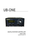
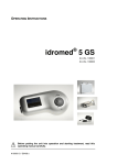
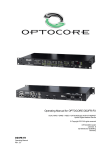
The following figures show the LED Spot W from both the front and rear view.
The water connections, mounted on the back of the unit, are available with either angled or
straight fittings (see chapter 6).
1
3
2
4
1
LED Spot W – rear view
LED Spot W – front view
1 Threading, from the side
4 Sub-D plug (15-pin)
(4 x, M 3, 4 mm deep)
2 Light-emitting aperture
(with protective glass)
3 Water connections
Note
The appropriate water connections (straight / angled) are already
mounted at the time of delivery.
6
#47301e1
3
Safety Notes
General Notes
General Notes
Familiarity with all basic safety regulations is
the prerequisite for safe handling and problem-free use of the LED Spot W.
These Operating Instructions contain the
most important notes for operating the unit in
a safe manner.
The Operating Instructions, especially the
Safety Notes, must be observed by everyone
that works with the unit.
In addition, all applicable rules and regulations on accident prevention for the use area
must also be observed. DIN EN 62471: 2008
("Photobiological safety of lamps and lamp
systems") and BGI 5006 (Oct. 2006) are referred to here.
The proprietor must check the safetyconscious work performance of personnel at
regular intervals.
In accordance with the workplace safety
regulations, the proprietor is advised to make
a reasonable and sufficient assessment of
the risks arising from the use of the LED
Spot W. You must ensure that adequate control measurements are maintained in order to
eliminate or minimise these risks. You can
use the information contained in these Operating Instructions when making the risk assessment.
Risk Group
Risk Group
DANGER
sDanger
Improper use can endanger the health of the user or of third parties
(severe skin or eye damage)!
The Hönle LED Spot W is subject to the standard DIN EN 62471:2008 ("Photobiological
safety of lamps and lamp systems"). It is classified as belonging to Risk Group 3, which requires special safety measures to be observed when operating it. These are described in
detail in the stated DIN EN standard.
Due to the size of the LED Spot W, it is not possible to directly label the unit. The proprietor
must therefore ensure that appropriate identification of the danger area is made in immediate vicinity of the LED Spot W.
#47301e1
7
LED Spot W
Obligation of
Personnel
Obligation of Personnel
Persons, who are entrusted to work with the LED Spot W are obliged, before starting work
to:
Dangers from
Handling the
Unit
observe the regulations on work safety and accident prevention,
read the safety chapter and the warning notices in these Operating Instructions and to
observe them at all times during operation,
in particular, to observe the safety measures in of DIN EN 62471: 2008 ("Photobiological
safety of lamps and lamp systems") and observe BG 5006.
Dangers from Handling the Unit
The LED Spot W is assembled according to the technological state-of-the-art and recognised safety standards.
The following potential dangers can occur:
Danger from electrical current
Danger from UV radiation (actinic UV, close UV)
Danger from blue light (300 – 700 nm)
Danger from heat (eyes, skin)
The unit must be used only under the following circumstances:
When wearing personal safety
equipment to protect the eyes and
skin, in case complete shielding of
the UV radiation cannot be ensured.
Goggles should conform the standard EN 170 (max. spectral transmission (365 nm) 0.3%), and should
afford protection from radiation, both
directly and from the side.
The LED Spot W must be operated
only by persons who have been instructed in all the safety precautions.
The LED Spot W must be set up and
operated in such a way that persons
are not subjected to direct or indirect
radiation. UV-absorbent plastics or
metal sheet can be used as shields.
The LED Spot W must be used only
when it is in flawless condition in terms
of safety. Operation is not permitted
when there is visible damage to the
housing, water hoses, supply cables or
the mains adapter.
Warning notices must be affixed at
the workplace and at all entrances to
the work area.
Proper functionality of the entire cooling unit must always be ensured.
All relevant regulations on accident
prevention and on the handling of units
belonging to Risk Group 3 must be observed.
Under no circumstances must the
LED Spot W be operated in explo-
DANGER
8
sion-protected areas or in the proximity of flammable materials, gases
or liquids.
Danger
Improper use can endanger the health of the user or of third parties
(severe skin or eye damage)!
#47301e1
Intended Use
Intended Use
The LED Spot W is a high-intensity
UV irradiation device for irradiating large areas from a close distance.
Any other or additional usage is regarded as
improper use, and is thus dangerous.
The unit must be used indoors only. Outdoor
use is not permitted.
The operator must operate the unit only in
accordance with the usage notes in these
Operating Instructions.
The LED Spot W must not be used for medical or therapeutic purposes, for skin-tanning,
or in other medical equipment.
DANGER
#47301e1
Danger
There is acute danger of becoming blind if you look directly into the
radiation outlet aperture!
If improperly handled, UV radiation can damage skin and eyes! It can
lead to severe sunburn or to inflammation of the retina and conjunctiva, and possibly to skin cancer.
9
LED Spot W
4
Organisational
Measures
Safety Regulations
Organisational Measures
The functions of all the existing safety equipment must be inspected regularly before the
start of work or of each new shift. Look for outwardly visible damage.
Informal
Safety Measures
Informal Safety Measures
The general and local regulations on accident prevention and environmental protection must
be provided and observed as a supplement to the Operating Instructions.
Checking the Water Lines
Checking the
Water Lines
Danger from
Electrical
Power
Water lines, connections and couplings of the water cooling must be regularly checked for
leak-tightness.
Danger from Electrical Power
The electrical equipment on the LED Spot W must be inspected regularly.
Inspection before starting work:
Check all components of the unit for outwardly visible damage
Check that all electric cables are in flawless condition
DANGER
Danger from
UV Irradiation
Loose connections must be repaired immediately, and damaged cables must be
replaced.
Danger
There is danger of direct or indirect contact with electricity!
Danger from UV Irradiation
The LED Spot W emits radiation in the range of 340 - 440 nm, depending on the type. The
optical output power is detailed in the Technical Data chapter. When working with the unit,
the following instructions must also be followed:
10
Personal safety equipment must be
worn to protect the eyes and skin,
unless the UV radiation is completely
screened by structural measures.
Never look directly or indirectly into
the LED aperture.
The LED Spot W must be set up in
such a way that persons are not subjected to direct or indirect radiation.
In the case of workplaces where manual work is performed or in mobile applications, the working area must be
enclosed in an appropriate manner.
#47301e1
DANGER
WARNING
WARNING
Danger
There is acute danger of becoming blind if you look directly into the
radiation outlet aperture!
If improperly handled, UV radiation can damage skin and eyes! It
can lead to skin burns or to inflammation of the retina and conjunctiva, and possibly to skin cancer.
Warning
UV radiation can cause material damage to electronic components.
When used in the vicinity of the LED Spot W, these components
must be protected from UV radiation.
Warning
UV radiation accelerates the ageing of materials.
UV-sensitive objects and surfaces must therefore be protected from
radiation.
Note
Protective articles are listed in the chapter "Ordering Data for Units,
Replacement Parts and Accessories " .
Danger from
Heat
Danger from Heat
When operating the LED Spot W, take the following thermal risks into account.
The LED Spot W can heat up to a temperature of 55 °C during operation.
There is a risk of burns. It must be ensured that the units cannot be touched.
The tightly bundled radiation of the LED
can lead to heating-up of the radiated
surfaces, especially dark surfaces.
There is a risk of burns.
Under no circumstances must the unit
be operated in the vicinity of flammable
DANGER
#47301e1
or explosive materials, gases or liquids.
There is an acute risk of fire or explosion.
To protect against the danger from heat,
the same measures must be taken that
are effect against the Danger from UV Irradiation (see the chapter Danger from
UV Irradiation).
Danger
The LED Spot W emits highly-intensive, bundled radiation. Improper
use can endanger the health of the user or of third parties (severe
skin or eye damage)!
11
LED Spot W
Warranty and
Liability
Warranty and Liability
The Dr. Hönle AG "General Conditions of Sale and Delivery" always apply. They are available to the user upon signing the contract, at the latest.
Dr. Hönle AG assumes no liability whatsoever for damages that can be attributed to one or
more of the following causes:
Maintenance
and Fault Removal
Improper use of the LED Spot W
contrary to its intended use
Contamination of the quartz glass
pane of the LED Spot W
Incorrect assembly, commissioning
or operation of the
LED Spot W
Contamination of the water-cooling
element as a result of using unsuitable or contaminated coolant.
Failure to observe notes in the Operating Instructions
Unauthorised structural modification
of the LED Spot W
Failure of the cooling unit and/or operation of it that is non-compliant with
the specified operating conditions
(see Technical Data)
Effects of foreign objects or mechanical damage (caused by blows,
jolts, etc.)
Disastrous occurrences
Acts of God
Maintenance and Fault Removal
All necessary maintenance tasks are described in the chapter Service, Maintenance
and Cleaning". Carrying these out ensures
reliable operation.
Should a fault occur in the unit that cannot
be rectified with the help of the Operating Instructions, then Dr. Hönle AG Customer Service must be contacted.
Parts that are not in flawless condition must
be exchanged immediately.
Use only original replacement and wear
parts.
There is no guarantee that other manufacturers’ parts are designed and manufactured
WARNING
WARNING
12
to meet the required standards of robustness
and safety.
No alterations, additions or modifications
must be made to the LED Spot W without the
permission of Dr. Hönle AG.
Contact address for claims under warranty,
repair and replacement part service:
Dr. Hönle AG
UV-Technologie
Lochhamer Schlag 1
D-82166 Gräfelfing / Munich, Germany
Tel.: +49 (0)89 / 856 08-0
Fax: +49 (0)89 / 856 08-148
E-mail: [email protected]
Website: www.hoenle.de
Warning
No repairs or alterations must be made to the unit except those described in these Operating Instructions.
Warning
Only original Dr. Hönle AG replacement parts and wear parts must
be used.
#47301e1
5
Transport, Storage, Delivery
Scope of Delivery of the LED Spot W:
-
Scope of Delivery
LED Spot W
Operating Instructions (possibly on a CD)
The delivered pars must be inspected for completeness and damage or other issues.
Any damage that has been ascertained must be documented at once, and reported to the
dealer or to Dr. Hönle AG without delay.
The following components are also necessary to operate the LED Spot W:
-
bluepoint LED HP component
LED Spot W connection cable
filter unit
cooling unit
water connections (hoses, couplings, etc.)
Note
Please dispose of the packaging material in an environmentally responsible manner.
It may be possible to reuse it.
It is recommended to keep the packaging material, in case the unit
has to be sent by post or otherwise transported.
#47301e1
13
LED Spot W
6
General Information
Installation, Commissioning and Operation
General Information
It is imperative to comply with the specified operating conditions for the water
cooling (see the chapter Water Connection).
The LED Spot W must be mounted on a
stable fixture.
The ambient temperature for operating
the LED Spot W must not exceed a
maximum of 35 °C.
Without exception, the LED Spot W must
only be connected or disconnected with
the bluepoint LED HP switched off! If the
LED Spot W is disconnected during ongoing operations, this could cause damage to the device and/or a component.
DANGER
Do not touch the contact pins in the
LED Spot W plug connector with your
fingers (danger of ESD damage).
Protect the LED Spot W against chemical
vapours and cleaning agents.
Only operate the LED Spot W in dry
rooms. Rel. humidity max. 70% (noncondensing). Open-air operation is not
permitted.
Before switching on, check to ensure that
all plug-type connectors, incl. water connections, are properly seated and tight.
It should be observed that the LED Spot
W is not exposed to any spray water.
Furthermore, no condensation may form
on the surface of the spotlight.
Danger
Sufficient cooling must be provided for when installing the LED Spot
W. It is forbidden to operate the device in the immediate vicinity of
flammable objects, liquids or gases.
The dimensions for the LED Spot W can be found in the dimensional drawings in the chapter 9 Technical Data).
14
#47301e1
Electrical Connections
The supply with electric current and activation of the LED Spot W is accomplished via the
bluepoint LED HP. For detailed information on the electrical connections, refer to the bluepoint LED HP Operating Instructions in the chapter "Electrical Connections".
WARNING
Warning
The LED Spot W must only be used with the bluepoint LED HP component.
WARNING
Warning
Connecting and disconnecting of the LED Spot W must only be done
when the bluepoint LED HP is in a switched off state. Use the main
switch on the back of the device for this purpose. Otherwise damage
could occur to the LED Spot W or the bluepoint LED HP.
Water Connection
It is imperative to comply with the following connection information/operating conditions for
the LED Spot W and the filter unit:
Filter unit connections
¼‘‘ BSP inside thread
LED Spot W connections
coupler socket NW 5 BA (self-closing)
Max. pressure:
3.5 bar
Min. flow rate:
2 l/min
Max. inflow water temperature:
25 °C
Min. inflow water temperature
16 °C
Coolant
demineralised water
Max. distance filter unit – LED Spot W
1m
Make sure that no condensation may form on the surface of the spotlight.
The filter unit for the coolant must always be in flawless condition. It must be
checked daily and, if necessary, replaced without delay.
The coolant must be regularly inspected for contamination and, if necessary, replaced entirely.
When connecting or disconnecting, it is imperative to ensure that no water gets
onto the LED Spot W or into the connector plug.
WARNING
#47301e1
Electrical Connections
Water Connection
Warning
Condensation may lead to destruction of the device!
It is absolutely essential to avoid any formation of condensed
water on the surface of the LED Spot W. The proprietor has
therefore to provide adequate climatic conditions at site (air
humidity, temperature). The temperature of the cooling water
may be adjusted, if necessary.
15
LED Spot W
WARNING
Warning
The cooling parameters must be adhered to without fail, otherwise
damage could occur to the LED Spot W.
Connecting the LED Spot W via the Adapter:
Connecting the
LED Spot W via
the Adapter
The LED Spot W is connected by means of the adapter (# 45979):
Before connecting the LED Spot W, ensure that the bluepoint LED HP has been switched off
( main switch (1) in position 0).
1. Insert in the adapter (3) into the LED channels (2).
2. Tighten the securing nuts (4) for the adapter.
3. Insert the LED Spot W plug connector (5) and tighten it.
In the next step the water cooling will be installed.
2
1
5
3
4
16
#47301e1
Connecting the Water Cooling to the LED Spot W
In the following, a typical connection schematic is shown for a water cooling circuit with three
connected LED Spot W:
Water cooling unit
1. Connect the inflow line of the cooling unit to the filter unit.
2. Hook up the connector of the filter unit with the LED Spot W (max. distance = 1 m).
3. Hook up the return line of the cooling unit with the second connector on the LED Spot W.
The device is now ready for operation and can be switched on via the main switch (1).
WARNING
WARNING
#47301e1
Warning
Condensation may lead to destruction of the device!
It is absolutely essential to avoid any formation of condensed
water on the surface of the LED Spot W. The proprietor has
therefore to provide adequate climatic conditions at site (air
humidity, temperature). The temperature of the cooling water
may be adjusted, if necessary.
Warning
All connections must be checked for leak-tightness immediately after
being switched on for the first time and then regularly thereafter. If
there are any leaks, the system must be switched off immediately. It
may only be switched on again after all flaws have been corrected
and the released water has dried up completely.
17
LED Spot W
7
General Information
Service, Maintenance and Cleaning
General Information
Service, repair and cleaning work may only be performed by authorised personnel.
When performing service, maintenance and cleaning, it must be ensured that the outlet
aperture of the LED Spot W does not become dirtied by fingerprints or other contaminants.
Likewise, no sprayed water may contact the surface of the LED Spot W.
In general, work should be performed with a clean cloth or clean gloves.
Only touch the LED Spot W on the metal housing.
If necessary, clean the outlet aperture of the LED Spot W when it is cold, using a clean
cloth and alcohol.
Note
Contamination of the outlet aperture due to fingerprints or the like reduce the UV output of the LED Spot W.
Service
Service
The following service work is performed on the LED Spot W:
Daily:
Inspection of the LED Spot W for damage to and contamination of the outlet aperture.
If necessary, the outlet aperture must be cleaned; see the chapter "Cleaning".
Inspection of the filter unit
Inspection of the leak-tightness of the water connections
As needed / at regular intervals (dependent on operating conditions)
Cleaning
Replacement of the filter unit (see the chapter Filter Change).
Cleaning
Note
When cleaning, do not use any aggressive or abrasive cleansing
agents.
If operated in a dusty environment or in the presence of fumes from adhesives, the radiation
emission surface of the LED Spot W can become contaminated. This diminishes the UV intensity.
18
Clean the radiation aperture surface with a clean, lint-free cloth and alcohol.
#47301e1
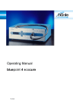
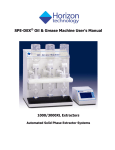
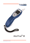
Filter Change
Filter Change
1. Switch off the bluepoint LED HP (main switch in position 0).
2. Switch off the cooling unit and detach it from the mains supply.
3. Counterrotate both of the red shutoff valves (1) of the filter unit by 90 ° to the direction of
flow (= position OFF).
4. Unscrew the reservoir container (2) from the filter unit and remove it. When doing this,
watch out for remaining water that might leak out of the reservoir container and collect in
an appropriate vessel if necessary.
5. Remove the attachment screw (3) and filter (4).
1
4
1
Shutoff valve
2
Reservoir container
(with O-ring)
3
Attachment screw
4
Filter
3
2
6. Put the new filter in place and fasten it securely with the attachment screw.
7. Screw the reservoir container onto the filter unit again.
8. Rotate both of the shutoff valves of the filter unit into the OPEN position again.
9. Reconnect the cooling unit to the mains supply again and switch it on.
10. After first switching on the system again, check the filter unit for leak-tightness.
#47301e1
19
LED Spot W
8
Ordering
Ordering Data for Units, Replacement Parts and Accessories
Ordering
Order replacement parts from our replacement-parts service at the following address:
Dr. Hönle AG
UV-Technologie
Lochhamer Schlag 1
D-82166 Gräfelfing / Munich, Germany
Tel.: +49 (0)89 / 856 08-0
Fax: +49 (0)89 / 856 08-148
LED Spot W
LED Spot W
Designation
Article/Order Number
LED Spot W 365 nm
LED Spot W 375 nm
LED Spot W 385 nm
LED Spot W 395 nm
LED Spot W 405 nm
Replacement
Parts / Accessories
45900
45901
45902
45903
45904
Replacement Parts / Accessories
Designation
Article/Order Number
bluepoint LED HP component
Adapter for bluepoint LED 4-1
UV warning sign
Operating Instructions (German/English) on CD
Cooling unit
Filter unit
Insert for filter unit
Water connection set, straight fittings
Water connection set, angled fittings
Connection cable 1.5 m
Connection cable 2.5 m
Connection cable 4.0 m
Connection cable 1.5 m; 90°
Connection cable 2.5 m; 90°
Connection cable 4.0 m; 90°
Connector for hose DN5 BA-D = 6
45250
45979
45890
47301
46700
46825
46726
46820
46821
46811
46812
46813
46815
46816
46817
46705
Warning
Only original replacement parts from Dr. Hönle AG may be used. If
any third-party parts are used, then the operational safety of the
LED Spot W cannot be ensured.
20
#47301e1
9
Technical Data
General Data
General Data
Typical LED service life
> 10,000 hours*
Wavelengths in nm
365
375
385
395
405
Type intensity in mW/cm² **
650
1200
1500
3900
4200
Supply
90 V – 264 V
(Tolerance: +/- 5 nm)
47 Hz – 63 Hz
Input current, max.
2.4 A
Connected load
max. 200 W
Dimensions of LED Spot W
without connections (H x W x D)
approx. 60 x 50 x 17 mm
Weight
approx. 350 g (without water)
* Depending on the operating conditions and cooling conditions
** Measured using a Hönle LED measurement head for UV meters
Water Cooling Operating Conditions
It is imperative to comply with the following connection information/operating conditions for
the LED Spot W and the filter unit:
Filter unit connections
¼‘‘ BSP inside thread
LED Spot W connections
coupler socket NW 5 BA (self-closing)
Max. pressure:
3.5 bar
Min. flow rate:
2 l/min
Max. inflow water temperature:
25 °C
Min. inflow water temperature
16 °C
Coolant
demineralised water
Max. distance filter unit – LED Spot W
1m
Make sure that no condensation may form on the surface of the spotlight.
The filter unit for the coolant must always be in flawless condition. It must be
checked daily and, if necessary, replaced without delay.
The coolant must be regularly inspected for contamination and, if necessary, replaced entirely.
When connecting or disconnecting, it is imperative to ensure that no water gets
onto the LED Spot W or into the connector plug.
WARNING
#47301e1
Water Cooling
Warning
Condensation may lead to destruction of the device!
It is absolutely essential to avoid any formation of condensed
water on the surface of the LED Spot W. The proprietor has
therefore to provide adequate climatic conditions at site (air
humidity, temperature). The temperature of the cooling water
may be adjusted, if necessary.
21
LED Spot W
Warning
The cooling parameters must be adhered to without fail, otherwise
damage could occur to the LED Spot W.
Dimensional drawing of the LED Spot W – angled version
Dimensional
drawing of the
LED Spot W –
angled version
22
#47301e1
Dimensional drawing of the LED Spot W – straight version
Dimensional
drawing of the
LED Spot W –
straight version
#47301e1
23
LED Spot W
Dimensional Drawing of the Filter Unit
Dimensional
drawing of the
filter unit
24
#47301e1
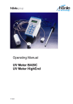
Optical Data
Optical Data
Typical intensity distribution as a percentage (2 mm spacing)
100
90
80
70
Intensity 60
50
40
30
20
10
0
y-axis
in mm
10
-5
-20
-14
-8
-2
4
10
16
-20
100-105
90-100
80-90
70-80
60-70
50-60
40-50
30-40
20-30
10-20
0-10
x-axis
in mm
Typical intensity characteristics over operating distance (in %; distance in mm)
#47301e1
25
LED Spot W
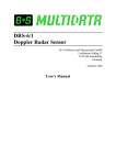
Relative spectral irradiance
Typical optical output dependent on the LED temperature at 100 % set value
For further information on the different operating modes, please refer to the operating instructions of the bluepoint LED/bluepoint LED HP, chapter „LED mode“.
Fig. 1: LED Spot W 375 nm
Fig. 2: LED Spot W 405 nm
26
#47301e1