1
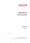
AMS42/84-USB
5B amplifier measurement system (USB)
All-In-One Measurement System.
Compact or 19 inch.
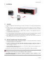
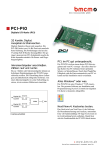
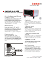
The AMS42/84-USB, a complete solution: amplifier technology and data acquisition. A highquality USB data acquisition system is already integrated. Available in a robust aluminum housing
as a mobile tabletop unit (AMS42-USB) with
skid-proof, tip-up feet or as a stationary version
(AMS84-USB) for 19'' rack systems.
Modular concept.
Equip individually. Be flexible.
The AMS device is equipped with cassettes, on
which the required 5B measuring amplifiers are
mounted. The variety of available 5B modules allows for the optimum adaptation of the
AMS42/84-USB to any special measuring task.
Choose connector.
Mount 5B amplifier. Done.
The available plug-in cassettes have different
connectors on the front panel. Depending on the
sensor or signal to be connected, the suitable cassette can be chosen. Now the 5B module only has
to be fixed on the cassette and be integrated in the
AMS.
Clearly safe.
The galvanic isolation provided by the 5B modules guarantees interference-free operation and
protects the DAQ system and the PC against high
potentials.
8/16 analog inputs.
250kHz. 16 bit.
Signals are connected at 8/16 analog inputs with
16 bit resolution and 250kHz total sampling rate
so that even slightest peaks of high-frequent signals do not remain undetected.
4 digital inputs/outputs each.
1 counter.
Digital states are recorded or set at four digital inputs and outputs each. For pulse measurements,
an additional isolated counter input is provided.
Plug & Play with USB.
The connection to the PC is realized via USB.
The AMS42/84-USB provides all typical USB
features (e.g. Plug&Play, Hot-Plug).
Open for everyone.
Widely supported: The amplifier measurement
system can be used under Windows® 7/XP as
well as under MAC OS X, Free BSD and Linux.
The complete software for installation and programming of the AMS42/84-USB is included for
free. The device is supported by NextView® 4,
the software for data acquisition and analysis.
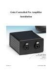
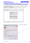
Functional diagram
AMS42/84-USB
1
Installation
1.1
Assembly
a) Equip the AMS42/84-USB with the plug-in cassettes (see chapter 7.2) carrying the required 5B modules.
b) Carefully push the cassette along the guide bars of the relevant slot until the 7-pole pin connector of
the cassette and the pins of the 5B module are plugged into the corresponding connectors on the AMS
backplane.
c) If using the option AMS42-EXT8 for the AMS42-USB (see chapter 7.4), the additional cassettes 9-16
are mounted on the back of the device.
d) For a tight installation, fix the front panel at both ends with screws to the housing. Bridge unneeded
slots by a blank panel (AMS-K-BLANK) to protect the device against outside influences.
e) If the AMS84-USB is mounted to a 19'' rack system, the relevant input wiring should be prepared first
before attaching the device to the rack system with screws.
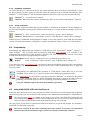
1.2
Software installation and start-up procedure
a) Install the bmcm driver package (see chapter (see chapter 6.1.1) on the PC/notebook before connecting
the AMS42/84-USB to a free USB interface.
b) Connect an external power unit to the 3-pole DIN coupling for 9-40V power supply (use a supply cable with a cross sectional area >1mm2) and turn on the AMS42/84-USB by pressing the switch to "1"
(ON) (see chapter 3.1 and 3.3).
c) Start the Plug&Play installation (see chapter 6.1.2). If necessary, further software components can be
installed now, as described in chapter 6.
d) Signals are connected at the specific female connector of the respective AMS cassette panel.
• To change the cassettes, the power of the AMS device must be turned off!
• If the AMS system is operated standalone, additional grounding to enhance shielding is recommended but not mandatory.
Page 2
AMS42/84-USB
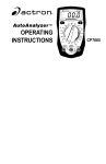
2 Block diagram
3 Connections / Assignments
All available connectors and operating
elements of the AMS42/84-USB are accessible on the right-hand side of the
device front.
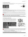
3.1
Switch
The amplifiers of the AMS42/84-USB
are turned on (press "1") and off (press
"0") with the switch.
The green LED "ON AMPL" indicates
the supply of the 5B modules.
The DAQ unit is supplied by the PC.
3.2 LEDs
The two LEDs on the front of the device indicate the following states:
LED
"ON_AMPL."
"ON"
"STATE"
Information
indicates the supply of the 5B modules with 9-40 DC IN (switch on "1" position)
indicates the supply of the USB data acquisition unit (5V) by the PC
signalizes the transmission of commands to the PC
3.3 USB
The standard USB connector (type B) serves for the PC connection of the data acquisition unit
integrated in theAMS42/84-USB. Power supply is also provided via the USB interface.
Page 3
AMS42/84-USB
3.4 Power supply "DC In"
The installed 5B modules are supplied with power (9..40V) via the 3-pole DIN plug. A power supply unit
ZU-PW70W (24V, 2.92A DC) is optionally available.
Pin
Assignment
1
2
3
n. c.
ground (GND)
9-40V DC
3.5 Analog channels
8 (AMS42-USB) or 16 (AMS84-USB or AMS42-USB with option AMS42-EXT8) analog signals can be connected to the amplifier inputs available at the respective connectors of the cassette panels. Their assignment
is illustrated in the data sheet of the AMS-K-xxx cassettes.
Depending on the application, the shield of the analog input cables can be applied to ground or 0V. Be sure
to connect at one end of the cable only. Run the signal ground separately if possible. Lay input cable separately if possible.
Measurements can be effected on various potentials. The potential deviations, however, should not exceed 60V DC (according to VDE Association of German Electrical Engineers).
3.6 Digital inputs and outputs
The AMS42/84-USB features 4 digital inputs and outputs each
(low: 0V..0.7V; high: 3V..5V) and an isolated counter input. The
5V auxiliary voltage at pin 6 can be used e.g. for sensor supply.
All connections are led to the 15-pole D-Sub female connector
on the back of the device. The pin assignment is as follows:
Pin
USB-AD16f
Pin
USB-AD16f
1
9
2
10
3
11
4
12
DOut 1
DOut 2
DOut 3
DOut 4
DIn 1
DIn 2
DIn 3
DIn 4
5, 13
6
7
14
8, 15
DGND
VUSB (4-5V; max. 20mA)
counter input low
counter input high
n. c.
• The digital lines are protected by 1kΩ resistors. If the input voltage is not within the permitted
voltage range of 0V..5V, the device may be damaged.
• The digital inputs and outputs are not galvanically isolated except for the counter.
• The digital ground (DGND) is connected with the PC ground.
Page 4
AMS42/84-USB
4 Interfacing examples for the digital lines of the AMS42/84-USB
The following basic connection examples demonstrate the use of the digital inputs and outputs and the connection of a counter to the AMS42/84-USB. The pin assignment of the 15-pole D-Sub female connector is
described in chapter 3.
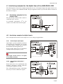
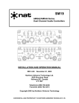
4.1
Interfacing examples for the
counter input
The galvanically isolated 16-bit counter is
connected at pin 7 and 14.
At maximum performance (216-1), the
counter is reset and starts from zero again.
4.2 Interfacing examples for digital inputs
The 3.9kΩ pull-down resistor sets the input to low if no voltage is applied there.
4.2.1
Connecting an optocoupler
Optocouplers provide optimum protection
at each input line. With them, it is possible
to connect higher voltages and to protect
the hardware from being destroyed.
In this regard, please also see application
examples of the optocoupler you use.
Optocoupler boards with 8 or 16 inputs
are available at bmcm.
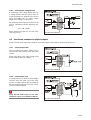
4.2.2 Connecting a push-button /
switch
Please make sure to use a push-button with
debounce protection, because otherwise
several pulses might be recorded.
The 3.9kΩ pull-down resistor is absolutely
necessary to create a defined low signal!
Page 5
AMS42/84-USB
4.2.3
Connecting a voltage divider
If connecting a DC voltage higher than 5V,
a voltage divider must be used so that 5V
at the maximum are applied at the device
input. Exceeding the 5V input voltage
might cause damages to the device.
The relation between the two resistors to be
used is calculated with the following formula:
U/U1= (R1+R2)/R1
Input voltages less than 5V are also sufficient (high ≥3V).
4.3 Interfacing examples for digital outputs
Serial resistors in the output lines limit the current and protect the hardware from being destroyed.
4.3.1
Connecting an LED
Only so-called low-current LEDs can be
used, because they already work with 1mA
current.
Please also observe the total current listed
in the technical data (see chapter ).
4.3.2
Connecting a relay
A connected relay is ideal to switch higher
currents. Since the field coil of the relay
requires a higher current than provided by
the measurement system at one line, a transistor is connected ahead.
Relay boards with 8 relays or 16 semiconductor relays are available at bmcm.
Page 6
AMS42/84-USB
4.3.3
Connecting a lamp
A transistor can be used to switch higher
loads. The selected transistor must comply
with the maximum switchable current.
The figure on the right shows an application with a maximum current of 100mA.
5 AMS backplane
The AMS -backplane provides 8 slots for 5B modules and the AMS-K-xxx plug-in cassettes (see chapter 7.2)
carrying the 5B modules. In the AMS84-USB, two backplanes are integrated.
If the AMS42-USB is used with the optional add-on AMS42-EXT8 (see chapter 7.4), eight slots each are
available on the front and on the back of the device.
5.1
Ground-to-ground resistance
The ground-to-ground resistance is required when the output ground is not electrically connected with the
power supply ground. If the jumper (see fig. above) on the analog backplane is closed, the output switches of
the modules are switched through.
In the case of electrically connected systems (e.g. PC), this jumper represents a high-resistance bridge
(1kΩ) and may generate a hum loop!
Page 7
AMS42/84-USB
5.2 Module pin assignment
The pin assignment on the right shows the top view of the module backplane (see chapter 5).
The pin assignment corresponds to the 5B modules of Analog Devices®,
BURR BROWN® etc. However, an additional 0EX pin has been introduced, which is particularly suitable for ungrounded shielding. This is a
specific assignment of BMC Messsysteme GmbH. This pin is not connected in modules of other manufacturers.
5.3 Fuse
The fusing of the AMS backplane is effected on the backplane (see chapter 5) with one reversible semiconductor fuse. In case of overload, it turns of. To make the fuse work effectively again, first remove the
cause for overload before disconnecting the power supply of the AMS42/84-USB.
5.4 Connection for AMS cassettes
The cassettes are connected to the AMS backplane via 7-pole pin connectors, leading the
input signals connected at the cassette panel to the backplane. The assignment of the 7-pole
female connector on the board is illustrated in the figure on the right-hand side.
Page 8
AMS42/84-USB
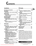
6 Software installation
All software and documentation available for the AMS42/84-USB are integrated on the "Software
Collection" CD included with delivery. When inserting the CD, a CD starter opens automatically
(otherwise: start openhtml.exe).
AMS42-USB
Change to the product page of the AMS42/84-USB by selecting the entry "Products" in the CD
starter and then the hardware ("AMS42-USB" or "AMS84-USB") listed under the interface
"USB".
For detailed information about installing or operating the software, please see the corresponding
manuals. The Adobe Acrobat Reader is required to open the documentation in PDF format.
You can run the installation directly from CD. If your browser prevents this, first save the
setup program to hard disc before running it separately.
Software Software product Notes
Device
driver
Programming
BMCM-DR
(driver package)
STR-LIBADX
STR-LIBADX-EX
SDK-LIBAD
Operating
program
NV4.5
1. install driver package to hard disc
2. Windows® Plug&Play installation
ActiveX control for hardware independent programming
example programs for LIBADX ActiveX control
SDK with example programs for C/C++ on
Windows®, MAC OS X, FreeBSD, Linux
measuring software NextView®4 available in the
Standalone versions:
• Lite:
"slim" version with basic functions
full version with complete functional
• Pro:
range
• Analysis: version for the analysis of stored
measuring data
Documentation
IG-BMCM-DR
(driver installation manual)
IG-LIBADX
(installation / programming manual)
UM-LIBAD4
(installation / programming manual)
DS-NV4
(data sheet)
UM-NV4
(user manual)
"First steps" in the NextView®4
demo project (displayed when first
starting the software)
NextView®4 can be used for free as a fully functional 30-day trial version. After purchasing the
software, all projects, measurement files, and
settings can still be used.
6.1
Driver installation
Under Windows®, the driver installation is always required for the AMS42/84-USB. Only then
additional software can be installed. To make sure the installation is done correctly, please follow
the instructions in the order as described below.
Under MAC OS X, FreeBSD and Linux, driver installation is not necessary.
6.1.1
Install driver package
The prior installation of the bmcm driver package BMCM-DR to the hard disc of your PC makes the driver
search for Windows® much easier. Especially in case of driver updates, only the new driver package has to
be installed, the hardware automatically uses the new version.
The link to install the driver package is located on the AMS42/84-USB product page of the "Software Collection" CD.
Page 9
AMS42/84-USB
6.1.2
Plug&Play installation
As soon as the device is connected to the PC, the system announces the new hardware ("USB-BASE"). Since
the driver package has been copied to hard disc before, the hardware will be installed automatically under
Windows® 7. Under Windows® XP, the automatic hardware detection is started by selecting the following:
- Windows® 7: no specifications required
- Windows® XP: "Install the software automatically" (SP2: do not connect with Windows® Update!)
6.1.3
Check installation
The entry "Data Acquisition (BMC Messsysteme GmbH)" is included in the Windows® Device Manager after successful installation displaying the installed bmcm hardware. To open the Device Manager, proceed as
follows:
- Windows® 7: Start / Control Panel / System and Security / System / Device Manager
- Windows® XP: Install Start / Control Panel / System / TAB "Hardware" / button "Device Manager"
Double click the "USB-BASE Analog/Digital I/O Board" to show the properties of the USB data acquisition
system. For general information, existing device conflicts and possible sources of error, see TAB "General".
6.2 Programming
Programming the AMS42/84-USB (installed as "USB-AD16f") with Visual Basic®, Delphi®, Visual C++™
under Windows® 7/XP is possible with the hardware independent STR-LIBADX. It is available on the
AMS42/84-USB product page of the "Software Collection" CD. After installation, the ActiveX control must
be loaded into the respective programming environment.
- Visual Basic®: menu "Project / Components", entry "LIBADX Object Library 4.0"
- Delphi®:
menu "Components / Import ActiveX", entry "LIBADX Object Library 4.0"
If you select the entry STR-LIBADX-EX listed directly under the installation program of the corresponding
ActiveX control, you can install example programs (with source code) demonstrating how to apply the
ActiveX control.
Programming the AMS42/84-USB (installed as "USB-AD16f") under Max OS X and Unix
(FreeBSD, Linux) with C/C++ is done by means of the LIBAD4 programming interface.
The SDK-LIBAD for the respective operating system (also Windows®) is included on the product
page of the AMS42/84-USB. For further information about how to integrate the SDK in the programming environment, please see the corresponding programming manual UM-LIBAD4.
Using the LIBAD4 requires advanced programming experience!
6.3 Using AMS42/84-USB with NextView®4
Install the fully functional trial of the professional software NextView®4 for measurement data acquisition
and processing to directly test the features and functions of the AMS42/84-USB (installed as "USB-AD16f").
The setup program NV4.5 is available on the product page of the card. When first starting the software, request a license number with the option "Request 30 days free trial version" being checked and
select your DAQ system (USB-AD16f) in the following dialog "Device Setup".
The start project of NextView®4 contains first instructions about how to operate the program. For detailed information, an online help is provided.
The trial is valid for 30 days after requesting the license number. If a license is not purchased
within this period, the functional range of NextView®4 will be considerably cut down!
Page 10
AMS42/84-USB
7 Supplementary products for the AMS42/84-USB
7.1
5B modules (MA series)
The 5B measuring amplifiers from bmcm allow for the professional
signal adjustment to a data acquisition system.
The amplifier output is ±5V or 0..5V. Most of the modules are electrically isolating and provide sensor supply.
The following 5B modules from bmcm are available:
Product
Description
MA-UNI
MA-UI
MA-U
MA-FU
MA-DFI
MA-FI
universal amplifier with galvanic isolation for U, I, R, thermocouple, strain gauge, LVDT
multi-range amplifier with galvanic isolation for U, I
voltage measuring amplifier with galvanic isolation, 50kHz bandwidth
frequency/voltage converter with galvanic isolation
digital filter module with galvanic isolation, 60dB/oct.
filter module with galvanic isolation, 30dB/oct.
7.2 Plug-in cassettes (AMS-K series)
The amplifier system can be individually equipped with 8 (AMS42USB) or 16 (AMS84-USB or AMS42-USB with option AMS42-EXT8)
plug-in cassettes.
Each cassette is equipped with the relevant 5B module and suitable input connector.
The suitable input connector on the front panel guarantees for the relevant connection to be available when exchanging the cassette.
The following cassettes are available:
Product
Description
AMS-K-BIN5
AMS-K-BLANK
AMS-K-BNC
AMS-K-CO5
AMS-K-THK
cassette with panel and 5-pole Binder female connector (712 series)
blank panel
cassette with front panel and BNC female connector
cassette with front panel and 5-pole terminal connector
cassette with front panel and thermocouple socket (type K)
7.3 AMS-HANDLE, AMS-HANDLE2
For mobile use, the AMS42/84-USB can be equipped with
a lateral, foldaway strap carrying handle (AMS-HANDLE)
or with two stable metal handles at the housing frame
(AMS-HANDLE2).
7.4 AMS42-EXT8, AMS-DIG4
With the add-on option AMS42-EXT8, eight additional analog channels are available (only AMS42LAN16f), and four opto-isolated digital inputs and four relay outputs with the option AMS-DIG4. The additional channels are accessible at the back of the amplifier measurement system.
Page 11
AMS42/84-USB
8 Important notes for using the AMS42/84-USB
•
•
•
•
•
•
•
•
•
The device is only suitable for extra-low voltages - please observe the relevant regulations! For reasons relating to
EMC, it must only be used in closed PC housings. ESD voltages at open lines may cause malfunction.
Only use an electrical isolated power supply unit (with CE).
For cleaning only use non-solvent detergents. The product is designed to be maintenance-free.
For calibration purposes the device must be returned to BMC Messsysteme GmbH.
For reasons relating to CE use shielded cables. Connect the shield to ground at one end only. Close open inputs if
possible. ESD voltages on lines may cause malfunction during operation.
When mounting the cassettes, a connection between power supply ground and chassis of the device is made via
the module screw.
The device ground and the chassis are electrically connected to the chassis of the PC, which is usually also connected to ground. Be sure to avoid ground loops since they will cause measuring errors!
The Gain is adjusted to even values. Therefore, only 64000 values (for 16 bit) of the full range of the converter are
used. As a result, the measuring ranges are slightly larger (e.g. ±5.12V) than the indicated measuring ranges so
that overranges can be recognized
The device must not be used for safety-relevant tasks. With the use of the product, the customer becomes manufacturer by law and is therefore fully responsible for the proper installation and use of the product. In the case of
improper use and/or unauthorized interference, our warranty ceases and any warranty claim is excluded.
Do not dispose of the product in the domestic waste or at any waste collection places. It has to be either duly disposed according to the WEEE directive or can be returned to bmcm at your own expense.
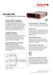
9 Technical data
(typical at 20°C, after 5min., +24V supply)
• Analog inputs
Channels:
8 (AMS42-USB) or 16 (AMS84-USB) inputs galvanically isolated from the PC
Resolution // Sampl. rate // Meas. range:
16 bit // max. 250kHz total sampling rate* // ±5V
Abs. accuracy // Memory depth //Noise:
±2.5mV // only depending on the size of the hard disk of the server PC // ±7 LSB
Surge protection:
±35V (when turned on), ±20V (when turned off), max. ±20mA in total of all input channels!
Input resistance // Input capacity:
1MΩ (with PC turned off: 1kΩ) // 5pF
Zero shift // Gain drop:
±50ppm/°C // ±50ppm/°C
Frequency accuracy // Frequency drift:
max. ±50ppm // max. ±50ppm/°C
* The total sampling rate is the sum of the sampling rates of the individual used channels (e.g. if 5 channels are scanned with 50kHz, the total
sampling rate adds up to 250kHz).
• Digital inputs/outputs
Channels // Level:
Current pick-up per output pin:
Surge protection:
Counter:
4 input and 4 output channels // CMOS/TTL compatible (low: 0V..0.7V; high: 3V..5V)
1mA (with app. 4V level), max. 2.5mA (with app. 3V level)
max. ±5.5V, protected with 1kΩ, max. max. ±20mA in total of all channels!
1MHz, 16 bit, galvanically isolated, 5..12V input voltage
• General data
Power supply:
Galvanic isolation:
Analog connections:
Digital connections:
USB connection:
CE standards:
ElektroG // ear registration:
Max. permissible potentials // Protection:
Temperature ranges // Relative humidity:
Dimensions (W x H x D):
Delivery:
Available accessories:
Warranty:
+9..40V DC, ±5%, min 3W, max. 20W (depends on number of 5B modules used) at 3-pole DIN male
depends on the 5B modules used
different connectors (Phoenix, Binder, BNC, Thermo) on the front panels of the cassettes
all channels at a 15-pole D-Sub female at the device front
standard USB female connector, type B
EN61000-6-1, EN61000-6-3, EN61010-1; for decl. of conformity (PDF) visit www.bmcm.de
RoHS and WEEE compliant // WEEE Reg.-No. DE75472248
60V DC acc. to VDE, max. 1kV ESD on open lines // IP20
operating temp. -25..50°C, storage temp. -25..70°C // 0-90% (not condensing)
AMS42-USB: 23.5 x 13.2 x 25.6 cm3; AMS84-USB: 48.3 x 13.2 x 25.6cm3 (incl. mounting brackets)
device, 1m USB connection cable, "Software Collection" CD, description
plug-in cassettes with front panels and different connectors of the AMS-K series, 8-channel extension
AMS42-EXT8 (AMS42-USB only), extension AMS-DIG4 for 4 opto-isolated digital inputs and 4 relay
outputs, desktop power supply ZU-PW70W (24V, 2.92A DC), D-Sub plug ZU15ST,
3-pole DIN female ZU3DIN, carrying handles AMS-HANDLE, AMS-HANDLE2
2 years from date of purchase at bmcm, claims for damages resulting from improper use excluded
• Software
Software on CD (included):
NextView®4 (optional):
ActiveX Controls LIBADX (hardware independent) for programming on Windows® 7/XP;
LIBAD4 SDK for C/C++ programming on Windows® 7/XP, Mac OS X, Unix (FreeBSD, Linux);
trial version of the measuring software NextView®4 to test and operate the hardware
professional software (versions: Professional, Lite) for the acquisition and analysis of measurement
data on Windows® 7/XP
Manufacturer: BMC Messsysteme GmbH. Subject to change due to technical improvements. Errors and printing errors excepted. Rev. 4.0 11/26/2012
Page 12