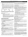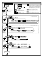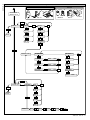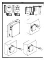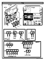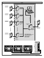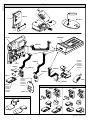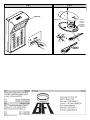
1
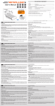
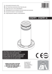
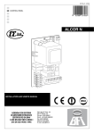
D811373 ver.02 04-04-05
GB ROLLING-CODE / ACCESS CONTROL RADIO TRANSMITTER
8 027908 204530
RTD-CA
TRC 1-2-4 / MITTO 2-4 433MHz
88
88
INSTALLATION AND USER'S MANUAL
Via Lago di Vico, 44
36015 Schio (VI)
Tel.naz. 0445 696511
Tel.int. +39 0445 696533
Fax 0445 696522
Internet: www.bft.it
E-mail: [email protected]
D811373_02
2 - RTD-CA - Ver. 02
D811373_02
MANUALE D’USO
ITALIANO
1) GENERALITÀ
Nel ringraziarVi per la preferenza accordata a questo prodotto, la ditta è certa che da esso otterrete le prestazioni necessarie al Vostro uso.
Leggete attentamente l’opuscolo ”Libretto istruzioni” che lo accompagna in quanto esso fornisce importanti indicazioni riguardanti la
sicurezza, l’installazione, l’uso e la manutenzione. Questo prodotto risponde alle norme riconosciute della tecnica e delle disposizioni relative
alla sicurezza. É conforme alle seguenti direttive europee: 89/336/CEE, 1999/5/CEE e modifiche successive.
Sistema radioricevente ad autoapprendimento, programmabile le cui principali caratteristiche sono:
•
Ricevitore a 512 o 2048 codici
•
Fino a 4 uscite (1 standard + 3 modulari) con riconoscimento automatico dei moduli inseriti
•
Uscite configurabili come monostabile, bistabile, temporizzata, antiaggressione e controllo accessi
•
Programmazione mediante display incorporato
•
Funzioni di controllo accessi
•
Capacità di riconoscere e memorizzare trasmettitori, tessere di prossimità, trasmettitori abilitati al controllo accessi.
•
Compatibile con il protocollo EElink per una rapida installazione e manutenzione.
•
Protezione della ricevente mediante password
2) MANUTENZIONE
La manutenzione dell’impianto va fatta eseguire regolarmente da parte di personale qualificato.
Le trasmittenti MITTO sono alimentate da 2 batterie al litio da 3V (tipo CR2016).
Le trasmittenti TRC sono alimentate da una batteria alcalina da 12V.
Una diminuzione della portata della trasmittente può essere dovuta alle batterie che si stanno scaricando. Quando il led della trasmittente
lampeggia, indica che le batterie sono scariche e devono essere sostituite.
3) DEMOLIZIONE
ATTENZIONE: Avvalersi esclusivamente di personale qualificato.
L’eliminazione dei materiali va fatta rispettando le norme vigenti. Nel caso di demolizione del sistema, non esistono particolari pericoli o rischi
derivanti dai componenti stessi. È opportuno, in caso di recupero dei materiali, che vengano separati per tipologia (parti elettriche - rame alluminio - plastica - ecc.). Per lo smaltimento della batteria riferirsi alla normativa vigente.
USER’S MANUAL
ENGLISH
1) GENERAL OUTLINE
Thank you for buying this product, our company is sure that you will be more than satisfied with the performance of the product. Read the
“Instruction Manual” supplied with this product carefully, as it provides important information about safety, installation, operation and
maintenance.This product conforms to recognised technical standards and safety regulations. It complies with the 89/336/EEC, 1999/5/CEE,
European Directive and subsequent amendments.
Programmable self-learning radio receiver system, having the following main features:
•
Receiver with 512 or 2048 codes
•
Up to 4 outputs (1 standard + 3 modular) with automatic recognition of the modules entered
•
Outputs which can be configured as monostable, bistable, timed, anti-aggression and access control
•
Programming by means of incorporated display
•
Access control functions by means of integrated WRTD board
•
Capable of recognising and memorising transmitters, proximity cards, and transmitters enabled for access control
•
Compatible with EElink protocol for fast installation and maintenance
•
Protection of receiver by means of password.
2) MAINTENANCE
The maintenance of the system should only be carried out by qualified personnel regularly.
The MITTO transmitters are supplied by two 3V lithium battiers (type CR2016).
The TRC transmitters are powered by a 12V alkaline battery.
Any reduction in the transmitter capacity may be due to the batteries getting flat.
When the led of the transmitter flashes, it means that the batteries are flat and must be replaced.
3) DISPOSAL
ATTENTION: disposal should only be carried out by qualified personnel.
Materials must be disposed of in conformity with the current regulations. In case of disposal, the system components do not entail any particular
risks or danger. In case of recovered materials, these should be sorted out by type (electrical components, copper, aluminium, plastic etc.).
For battery disposal, refer to the current regulations.
RTD-CA - Ver. 02 - 3
INSTALLATION MANUAL
Thank you for buying this product, our company is sure that you will be
more than satisfied with the product’s performance. The product is
supplied with a “Warnings” leaflet and an “Instruction booklet”.
These should both be read carefully as they provide important
information about safety, installation, operation and maintenance.
This product complies with the recognised technical standards and
safety regulations. We declare that this product is in conformity with
the following European Directives: 89/336/EEC and 73/23/EEC (and
subsequent amendments).
GENERAL SAFETY
WARNING! An incorrect installation or improper use of the product
can cause damage to persons, animals or things.
•
The “Warnings” leaflet and “Instruction booklet” supplied with
this product should be read carefully as they provide important
information about safety, installation, use and maintenance.
•
Scrap packing materials (plastic, cardboard, polystyrene etc)
according to the provisions set out by current standards. Keep
nylon or polystyrene bags out of children’s reach.
•
Keep the instructions together with the technical brochure for
future reference.
•
This product was exclusively designed and manufactured for the
use specified in the present documentation. Any other use not
specified in this documentation could damage the product and be
dangerous.
•
The Company declines all responsibility for any consequences
resulting from improper use of the product, or use which is
different from that expected and specified in the present
documentation.
•
Do not install the product in explosive atmosphere.
•
The construction components of this product must comply with the
following European Directives:It complies with the 89/336/EEC,
1999/5/CEE, European Directive and subsequent amendments.
As for all non-EEC countries, the above-mentioned standards as
well as the current national standards should be respected in
order to achieve a good safety level.
•
The Company declines all responsibility for any consequences
resulting from failure to observe Good Technical Practice when
constructing closing structures (door, gates etc.), as well as from
any deformation which might occur during use.
•
The installation must comply with the provisions set out by the
following European Directives:It complies with the 89/336/EEC,
1999/5/CEE, European Directive and subsequent amendments.
•
Disconnect the electrical power supply before carrying out any work
on the installation. Also disconnect any buffer batteries, if fitted.
•
Fit an omnipolar or magnetothermal switch on the mains power
supply, having a contact opening distance equal to or greater than
3,5 mm.
•
Check that a differential switch with a 0.03A threshold is fitted just
before the power supply mains.
•
Check that earthing is carried out correctly: connect all metal parts
for closure (doors, gates etc.) and all system components provided
with an earth terminal.
•
Fit all the safety devices (photocells, electric edges etc.) which are
needed to protect the area from any danger caused by squashing,
conveying and shearing.
•
Position at least one luminous signal indication device (blinker)
where it can be easily seen, and fix a Warning sign to the structure.
•
The Company declines all responsibility with respect to the
automation safety and correct operation when other manufacturers’
components are used.
•
Only use original parts for any maintenance or repair operation.
•
Do not modify the automation components, unless explicitly
authorised by the company.
•
Instruct the product user about the control systems provided and
the manual opening operation in case of emergency.
•
Do not allow persons or children to remain in the automation
operation area.
•
Keep radio control or other control devices out of children’s reach,
in order to avoid unintentional automation activation.
•
The user must avoid any attempt to carry out work or repair on the
automation system, and always request the assistance of qualified
personnel.
12 - RTD-CA - Ver. 02
•
•
Anything which is not expressly provided for in the present
instructions, is not allowed.
Installation must be carried out using the safety devices and
controls prescribed by the EN 12978 Standard.
1) GENERAL OUTLINE
Programmable self-learning radio receiver system, having the following
main features:
•
Receiver with 512 or 2048 codes
•
Up to 4 outputs (1 standard + 3 modular) with automatic recognition
of the modules entered
•
Outputs which can be configured as monostable, bistable, timed,
anti-aggression and access control
•
Programming by means of incorporated display
•
Access control functions by means of integrated WRTD board
•
Capable of recognising and memorising transmitters, proximity
cards, and transmitters enabled for access control
•
Compatible with EElink protocol for fast installation and
maintenance
•
Protection of receiver by means of password.
The integration of the receiver system, having transmitter cloning and
access control functions, provides a wide range of installations.
It allows the management of up to 4 passageways by means of radio
transmitters (MITTO/TRC) as well as transponders (Compass-Isocard/
Compass-Ring/MITTO T).
The radio transmitters (MITTO/TRC) can be managed by the RTD-CA
system, both as traditional radio transmitters and as proximity cards.
Using the COMPASS-232 optional interface, the system can be
monitored by the SECURBASE access control software (optional)
which provides full access control.
Passageway control is managed by an output with N.O. contact; when
needed, the number of outputs can be increased by means of
appropriate MOP optional modules to obtain a maximum of 4 output
channels, which can be configured independently.
2) TECHNICAL SPECIFICATIONS
2.1) RTD-CA Receiver
Power supply: ....................................................... 230V ±10%50Hz
Frequency: ....................................................................... 433.92MHz
Working temperature: .................................................... -20 to +55°C
Coded by means of: ....................................... Rolling-code algorithm
No. combinations: ................................................................ 4 milliard
Antenna impedance: .................................................. 50Ohm (RG58)
Dimensions: .......................................................................... see fig. 1
Relay contact: .................................................................. 0,5A - 12V=
Degree of protection: ................................................................ IP 20*
(*) The degree of protection of the container becomes IP55 with the
use of an accessory supplied on request. Only use fittings suitable for
the container dimensions and cable diameter.
2.2) WRTD board
•
Access to proximity card / transmitters enabled
•
The system parameters and code map are stored in a non-volatile
memory, which can keep the data entered for years, even with the
power supply disconnected.
•
The memory can manage up to 819 cards (RTD-CA 512) or 2500
cards (RTD-CA 2048).
•
The door-opening time can be freely set from 0 to 25.5 seconds.
•
The door-open control time can be freely set from 0 to 255
seconds.
2.3) MITTO transmitter
Keys: .......................................................................................... yellow
Power supply: 2 .......................... 3V lithium batteries (CR2016 type)
Range: ..................................................................... 50 – 100 metres
Transmitter versions:
MITTO2 – double-channel, MITTO4 – four-channel.
2.4) TRC transmitter
Keys: ............................................................................................... red
Power supply: ...................................................... 12V alkaline battery
Range: ..................................................................... 50 – 100 metres
Transmitter versions:
TRC1– single-channel, TRC2– double-channel, TRC4 – four-channel
D811373_02
ENGLISH
D811373_02
INSTALLATION MANUAL
Accessories (optional):
COMPASS-READER:
Proximity card reader
COMPASS-ISOCARD:
ISO-standard proximity card, can be personalised (photos, personal
details etc.)
COMPASS-RING:
Key holder with transponder, provided with the same functions as the
card
MITTO2-T/MITTO4-T:
Rolling-code transmitter with transponder, provided with the same
functions as the card
COMPASS-232:
Serial converter for connection of up to 19 RTD-CAs to the PC serial
port
SECURBASE:
Access control management database on PC
Complete data file management of: cards, readers, time bands,
calendar, antipassback, and card self-learning
WARNING: The software can manage up to 20 outputs configured in
the receiver as access control outputs. The maximum number of RTDCAs which can be managed therefore depends on the number of
outputs configured for access control on each receiver.
MOP
Plug-in module provided with an additional output with N.O. contact.
3) INSTALLATION
Having laid out the connection cable route, proceed to fixing the
support (fig. 1) after marking the two holes through the slots available
as templates on the container. Based on the material the support is
made of, directly use the screws supplied or drill the holes using a
4mm-diameter bit to insert the plugs supplied.
Fully tighten the screws, and compensate any centring errors using
the slots on the container.
WARNING! The RTD-CA control board activates door opening by
means of a relay.
A safe installation therefore requires the RTD-CA board to be positioned
inside the building, in an area protected against break-in.
Any Compass-Reader transponder readers can be positioned outside
the building, given that they cannot control door opening, even in the
case of tampering.
4) CONNECTION DIAGRAM
Various types of installation are possible depending on the number of
outputs available and the functions required by the system.
Fig. 2 shows the terminal bars present in the RTD-CA receiver and in
the WRTD access control module.
Fig. 3 shows the wiring diagram of a typical installation.
Fig. 4 shows the connections needed between RTD-CA, Compass232 and Compass-Reader in installations managed by Securbase.
RTD-CA
JP4
±10% 50/60Hz(1L-2N)
1-2
Power supply input 230 V
JP3
3
Output for COM common contact
4
Output for NO normally open contact. Contact for door opening
control
JP2
5-6
Input for antenna (5 signal – 6 braid)
WRTD
JP6 (COMPASS-READER connection)
1
+ Power supply
2
D1
3
DØ
4
0 Power supply
5
LED A
6
LED B
Receives the data of the card presented from the COMPASS-READER.
Up to 2 Compass-Readers can be connected in parallel to each
WRTD.
JP3
ENGLISH
7-8
RS 485 serial connection (7-B, 8-A)
Allow serial connection of several RTD-CAs in systems interfaced by
means of Compass-232 to the COM serial port of a PC. It is advisable
not to exceed a maximum connection length of 500 m.
JP5
13-12 Door status input OUT1 (N.C.)
13-11 Door status input OUT2 (N.C.)
13-10 Door status input OUT3 (N.C.)
13-9
Door status input OUT4 (N.C.)
Inputs for checking door closing status
JP4
14-15-16
Alarm 14-NC, 15-NO, 16-COM
Exchange contact for alarm control; if, after being opened, the door is
not closed within the set “door-open control time”, commutation takes
place between NC and NO contact.
MOP (optional)
JP1
1-2
Output for NO normally open contact. Contact for door opening
control.
ANTENNA INSTALLATION
Use an antenna tuned to 433MHz.
For antenna to receiver connection, use RG8 coaxial cable.
The presence of metallic masses next to the antenna can interfere
with radio reception. In the case of insufficient transmitter range,
move the antenna to a more suitable position.
5) PROGRAMMING
The RTD-CA receiver combines radio receiver functions with access
control functions.
If an output is configured for access control, the Add menu is
automatically set to receive cards or transmitters to be enabled and
managed in the access control mode.
In the case where you wish to use the transmitters (MITTO/TRC) as
access control cards, you must remember that each key (T1, T2, T3
or T4) corresponds to a card code.
A wide range of installations can therefore be obtained, where each
RTD-CA receiver can have certain outputs configured as access
controls and others configured as radio transmitters.
As an example, the installation diagram in fig. 3 is configured as
follows:
OUT1 – Standard radio transmitter output associated with the T1 key
OUT2 – Standard radio transmitter output associated with the T2 key
OUT3 - Access control output associated with key T3 of the transmitter
which, in this case, has been memorised as a transmitter enabled for
access control. Card code reception takes place via radio.
OUT4 - Access control output managed by a Compass-Reader. This
passageway is controlled by proximity cards (Compass-Isocard/
Compass-Ring) or by the transponder present in MITTO T.
In the case of complex installations, it is advisable to lay out a
preliminary general wiring diagram.
For these types of installation, the antenna position is to chosen with
great care, keeping in mind that the transmitters can control more than
one passageway, as long as they are within the antenna reception
area.
NOTE: In order to be enabled and managed by the RTD-CA access
control system, a transmitter must necessarily be a clone of the
first transmitter entered (see paragraph 5.1).
Cloning of a transmitter does not involve automatic activation of
the outputs configured in radio transmitter mode (outputs OUT1
and OUT2 for example). These transmitters should be entered in
the receiver manually.
5.1) TRANSMITTERS ENABLED FOR ACCESS CONTROL
To enable transmitters for access control, observe one of the following
two procedures:
If no transmitter has been entered in the receiver:
Enter a first transmitter in an output of your choice, as long as this is
not configured as access control, in order to assign a receiver code
to the RTD-CA. Subsequently, use UNIRADIO to clone this first
“master” transmitter to create all the transmitters to be entered later in
access control management.
Make reference to the “configuration” menu, the “add” menu, and to
RTD-CA - Ver. 02 - 13
INSTALLATION MANUAL
section 6 “Additional cloning with master”.
IMPORTANT NOTE: STICK THE KEY LABEL (MASTER) ON THE
FIRST MEMORISED TRANSMITTER.
If a key transmitter has already been entered in the receiver, and
the transmitter is not available:
Use UNIRADIO to read the code entered in the receiver (see section
6 “Code reading”). Subsequently, create all the transmitters to be
entered later in access control management, as indicated in section
“Additional cloning with code”.
The code number assigned will allow the creation and cloning of
other enabled transmitters at any time; it is therefore advisable to
write it down on the appropriate card supplied before giving it to
the user (fig. 7).
Make reference to the UNIRADIO Instructions for further information.
5.2) PROGRAMMING MENU DESCRIPTION
Add:
Allows you to add a transmitter, a card or a transmitter enabled for
access control to a receiver memory.
Two modes are possible:
Auto: the transmitter or the card is entered in the first memory
location available.
Manual: the number of the memory location where to enter
the transmitter or the card is requested. This mode turns out
to be useful in the case where you wish to assign progressive
numbers to the various transmitters/cards, in order to simplify
any subsequent elimination from the receiver memory.
After selecting the automatic mode, proceed as follows:
1) Use the + and – buttons to select the output you wish to activate.
2) If the output is configured as monostable, bistable, timed or antiaggression (menu Add 1, Fig.A):
Press hidden key P1 on the transmitter, and then press the
transmitter key (T1, T2, T3 or T4) you wish to associate with the
previously selected output.
3) If the output is configured as access control (menu Add 2, Fig.A):
Present the Compass-Reader with a card to be enabled or press
a key (T1, T2, T3 or T4) of an enabled transmitter (see section
“TRANSMITTERS ENABLED FOR ACCESS CONTROL”).
Note: Hidden key P1 has a different function depending on the
transmitter model.
For TRC 1-2 / MITTO 2-4, press hidden key P1 (fig. B1A). For TRC 4,
the key P1 function corresponds to simultaneously pressing the 4
transmitter keys or, after opening the battery compartment, bridging
the two P1 points by means of a screwdriver (fig. B1A).
Delete:
Allows you to delete one or all the entered transmitters/cards from the
receiver memory.
Codes: allows you to eliminate a transmitter/card from the
receiver memory by entering the memory position number
(see Add-manual menu).
Database: allows you to eliminate ALL the transmitters and
transponders from the receiver memory. You will be asked to
confirm this operation in order to avoid unwanted deletions.
Note: in this menu, the transmitters are indicated by the letter “R” (ex.
R002), the enabled cards and radio transmitters are indicated by the
letter “T” (ex. T012).
Verify:
Allows you to check the presence of a transmitter/card in the memory,
or to display the whole list.
Read code: requires you to press a key on the transmitter, or
to present the enabled card or radio transmitter. If memorised,
it displays the memory location number and key number in the
case of transmitters, or the location number followed by the
“transp” message in the case of enabled cards/transmitters.
Scroll archive: press the + and - buttons to scroll the list of
all the radio transmitters/cards memorised; keep the button
pressed to speed up list scrolling.
Output:
Allows you to configure the functions of the outputs available in the
14 - RTD-CA - Ver. 02
receiver.
Configure outputs 1, 2, 3 and 4: select the output you wish
to configure using the + and – buttons.
Each output can be configured according to the following
modes:
1) impulse (monostable). The relay of the associated
output remains picked up as long as the respective transmitter
key remains pressed.
2) step by step (bistable). The relay of the associated
output changes status each time the transmitter key is pressed.
3) timed. Each time the transmitter key is pressed, the
output relay stays picked up for 90 seconds. If the key is
pressed during the count cycle, the count is reset.
4) antipanic. he relay of the associated output changes
status if the key is kept pressed for more than 5 seconds. All
the keys of all the transmitters entered in the receiver are
automatically provided with the anti-aggression function,
regardless of their configuration, therefore no key (T1, T2, T3
or T4) needs to be assigned to the output.
Relay commutation lasts 10 sec.
5) access control. The relay of the associated output only
changes status after an enabled card is presented or an
enabled transmitter code is received.
Setting an output in access control mode requires the following
parameters to be configured as described below.
Type of access:
with PC: the output is configured to be managed by the
Securbase access control software (fig. 4-5). Recognition
and enabling of a card or a transmitter are carried out by
means of remote control.
stand alone: the output is configured to be managed without
the Securbase software. Recognition and enabling of a card
or a transmitter are carried out by means of the RTD receiver.
free: the output changes status after receiving any card code
(enabled or not enabled)
forbidden: the output is locked (door always closed)
system reader: to be used when the Securbase database is
present. If configured as a system reader, the receiver is
preset for entering enabled cards and transmitters in sequence.
For practical reasons, it is advisable to set an RTD-CA
receiver, provided with a Compass-Reader next to the PC, as
a system reader.
In order to enter the enabled transmitters in sequence, it is
indispensable to configure an RTD-CA as a system reader.
Door relay time (watchdog):
use the +/- keys to increase or decrease the value of the door
relay pickup following reception of a valid card or transmitter.
The value is expressed in tenths of seconds, ranging from 0
to 25.5 seconds. If the value is set to 0, the relay remains
picked up until the door is closed again.
Door control time:
use the +/- keys to increase or decrease the value of the door
control time. The value is expressed in seconds, ranging from
0 to 255 seconds. If the door status control contact
corresponding to the output is not closed within this period of
time, it causes alarm relay commutation which persists until
the contact is closed.
If the door control time is set to 0, the function is disabled.
Address:
use the +/- keys to set the communication address (polling) on
the 485 serial line. This is to be used in the case where more
than one access control output is connected to the serial line.
Each output configured for access control must have a univocal
address included between 0 and 19. The presence of two
outputs with the same address produces software conflicts.
The default address is 1 for output 1, 2 for output 2, 3 for output
3, and 4 for output 4. The address is irrelevant in the case of
stand-alone systems.
Notes:
1) The default outputs are configured as monostable. Only one
output can be configured with anti-aggression mode.
2) In the case where it is necessary to check the mode of an output
D811373_02
ENGLISH
D811373_02
INSTALLATION MANUAL
configuration, select the output and press the OK key. The
receiver displays the previously set function mode as the first
option.
3) If you try to configure an output which is not provided with a MOP
optional module, the “module not present” error message will be
displayed.
4) In the case of PC operation malfunctions, or any communication
failure between Securbase and RTD-CA, the RTD-CA receiver
stand-alone functions remain active, so the receiver can continue
to check the cards recorded in its memory. It is therefore advisable
to copy the most frequently used or most important cards from the
Securbase database to the RTD-CA memory. Make reference to
the Securbase Instructions for further information.
5) The following table indicates the memory capacity of the RTD-CA
versions:
RTD-CA
Max. no. cards or
Max. no.
Total
transmitters enabled
transmitters
512
819
512
819
2048
2500
2048
3270
Each storage takes up a memory location, regardless of the type of
device entered, therefore if for example 400 transmitters are stored in
the memory of an RTD-CA 512, 419 locations will be left available to
memorise the cards (819-400=419).
Configure RTD-CA:
Allows you to set the general system functions.
Language: select one of the languages available (Italian,
French, German, English, Spanish).
Password: use the + and - buttons to enter a password
consisting of 4 digits (from 0 to 9). If a value other than the
default value (0000) is entered, the access password will be
requested for the subsequent configuration attempt. If you do
not wish to protect receiver programming by means of a
password, re-enter default value 0000.
6) RADIO TRANSMITTER CLONING
ADDITIONAL CLONING WITH MASTER
For practical clone generation by means of the master transmitter
(marked by the key label), refer to the instructions on the UNIRADIO
device or observe the following simplified procedure:
1) Switch UNIRADIO on and wait for the welcome message.
2) Use the <arrow up> and <arrow down> keys to select item <go
the menu number>.
3) Press <enter>.
4) When in the subsequent menu, type number 2122 and press
<enter>.
5) Follow the instructions appearing on the UNIRADIO display.
CODE READING
In the case where a receiver code in not known, reading can be
obtained by proceeding in the following way:
1) Switch UNIRADIO on and wait for the welcome message.
2) Use the <arrow up> and <arrow down> keys to select item <go
the menu number>.
3) Press <enter>.
4) When in the subsequent menu, type number 225 and press
<enter>.
5) Follow the instructions appearing on the UNIRADIO display.
ADDITIONAL CLONING WITH CODE
Once the key code has been read, it is advisable to write it down on
the appropriate card supplied before giving it to the user (fig. 7).
For practical clone generation, refer to the instructions on the UNIRADIO
device or, for additional clones, observe the following simplified
procedure:
1) Switch UNIRADIO on and wait for the welcome message.
2) Use the <arrow up> and <arrow down> keys to select item <go
the menu number>.
3) Press <enter>.
4) When in the subsequent menu, type number 2121 and press
<enter>.
5) Follow the instructions appearing on the UNIRADIO display.
The UNIRADIO device (Fig.6) also allows to read and copy the lists of
the transmitters memorised from one RTD-CA to another.
On the other hand, the UNIRADIO device does not allow to modify the
ENGLISH
lists.
UNIPRO does not support the RTD-CA output configuration.
The receiver does not supply the UNIPRO programmer, which therefore
requires an appropriate supply unit or charged batteries.
7) CONNECTION TO PC
The RTD-CA system can be interfaced with a personal computer for
access monitoring (fig. 4-5).
In this case the following accessories are required:
COMPASS-232 Interface for PC: provides serial connection between
RTD-CA and PC. A maximum number of 20 outputs can be managed.
NOTE: Connect a 120 Ohm/0,25W resistor between terminals 7 and
8 on the farthest RTD-CA along the line, as shown in fig. 5.
SECURBASE Monitoring software, having the following main functions:
•
Increase in the maximum number of cards which can be memorised
and managed (with the only limitation of the PC memory)
•
Use of access enabling time bands (the user can only have access
within a specified time band)
•
Use of access enabling calendar (the user can only have access
in predefined days).
•
Anti-passback: by installing an additional RTD-CA/CompassReader set in output, you can check that a card has been taken out
•
Real-time display of accesses
•
Real-time display of card owner’s personal details
•
Possible setting of parameters of connected readers
•
Access recording with possible search and printout.
Card management in Securbase takes place by means of a system
reader, consisting of any RTD-CA/Compass-Reader set.
See Configuration, Access control and System reader menus.
COMPASS READER
The Compass-Reader proximity card reader is provided with a LED
which changes colour depending on the output status:
Green: access free or opening contact picked up
Red: access forbidden
Yellow: normal operation (waiting for code)
Yellow, blinking: waiting for Securbase enquiry
Yellow/Green, blinking: system reader
If more than one exit is configured for access control, the LED will only
respond to the status of output 4.
It is however possible to control more than one RTD-CA output using
a single Compass-Reader.
This function turns out to be particularly useful in the case of close-up
access points, where separate card groups can be enabled for each
RTD-CA output.
8) MAINTENANCE
The maintenance of the system should only be carried out by
qualified personnel regularly. The MITTO transmitters are supplied
by two 3V lithium battiers (type CR2016).The TRC transmitters are
powered by a 12V alkaline battery.When replacing the batteries type
CR2016 do not touch the poles with thehands.
Any reduction in the transmitter capacity may be due to the batteries
getting flat. When the led of the transmitter flashes, it means that the
batteries are
flat and must be replaced.
9) DISPOSAL
ATTENTION: disposal should only be carried out by qualified
personnel.
Materials must be disposed of in conformity with the current regulations.
In case of disposal, the system components do not entail any particular
risks or danger. In case of recovered materials, these should be sorted
out by type (electrical components, copper, aluminium, plastic etc.).
For battery disposal, refer to the current regulations.
The descriptions and illustrations contained in the present manual
are not binding. The Company reserves the right to make any
alterations deemed appropriate for the technical, manufacturing
and commercial improvement of the product, while leaving its
essential features unchanged, at any time and without undertaking
to update the present publication.
RTD-CA - Ver. 02 - 15
LEGENDA
ACCESS TO MENUS
+/-
8888
Press the OK key
OK
+
OK
BFT
RTD1.0
00
[ 00 ]
Software version
PRG
Preset value
/ON
/OFF
No. radio control devices
memorised
OK
Parameter increment/reduction
or ON/OFF commutation
Message: Programming in progress
Message: KO! (value or function error)
Menu scrolling
(+ = preceding - = following)
- +
Simultaneously press the + and - keys.
Simultaneous pressure of the + and – keys
allows you to exit the active menu and return
to the preceding menu; if this takes place at
the main menu level, programming is exited
and the display switched off.
The modifications made are only confirmed if
the OK key is subsequently pressed.
Message: “Wait” (enter value or function)
+/ADD
1 - RADIO RECEIVER OUT
out1 . .4
aut.
OK
- +
+/-
man.
out1 . .4
pos.
OK
hidden button
desired button
END
- +
2 -ACCESS CONTROL OUT
+/add
OK
aut.
out1 . .4
activate code
out1 . .4
pos.
- +
+/-
man.
OK
attiva codice
END
+/delete
OK
code
POS.
+/-
database
END
r0001 . . . t618
- +
confirm
OK
- +
+/verifiy
OK
read code
01 t1 . . . 2048 t4
- +
+/- +
END
FOLLOWING
MENUS FIG. B
16 - RTD-CA - Ver. 02
scroll archive
01 t1 . . . 2048 t4
OK
D811373_02
Fig. A
D811373_02
Fig. B
FIG. B2A
FIG. B1A
P1
PRECEDING
MENUS FIG. A
T1
T2 T1
T2
P1
T1
T2
T3
T4
T1
TRC 1-2
TRC 4
monos
OK
T2
T3
T4
MITTO 2-4
TRC 4
TRC 1-2
+/output
OK
+/END
out1
OK
- +
- +
out 2
bist
- +
- +
out 3
timed
- +
- +
out 4
antipanic
- +
- +
access contr.
access type
pc conn.
OK
- +
- +
door time
- +
0000 . . . 2500
OK
stand-alone
- +
0000 . . . 0025
OK
free
- +
0000 . . . 0019
OK
- +
- +
vatchdog
- +
- +
address
forbidden
- +
system reader
+/confige RTD
language
ita
OK
- +
+/-
fra
- +
END
deu
- +
- +
ENG
- +
ESP
password
0---
-0--
--0-
---0
OK
RTD-CA - Ver. 02 - 17
44
35
T2
T1
75
75
T1
12.5
T1
T2
T1
T4
T2
T2
82
65
T3
T3
16
16
T4
45
16
45
MITTO 2
TRC 1-2
MITTO 4
34
10
1
147
42 - RTD-CA - Ver. 02
TRC4
18.5
D811373_02
Fig. 1
D811373_02
RTD-CA - Ver. 02 - 43
2x
4
mm
6x0,5
T
OU
2
+
1 mm
2
A
8
RG5
T3
OU
85 -
RS4
2
2x1,5
T3- OUT3
m
2x1m
5mm2
2x0,
2
2x1m
m2
RTD-CA
mm
m2
1m
44 - RTD-CA - Ver. 02
2x
COMPASS
READER
OU
T
1
T2- OUT2
T1- OUT1
D811373_02
Fig. 3
OUT2
D811373_02
Fig. 4
6x0,5mm
MAX. 5 m
COMPASS
READER 1
id
1
SecurBase
RTD-CA 1
COM
6x0,5mm
MAX. 5 m
COMPASS
READER 2
2
RTD-CA 2
RS-232 MAX. 3 m
id
6x0,5mm
MAX. 5 m
COMPASS
READER 3
id
3
COMPASS
485 1
COMPASS
232
id
0
COMPASS
READER 0
6x0,5mm
MAX. 5 m
COMPASS
READER 19
id
AREA SORVEGLIATA
AREA UNDER SURVEILLANCE
GESCHÜZTER BEREICH
ZONE SURVEILLÉE
ÁREA VIGILADA
ZONA VIGIADA
COMPASS
485
19
6x0,5mm
MAX. 5 m
COMPASS
232
7
8
1
2 3
4
5
6
12
11
10
7
8
1
2 3
4
5
6
JP3
6
JP6
5
13 12 11 10 9
WRTD ...
JP3
4
JP6
2 3
WRTD 2
JP3
JP6
1
16 15 14
JP5
WRTD 1
13 12 11 10 9
JP4
16 15 14
JP5
13 12 11 10 9
JP4
JP5
JP4
16 15 14
18
17
16
15
14
13
7
8
9
8
2x0,5mm
MAX. 500 m
RTD-CA - Ver. 02 - 45
D811373_02
Fig. 5
RS 232
MAX. 3m
SecurBase
COM
RS-232
RS-232
18
17
16
15
14
13
1 2 3 4 5 6 7 8
COMPASS
232
SECURBASE
0,1AT
12
11
10
COMPASS
232
9
8
JP1a
1 2
7
8
1
2 3
4
5
6
7
8
1
2 3
4
5
6
JP3
6
JP6
5
13 12 11 10 9
WRTD ...
JP3
4
JP6
2 3
WRTD 2
JP3
JP6
1
16 15 14
JP5
WRTD 1
13 12 11 10 9
JP4
16 15 14
JP5
13 12 11 10 9
JP1b
JP4
JP5
JP4
16 15 14
3 4 5 6 7
7
8
120Ω
0,25W
Marrone/Brown/Brun/Braun/Marròn/Castanho
Rosso/Red/Rouges/Rot/Rojos/Vermelos
Marrone/Brown/Brun/Braun/Marròn/Castanho
JP6
120Ω/0,25W
16 15 14
JP5
JP4
RTD-CA
13 12 11 10 9
WRTD 1
46 - RTD-CA - Ver. 02
4
LED B
+12 V
D1
DØ
0V
LED A
+12 V
D1
DØ
0V
LED A
LED B
COMPASS-READER
2 3
6 5 4 3 2 1
COMPASS-READER
5
6
JP3
JP6
6 5 4 3 2 1
1
7
8
1 - + 12V
2 - D1
3 - DØ
4 - 0V
5 - LEDA
6 - LEDB
D811373_02
Fig. 6
C4
TR
P1
T1
T1 2
T 3
T 4
T
TRC 1-2
T2
Led
MITTO 2-4
P1
P1
P1
RTD-CA
UNIRADIO
UNIFLAT
88
88
Contatti
Contacts
Contacts
Kontakte
Contactos
Contatos
UNIFLAT
WRTD
UNITRC
UNIFLAT
UNIFLAT
UNIMITTO
TRC1-2
Contatti
Contacts
Contacts
Kontakte
Contactos
Contatos
Contatti
Contacts
Contacts
Kontakte
Contactos
Contatos
TRC4
UNITRC
UNITRC
TRC1-2
TRC4
MITTO 2-4
2
UNIMITTO
1
3
1
4
2
3
4
RTD-CA - Ver. 02 - 47
D811373_02
Fig. 7
Fig. 8
UNIRADIO
MITTO 2-4
1
D-0
2F
C-2
1A9
Contatti
Contacts
Contacts
Kontakte
Contactos
Contatos
P1
OK!
48 - RTD-CA - Ver. 02