1
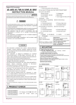
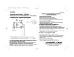
Doccol PID Temperature Controller
Model WS1500EBPM
User Manual
Version 1.0
Doccol Corporation
1235 E Pennsylvania Ave, Redlands, CA 92374
Tel: (888) 481-0842; Fax: (888) 893-5285
www.doccol.com
December 2011
A. Introduction
Thank you for purchasing the Doccol WS series temperature controller. We sincerely appreciate your
decision and believe that our machine will meet your expectations in product quality and experimental results.
We are delighted to provide this manual that will serve as guidance for operating this controller. In particular, we
would urge you to read through the safety warnings below, although this plug-and-play controller is very easy to
operate, your safety is paramount.
SAFETY WARNINGS
•
•
•
•
•
•
•
•
This controller was designed to be used only with selected heating devices that have limited power and
their own thermal cut off protection, such as a thermostat or thermal fuse in case of controller failure. Do
not use it with an untested device.
Do not place any objects on the top of controller surface that is used to vent excess heat during its
operation.
The maximum electric current this controller can handle is 15 ampere. For 120-volt AC in US and
Canada, this limits the heater power to1800 watts.
Always place the temperature sensor in the right position (the rodent rectum, or the surface of a
heating pad) when the controller is on and connected to heating device. Leaving the sensor
elsewhere will form an open loop operation; controller will assume the temperature is low and will provide
full power to the heater even if the heating pad is already over-heated.
The power cord provided with controller is specially designed for high power applications. Do not replace
it with regular computer power cord.
This controller is designed to control devices recommended by Doccol Corporation only. Using it to
control a not recommended device can be dangerous and cause fire. Doccol Corporation is not liable for
damages caused by misuse of the controller.
If an abnormal display or noise is observed, turn the controller off, unplug the power cord and contact the
manufacturer before using it again.
Clean the controller only when it is cool and unplugged.
B. Specifications
Input voltage:
Output voltage:
Maximum Current:
Fuse Size:
Control Action:
Control Mode
Output switching device:
Sensor type:
Sensor tip dimensions:
Sensor cable length,
Alarm:
Timer Range:
Temperature resolution:
Temperature display range:
Temperature accuracy:
Dimension:
Weight:
Warranty:
100 to 240 VAC 50 /60 Hz
Same as the input.
15A.
15A Fast blow.
Heating (reversed action) or cooling (direct action)
PID, PI, PD P or On/off
Built-in optically isolated solid state relay with zero voltage crossing witching.
Pt100 RTD sensor
Beaded head diameter 3 mm, shaft diameter 1.5 mm, shaft length 3 cm.
4.92 ft (1.5 m)
High limit alarm and Open loop alarm with LED and buzzer.
1 to 9999 minutes for each step. 6 steps total.
0.1 °C or 0.1 °F
-50.0 to 200.0 °C or -58.0 to 392.0 ° F
0.1°C or 0.2 °F for 0-85 °C (32.0 to 185.0 ° F)
6x3x7 inch (155 x80x180 mm) W x H x D.
3.2 lb (1.5 kg)
1 year for controller and sensor
Doccol Corporation, 1235 E Pennsylvania Ave, Redlands, CA 92374, Tel: (888) 481-0842; Fax: (888) 893-5285, www.doccol.com
-1-
Doccol PID Temperature Controller
Model WS1500EBPM
C. Operating Instruction
1. Description of the controller.
Figure 1. Front (left) and back (right) Panels
(1) Parameter Window (LED) - displays temperature values and controller's system parameters.
(2) Output status indicator - In normal mode, this LED indicates the heater status. When it is on (lit), the
heater is powered. When it is off, the heater power is off. When it is flashing, it means the heater is on and off
intermittently to reduce the power output.
(3) “SET” Key – press to show current temperature settings, get into parameters setting mode and
confirming various actions taken.
(4) “+” Key – press to increase displayed value.
(5) “_” Key – press to decrease displayed value.
(6) “Time” Key – press to change the Parameter Window’s display between current timer and temperature
values.
(7) Alarm indicator - Lit when the alarm is on.
(8) Timer status indicator - In normal mode, when “(8)” is on and “(9)” is flashing, LED shows the time
passed since it’s powered on.
(9) Mode indicator, the small “dot” – if it is lit and flashing, the value displayed in the Parameter Window is
time, else it is temperature. When it is flashing and “(8)” stays on, “(1)” is the time that has elapsed since it’s
powered on. When it is flashing “(8)” is off, the controller is in the parameter setting mode. “(1)” is the value
can be changed by using (4) and (5) key.
2. Connecting the controller
The connection of controller should be done in the following steps.
1) Plug the temperature sensor to the back of the controller.
2) Plug the power cord to the power outlet on the wall.
3) Turn on the controller to make sure the controller powers up properly. The temperature display is in the
range expected. Then, turn off the controller.
4) Plug the heater to the back of the controller. If the heater has a switch, put it in the off position. Put the
sensor inside the container to be controlled.
5) Turn on the controller.
6) Turn on the heating device.
Figure 2. Maneuvers to install (left) and remove (right) the sensor.
Doccol Corporation, 1235 E Pennsylvania Ave, Redlands, CA 92374, Tel: (888) 481-0842; Fax: (888) 893-5285, www.doccol.com
-2-
Doccol PID Temperature Controller
Model WS1500EBPM
Remark The connector of sensor contains a slot for correct pin connection. It also has a spring lock to
prevent disconnect by accidentally pulling on the cable. Figure 2, below, shows how to install and remove the
sensor.
3. Programming the temperature profile.
A total of 6 steps can be programmed for this controller. Each step
contains the temperature (C0X) and time duration (T0X) setting.
They are represented by the symbol C0X and T0X, where “X” is the
step number (e.g. Step 4 temperature is represented by C04 and
step 4 time is represented by T04). The character, “T”, is displayed
as the symbol, “ ”. Time is defined as the duration between the last
step and the next step. The time unit is in minutes with 1 minute
resolution. If your experiment only needs one step, you can program
the time of the rest of the steps to zero.
To program the temperature profile, press SET key once. The
display will show “C01” for one second and then display the
temperature setting value for step 1. Use “+” and “-” keys to change
the setting. When finished, press the SET again to confirm the
change. The display will show “T01” for a second and then change
to the time setting value for step 1. Use “+” and “-” keys to change
the setting. When finished, press the SET again to confirm the
change. The display will go the step 2 setting. Figure 3 (right) shows
the flow chart for this programming procedure.
The temperature setting will not be changed if SET is not pressed
(confirmed). After programming the necessary steps, you can finish
programming by pressing the SET repeatedly until it passed T06
and display the current temperature. You can also leave the
controller alone. The display will return to the normal display mode if
no key is pressed within 15 seconds.
The initial program setting (table 1)for the controller is for one step
heating. The temperature profile is programmed to target at 37.5 °C
for 9999 minutes.
4. Checking the current step and display the time
This is done by pressing the Time Key “(6)” once. The display will
show T0X for one second before it displays the time it has been on
that step. e.g., it will display t03 for a second, if the controller is in step
3 of the process. When “(8)” is on (lit) and “(9)” is flashing at the same
time, LED is in timer mode and shows the actual time passed since
the controller was in the current step. Please note that this is not the
total time since the controller is powered up. Press Time key again
will switch the display to the current temperature. Both “(8)” and “(9)”
will be off.
D. Performance Configuration
SET
080
4 sec
c 01
120
SET
SET
c 01
015
SET
SET
c 02
140
SET
SET
c 02
025
SET
SET
c 03
175
SET
SET
010
c 03
SET
SET
000
c 06
SET
SET
Figure 3. Temperature profile
programming flow chart
Table 1. Initial temperature profile setting
Step #
Temp (C)
Step #
Time (min)
C01
37.5.0
T01
9999
C02
0
T02
0
C03
0
T03
0
C04
0
T04
0
C05
0
T05
0
C06
0
T06
0
This controller is shipped with parameters set for in vivo rodent
surgery using 50W AC heating pad for maintaining rectal temperature set at 37.5 °C. You may need to change
these parameter values if you use it on other animal strains, or connect to different heating device.
1. Auto-Tune
The controller's most powerful feature is its ability to regulate virtually any heater with stable temperature control.
For stable temperature control the controller requires two things; (1) the controller must be set to the correct
power level (see next section) and, (2) that it must be tuned to the heater being used. Tuning is the process that
matches the control characteristics of the controller to the heating characteristics of the heater. The controller is
said to be tuned to the heater when its memory is programmed with values telling it how fast the heater warms up,
cools off, and how efficiently it transfers heat. Describing how fast the heater heats when electricity is turned on
and how fast it begins to cool when it's turned off. These time constants are called the tuning parameters.
Every type of heater has its own unique set of tuning parameters. For the controller to heat with stability, it must
have been programmed with the tuning parameters for the heater to be used.
2. Use auto-tune function to optimize controller performance settings
The controller is pre-tuned to work with our heating pad. You may use the auto-tuning function to let the controller
to determine the PID parameters for other heaters automatically. Auto-tuning function (it’s often known as
self-tuning) can automatically optimize the PID parameters for your chosen heating system. The auto-tuning
function will heat up your heater then let it cool down. It will repeat this heat/cool cycle several times. Based on
Doccol Corporation, 1235 E Pennsylvania Ave, Redlands, CA 92374, Tel: (888) 481-0842; Fax: (888) 893-5285, www.doccol.com
-3-
Doccol PID Temperature Controller
Model WS1500EBPM
the response time of the whole heating system, the controller will calculate and set the PID parameters for your
heater.
Before using the auto-tune function, you must set the heating
equipment up in the exact configuration it should be used. If the
heater has its own thermostat or power control, turn both as high
as they’ll go. Set the controller to the appropriate power level (see
next Section). Turn the controller and heater on, and then enter the
desired taarget temperature close to your normal use temperature.
To activate auto-tuning, just enter code 166 to get into the PID
setting menu. Set AΓ to 1 then exit the menu (see Figure 4). The
display will start to flash alternately between AΓ and current
temperature, which indicates auto-tuning is in progress. When the
display stops flashing, the auto-tuning is finished. Now, the newly
calculated PID parameters are set and are used for the system.
The new parameters will store in the memory even the power is off.
*Important: You should always write down your old PID
parameters, before letting the controller to perform
auto-tuning. The P, I, and D parameters have been pre-set to
45, 200, and 250, respectively. This way if something goes wrong,
you can always go back to your old PID parameters. Basically, you
must setup your heating system close to your actual heating
environment.
Figure 4. Code 166 parameter setup
The duration of auto-tuning depends on how fast the system is
responding to the heating and cooling cycle. If the temperature of the heater takes a long time to drop when
heater is off, the auto-tuning could be a very long tuning process. This is especially true with a well-insulated
heater. The auto-tuning should be able to tune most of your chosen with fairly good result.
3. Manual input of PID parameters.
The controller parameters are divided into two groups. The first group of parameters is related to the control
performance. They need to be adjusted based on the system to be controlled. If you have tried auto-tune and the
parameters we provided but feel the performance is not ideal, the following sections discuss the definition of
these parameters and how to change them.
3.1 Details about each parameter
• LCK. Parameter lock. This function is used to prevent user to change the critical parameters by accident.
User has to enter the code 166 to access the parameter setting menu (Figure 4).
• P. Proportional band. It is in 0.1 degree unit. This parameter control the output of the controller based on
the difference between the measured and set temperature. Larger the P number means the weaker the
action (lower gain). When the sensor temperature is 10 degrees below the proportional band (10 degrees
below the setting), the controller will have 100% output. When the temperature is 5 degree below the set
point, the output is 50%. When the temperature is equal to the setting, the controller will have 0% output
(assuming integral and derivative functions are turned off). This constant also affects both integral and
derivative action. Smaller P values will make the both integral and derivative action stronger. Please note
the value of the P is temperature unit sensitive. If you found an optimized P value when operating the
controller in Celsius, you need to multiply the P by 1.8 when changing the temperature unit to Fahrenheit.
• I. Integral time. The unit is in second. This parameter controls the output of controller based on the
difference between the measured and set temperature integrated with time. Integral action is used to
eliminate temperature offset. Larger number means slower action. When temperature fluctuates
regularly (system oscillating), increase the integral time. Decrease it if the controller is taking too long to
eliminate the temperature offset. When I=0, the system becomes a PD controller.
• d. Derivative time. The unit is in second. Derivative action contributes the output power based on the rate
of temperature change. Derivative action can be used to minimize the temperature overshoot by
responding its rate of change. The larger the number is, the faster the action will be. The derivative action
change the controller output based on the rate of change rather than the net amount of change. This will
allow the controller to act sooner. It will
turn the heater to full power before the
Table 2. Initial settings under code 166
temperature drops too much.
Symbol Description
Range
Initial
• AT: auto-tune. See above auto-tune
P
Proportional
band
(in
0.1
degree)
0-600
45
section.
I
Integral
constant
(second)
0-900
200
• T, cycle rate. The unit is in second. This
unit determines how long for the controller
d
Derivative constant (second)
0-300
250
to calculate each action. This parameter
AT
Auto-tune
0=off 1=on 0
should remain at 2 second for almost all
applications.
T
Cycle rate (second)
1-100
2
Doccol Corporation, 1235 E Pennsylvania Ave, Redlands, CA 92374, Tel: (888) 481-0842; Fax: (888) 893-5285, www.doccol.com
-4-
Doccol PID Temperature Controller
Model WS1500EBPM
3.2 Setting parameter values
• Press and hold SET key for 4 seconds until LED display “LCK”, then release the SET key. The display
will show “0”. To get into parameters setting mode, you need to key in the pass code. Use “+” and “-“keys
to adjust the display to 166 (which is the pass code) and press SET.
• The LED will show “P” for a second and then its P setting value, Use “+” and “-“ keys to change the
setting. When finished, press the SET again to confirm the change.
• The display will show the “I “ for a second and its I setting value next, use the same “P” setting procedure
to set the I value. When finished, press the SET again to confirm the change.
• The display will show the “d” for a second and its value next. Use the same “P” setting procedure to set
the d value. When finished, press the SET again to confirm the change.
• The next setting is AΓ, the auto-tune. Use “+” to set the value to 1 and press SET will activate the
auto-tune.
• The next setting is the “t” setting, use “-” and “+” to set the cycle time value. This value should remain 2
for most application.
• After change the PID parameter, the controller needs to be turned off and on again for the best result.
E. Other system parameters
The second group is about the system configuration and set up. Once they are set, they normally do not need to
be changed. This group of parameters can be accessed by input code 155. If you don’t want your system be
altered by other person, do not let other people know this code. Table 3 shows the list of the parameters, their
range and initial set value when left the factory.
Details about each parameter.
• SC, calibration offset. The parameter is used to make the input offset to compensate the error produced
by sensor. Each unit is 0.1 degree. e.g. if the temperature displays 2.0 °C in ice water mixture, set
SC=-2.0 will make the display to shown 0.0 degree.
• AL, Alarm temperature in degree. When the temperature passes the alarm set value, the alarm LED and
buzzer will be turned on. When temperature drops to that value, the LED and buzzer will be turned off.
The alarm is for high limit alarm only. It will not shut off the out.
• FA. Alarm buzzer control. When FA=1, the buzzer will be on when alarm LED is lit. When the FA=0,
the buzzer will not be turned on at the alarm temperature.
• oAL. Open loop alarm. This parameter is for detecting an open loop in the control system. e.g. if the
sensor was forgotten to be inserted in the oven, or the sensor is defective, or the heater is defective.
When enabled (oAL=1), it will shut off the output if the temperature increased less than 3 °C (5 °F) after
the controller is powered up for 5 minutes. The alarm buzzer will be turned on at the same time. The
display will flashing OPEN (oPEn).
• Hy. Hysteresis band (or dead band). This parameter is used for on/off control only. In the on/off heating
mode, the heater will turned off when T = SV, and turned on again when T<SV-Hy. e.g. If SV=100 °C.
Hy=3.0 °C, the heater will heat until temperature reaches 100.0C. It will be turned on again when
temperature drops below 97.0 °C. For the cooling mode, the compressor will be turned off when T=SV. It
will be on again when T>SV+Hy.
• CooL. When Cool=0, the controller is set for heating control (reverse action). When Cool=1, the controller
is set for cooling control (direct action).
• Out, Output power reduction. It is expressed as a percentage value. This function will allow you to control
the maximum output power delivered by the heater. For example, if you set Out=50 and your heater is
1000 watts, the output will use 50% of the 1000 watts as the full output. It thinks the 1000W heater as a
500W heater. When the PID algorithm determines 50% output value, the actual power output will be 250
watts.
• C-F, Display unit setting. You can set the display either Celsius or Fahrenheit.
Table 3. List of control parameters and the initial settings under code 155
Symbol
SC
AL
Description
Offset (degree)
Alarm Setting
FA
OAL
Hy
COOL
Out
C-F
Alarm buzzer
Open loop alarm
Hysteresis band
Control mode (heating or cooling)
Output power reduction (%)
Temperature unit
Range
-20.0 ~ +20.0
-58.0 ~ +392.0°F
-50.0 ~ +200.0°C
0=off 1=on
0=off 1=on
0 ~ 100
0=heat 1=cool
1-100
°C or °F
Initial
0~0.3
45
0
0
3
0
100
°C
Doccol Corporation, 1235 E Pennsylvania Ave, Redlands, CA 92374, Tel: (888) 481-0842; Fax: (888) 893-5285, www.doccol.com
-5-
Doccol PID Temperature Controller
Setting parameter values
This group of parameters is accessed by input
code 155. Figure 5 is the flow chart that shows
how they can be changed.
Press and hold SET key for 4 seconds until
Parameter Window displayed “LCK”. Release the
SET. The display will show “0”. Use “+” and “-”
keys to adjust the display to 155 (another pass
code) and press SET.
Setting the calibration offset. The parameter
window will first show “SC “for a second and then
its value, Use “+” and “-” keys to change the
setting. When finished, press the SET again to
confirm the change. For example, if the
temperature is 1 C too high during calibration then
use “-” to set the value to -1 to offset value.
Setting the output reduction. The parameter
window will first show “OUt “for a second and then
its value, Use “+” and “-“ keys to change OUt
value to your desired limit value and press SET.
Setting Celsius (C) or Fahrenheit (F). When
SET is pressed, the display will show “C- F” and
then its value of either “C” or “F”. Press “-” for C or
“+” for F.
The setting for AL, FA, oAL, Hy, Cool and TK are
similar as the rest of parameters.
Model WS1500EBPM
SET
30
3 sec
SET
LC8
155
sc
0
SET
SET
al
250
SET
SET
0
fa
SET
SET
o AL
0
SET
SET
hy
3
SET
SET
Co o l
0
SET
SET
00t
100
SET
SET
C-F
aF
SET
SET
Figure 5. Code 155 Parameter setup flow chart
F. Warranty
Doccol Corporation warrants this controller to be free from defects in materials and workmanship for a period of
one (1) year from the date of the original purchase when the device is utilized under normal condition. The sensor
of the controller is warranted for 90 days. This warranty is subject to the following conditions:
If the appliance is found to be defective in material or workmanship by Doccol Corporation, we will repair or
replace it free of charge. A dated proof of purchase may be required.
Doccol Corporation’s liability is limited solely to the cost of the repair or replacement of the unit at our discretion.
This warranty does not cover normal wear of parts and does not apply to any unit that has been tampered with or
used for commercial purposes. This limited warranty does not cover damage caused by misuse, abuse, negligent
handling or damage due to faulty packaging or mishandling in transit. This warranty does not cover damage or
defects caused by or resulting from damages from shipping or repairs, service or alterations to the product or any
of its parts which have been performed by a repairperson or facility not authorized by Doccol Corporation.
This warranty is available to the original purchaser of the unit and excludes all other legal and/or conventional
warranties. The responsibility of Doccol Corporation, if any, is limited to the specific obligations expressly
assumed by it under the terms of the limited warranty. In no event is Doccol Corporation liable for incidental or
consequential damages of any nature whatsoever. Some states/provinces do not permit the exclusion or
limitation of incidental or consequential damages and therefore the above may not apply to you.
This warranty gives you specific legal rights and you may also have other rights that vary from state to state or
province to province.
*Important: Carefully pack item to avoid damage in shipping. Be sure to include proof of purchase date and to
attach a tag to item before packing with your name, complete address and phone number with a note giving
purchase information, model number and what you believe is the problem with the item. We recommend you
insure the package (as damage in shipping is not covered by your warranty). Mark the outside of your package
“ATTENTION CUSTOMER SERVICE”. We are constantly striving to improve our products and therefore the
specifications contained herein are subject to change without notice.
Doccol Corporation, 1235 E Pennsylvania Ave, Redlands, CA 92374, Tel: (888) 481-0842; Fax: (888) 893-5285, www.doccol.com
-6-