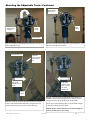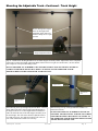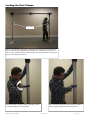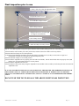
1
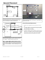
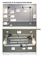
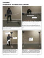
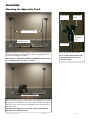
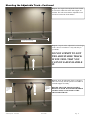
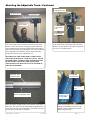
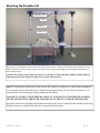
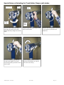
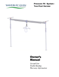
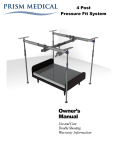
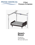
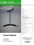
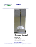
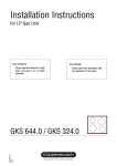
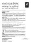
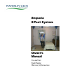
Sequoia
2 Post System
●
Owner’s
Manual
Use and Care
Fault Finding
Warranty Information
Table of Contents
Sequoia 2 Post System
●
Introduction........................................................................................... 3
Overview ................................................................................................ 3
Placement of the Sequoia ................................................................ 4
Components of system ...................................................................... 5
Component list ..................................................................................... 6
Specifications....................................................................................... 6
Cautions ................................................................................................. 7
Assembly
Assembling the Side Supports ................................................. 8
Mounting the Adjustable Track .............................................11
Locking the Post Clamps........................................... 16
Final Inspection prior to use ..................................................17
Mounting the Portable Lift..............................................................18
Dismantling the Sequoia .................................................................19
Fault finding ........................................................................................20
General inspection and maintenance.........................................21
Service record history .....................................................................22
Warranty ...............................................................................................26
753460 - Sequoia - User Guide
Rev: 4/12/07
Page: 2
CAUTION: DO NOT ATTEMPT TO USE THIS EQUIPMENT
WITHOUT FIRST UNDERSTANDING THE CONTENTS OF
THIS MANUAL.
Introduction
Before using this equipment, and to ensure the safe operation of your Sequoia 2 Post system (Sequoia), carefully read this entire manual, especially the section on “Cautions”. The Sequoia 2 Post system is designed
to be used in conjunction with Waverley Glen Systems Ltd. portable lift units, accessories and slings. Please
refer to any user guides supplied with these components and reference them while reviewing this manual.
●
●
Should any questions arise from reviewing this manual contact your local authorised Waverley Glen Systems
Ltd. dealer. Failure to comply with warnings in this manual may result in injury to the operator, or the individual being lifted/transferred. Damage to the lift and/or related components may occur. Be sure that the contents
of this manual are completely understood prior to using this piece of equipment.
Store this manual with the documents included with the lift system and sling (s). Contents of this manual are
subject to change without prior written notice.
Overview of the Sequoia 2 Post System
●
The Sequoia 2 Post system is a lifting aid used by health care professionals and those providing care in the
home to lift, position and transfer clients or a disabled family member. The Sequoia 2 Post system is part of
what is termed overhead lift technology which takes advantage of lifting from above and not from below or the
side. The Sequoia 2 Post system makes it possible to move mobility impaired individuals with minimal strain
or risk to the caregiver, while providing complete safety, dignity and comfort for the client or family member.
●
●
●
The Sequoia 2 Post system is designed to work with a Waverley Glen portable lift system such as the
transportable II. Use of other portable lift units with this system may be possible. However, please contact
your local authorised Waverley Glen Systems Ltd dealers in order to obtain approval before use.
●
TM
The Sequoia 2 Post system is a floor based free standing system that can be used to lift and transfer individuals
from a bed, chair or similar fixture. It is adjustable in both length and height and thus can be assembled to suit
a wide range of applications. The Sequoia 2 Post system is easy to assemble and can be completed by just one
person in a short period of time. Additionally, no tools are required. It is also light in weight and once dismantled, can be moved to another location such as a hotel or cottage.
●
●
Additionally the Sequoia 2 Post system is truly free standing. The two side supports do not require a secure
ceiling in order to be pressure fitted like other systems, because they simply rest on the floor.
●
Moreover, the Sequoia 2 Post system has independently adjustable feet. This means that they can be individually height adjusted. This is typical of transferring from a sunken living room to a hallway or kitchen.
●
Please review the following pages that outline the parts included with your package. Should you have any
questions about this product or its use contact your local authorised dealer.
753460 - Sequoia - User Guide
Rev: 4/12/07
Page: 3
General Placement
Adjustable Track
Adjustable Track
Trolley
Trolley
Portable
Lift
Side Support
Assembly
Side Support
Assembly
Bed
Bed
Foot
Foot
Drawing showing Front View and the general placement of a
bed in relationship to the Sequoia. Notice that there is still
room for a wheelchair to be placed beside the bed.
Photo showing the general placement of a bed in relationship to
the Sequoia. Notice that there is still room for a wheelchair to be
placed beside the bed.
General Placement Requirements
1)
39” - 45” (1000mm - 1145mm)
from head of bed
2)
3)
4)
Bed
Adjustable Track
Foot
The Bases of the Sequoia must always be placed on a level surface.
Do not place the Bases on surfaces that will cause them to wobble
or be unstable. Make sure the surfaces are free of any obstacles that
may cause the Bases to be unstable.
Never place the Bases on wet surfaces.
Assemble the Sequoia so that the Adjustable Track is directly over
the location where the transfer will occur. For beds this is generally
between 39” - 45” (1000mm - 1145mm) from the head of the bed.
For wheelchairs, living room chairs, recliner chairs and similar
furniture this is directly above the middle (center) of the seat.
Drawing showing Top View of Sequoia system. Assemble the
Sequoia so that the Adjustable Track is located between 39” 45” (1000mm - 1145mm) from the head of the bed.
DO NOT GO OUTSIDE OF THIS RANGE OF PLACEMENT OTHERWISE INJURY MAY OCCUR TO THE
OPERATOR OF THE LIFT AND/OR THE INDIVIDUAL
BEING TRANSFERRED, AND/OR THE SEQUOIA OR
LIFT.
753460 - Sequoia - User Guide
Rev: 4/12/07
Page: 4
Components of the Sequoia 2 Post System
●
Track
Holder,
Lid &
Clamp
Top Post
Section
Post
Clamp
Bottom Post
Section
Adjustable
Track
Trolley
Side
Support
Assembly
Height Indicator
& Ruler
Foot
Clamp
Foot
Figure 1A - Fully Assembled the Sequoia 2 Post system on a normal floor.
●
Top Post
Sections
Foot
Adjustable
Track
Foot
Trolley
Bottom Post
Sections
Figure 1B - Unassembled Sequoia 2 Post system with individual pieces before assembly.
●
753460 - Sequoia - User Guide
Rev: 4/12/07
Page: 5
Component List
The following components are included with your new Sequoia 2 Post system:
●
Description
Quantity
Foot
2
Bottom Post Section
2
Top Post Section
2
Adjustable Track
1
Owners Manual
1
Warranty Card
1
Specifications of the Sequoia 2 Post System
●
•
•
•
•
•
•
•
•
•
•
•
•
•
•
High-strength lightweight Aluminum
Portable or semi-permanent installation
Eliminates the mounting of a connection system in the ceiling
One person set up
Quick attachment with secure fixings
Addresses a number of different bedroom & bathroom situations
Weight capacity 400lb
Adjustable in height
Adjustable in length
Built-in easy-slide trolley
Adjusts to multi-level floors. (individuals can be transferred from a sunken living room to a hallway)
Can be used with any portable lift system that attaches to a standard trolley eyelet (Dealer Approved)
Track leveling indicators on posts
Two (2) year warranty
Minimum - Maximum Dimensions
Model Table for the Sequoia 2 Post System
●
753460 - Sequoia - User Guide
Code
Description
341200
Sequoia including side support feet, track and trolley
341300
Sequoia carrying bag
Rev: 4/12/07
Page: 6
Cautions
●
The Sequoia must be assembled prior to use. Should you have any questions during assembly contact
your local authorised dealer.
●
Under no circumstance should the track, lift and sling (s) or entire system be put in control of a person
who has not been properly trained in the use and care of this equipment. Failure to adhere to this
warning may result in serious injury to the operator, and/or the individual being lifted/transferred.
●
The Sequoia and associated track and sling (s) are not toys. Do not use them for unsafe
practices. Do not allow children to play with the this equipment or any of its components.
●
form
The manufacturer's warranty is void if persons unauthorised by Waverley Glen Systems Ltd. perwork on the Sequoia.
●
In facilities where more than one operator will be responsible for using the Sequoia associated lift and
sling (s) it is imperative that all such members be trained in its’ proper use. A training program
should be established by the facility to acquaint new operators with this equipment.
●
Never expose the Sequoia directly to water. Warranty does not cover any misuse or abuse of the lift
system.
●
To maintain optimum function, the Sequoiashould be inspected and maintained on a regular basis.
See the section titled “General Inspection and Maintenance”.
●
Any accessories used with the Sequoia including lift and sling (s), should be checked to ensure that
they are in good working order. Check for signs of wear or fraying prior to use. Report any unusual
wear or damage immediately to your local authorised dealer.
●
The Sequoia and associated lift, and sling (s) are intended only for lifting and transferring of a person.
Waverley Glen Systems Ltd. will not be responsible for any damage caused by the misuse, neglect
or purposeful destruction of the lift and/or its’ associated components.
●
Do not in any circumstance exceed the maximum load for this piece of equipment. Refer to the
“Specifications” section of this manual.
●
The installation of the Sequoia, lift, accessories, and sling are certified to a maximum load. Do not
exceed the maximum rated load of any of the components.
●
Ensure that a clear space is maintained around the Sequoia. Remove all furniture and other obstacles
out of the way before performing a transfer.
●
The Sequoia has been designed to lift vertically at its maximum load and at maximum height. Do not
attempt to lift an individual at an angle to the track.
753460 - Sequoia - User Guide
Rev: 4/12/07
Page: 7
Assembly
Caution: Before using the Sequoia, the feet, sides, latches and track must be visually
checked to ensure that they are correctly secured, and for any unusual wear and tear.
Should anything look unusual contact your local dealer prior to use.
Failure to comply with this caution could result in serious injury to the operator, the individual being lifted and/or damage to the Sequoia and/or portable lift unit.
Assembling the Side Supports
Foot Clamp in
open position
Foot
Step 1 - Place the each Foot on a
flat surface at about their final
location. (e.g. one on either side
of a bed or chair). Swing open
the Foot Clamp Arm. This will
allow the Lower Post Section to
be inserted into the opening.
Foot
Step 2 - With the Foot Clamp
Arm swung in a open position,
place one of the Lower Post Section pieces securely into the open
hole of a Base piece. Ensure that
it is pushed all the way in.
Step 3 - Lower Post Section
properly inserted into the Foot.
Step 5 - Lock the Foot to the
Lower Post Section by swinging
the Foot Clamp Arm completely
around.
Step 6 - Foot Clamp Arm
properly secured. DO NOT
PROCEED TO THE NEXT
STEP UNLESS THIS IS
COMLETED.
Holding Pin
should pop
through this hole
Step 4 - Be sure that the Lower
Post Section Holding Pin pops
into the small hole in the Foot.
This ensure that the pieces are
locked together.
753460 - Sequoia - User Guide
Rev: 4/12/07
Page: 8
Assembly
Assembling the Side Supports...Continued
Height Indicator
Height Indicator
Ruler
Height Adjustment
Wheel
Step 7 - The Sequoia comes pre-set from the factory to be used
in a room with a standard 8 foot (2500mm) ceiling height. If
this needs to be changed it is most easily completed at this time
in the set-up.
Lay the Foot with the Lower Post Section that were just
connected together, onto the floor as shown.
Use the Height Adjustment Wheel to raise or lower the Height
Indicator to the desired height. The Height Indicator Ruler,
located on the side of the Lower Section Post should be used to
precisely measure the desired height.
Height Adjustment
Wheel
753460 - Sequoia - User Guide
Rev: 4/12/07
Page: 9
Assembly
Assembling the Side Support Poles...Continued
Height Indicator
Step 9 - Turn the Top Post Section so that the Track Holder is at
right angles (90 °) to the Foot. Slide the Top Post Section into
the opening of the Bottom Post Section until it cannot go in any
further. At this point it should rest on the Height Indicator.
Step 8 - Carefully lay the Bottom Post Section and Foot that
were previously secured together, onto their side, as shown.
Grasp the Top Post section.
Note: The Top Post Section will only go into the hole one way
because it is a ‘keyed’ connection. Do not force the Top Post
section into the Bottom Post Section. They should slide together
easily.
Track Holder
Assembly left in
open position
Post Clamp left
in open position.
Step 10 - Holding the end of the Top Post Section, tilt the entire assembly up so that it is standing upright as shown. Note the position of the
Track Holder. It must be at right angles (90 degrees) to the Base.
753460 - Sequoia - User Guide
Position Side
Support Assemblies the desired
width apart.
Step 11 - Proceed to set up the second Side Support Assembly by
following the steps 1 - 10. Carefully move both assemblies to
their final location. Be sure that the Track Holders are roughly
aligned together. This will make placement of the Adjustable
Track easier to accomplish.
Rev: 4/12/07
Page: 10
Assembly
Mounting the Adjustable Track
Track Holder
Lid
Track Holder
Latch
Side Support Assembly
Track Holder
AlignmentPeg
Adjustable Track
Track Holder
Step 12 - With the two (2) Side Support Assemblies in their upright position
and their Track Holders in an open position, place the Adjustable Track in
front of the Side Support Assemblies.
BE SURE THAT THE SIDE SUPPORT ASSEMBLIES ARE PLACED
IN A STABLE LEVEL FLOOR LOCATION.
Photo showing open Track Holder.
DO NOT PROCEED UNLESS THE
TRACK HOLDER LID IS IN AN
OPEN POSITION.
Step 13 - Holding the two (2) sliding sections of the Adjustable Track, slide
the sections closer together, or, further apart. When completed, the length of
the Adjustable Track should be at least the width of the entire Side Support
Assemblies. This will ensure that the Adjustable Track will fit into each of
the Track Holders.
NEVER FORCE THE LENGTH OF THE ADJUSTABLE TRACK
BEYOND ITS MAXIMUM LIMIT.
753460 - Sequoia - User Guide
Rev: 4/12/07
Page: 11
Mounting the Adjustable Track...Continued
Step 14 - The length of the Adjustable Track should
be at least the width of the entire Side Support Assemblies. This will ensure that the Adjustable Track
will fit into each of the Track Holders.
Adjustable Track at desired length
Step 15 - Grasp the entire Adjustable Track and begin
to lift it. Be sure to balance it evenly and safely in
your hands.
DO NOT ATEMPT TO LIFT
THE ADJUSTABLE TRACK
IF YOU FEEL THAT YOU
CANNOT SAFELY HANDLE
IT.
Step 16 - Raise the Adjustable Track to a height so
that it will fit easily into the opened Track Holder on
each Side Support Assembly.
Place end of
Adjustable Track
in the full length
of the Track
Holder.
753460 - Sequoia - User Guide
Place end of
Adjustable Track
in the full length
of the Track
Holder.
Rev: 4/12/07
BE SURE THAT THE TRACK IS SAFELY
RESTING IN EACH TRACK HOLDER PRIOR
TO RELEASING YOUR GRASP OF THE
ADJUSTABLE TRACK.
Page: 12
Mounting the Adjustable Track...Continued
Adjustable Track
Adjustable Track
Track Holder
Track Holder
Lid
Track
Clamp
Track Holder
Step 17 - Ensure that the Adjustable Track extends to the end of
each Track Holder and rests in the slotted section of the Track
Holder. It can be moved to the end by grasping the Adjustable
Track and Side Support Assembly, and then moving the Adjustable Track to the end of the Track Holder. The hole in the bottom
of the Adjustable Track should fit into the Track Holder Peg
located on the bottom of the Adjustable Track.
Photo showing the Adjustable Track properly seated
in the Track Holder, and with the Lid of the Track
Holder in an open position. The Track Clamp at this
time is not in a locked position.
BE SURE THAT THE OTHER END OF THE ADJUSTABLE TRACK DOES NOT COME OUT OF ITS’ TRACK
HOLDER WHILE COMPLETEING THIS PROCEDURE.
IF NECESSARY, LENGTHEN THE ADJUSTABLE
TRACK FIRST AND THEN MOVE IT TO THE END OF
THE TRACK HOLDER.
Adjustable Track
Alignment Hole
Track Holder
Alignment Peg
Track Holder
Lid
Bottom of Adjustable Track
Inside view of
Track Holder
Photo showing the Alignment Hole on the bottom of the Adjustable Track. This will fit into the Track Holder Alignment Peg to
secure the connection. The Track Holder Lid will not close properly unless this connection is completed.
753460 - Sequoia - User Guide
Rev: 4/12/07
Photo showing inside view of Track Holder
with the Track Holder Lid open. On the
bottom of the Track Holder is the Track
Holder Alignment Peg.
Page: 13
Mounting the Adjustable Track...Continued
Track Holder
Lid Closed
Track Holder
Lid Open
Track
Clamp
Track
Clamp
Track Holder
Step 18 - Grasp the Track Holder Lid and swing it over the top
of the Adjustable Track.
Track Holder Lid
Photo showing the Track Clamp Lid in a closed position. Complete this procedure for both Lids.
Catch the
Latch onto the
Track Holder
Lid
Pull Track
Holder Clamp
Back
Push Track
Holder Clamp
Back to Lock
the Track
Holder Lid
Track
Clamp
Step 19 - Grasp the Track Clamp and swing it back under the
bottom of the Track Holder sufficiently enough to allow the
Latch to take hold of the top of the Track Holder Lid.
Step 20 - Once the Latch has grasped the Track Holder Lid
swing the Track Holder Clamp back to its original position
snuggly up against the underside of the Track Holder.
Proceed to lock the remaining three (3) Track Holder Clamps
in the same fashion as just described.
Double check to ensure that all four (4) Track Clamps are
securely locked prior to proceeding.
753460 - Sequoia - User Guide
Rev: 4/12/07
Page: 14
Mounting the Adjustable Track...Continued - Track Height
Before making minor adjustments to the height of the
Adjustable Track make sure
the Post Clamps are in a open
position.
Height Adjustment Wheel
Step 21 - Double check the Height Indicator on each Side Support Assembly. Minor Adjustments can be completed
at this time by turning the Height Adjustment Wheel either to the left or right. (See detail below). Be sure that the
Post Clamps are in an open (unlocked) position.
DO NOT PROCEED ANY FURTHER UNTIL THE ADJUSTABLE TRACK IS LEVEL. FAILURE TO
COMPLY WITH THIS WARNING MAY RESULT IN INJURY TO THE OPERATOR AND/OR
INDIVIDAL BEING LIFTED AND/OR THE TS OR LIFT UNIT.
Height Indicator
Height Indicator
Ruler
Height Adjustment
Wheel
Photo showing close-up of Height Adjustment Wheel. Turn the
wheel either to the left or right to make small adjustments to
the height of the track. Use the Height Indicator and Ruler to
make sure that both sides of the Side Support Assembly are at
the same height. This will ensure that the Adjustable Track is
level and safe for use. For multi-level setting refer to the section of this manual titled “Multi-Level Set-Up”.
753460 - Sequoia - User Guide
Photo showing close-up of Height Indicator and Ruler on
Bottom Post Section.
DO NOT PROCEED ANY FURTHER UNTIL THE ADJUSTABLE TRACK IS LEVEL. FAILURE TO COMPLY
WITH THIS WARNING MAY RESULT IN INJURY TO
THE OPERATOR AND/OR INDIVIDAL BEING LIFTED
AND/OR THE TS OR LIFT UNIT.
Rev: 4/12/07
Page: 15
Locking the Post Clamps
Post Clamps
Step 22 - The final step to assembly is locking the Post Clamps. These are located at
the joint where the Top and Bottom Post Sections meet. Placing one hand on the Top
Post Section and one hand on the clamp, swing the Post Clamp around to lock the posts
together. (See detail photos below)
Photo showing the open Post Clamp, and proper position
to swing the clamp to a locked position.
753460 - Sequoia - User Guide
Photo showing the position of the locked Post Clamp. It
must fit snuggly against the Bottom Post Section.
Rev: 4/12/07
Page: 16
Final inspection prior to use
7) Trolley slide easily along the Adjustable Track
6) Adjustable Track is Level
5) Track Holder Clamps Locked
4) Post Clamps Locked
3) Height Indicators are at same height
for single level installations
2) Foot Clamps Locked
1) Entire assembly rests safely on floor
Step 23 - As a final step before using the Sequoia, check the entire assembly taking special note of the following:
1) Ensure that the entire assembly rests safely on the floor, and that it does not wobble or tilt in any fashion.
2) Ensure both Foot Clamps are in a locked position.
3) Check the Height Indicators and Rulers on both Side Support Assemblies to be sure they are the same for single level
installations. For Multi-level installations, skip this inspection point.
4) Ensure both Post Clamps are in a locked position.
5) Ensure that the Adjustable Track is properly placed in both Track Holders, that the Track Holder Lids are properly closed, and
that the four (4) Track Holder Clamps are securely locked.
6) Ensure that the Adjustable Track is level.
7) Ensure that the Trolley slides easily along the Adjustable Track, and that it does not slide by itself when placed at each end of the
Adjustable Track.
IF ANY OF THE ABOVE ITEMS DO NOT PASS INSPECTION, THEN REVIEW THE APPROPRIATE SECTION OF
THIS OWNER’S MANUAL AND RE-ADJUST THE ITEM AS NECESSARY. IF THERE IS ANY UNCERTAINTY
ABOUT ANY OF THESE POINTS OF INSPECTION, CONTACT YOUR LOCAL AUTHORISED DEALER IMMEDIATELY.
DO NOT USE THE TS UNLESS ALL THE ABOVE POINTS PASS INSPECTION.
753460 - Sequoia - User Guide
Rev: 4/12/07
Page: 17
Mounting the Portable Lift
Adjustable Track
Trolley
Lift Strap
Portable Lift
Step 24 - Prior to mounting the portable lift onto the trolley of the Sequoia, read the owners manual of the portable lift. Be sure
that the instructions on the use of the lift and any accessories, such a slings are thoroughly understood before attempting to use
them with the Sequoia.
FAILURE TO COMPLY WITH THIS MAY RESULT IN INJURY TO THE INDIVIDUAL BEING LIFTED AND/OR
THE CAREGIVER, OR DAMAGE TO THE LIFT AND/OR THE SEQUOIA.
Step 25 - Following the instructions for the portable lift, attach the carabeener, (or other similar attaching device) located at the end of the lift strap, to the hole of the Sequoia trolley. Be sure that the carabeener is securely attached to the trolley prior to proceeding with the transfer.
FAILURE TO COMPLY WITH THIS MAY RESULT IN INJURY TO THE INDIVIDUAL BEING
LIFTED AND/OR THE CAREGIVER, OR DAMAGE TO THE LIFT AND/OR THE SEQUOIA.
Proceed to transfer the individual in the manner described in the owners’ manual for the portable lift and sling.
When the transfer is completed the lift may be removed from the trolley.
753460 - Sequoia - User Guide
Rev: 4/12/07
Page: 18
Dismantling the Sequoia 2 Post System
●
Should it be necessary to dismantle the Sequoia, carefully follow the instructions below:
1) Remove any lifting device such as the portable lift from the trolley of the Sequoia.
2) Remove any slings or other equipment attached to or laying on top of the Sequoia.
3) Unlock the four (4) Track Holder Clamps. Note that the clamp may need to be manually lifted up slightly
so that it comes away from the lip of the Track Holder Lid. (Refer special notes on next page of this user
guide).
4) Open both Track Holder Lids.
5) Carefully lift and remove the Adjustable Track from the Track Holder and place it immediately on the
floor.
DO NOT ATTEMPT TO LIFT AND/OR REMOVE THE ADJUSTABLE TRACK
UNLESS YOU ARE CAPABLE OF LIFTING IT SAFELY. CONTACT YOUR
LOCAL AUTHORISED DEALER FOR ASSITANCE.
6) With the Adjustable Track resting on the floor, carefully slide both sections of the Adjustable Track together to its shortest position.
7) Set the Adjustable Track aside in a safe place until the rest of the Sequoia is dismantled.
8) Unlock both Post Clamps.
9) Lay each of the Side Support Assemblies safely on the floor for further dismantling.
10) Remove the Top Post Section from the Bottom Post Section.
11) Close the Track Holder Lids and lock them, and then set the Top Post Section aside in a safe place.
12) Unlock the Foot Clamps.
13) Remove the Bottom Post Section from the Foot.
14) Lock the Post Clamps and then set the Bottom Post Section aside in a safe place.
15) Move the Foot and all other pieces that have been dismantled to a safe storage area.
753460 - Sequoia - User Guide
Rev: 4/12/07
Page: 19
Special Notes on Unlocking the Track Holder Clamps and Latches
Track Holder Lid
Latch
Track
Clamp
Grasp the Track Clamp and swing it
back under the bottom of the Track
Holder sufficiently enough to loosen the
Latch.
Once the Latch is lifted up and away
from the Track Holder Lid it can be
released. Repeat this procedure for each
of the Latches.
753460 - Sequoia - User Guide
Latch
Track
Clamp
Grasp the edge of the Track Holder Lid as
shown with one hand.
With the other hand grasp the Latch and
lift it up and away from the Track
Holder Lid.
Track Clamp and Latch moved away
from the Track Holder Lid. The Lid
can now be moved away.
Rev: 4/12/07
Page: 20
Fault Finding
Should problems arise with the use of the Sequoia review the following chart. Find the fault and complete the
recommended solution. If the fault is not found and/or the solution does not correct the problem contact your
local authorised dealer for service immediately.
Fault
Recommended Solution
Foot Clamp Arm does not swing
and lock into position.
Check whether this Foot Clamp Arm is damaged. If so, then contact your local authorised
dealer immediately so that the Sequoia can be checked to ensure proper continued operation.
Post Clamp does not swing and lock Check whether this Post Clamp is damaged. If so, then contact your local authorised dealer
into position.
immediately so that the Sequoia can be checked to ensure proper continued operation.
The Bottom Post Section does not
fit into the opening of the Base.
Check to be sure that no obstacle is blocking the opening to the Base. Remove obstacle and
try again.
Check for damage to the opening in the Base or the end of the Bottom Post Section. If so,
then contact your local authorised dealer immediately so that the Sequoia can be checked to
ensure proper continued operation.
Check how the Bottom Post section is being inserted into the opening of the Base. Since the
connection is ‘keyed’, it will only go in one way. Rotate the Bottom Post Section so that the
‘keyed’ areas line up. Try to insert the Bottom Post section into the Base again. If this does
not correct the problem then contact your local authorised dealer immediately so that the lift
can be checked to ensure proper continued operation.
The Top Post Section does not fit
into the opening of the Bottom Post
Section.
Check to be sure that not obstacle is blocking the opening to the Bottom Post Section. Remove obstacle and try again.
Check for damage to the opening in the Bottom Post Section or the end of the Top Post Section. If so, then contact your local authorised dealer immediately so that the Sequoia can be
checked to ensure proper continued operation.
Check how the Top Post section is being inserted into the opening of the Bottom Post Section. Since the connection is ‘keyed’, it will only go in one way. Rotate the Top Post Section
so that the ‘keyed’ areas line up. Try to insert the Top Post section into the Bottom Post Section again. If this does not correct the problem then contact your local authorised dealer immediately so that the lift can be checked to ensure proper continued operation.
The Adjustable Track does to fit
into the Track Holder correctly.
Check for damage to the bottom of the Track Holder or bottom of Adjustable Track. If so,
then contact your local authorised dealer immediately so that the Sequoia can be checked to
ensure proper continued operation.
Check to be sure that the bottom of the Adjustable Track is in being placed in the Track
Holder. The bottom of the Adjustable Track has a slot in it that is ‘keyed’ the ridge on the
bottom of the Track Holder. Rotate the Adjustable Track and try again.
Near each end of the Adjustable Track is an Alignment Hole that is designed to fit into the
Alignment Peg of the Track Holder. Review this and try to place the end of the Adjustable
Track so that the correct alignment is attained.
If this does not correct the problem then contact your local authorised dealer immediately so
that the lift can be checked to ensure proper continued operation.
Trolley slides by itself when placed
at one end of the track.
The Adjustable Track is not level. Check the Height Indicator at each end. Be sure that they
are exactly the same (for single level installations). Adjust the height with the Height Adjustment Wheel so that they are the same. For multi-level installations use a level to check the
Adjustable Track. If is not level then adjust the height with the Height Adjustment Wheel
until the Adjustable Track is level.
The trolley does not move easily
along the Adjustable Track or gets
stuck.
Check the sides of the Adjustable Track for any obstacles or damage. Clear any obstacles
away that may interfere with the Trolley. If damage to the Adjustable Track or Trolley is observed, then contact your local authorised dealer immediately so that the lift can be checked
to ensure proper continued operation
753460 - Sequoia - User Guide
Rev: 4/12/07
Page: 21
General Inspection and Maintenance
A) Each Use - To be completed by User
Prior to each use, the Sequoia and associated lift, accessories and sling (s), must be visually inspected. Refer
to the lift, accessory and sling user guides for specific details regarding their inspection.
Should any of the these items below fail the inspection do not use the Sequoia
Contact your local authorised dealer for service.
Visually check for the following:
□
The Bases are on a stable, level surface and the Side Support Assemblies are secure.
□
The Foot Clamps are locked.
□
The Post Clamps are locked.
□
The Track Holder Lid is closed and the Track Holder latch is locked.
□
The Trolley moves easily along the track.
□
The Adjustment Track is placed in the correct location for transferring.
□
The portable lift has been inspected as outlined in it’s owners manual.
□
The sling (s) has been inspected as outlined in it’s owners manual.
753460 - Sequoia - User Guide
Rev: 4/12/07
Page: 22
Service Record History - Initial Information
•
•
•
•
Complete the following section on Purchase and Service Information as soon as this
equipment is installed.
Use the service record history to record to any completed service and repairs.
Ensure that the service record is signed and dated each time it is used.
Be sure to have this piece of equipment serviced on a regular basis as described in the
General Inspection and Maintenance Section
PURCHASE INFORMATION:
Sequoia 2 Post system
Serial#:________________________
Date of Purchase: _____________________
Date Installed: _________________
Product Name:
●
Purchased From: ___________________________________________________________
Address:
_______________________________________
City:
__________________________
Telephone No:
__________________________
Post Code: ____________________
Comments:
SERVICE INFORMATION:
Contact the following company for service:
Company:
___________________________________________________________
Address:
_______________________________________
City:
__________________________
Telephone No:
Post Code: _________________
__________________________
Comments:
753460 - Sequoia - User Guide
Rev: 4/12/07
Page: 23
Service Record History
Date: _______________________
Service Type: □ Periodic Inspection
Complete this section after each service, repair inspection and/
or maintenance. Photocopy additional pages as required.
Time: ________________________
□ Monthly Inspection
Completed By: _________________________
□ 6 Month Inspection □ Repair □ Yearly Inspection □ Other:_________
_____________________________
Printed Name
Signature
Company: _____________________________________________________________
Remarks & Action Taken:
Date: _______________________
Service Type: □ Periodic Inspection
Time: ________________________
□ Monthly Inspection
Completed By: _________________________
□ 6 Month Inspection □ Repair □ Yearly Inspection □ Other:_________
_____________________________
Printed Name
Signature
Company: _____________________________________________________________
Remarks & Action Taken:
753460 - Sequoia - User Guide
Rev: 4/12/07
Page: 24
Service Record History
Date: _______________________
Service Type: □ Periodic Inspection
Complete this section after each service, repair inspection and/
or maintenance. Photocopy additional pages as required.
Time: ________________________
□ Monthly Inspection
Completed By: _________________________
□ 6 Month Inspection □ Repair □ Yearly Inspection □ Other:_________
_____________________________
Printed Name
Signature
Company: _____________________________________________________________
Remarks & Action Taken:
Date: _______________________
Service Type: □ Periodic Inspection
Time: ________________________
□ Monthly Inspection
Completed By: _________________________
□ 6 Month Inspection □ Repair □ Yearly Inspection □ Other:_________
_____________________________
Printed Name
Signature
Company: _____________________________________________________________
Remarks & Action Taken:
Date: _______________________
Service Type: □ Periodic Inspection
Time: ________________________
□ Monthly Inspection
Completed By: _________________________
□ 6 Month Inspection □ Repair □ Yearly Inspection □ Other:_________
_____________________________
Printed Name
Signature
Company: _____________________________________________________________
Remarks & Action Taken:
Date: _______________________
Service Type: □ Periodic Inspection
Time: ________________________
□ Monthly Inspection
Completed By: _________________________
□ 6 Month Inspection □ Repair □ Yearly Inspection □ Other:_________
_____________________________
Printed Name
Signature
Company: _____________________________________________________________
Remarks & Action Taken:
Date: _______________________
Service Type: □ Periodic Inspection
Time: ________________________
□ Monthly Inspection
Completed By: _________________________
□ 6 Month Inspection □ Repair □ Yearly Inspection □ Other:_________
_____________________________
Printed Name
Signature
Company: _____________________________________________________________
Remarks & Action Taken:
Date: _______________________
Service Type: □ Periodic Inspection
Time: ________________________
□ Monthly Inspection
Completed By: _________________________
□ 6 Month Inspection □ Repair □ Yearly Inspection □ Other:_________
_____________________________
Printed Name
Signature
Company: _____________________________________________________________
Remarks & Action Taken:
753460 - Sequoia - User Guide
Rev: 4/12/07
Page: 25
Service Record History
Date: _______________________
Service Type: □ Periodic Inspection
Complete this section after each service, repair inspection and/
or maintenance. Photocopy additional pages as required.
Time: ________________________
□ Monthly Inspection
Completed By: _________________________
□ 6 Month Inspection □ Repair □ Yearly Inspection □ Other:_________
_____________________________
Printed Name
Signature
Company: _____________________________________________________________
Remarks & Action Taken:
Date: _______________________
Service Type: □ Periodic Inspection
Time: ________________________
□ Monthly Inspection
Completed By: _________________________
□ 6 Month Inspection □ Repair □ Yearly Inspection □ Other:_________
_____________________________
Printed Name
Signature
Company: _____________________________________________________________
Remarks & Action Taken:
Date: _______________________
Service Type: □ Periodic Inspection
Time: ________________________
□ Monthly Inspection
Completed By: _________________________
□ 6 Month Inspection □ Repair □ Yearly Inspection □ Other:_________
_____________________________
Printed Name
Signature
Company: _____________________________________________________________
Remarks & Action Taken:
Date: _______________________
Service Type: □ Periodic Inspection
Time: ________________________
□ Monthly Inspection
Completed By: _________________________
□ 6 Month Inspection □ Repair □ Yearly Inspection □ Other:_________
_____________________________
Printed Name
Signature
Company: _____________________________________________________________
Remarks & Action Taken:
Date: _______________________
Service Type: □ Periodic Inspection
Time: ________________________
□ Monthly Inspection
Completed By: _________________________
□ 6 Month Inspection □ Repair □ Yearly Inspection □ Other:_________
_____________________________
Printed Name
Signature
Company: _____________________________________________________________
Remarks & Action Taken:
Date: _______________________
Service Type: □ Periodic Inspection
Time: ________________________
□ Monthly Inspection
Completed By: _________________________
□ 6 Month Inspection □ Repair □ Yearly Inspection □ Other:_________
_____________________________
Printed Name
Signature
Company: _____________________________________________________________
Remarks & Action Taken:
753460 - Sequoia - User Guide
Rev: 4/12/07
Page: 26
Warranty
This Warranty does not affect or in any way limit your Statutory Rights
1) Subject to the exclusions set out in Clause 2, the conditions set out in Clause 3 and the limitations set out in
Clause 4, Waverley Glen Systems Ltd., as sole licensed representative of Corven Healthcare Inc.,
guarantees all equipment supplied as new against failure within the period of 2 years from date of purchase
by virtue of defects in material or workmanship.
2) This guarantee does not apply to failure attributable to normal wear and tear, damage by natural forces,
user neglect or misuse or to deliberate destruction, or to batteries more than 90 days after original purchase.
3) This guarantee shall be void if the equipment is not serviced by Waverley Glen Systems Ltd. or its
authorised service agents in accordance with the manufacturer’s recommendations or if any unauthorised
person carries out works on the equipment.
4) The liability of Waverley Glen Systems Ltd. under the terms of this guarantee shall be limited to the
replacement of defective parts and in no event shall Waverley Glen Systems Ltd. incur liability for any
consequential or unforeseeable losses.
If you have any questions about the manufacture or operation
of this equipment, please contact
Waverley Glen Systems Ltd., or your local authorised dealer.
Waverley Glen Systems Ltd.
87 Sharer Road
Vaughan ON L4L 8Z3
Canada
Telephone: (905) 850-0093 Fax: (905) 850-8377
Toll Free: 1-800-265-0677
This document conforms to EN ISO 10535 requirements
™ Trade-mark of Corven Health Care Inc. Used under licence.
Printed in Canada
E.& O.E.
753460 - Sequoia - User Guide
Rev: 4/12/07
Page: 27