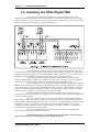
1
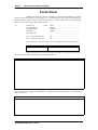
HY02 DIGITAL AUTOMATIC TELEPHONE BALANCE UNIT USER HANDBOOK DHY 02S DHY 02T DHY 02SR DHY 02TR Single automatic TBU, rack mounted with PSU. Twin automatic TBU, rack mounted with PSU. Single automatic TBU, with ringing detector. Twin automatic TBU, with ringing detector. SONIFEX LTD, 1995. All Rights Reserved Revision V1.00c, June 1995 61, Station Road, Irthlingborough, Northants., NN9 5QE, England. Tel : +44 (0)1933 650 700 Fax : +44 (0)1933 650 726 Information in this document is subject to change without notice and does not represent a commitment on the part of Sonifex Ltd. No part of this manual and/or databases may be reproduced or transmitted in any form or by any means, electronic or mechanical, including photocopying, recording, or information storage and retrieval systems, for any purpose other than the purchaser’s personal use, without the express written permission of Sonifex Ltd. Unless otherwise noted, all names of companies, products and persons contained herein are part of a completely fictitious adaptation and are designed solely to document the use of Sonifex products. Warranty and Safety Information Page i Warranty And Safety Information Warranty Registration HY02 Digital TBU Warranty Details The HY02 Digital audio product is guaranteed for 12 months from the date of purchase. The components and materials used are guaranteed against defects and faulty workmanship. Sonifex undertake to replace or repair faulty items at its discretion, within the warranty period, on a return to factory basis. In addition, the HY02 Digital product is a complex microprocessor controlled machine. In order to register the date of purchase it is important to complete the WARRANTY REGISTRATION DOCUMENT and return it to :Sonifex Ltd, 61, Station Road, Irthlingborough, Northants., NN9 5QE ENGLAND The registration document carries the following information for servicing :SERIAL NUMBER COUNTRY CODE DHY______ E A U O Safety Of Mains Operated Equipment HY02 Digital TBU Preparing the Machine for Use Each HY02 Digital TBU is shipped in protective packaging and should be inspected for damage before use. Where an item is found to have transit damage, notify the carrier immediately with all the relevant details of the shipment. Packing materials should be kept for inspection. Connect the equipment in accordance with the connection details and before applying power to the unit, check that the machine has the correct operating voltage for your mains power supply. HY02 Digital TBU User's Guide Page ii Warranty and Safety Information Equipment Safety This equipment has been designed to meet the safety regulations currently advised in the country of purchase. It is important to connect the mains supply in accordance with the information given. SEE BELOW. Ensure that the rear panel mains voltage statement indicates that your equipment is suitable for your mains supply voltage and that the mains supply fuse is correctly rated. The fuse as supplied is correct for the voltage setting. WARNING: This apparatus is intended for use when powered by the HY02-B power supply unit. Other usage will invalidate any approval given to this apparatus if, as a result, it ceases to comply with the edition of BS6301 to which it was approved. WARNING: The equipment B.T. plug should only be connected with apparatus complying with BS6301 and the connection to the network must not be hard wired. Interconnection directly or indirectly with equipment ports marked in accordance with BS6301 to unmarked ports may produce hazardous conditions on the network and advice should be obtained from a competent engineer before such a connection is made. WARNING: This apparatus must be earthed by means of the earth connector on the rear panel, and the B.T. plug should be disconnected from the telecommunications network before disconnecting the earth. Disconnection of this earth connection may render the equipment unsafe, with a consequential possible electrical shock hazard from exposed metallic parts. WARNING: The barriered ports ‘NTTP’ and ‘Handset’ must not be connected directly or indirectly to the unbarriered ports, ‘Line Input’, ‘Line Output’, or ‘Remotes’. This equipment conforms to the safety regulations specified by use of the CE Mark. Voltage Setting Checks The rear panel of the equipment carries the Serial Number of the machine. The operating voltage of the HY02 Digital is selectable by a switch on the power inlet port. Ensure that the machine operating voltage is correct for your mains power supply. The safety specification of your HY02 Digital complies with local requirements and must be earthed through the mains connector. The available voltage settings are : 110V 230V Code A Code E Power Cable and Connection For Class 1 apparatus, the IEC power connector or power lead provided must be connected as follows. The mains lead wires supplied with the equipment are coloured in accordance with the following code : Green Blue Brown - Earth Neutral Live As the colours of the wires in the mains lead may not correspond with the coloured markings identifying the terminals of your plug, proceed as follows :Green and Yellow wire green- - must be connected to the terminal marked with E the colour green or yellow. HY02 Digital TBU User's Guide Warranty and Safety Information Blue wire Brown wire Page iii - must be connected to the terminal marked N or coloured black. - must be connected to the terminal marked L or coloured red. Important Note : The terminal marked on the rear panel must be earthed. Fuse Rating The HY02 Digital is supplied with a single fuse in the live conducting path of the power infeed at the power supply. For reasons of safety it is important that the correct rating and type of fuse is used. Incorrectly rated fuses could present a possible fire hazard, under equipment fault conditions. The fuse ratings for HY02 Digital are :Country code A 110 V operation Country code E 230 V operation - 200mA - 100mA 5 x 20mm SB. 5 x 20mm SB. The active fuse is fitted at the power supply on the outside of the unit. Removing the Covers WARNING : The power must be switched off at the supply or the power lead must be disconnected before attempting to remove the panels or cover. Removal of the panels and cover can expose dangerous voltages. WARNING : The B.T. plug should be disconnected from the telecommunications network exchange line before removing the equipment covers. Limitation of Liability Limited Warranty - Sonifex warrants that (a) the HY02 Digital SOFTWARE will perform substantially in accordance with the accompanying Product Manual(s) for a period of 90 days from the date of receipt; and (b) any Sonifex supplied hardware accompanying the SOFTWARE will be free from defects in materials and workmanship under normal use and service for a period of one year from the date of receipt. Any implied warranties on the SOFTWARE and hardware are limited to 90 days and one (1) year, respectively, or the shortest period permitted by applicable law, whichever is greater. Customer Remedies - Sonifex's entire liability and your exclusive remedy shall be, at Sonifex's option, either (a) return of the price paid or (b) repair or replacement of the SOFTWARE or hardware that does not meet Sonifex's Limited Warranty and which is returned to Sonifex with a copy of your receipt or invoice. This Limited Warranty is void if failure of the SOFTWARE or hardware has resulted from accident, abuse, or misapplication. Any replacement SOFTWARE will be warranted for the remainder of the original warranty period or 30 days, whichever is longer. No other warranties - To the maximum extent permitted by applicable law, Sonifex disclaims all other warranties, either express or implied, including but not limited to implied warranties or merchantability and fitness for a particular purpose, with respect to the SOFTWARE, the accompanying product manual(s) and written materials, and any accompanying hardware. The Limited Warranty contained herein gives you specific legal rights. No Liability for Consequential Damages - To the maximum extent permitted by applicable law, Sonifex and its suppliers shall not be liable for any other damages whatsoever (including, without limitation, damages for loss of business profits, business interruption, loss of business information, or other pecuniary loss) arising out of the use of or inability to use this Sonifex product, even if Sonifex has been advised of the possibility of such damages. In any case, Sonifex's entire liability under any provision of this agreement shall be limited to the amount actually paid by you for the SOFTWARE. This Agreement is governed by the laws of England. Sonifex Ltd can not be held liable for any loss of audio data due to equipment failure. HY02 Digital TBU User's Guide Page iv Warranty and Safety Information Faults Sheet Although this Sonifex product is manufacture to the highest standards, it is possible that minor faults may appear in the equipment over its normal lifetime. If you find any problems with the HY02 Digital, please contact your Sonifex distributor, or contact Sonifex directly at the following address, or fax with a copy of this completed sheet : To : Sonifex Ltd, 61, Station Road, Irthlingborough, Northants. NN9 5QE, UK From: Tel : +44 (0)1933 650 700 Fax : +44 (0)1933 650 726 Name Position Company Address Tel Fax ....................................................... ....................................................... ....................................................... ....................................................... ....................................................... ....................................................... ....................................................... ....................................................... For the Serial No. of your machine, see the back panel of the HY02 Digital unit. HY02 Digital Serial No. HY02 Digital Power Supply Serial No. Please describe the error in as much detail as possible ( for example what you were doing when the problem occurred, what actually happened, etc). Description of HY02 Digital Error Also, if you have any suggestions for additions or upgrades to the HY02 Digital unit , we would like to hear what they are : Additions that I Would Like to See HY02 Digital TBU User's Guide Connection of Apparatus to BT Lines Equipment Type : Sonifex HY02 Digital Telephone Balance Unit BABT Approval Number : NS/3619/123/L/601748 This apparatus is suitable for connection directly to the network by means of the cable mounted plug provided. If you require an appropriate BT socket, or sockets, installed in order to use this equipment then this form should be sent to your local telephone area office. Name Company Address ......................................................................................................... ......................................................................................................... ......................................................................................................... ......................................................................................................... ......................................................................................................... ......................................................................................................... Equipment Type : Sonifex HY02 Digital Telephone Balance Unit BABT Approval Number : NS/3619/123/L/601748 To British Telecom Area Office : Please supply a BT line socket for connection of the above apparatus to : A new line An existing line at the above address. The appropriate equipment details are as above. Signed ..................................... Date .............................. Introduction & Installation Page 1-1 1. Introduction & Installation 1.1. Introduction The HY02 Digital telephone hybrid is a series of equipment presented as either a single channel unit or a twin channel unit mounted within a 1U high 19” rack frame. DHY 02S DHY 02SR Single automatic TBU, rack mounted with PSU. Single automatic TBU, with ringing detector, rack mounted with PSU. DHY 02T DHY 02TR Twin automatic TBU, rack mounted with PSU. Twin automatic TBU, with ringing detector, rack mounted with PSU. DHY 02EC Eurocard version, without ringing detector. This handbook covers the first four pieces of equipment in the above list. In each case the power supply is separately encased within the rack and is connected to the telephone hybrid processor by means of short link cables. The twin channel unit incorporates two separate power supplies within the same enclosed chassis. For the DHY 02S and DHY 02T units, please ignore the section of this handbook which deals with ringing detector, which is not installed in these units. To find out if you have the ringing detector version of the equipment, please check the Serial Number on the rear panel. If the Serial No. is of the format DHYR#### ( instead of DHY#### ), then the unit is installed with the ringing detector. 1.2. Description The telephone hybrid is a two wire to four wire converter which provides the interface between a caller on the telephone line and the input to the mixing desk. Built to a very high specification, it is simple to install and automatically adapts to line conditions and programme content. Analogue signal limiting, controlled from the DSP, is used in the send and receive paths to ensure that signal break-up and severe overload problems do not occur. The unit has independent LED bar graph metering of send and receive levels with input and output gain controls provided at the front panel. Both the input and the output are transformer balanced providing complete isolation. The illuminating line connect control has a remote facility and the equipment is fitted with K-break and dial tone disconnect as standard. Audio connectors are the standard XLR-3 type. By using a high power DSP and a high quality 16 bit dual codec, the HY02 Digital gives some of the best audio figures available - it provides full adaptive echo cancellation to 28msec and gives unwanted sideband rejection figures of 69dBu on tone, reference peak output of +8dB. The HY02 Digital has been designed to achieve the best possible audio performance from a telephone line. The unit ensures that the dynamic range is as large and the distortion and noise are as small as possible. The following product description is necessary for BABT approval and provides information on the connection and operating conditions of the units. HY02 Digital TBU User's Guide Page 1-2 Introduction & Installation 1.2.1. Manufacturer Sonifex Limited, 61 Station Road, Irthlingborough, Northants, NN9 5QE United Kingdom 1.2.2. Equipment Type HY02 Digital telephone balance unit. 1.2.3. BABT Approval Number Apparatus power supply : NS/3619/123/L/601748 1.2.4. Functions The HY02 Digital Telephone Balance Unit is suitable for use with the HY02 power supply for connection to B.T. exchange lines with a series connected telephone at the ‘Handset’ port. The hybrid unit is used as a four wire to two wire converter. Incoming calls received at the handset may be diverted to the hybrid unit and produce a ‘telephone’ signal at the output of the unit. 0dB signals presented at the line input are transmitted to the telephone line only. The HY02 Digital automatically balances the telephone line. 1.2.5. Specified Systems The HY02 Digital is suitable for connection to any exchange line forming part of a Public Switched Telephone Network, PSTN, or a Relevant Branch system for PSTN lines or any extension. This equipment is not suitable as an extension to a payphone. A definition of a Relevant Branch System for PSTN is given in BS6789 : Section 6.1: 1986 clause 2.4 including the NOTE to that clause. 1.2.6. Ringer Equivalence Number The REN=1 marking on the rear of this equipment relates to the performance of the apparatus when used in combination with other items of apparatus. The REN indicates the maximum number of items that should be connected simultaneously to the line. This equipment may be connected with series apparatus up to REN = 4 maximum. 1.2.7. Accessory Ports 1.2.7.1 Barriered Ports The Handset series connection complies with BS6301. 1.2.7.2 Accessory Ports a) Line Input b) Line Output This equipment is provided with a line cord and BT plug to BS6312 and is internally wired as specified in BS6305 1982. HY02 Digital TBU User's Guide Introduction & Installation Page 1-3 1.2.8. Conditions This apparatus is not designed for use under controlled conditions of temperature and relative humidity. 1.2.9. Series Connection This apparatus when connected into the loop connection between the main apparatus and the PSTN introduces a voltage drop at a current of 40mA of 0.300V. The apparatus should not be used in conjunction with other series connected apparatus such that the aggregate declared voltage drops together with that of any relevant wiring at 40mA, exceeds 2.0 volts. 1.2.10.Facilities This apparatus has been approved for use as a telephone hybrid unit (four wire to two wire converter) and for use with a series connected simple telephone. Any other usage will invalidate the approval of the apparatus if as a result it then ceases to comply with the standards against which approval was gained. 1.2.11.Statutory Mark Approved for connection to telecommunications systems specified in the instructions for use subject to the conditions set out in them. 1.3. Specification Feature Clean feed input line Clean feed limiting input Bandwidth to Telephone line Telephone line impedance Telephone line impedance range Output Rejection Ratio Echo Cancellation Power Connections : Input line Output line Telephone line Telephone instrument Remotes Power Earth Bond Screw Value 10kΩ balanced 0dB +6dBu 250Hz - 3500Hz, -3dB ref 1kHz Nominally 600ohm, reactive 300Ω to 1500Ω Balanced floating 0dBu 50Ω Typically 69dB reference peak level of +8dB Network cancellation to 28msec 230V 50Hz XLR 3 pin female ( XLR-3-31 10K ohm balanced floating ) XLR 3 pin male ( XLR-3-32 50 ohm balanced floating ) NTTP BT6/502 cord plug ( plugs into standard line jack socket ) BT605A socket ( accepts standard telephone plug ) 5 way IP40 IEC mains ( CEE22 ) 230V 50Hz Screen terminal bond to earth HY02 Digital TBU User's Guide Page 1-4 Introduction & Installation 1.4. Installing the HY02 Digital TBU Connect the power and earth connections as per the information given in the Warranty and Safety Information section of the handbook. The hybrid unit should be connected with reference to Figure 1-1 below which shows the connections for a twin hybrid. If you are using a single hybrid, please ignore the connections to DHY02 Hybrid Unit 2. The telephone line NTTP port may be directly connected using the BT 6/502 cable mounted connector into a suitable BT wall jack socket. A simple telephone handset can be used to take and make calls when plugged into the equipment handset connector BT 605A. Some versions of this equipment will be supplied with variations of the telephone line or handset connectors. The connector labelled Line Input is balanced bridging and will accept normal signals at 0dBu peaking to +8dBu from a sound mixer ‘clean feed’. The input circuitry to the HY02 Digital has a very effective limiter which will prevent high level overloading problems. The Line Output connection will deliver a balanced/floating low impedance signal of 0dBm from the telephone line. The output of the digital hybrid unit is normally 0dBu from a balanced source of 50 ohms or less across the useful bandwidth of the equipment. The bandwidth is restricted by the line conditions between 250 Hz and 3.5 kHz. The output stage is capable of driving into 600 ohm loads at up to +8dBu. It is not necessary to terminate this output. Isolation of better than 69dB is created between the input and output connectors when the hybrid unit is functioning on an exchange line. The equipment may require some adjustment to work with PBX systems. The power supply creates ± 15V dc to power the electronic hybrid processor from a 230V, 50Hz ac supply. The power unit has an overvoltage protected output and is fully isolated and totally enclosed. Earth bonding from the IEC power connector is carried through the connection cable and multiway socket to the electronic hybrid processor unit. The earth terminal at the rear of the equipment provides protection for the user against dangerous line fault conditions. A remote divert switch may be connected at the Remotes socket. There are external preset gain controls available to the user for setting both the Receive and Transmit levels through the equipment. The earth bond at the screw terminal must be connected to a technical earth to ensure the safe operation of the equipment under all line conditions. HY02 Digital TBU User's Guide Introduction & Installation Page 1-5 1.5. Using the HY02 Digital 1.5.1. Receiving a Call With the equipment connected as in Figure 1-1, calls may be received and detected by the ringer in the telephone handset. To receive the call, lift the handset and establish contact with the caller. The call may be diverted to the telephone hybrid by pressing either the local Line Connect switch at the front panel or by means of the Remote Divert switch. The hybrid unit will now act as a 4 wire to 2 wire converter with a signal input at the Line Input and telephone signal output at the Line Output. When the equipment is on, the On LED indicator will be illuminated and when an incoming call is seized the Hold indicator will be illuminated. The call may be cleared by re-pressing the Line Connect switch ( which can be remoted ), or by means of the K-break provided in the equipment. Automatic line clearance is provided when the caller hangs up, if jumper JP2 is set ( default condition ). If the DHY 02TR or DHY 02SR have been purchased, which contain the integrated ringing detector, the call will be picked up automatically and passed to the telephone hybrid ( This will happen if jumper JP3 has been set , which is the default configuration ). The ring number on which the detector will pick the call up can be adjusted from 1 to 5 by altering RV3 ( Default value is 2 rings ). With both auto-answer and auto-clearance in use, call handling can be completely automatic in operation. 1.5.2. Making a Call To initiate a call, lift the Handset and dial the required telephone number. When the call has been established, press the Line Connect switch and the call will be handed over to the telephone hybrid unit. To clear the line at the end of the call, press the Line Connect switch. The Line Connect switch lamp is off in the non-connected mode and on in the connected mode. Please note that any adjustments and settings should be carried out by competent engineering personnel. 1.6. Front Panel Controls and Displays 1.6.1. LED Indicators There are two LED indicators providing general information about the equipment : A status LED, marked “On”, shows that the equipment is powered and operational. A line hold LED indicates when the telephone line is seized and connected. 1.6.2. Bar Graph LED’s Additionally there are independent LED bar graph displays of 10 elements each showing the relative levels of both the received and transmitted signals. The presence of signals within the normal zone up to the maximum level , before limiting takes place, is an indication of normal operation. The 0dB level mark indicates the safe level for signal operation. The three red LED indicators above this mark indicate headroom of +6dB above the 0dB level. Signals sent to the line can be monitored at the Tx level bar graph and any adjustments in level can be set by the Tx gain control preset. Signals received from the telephone line can be monitored at the Rx level bargraph and the signal levels set by the Rx gain control preset. The Tx and Rx levels must not exceed the maximum bar graph display, to prevent distortion and breakup. The Rx and Tx bar graphs can be used to set the Rx and Tx gains using test tones and a small flat-blade screw-driver. HY02 Digital TBU User's Guide Page 1-6 Introduction & Installation 1.6.3. Line Connect Switch This is the front panel button used to connect calls to and disconnect calls from the telephone line. It can be remoted by using the Remote Divert switch and the connection signal can be made permanent or momentary by adjusting jumper setting JP1. 1.6.4. Transmit and Receive Level Adjustment To the left of the LED bar graph meters are two holes which can be used to adjust the level of the transmitted and received signals. Inside the holes are a three way switch which can be adjusted by use of a small flat-blade screw-driver : 1.6.4.1 Receive Level The level of the input received by the unit depends on which of the three settings is selected. With the switch set to low, a -12dB signal received is output at 0dB. Selecting the Medium or High settings add +6dB and +12dB to the level respectively. Set the level so that the meter readings peak at the 0dB scale mark. The receive switch is set to Low by default. 1.6.4.2 Transmit Level The level of the output sent by the unit depends on which of the three settings is selected. With the switch set to low, -12dB is sent to the line for a reference 0dB input signal. For the Medium and High settings, -6dB and 0db respectively are sent to the line ( i.e. +6dB increase in level each time ). Use the Low setting for high level input ( where the LED bar graph is always going to the end of the meter ). Use the High setting for low level input ( where the bar graph meter never reaches the 0dB point ). The transmit switch is set to Medium by default. Setting High Medium Low HY02 Digital TBU User's Guide Receive Level ( ref 0dB output ) +12dB +6dB 0dB Transmit Level ( ref 0db input ) 0dB -6dB -12dB Introduction & Installation Page 1-7 This section of the handbook answers some of the popular questions asked about the HY02 Digital unit and the way that it operates. If you have any questions regarding the operation of the HY02 Digital, please contact your nearest distributor, or Sonifex directly. Q : Why do I need a telephone balance unit ? A : To convert a two wire telephone pair ( duplex ) to a four wire ( 2 simplex ) one input pair and one output pair. Q : What is a mix-minus signal and why do I need one ? A : A mix-minus signal ( also called a clean-feed ) is an output from the mixing console which includes signals from all of the audio channels except the channel that is allocated to the telephone line. It is the signal that is used in the TBU send input, which is sent to the caller on the telephone line. There are two reasons why the clean-feed signal is needed : Firstly, the TBU is designed to separate the caller audio from the desk output audio, with an output consisting mostly of the caller audio. If the caller audio is sent to the TBU send input, a feedback loop is created ( causing howling on the line ) and the hybrid can not separate the two signals. Secondly, the caller should hear what the other listeners are hearing and not hear themselves. Q : What are the main advantages between a conventional analogue hybrid and the HY02 Digital ? A : There are two : The main advantage is that the HY02 Digital rejects signals equally across its frequency band which results in a much better total rejection ratio. The second advantage is that the HY02 Digital can handle line echo and reflections of up to 28msec. This provides dramatic improvements on rejection ratios over satellite links. Q : Can I use open speakers with the HY02 Digital ? A : Yes. Due to the echo cancellation, the HY02 Digital can cope with a high level of acoustic feedback without it becoming unstable. HY02 Digital TBU User's Guide Page 1-8 Introduction & Installation This page deliberately blank HY02 Digital TBU User's Guide Circuit Description & Controls Page 2-1 2. Circuit Description & Controls The HY02 Digital Telephone Hybrid consists of two parts separately enclosed for safety within a 19” rack frame housing. The two parts are connected by linking cables at the rear of rack frame. Isolation is achieved by means of the barriers created at the power supply and the hybrid electronics. 2.1. Mains Power Unit Circuit Description The mains power is available in either single or double configuration for use with either one or two electronic hybrid units, within one rack frame assembly. The 230V 50Hz mains connection is via an IEC fused connector type CEE22. The 230V supply generates low voltage a.c. through an isolation transformer(s) TR1 (TR2) the outputs of which are smoothed and regulated to ±15 d.c. by means of the electronic regulators Q1 and Q2 (Q3, Q4) ± 15V connected to the electronic hybrid together with an earth bond and remote connections through the power cable at the rear of the power supply. The ± 15V d.c. output of the power is protected against high voltage breakdown by d.c. fuses F1, F2 (F3, F4) and the voltage sensitive zener diodes D1, D2 and (D7, D8) in the twin configuration. A single overvoltage fault will cause overvoltage current to flow in D1 and D2 (D7, D8) rupturing fuses F1, F2 (F3, F4) removing the overvoltage condition. 2.2. Electronic Digital Hybrid Unit Circuit Description The electronic digital hybrid unit comprises the following sections (see block diagram, Figure 2-1 ). 2.2.1 Input circuits and limiter. 2.2.2 Telephone line barrier and transformer. 2.2.3 Output circuits. 2.2.4 Divert switch logic. 2.2.5 Line balancing electronics. 2.2.6 Ring detect circuits. 2.2.7 Dial tone detect circuits. 2.2.8 Displays 2.2.1. Input Circuits and Limiter The line input connection at the XLR-3-31 is coupled directly to the line bridging input transformer TR2. The input impedance is greater than 10K ohms balanced floating with a high common mode rejection ratio. The input transformer is coupled to the limiter transistors Q24 and Q25 and amplifier Q3b via R50, C26, C27 and R52. The limiter output delivers full bandwidth signals which drives the digital processor. Analogue signal limiting controlled from the DSP is used in the send and receive paths to ensure that signal break-up and severe overload problems do not occur. The telephone send circuit drives the line via a transformer/capacitor/divert relay combination. The receive circuit uses an independent transformer coupled bridging circuit. This is connected to the send circuit in two wire mode and to a separate input for four wire operation. An analogue sidetone cancellation network is switched in if the board is ‘on-line’ and in two wire mode. HY02 Digital TBU User's Guide Page 2-2 Circuit Description & Controls HY02 Digital TBU User's Guide Circuit Description & Controls Page 2-3 2.2.2. Telephone Line, Barrier and Transformer The telephone line port is a two wire connection into the apparatus through a line cord and jack BT 6/502, with a surge arrestor BT 14A from the A and B wires to earth. The line connection is switched by a divert switch and relay between the hybrid unit and the handset connected through a BT 605A connector. The line is held, on the equipment side, by an electronic line holding circuit Q29, Q28 and Q27, the A leg fed through a 2.2 uF 250V d.c. blocking capacitor to the line transformer TR1 (ETAL P1200). A pair of zener diodes arranged in a back to back configuration across the primary of the line transformer, are arranged to act as overvoltage protection. The line transformer is designed to meet BS 6305. Figure 2-2 shows a schematic diagram of this part of the ciruitry. 2.2.3. Output Circuits The output from the codec Q36 is presented at balanced line level via a servo balanced output stage. Amplifier Q2d and transistors Q31 and Q32 form a low impedance push-pull amplifier driving the output balancing transformer TR3. The diodes D21 and D22, R72 and R71 form a bias chain for the drive transistors. The input at Q2d is filtered by R79 and C43 a simple low pass filter. The balanced output at TR3 is less than 50 ohms at the frequencies used and has a high common mode rejection. The output signal at TR1 consists of the telephone line signal only, with the local clean feed content nulled out to better than -69dB ref +8dB peak output. 2.2.4. Divert Switch Logic With the system unenergised the logic connects the telephone line to the handset through relay RL1 relaxed contacts. The logic circuits Q1a and Q1b change the state of the relay contacts via Q17, Q36, Q1f and Q5, diverting the telephone line to the equipment, when the divert switch is activated. The logic is edge triggered and will accept remote commands. This logic also drives the indicator lamp at the switch and remote lamp contacts. The logic holds the relay in the divert condition until either power is removed or the switch is operated again. K break and dial hang up tone will also untrigger the latch when required to do so. A signal from the logic operates input muting when the handset is in use preventing spurious output signals at the equipment. HY02 Digital TBU User's Guide Page 2-4 Circuit Description & Controls 2.2.5. Line Balancing Electronics The DHY 02 is designed to achieve the best possible audio performance available from a telephone line. To this end, a high quality 16 bit dual codec is used. The equipment ensures that the dynamic range is as large, and the distortion and noise are as small as possible. The send audio signal from the codec is processed via the DSP before being sent to the telephone line. The send signal is checked for excess level and the input analogue signal is limited as above if the signal is found to be overloading. The signal is then high-pass filtered, and, if enabled, acoustic cancellation is implemented. 2.2.5.1 Duplex Control Transmit/receive path level locking : Off position : Low position : High position : No processing. +12dB dynamic levelling. +24dB dynamic levelling. Attack and release time 1dB per 5msec. Hysteresis 8dB for no processing. 2.2.5.2 Adaption System Network cancellation of 28ms. Double-talk detection and normalised adaptive FIR system used with pink noise cancellation 2.2.5.3 Send Circuit Transmit set to low : Maximum output (soft limited) Sensitivity for max output : Maximum input level : Distortion at -1dBM to line : Output noise to line : 0dBM +6dB +20dB 0.1% -71dB Tx LED sensitivity : Frequency response : -14dB on, -17dB off -3dB at 250Hz, flat until 3.5kHz Dynamic control profile as below : Input Output +20dB +10dB 0dB -10dB -20dB 30dB 40dB 50dB 0dB 0dB 0dB -10dB -22dB -41dB -57dB -66dB Attack: 125mS, decay, 1dB per 5mS Transmit set to medium : As above, but input 0dB for 0dBM to line. Transmit set to high : HY02 Digital TBU User's Guide Circuit Description & Controls Page 2-5 Maximum output level to line (soft limited) : +6dBM Tx LED sensitivity : -7dB on, -10dB off Output noise to line : -66dB 2.2.5.4 Receive Circuit Receive set to low: Gain : Maximum output : Distortion : Maximum input level : Noise : Rx LED sensitivity : Frequency response : +9dB +8dB (soft limited) 0.1% before limiting 20dBm -66dB (-77dB off line) -14dB on, -17dB off at output -3dB 250HZ, flat to 3.5 kHz. The cancellation uses FIR filters with a normalised signal dependent adaption algorithm. The adaption is disabled during double-talk and when the signals are too low in level. The adaption coefficients are held digitally and are not subject to drift when no signals are present. Typically 40dB of rejection is achieved with real signals although 60dB rejection can be measured using test signals into dummy lines. Send and receive levels are set up by on-board links. Although the board works in full duplex mode, links can program signal dependent half duplex operation; this enhances the overall sidetone rejection/stability with little degradation to the apparent full duplex operation. 2.2.5.5 Hardware Control The DSP is used to control all facets of the operation of the board. On power up, the digital devices are checked for correct operation and a status led flashes if errors are found. The DSP reads the onboard links and sets the operational mode signal levels accordingly. The DSP also controls the divert status of the board via the codec auxiliary data I/O channel. The signals are software ‘debounced’ for stable operation. The send and receive LEDS are processed via the DSP. These have hysterisis built in to minimise ‘chattering’. The divert relay and two/four wire mode control is driven via the DSP. The signal is checked for overload, and digitally limited if needed. The ‘Tx LED’ is turned on if the outgoing signal is above -14dB and the Tx signal is gain reduced if found to be below 24dB. The Tx level is adjusted before being sent to the codec send port. The signal is processed in 16/32 bits throughout, to maintain good audio performance. The receive signal from the codec is processed via the DSP before being presented to the output. The receive signal is checked for excess level and the input analogue signal is limited if the signal is overloading. The signal is then high-pass filtered and, if enabled, network cancellation is implemented. The signal is checked for overload and digitally limited if needed and the receive is disabled if the board is ‘off line’. The ‘Rx LED’ is turned on if the signal is above -14dB and signal is gain reduced ( i.e. noise reduction is introduced ) if it is below -24dB. The signal is also gain reduced if levelling is desired, and the send signal is dominant. Receive level is adjustable from 9 to 21dB. 2.2.5.6 Digital Cancellation Control Fixed sidetone cancellation occurs in two wire mode prior to DSP processing. Full adaptive network cancellation is achieved by DSP means. Echo cancellation is 28ms. 2.2.6. Ring Detect Circuits The ring detector circuit is optional. It is permanently coupled to the telephone line at the handset relay contacts and is isolated from the line by the optocoupler Q13. Ringing tones are detected by the circuitry formed by Q12, Q11, Q10 and Q9. Ring sensitivity is adjusted by RV3. The output of the ring detector is coupled to the divert switch latch by Q7 and the jumper connection JP3. HY02 Digital TBU User's Guide Page 2-6 Circuit Description & Controls The ringing detector can be set to auto answer after 1 to 5 ring tone bursts by means of RV3. 2.2.7. Dial Tone Detectors Dial tones presented to the equipment at the termination of a call, ( hang up tone ) can be detected by the equipment and can be used to disconnect the HY02 Digital from the telephone line as an automatic process. Since there are several hang-up tones in use worldwide, there are jumper settings at JP8, JP9 and JP10 to select the various possibilities : a) Single or dual tones b) Pulsed or continuous tones c) Long or short cadences. The tone frequencies are detected by two independent tone decoders Q33 and Q34 each with centre frequency setting presets RV2 at 350 Hz and RV1 at 440 Hz. Detected signals are processed by the logic at Q35 and present an unlatching signal to the disconnect circuitry at Q22. Alternatively when the caller hangs up the line voltage increases. This is detected by Q27 and coupled by opto-isolator Q21 which creates a disconnect signal at Q22. This disconnection is the K break. 2.2.8. Displays There are two LED indicators on the front panel which provide general information about the equipment : A status LED shows that the equipment is on. A line hold LED indicates that a telephone line is seized and connected. Additionally there are independent LED bar graph displays of 10 elements each showing the relative levels of both the received and transmitted signals. The presence of signals within the normal zone up to the maximum level before limiting takes place is an indication of normal operation. The Rx and Tx bar graphs can be used to set the Rx and Tx gains using test tones. The LED displays are driven by Q15 and Q16 controlled from the DSP Q20 data bus outputs and have law shaping elements controlled within the DSP software. There are also three LEDs mounted directly on the circuit board which provide information about the transmit and receive signals and status information : The LD1 Status LED indicates any error conditions at switch on by means of a flash code : Number of Flashes 3 4 5 6 Error Q18 error. Q19 Test 1 error. Q19 Test 2 error. Q36 Codec IRQ error. The flashing stops after approximately one minute and then begins a high speed read/write of the device in question. If any of these errors should occur, please contact your nearest Sonifex distributor. LD2, the transmit LED, and LD3, the receive LED, are on whenever transmitting and receiving respectively. HY02 Digital TBU User's Guide Circuit Description & Controls Page 2-7 2.3. Alignment Controls The following alignment controls and jumpers are provided within the equipment for setting the general operating parameters. For the position and layout of the preset alignment controls, see Figure 2-3, overleaf. For normal operation of the equipment, these controls will not need to be altered.“Set” or “Enabled” implies that the jumper is on. Do not adjust these settings without consulting a technical information file. 2.3.1. Jumpers JP1 JP2 JP3 JP4 JP5 JP6 JP7 JP8 Controls whether the Remotes connections are actuated by momentary or permanent contacts. Set over 1 & 2 for momentary. Set over 2 & 3 for permanent. Set for line disconnect ( default ). If the caller hangs-up, this will drop the line off using K-break. Set for auto answer. The ringing detector circuitry must be fitted. Factory set on pins 2 & 3 - do not adjust. Factory unset - do not adjust. Factory set on pins 1 & 2 - do not adjust. Link for instant reset. Controls disconnect tones : Set for single tone, unset for dual tone (UK). JP9 JP10 JP11 JP12 JP13 Controls disconnect tones : Set for pulse tone ( Belgium, France ), unset for continuous disconnect ( UK ). Controls disconnect tone burst : Set for long burst ( 4 secs ), unset for short ( 2 secs ) disconnect tone burst ( UK ). It is the length of time that the line tone has to be present before the automatic disconnect operates. Set for dial tone detect ( hang up tone ). If JP2 is connected and the Kbreak has failed, this will automatically hang the line up. Line connect enable. This is factory set and should not be adjusted. Not used 2.3.2. Preset Potentiometers RV1 is RV2 RV3 This sets the frequency of the primary 440 Hz disconnect tone. Range 250 - 550 Hz. This sets the frequency of the secondary 350 Hz disconnect tone. Range is 250 - 550 Hz. This sets the number of rings before operation of the ringing detector between 1 and 5 rings. 2.3.3. LEDs LD1 LD2 LD3 Status LED provides error message information ( See Section 2.2.8 ). Transmit LED is on whenever transmitting. Receive LED is on whenever receiving. HY02 Digital TBU User's Guide Page 2-8 Circuit Description & Controls HY02 Digital TBU User's Guide Connection Details Page 3-1 3. Connection Details All of the connections are located on the rear of the HY02 Digital : The connections are as follows:- 3.1.1. Mains Power IEC Connector ( CEE22, 230V, 50Hz ) 3.1.2. Line Input The line input is an XLR 3 pin female connector ( XLR-3-31, 10k ohm balanced floating ). Pin 1 : Pin 2 : Pin 3 : Screen Phase Non-phase 3.1.3. Line Output The line output is an XLR 3 pin male connector ( XLR-3-32, 10k ohm balanced floating ). Pin 1 : Pin 2 : Pin 3 : Screen Phase Non-phase 3.1.4. Remotes The HY02 Digital is equipped with a 5 way IP40 connector which is assigned as follows : Pin 1 Pin 2 Pin 3 Pin 4 Pin 5 : : : : : Lamp Hybrid Unit 1 Divert Switch ( Line Connect ), Hybrid Unit 1 Common Lamp Hybrid Unit 2 Divert Switch ( Line Connect ), Hybrid Unit 2 HY02 Digital User's Guide Page 3-2 Connection Details 3.1.5. Power The Hybrid units are connected to the central power supply by a 7 way IP 40 connector with the following assignments : Pin 1 Pin 2 Pin 3 Pin 4 Pin 5 Pin 6 Pin 7 : : : : : : : +15V -15V Common Earth Earth Remote line connect switch Remote line connect lamp 3.1.6. Protective Earth Terminal This terminal must be connected. HY02 Digital User's Guide Page 0 Index HY02 Digital TBU User's Guide Contents Warranty And Safety Information .................................................................. i Warranty Registration....................................................................................................i HY02 Digital TBU ............................................................................................................i Warranty Details ............................................................................................................. i Safety Of Mains Operated Equipment ..........................................................................i HY02 Digital TBU ............................................................................................................i Preparing the Machine for Use ....................................................................................... i Equipment Safety ........................................................................................................... ii Voltage Setting Checks .................................................................................................. ii Power Cable and Connection ......................................................................................... ii Fuse Rating .................................................................................................................... iii Removing the Covers ..................................................................................................... iii Limitation of Liability ....................................................................................................... iii Faults Sheet ....................................................................................................................iv 1. Introduction & Installation.......................................................................... 1-1 1.1. Introduction .............................................................................................................1-1 1.2. Description...............................................................................................................1-1 1.2.1. Manufacturer......................................................................................................... 1-2 1.2.2. Equipment Type.................................................................................................... 1-2 1.2.3. BABT Approval Number........................................................................................ 1-2 1.2.4. Functions .............................................................................................................. 1-2 1.2.5. Specified Systems ................................................................................................ 1-2 1.2.6. Ringer Equivalence Number ................................................................................. 1-2 1.2.7. Accessory Ports.................................................................................................... 1-2 1.2.7.1 Barriered Ports.......................................................................................................1-2 1.2.7.2 Accessory Ports .....................................................................................................1-2 1.2.8. Conditions............................................................................................................. 1-3 1.2.9. Series Connection ................................................................................................ 1-3 1.2.10. Facilities.............................................................................................................. 1-3 1.2.11. Statutory Mark .................................................................................................... 1-3 1.3. Specification ............................................................................................................1-3 1.4. Installing the HY02 Digital TBU..............................................................................1-4 1.5. Using the HY02 Digital ............................................................................................1-5 1.5.1. Receiving a Call.................................................................................................... 1-5 1.5.2. Making a Call ........................................................................................................ 1-5 1.6. Front Panel Controls and Displays........................................................................1-5 1.6.1. LED Indicators ...................................................................................................... 1-5 1.6.2. Bar Graph LED’s................................................................................................... 1-5 1.6.3. Line Connect Switch ............................................................................................. 1-6 1.6.4. Transmit and Receive Level Adjustment............................................................... 1-6 1.6.4.1 Receive Level ........................................................................................................1-6 1.6.4.2 Transmit Level .......................................................................................................1-6 1.7. Questions and Answers .........................................................................................1-7 2. Circuit Description & Controls................................................................... 2-1 2.1. Mains Power Unit Circuit Description ...................................................................2-1 2.2. Electronic Digital Hybrid Unit Circuit Description................................................2-1 2.2.1. Input Circuits and Limiter ...................................................................................... 2-1 2.2.2. Telephone Line, Barrier and Transformer ............................................................. 2-3 2.2.3. Output Circuits ...................................................................................................... 2-3 2.2.4. Divert Switch Logic ............................................................................................... 2-3 2.2.5. Line Balancing Electronics.................................................................................... 2-4 2.2.5.1 Duplex Control .......................................................................................................2-4 2.2.5.2 Adaption System....................................................................................................2-4 2.2.5.3 Send Circuit ...........................................................................................................2-4 2.2.5.4 Receive Circuit.......................................................................................................2-5 2.2.5.5 Hardware Control...................................................................................................2-5 2.2.5.6 Digital Cancellation Control....................................................................................2-5 2.2.6. Ring Detect Circuits .............................................................................................. 2-5 2.2.7. Dial Tone Detectors .............................................................................................. 2-6 2.2.8. Displays ................................................................................................................ 2-6 2.3. Alignment Controls .................................................................................................2-7 2.3.1. Jumpers................................................................................................................ 2-7 2.3.2. Preset Potentiometers .......................................................................................... 2-7 2.3.3. LEDs..................................................................................................................... 2-7 3. Connection Details ...................................................................................... 3-1 3.1.1. Mains Power ......................................................................................................... 3-1 3.1.2. Line Input.............................................................................................................. 3-1 3.1.3. Line Output ........................................................................................................... 3-1 3.1.4. Remotes ............................................................................................................... 3-1 3.1.5. Power ................................................................................................................... 3-2 3.1.6. Protective Earth Terminal ..................................................................................... 3-2 Index ................................................................................................................. I-1 HY02 Digital TBU User's Guide HY02 Digital TBU User's Guide Index Power Supply Circuit Description, 2-1 Connections, 1-1 Power Supply Connection, 1-4 PSTN Suitability, 1-2 A Adjustments, 2-7 Alignment of Equipment, 2-7 B BABT Approval Number, 1-2 Barrier Circuitry, 2-3 BS6301 Connector, ii Q Questions and Answers, 1-6 R Rear Panel Drawing, 3-1 Receive Level, 1-5 Receive Level Adjustment, 1-4 Remote Connections, 3-1 Remote Divert, 1-5 REN Value, 1-2 Reporting Faults, iv Ringing Detector Circuitry, 2-5 Use, 1-5 C Call Making, 1-5 Receiving, 1-5 CE Mark, ii Circuit Description, 2-1 TBU, 2-1 Connection Details, 3-1 Connections, 3-1 D Dial Tone Detection Circuitry, 2-6 Divert Switch Circuitry, 2-3 S Safety of Equipment, i, ii Serial Number, 1-1 Specification, 1-3 Summary of Functions, 1-1 E Earth Warning, ii Earth Connection, 1-4, 3-2 Equipment Function, 1-1 Equipment Safety, ii T Telephone Line Circuitry, 2-3 Transformer Circuitry, 2-3 Transmit Level, 1-5 Transmit Level Adjustment, 1-4 Type of Equipment, 1-1 F Faults Sheet, iv Front Panel Drawing, 1-1 Fuse Rating, iii G Guarantee, i H Handset Use, 1-5 I Input Circuits, 2-1 Installing, 1-4 J Jumper Settings, 2-7 K K-Break, 1-5 L LED Bar Graph Level Indicators, 1-5 Front Panel Displays, 2-6 Front Panel Indicators, 1-5 Information, 2-7 PCB LED Displays, 2-6 Limitation of Liability, iii Limiter, 2-1 Line Balancing Circuitry, 2-4 Line Connect Switch, 1-5 Line Input Connections, 1-4, 3-1 Line Output Connections, 1-4, 3-1 M Mains Lead Connection, ii Model Types, 1-1 N NTTP Port connection, 1-4 O Options, 2-7 Output Circuitry, 2-3 P Potentiometer Settings, 2-7 Power Connections Between Power Supply & TBU, 3-2 Power Connector, 3-1 HY02 Digital TBU User's Guide V Voltage Settings, ii W Warranty, i