1
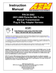
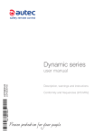
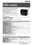
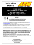
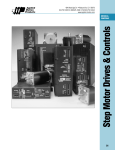
LIUAIR1AU0-02 - A0LIBR00D0131
AIR series
manuale per l’operatore
user manual
23
INDEX
1 Description of the AIR series' radio remote controls ..............................................................
1.1 How the radio remote control works .....................................................................................
1.2 Applications ...........................................................................................................................
1.3 Technical Data ......................................................................................................................
1.4 Safety Functions ...................................................................................................................
1.5 Identifying the radio remote control .......................................................................................
24
24
24
24
25
26
2 Conformity and frequencies ...................................................................................................... 26
2.1 Frequency band 433.040-434.790 MHz ............................................................................... 26
2.2 Frequency band 915-928 MHz ............................................................................................. 27
3 Risk assessment ........................................................................................................................
3.1 Risk assessment for radio remote controlled machines .......................................................
3.2 Staff training ..........................................................................................................................
3.3 Working conditions ................................................................................................................
27
28
28
29
4 A8 transmitting unit ....................................................................................................................
4.1 Description of the A8 unit ......................................................................................................
4.2 Operation ..............................................................................................................................
4.3 Warnings for use ...................................................................................................................
4.4 Battery AIRBM3V7L ..............................................................................................................
4.5 Docking station AIRDOCK01 ................................................................................................
30
30
30
32
34
34
5 Receiving unit .............................................................................................................................
5.1 Description of G type receiving unit ......................................................................................
5.2 Description of type L receiving unit .......................................................................................
5.3 Operation ..............................................................................................................................
5.4 Warnings for installation ........................................................................................................
35
35
36
36
37
6 Radio remote control maintenance ..........................................................................................
6.1 Routine maintenance ............................................................................................................
6.2 Special maintenance .............................................................................................................
6.3 Malfunctions ..........................................................................................................................
39
39
41
41
7 Machine maintenance ................................................................................................................ 43
8 Disposal ....................................................................................................................................... 43
CAPTION
This symbol indicates an important warning that, if disregarded, leads
to a hazardous situation for people and property.
@
This symbol indicates a document that can be found in the specific section
on Autec's website.
The documentation must be kept for the whole life of the radio remote control: after
reading it, keep it on hand for future reference.
Contact Autec if any of the instructions and/or warnings provided in this document
are not clear. No part of this document may be reproduced, in any form or by any
means, without written permission of Autec (including recording and photocopying).
LIUAIR1AE0-02.fm
AUTEC - AIR series
24
Description of the AIR series' radio remote controls
How the radio remote control works
1 Description of the AIR series' radio remote controls
1.1
How the radio remote control works
Industrial radio remote controls are used to control machines from a distance, without physical connection between the user and the machine (i.e. wires or connecting cables). They
consist of a portable transmitting unit, from which the user remotely controls the machine,
and a receiving unit installed on board the machine itself.
The two units constantly communicate with one another through a radio link. They automatically search for a free working frequency.
The two units use messages coded through an address that is unique (produced by Autec
only once) and univocal (specific for each radio remote control).
1.2
Applications
AIR series' radio remote controls can be installed on hoisting and material handling machines
(i.e. overhead cranes).
As required by standards ISO 12100 and ISO 14212, risk assessment must be carried out
for each machine (see chapter 3). The radio remote control can only be used if this assessment gives positive results. However, this radio remote control cannot be installed:
- on machines installed in places where equipment with explosion-proof characteristics is required
- on machines for moving, raising and transporting people.
- on machines that may generate dangerous situations if they stop due to the loss of radio
link
1.3
Technical Data
Command response time (typical).............................................................................. 100 ms
Working range (typical) ..................................................................................................50 m
Stop time (typical)...................................................................................................... 100 ms
Max. stop response time ............................................................................................... 0.5 s
Performance Level of safety functions according to EN ISO 13849-1:
Stop protection .............................................................................................................. PL d
Protection against unintended movements from the standstill position (UMFS) .......... PL c
AUTEC - AIR series
Description of the AIR series' radio remote controls
25
Safety Functions
Temperature
Relative
Humidity
Air Pressure
Transportation
Radio
remote control
Class 2K4
-40°C to +70°C
(-40°F to +158°F)
Class 2K4
95%
Class 2K4
70 kPa to 106 kPa
Storage
Radio
remote control
Class 1K5
-40°C to +70°C
(-40°F to +158°F)
Class 1K3
5% to 95%
Class 1K5
70 kPa to 106 kPa
Transmitting unit
Class 4K4H
-20°C to +55°C
(-4°F to +130°F)
Class 4K4H
4% to 100%
Class 4K4H
70 kPa to 106 kPa
Receiving unit
Class 4K4H
-20°C to +70°C
(-4°F to +158°F)
Class 4K4H
4% to 100%
Class 4K4H
70 kPa to 106 kPa
Use
A8 transmitting unit
Power supply (battery AIRBM3V7L) ................................................................ Li-ion 3.7 V
Antenna..................................................................................................................... internal
Housing material ............................................................................................ PA 6 (20% fg)
Protection degree............................................................................................................IP65
Dimensions ...................................................... 64.5 x 179 x 37.5 mm (25.5 x 70.5 x 15 In)
Weight .......................................................................................................... 250 g (0.55 Lb)
Run time (at 20°C / 68°F) .............................................................................................. 40 h
Receiving unit
Power supply .............................................................. 45 - 240 V~ (max 40 - 264 V~ 0.4 A)
optional for type G receiving unit ............................... 12 - 24 V (max 9 - 30 V 1 A)
Antenna..................................................................................................................... internal
STOP contact rated current ...............................................................................4 A (250 V~)
SAFETY contact rated current ...........................................................................4 A (250 V~)
Command contact rated current.........................................................................6 A (250 V~)
Housing material ............................................................................................ PA 6 (20% fg)
Protection degree............................................................................................................IP65
Dimensions .......................................................... 123 x 202 x 83 mm (48.5 x 79.5 x 33 In)
Weight ........................................................................................................... 1.2 kg (2.7 Lb)
1.4
Safety Functions
Autec radio remote controls are equipped with some functions that provide high safety levels,
in order to safeguard the safety of people and property.
1.4.1 Stop
The stop function brings the machine to a safe state every time it is necessary to stop it due
to a potentially hazardous situation. Depending on the situation, this function can either be
deliberately activated by the operator through the STOP pushbutton, or it is automatically ac-
LIUAIR1AE0-02.fm
AUTEC - AIR series
26
Conformity and frequencies
Identifying the radio remote control
tivated when the radio link is incorrect or interrupted (the receiving unit autonomously stops
the radio remote control).
1.4.2 Protection against unintended movements from the standstill position (UMFS)
This safety function protects the system “machine+radio remote control” from unintended
movements, namely machine movements not activated intentionally by the user, but resulting from possible electrical and mechanical failure of the radio remote control.
Such safety function checks the neutral (rest) position of pushbuttons controlling the machine's movements. Each time one of those pushbuttons is operated, the transmitting unit
sends both the movement command and the SAFETY command.
1.5
Identifying the radio remote control
As required by standard IEC 60204-32 , each radio remote control is uniquely identified
through a serial number (S/N).
The S/N is provided in the identification plate in the two units.
2 Conformity and frequencies
2.1
Frequency band 433.040-434.790 MHz
2.1.1 Conformity
Each AIR series' radio remote control working in the frequency band 433.040-434.790 MHz
complies with the (R&TTE) Directive 1999/5/EC and its essential requirements.
Each radio remote control is also in conformity with the harmonised standards provided in
the EC Declaration of Conformity.
@
You can find the EC Declaration of Conformity in the specific section of Autec website,
under “After Sales Service”.
2.1.2 Frequencies
The radio link between the units of Autec AIR series radio remote controls is built at one of
the frequencies permitted by the European standards in force when the system is put on the
market.
Frequencies used in the frequency band 433.040-434.790 MHz...................................... 64
RF power................................................................................................................... <1 mW
Channel spacing........................................................................................................ 25 kHz
2.1.3 Market
Air series' radio remote controls working in the frequency band 433.040-434.790 MHz can
be used within the EU (European Union) and the EFTA (European Free Trade Association).
AUTEC - AIR series
Risk assessment
27
Frequency band 915-928 MHz
2.2
Frequency band 915-928 MHz
2.2.1 Conformity
Each AIR series' radio remote control working in the frequency band 915-928 MHz complies
with the essential requirements of the following regulations:
- FCC (Federal Communication Commission) Part 15
- IC (Industry Canada) RSS-102
Unit
FCC ID
IC number
A8
OQA-A08LA0AM
9061A-A08LA0AM
Receiving unit G
OQA-RGAAA00M
9061A-RGAAA00M
Operation is subject to the following two conditions:
(1) this device may not cause harmful interference, and
(2) this device must accept any interference received, including interference that may cause
undesired operation.
Changes or modifications not expressly approved by the party responsible for compliance
could void the user’s authority to operate the equipment.
2.2.2 Frequencies
The radio link between the units of Autec AIR series radio remote controls is built at one of
the frequencies permitted by the US and Canadian standards in force when the system is put
on the market.
Frequencies used in the frequency band 915-928 MHz ................................................. 256
RF power............................................................... complies with FCC and IC requirements
Channel spacing ........................................................................................................ 50 kHz
2.2.3 Market
Air series' radio remote controls working in the frequency band 915-928 MHz can be used in
the US and Canadian markets.
3 Risk assessment
Always evaluate whether the machine can be radio remote controlled. In fact, as required by
technical standards specific to the market where the system “machine+radio remote control”
is used, each machine must undergo risk assessment and risk analysis.
The radio remote control can only be installed if this assessment gives positive results.
The machine manufacturer and/or the person who decides upon radio remote
control installation and use is responsible for this risk assessment.
Autec cannot be held responsible if this assessment has not been carried out correctly or is incomplete.
LIUAIR1AE0-02.fm
AUTEC - AIR series
28
Risk assessment
Risk assessment for radio remote controlled machines
If required by the risk assessment, draw up protection measures to prevent, reduce and report potential hazard situations.
3.1
Risk assessment for radio remote controlled machines
When carrying out risk assessment for the machine or for the system where the radio remote
control is installed, the following must be considered:
- some machines cannot be radio remote controlled: check for forbidden applications (see
paragraph 1.2)
- the radio link between the two units may be interrupted due to persistent disturbance or
interference.
- all warnings related to installation, use and maintenance provided by Autec must be taken
into account
3.1.1 Aspects related to radio link
Whenever the radio link is interrupted (i.e. stop, low battery, automatic switch off, receiving
unit not powered):
- all outputs in the receiving unit are disabled: if this generates a hazardous situation, the
corresponding commands on the machine must be kept active
- it is not possible to enable or disable the machine commands until the radio remote control
is started up again.
3.1.2 Delay in command response time
Due to the characteristics of radio propagation (i.e.: EM interference, out-of-working-range
condition), a delay up to the "Maximum stop time" may occasionally occur from the moment
a command in the transmitting unit is released to the moment its corresponding output in the
receiving unit is deactivated.
Those who decide upon the installation of the radio remote control must make sure that this
delay never leads to a dangerous situation in the specific uses.
3.1.3 Protection from unintended activation
The transmitting unit housing is manufactured so that it protects the actuators from unintentional activation, while meeting at the same time the operating needs, the comfort requirements and law limits.
Assessment shall be made to establish possible additional protection measures for the actuators (i.e. commands requiring two-hand operation, “dead-man” function) if particular environments, equipment and working modes could cause accidental bumps to the actuators.
3.2
Staff training
All installation, usage and maintenance operations must be carried out by qualified technicians who are suitably trained with respect to:
- warnings resulting from risk assessment
- regulations and reference laws
- instructions and warnings provided in the documents related to the industrial radio remote
control and to the radio remote controlled machine
AUTEC - AIR series
Risk assessment
29
Working conditions
- instructions provided by those who install the radio remote control on the machine and by
the person in charge for workplace safety where the system machine+radio remote control
is used
3.3
Working conditions
To guarantee correct radio remote control operation, all current regulations regarding safety
at work and accident prevention should be respected. All applicable standards and regulations valid in the user country regarding the use of both the machine and the radio remote
control must always be respected.
Autec cannot be held responsible if the radio remote control is used in unlawful working conditions.
LIUAIR1AE0-02.fm
AUTEC - AIR series
30
A8 transmitting unit
Description of the A8 unit
4 A8 transmitting unit
4.1
Description of the A8 unit
LEDs
Screw and battery cover
STOP pushbutton
Command pushbuttons
Technical data plate
FUNCTION pushbutton
Identification plate
Contacts for recharge
START pushbutton
4.2
Operation
4.2.1 Start up with PIN code
As required by standard IEC 60204-32, the radio remote control start up is protected by a PIN code, in order to prevent non authorised use of the machine.
During the start up phase, press each pushbutton within 3 seconds from the release of the
previous pushbutton, or the transmitting unit will switch off.
Start up through factory-set PIN
When the receiving unit is powered on, perform the following procedure:
1) press the START pushbutton until the green LED illuminates
2) press the FUNCTION pushbutton
3) press the START pushbutton until the green LED blinks slowly.
STOP
STOP
1
2
3
R
G
4
R
G
4
1
2
3
R
G
4
S1
S2
S1
S2
S1
S2
FUNCT.
START
FUNCT.
START
FUNCT.
START
1) START
AUTEC - AIR series
STOP
1
2
3
2) FUNCTION
3) START
A8 transmitting unit
31
Operation
Start up through customised PIN
If the risk analysis requires this, the PIN code may be modified to prevent unauthorised use.
The procedure to set a customised PIN is provided in the document “Menu of Transmitting Unit (MTU)”; you can find this document in the dedicated section on Autec's
website.
@
When the receiving unit is powered on, perform the following procedure:
1) press the START pushbutton until the green LED illuminates
2) press the pushbutton sequence PIN 1, PIN 2 and PIN 3 related to the PIN code provided
in the technical data sheet (if PIN 1 and/or PIN 3 is the START pushbutton, it is not to be
considered as part of the code sequence)
3) press the START pushbutton until the green LED blinks slowly.
STOP
STOP
1
2
3
R
G
4
STOP
1
2
3
R
G
4
STOP
1
2
3
R
G
4
STOP
1
2
3
1
2
3
R
G
4
R
G
4
S1
S2
S1
S2
S1
S2
S1
S2
S1
S2
FUNCT.
START
FUNCT.
START
FUNCT.
START
FUNCT.
START
FUNCT.
START
PIN 1
1) START
PIN 2
2) PIN
PIN 3
3) START
4.2.2 Command activation
Press pushbuttons related to the commands you want to carry out.
4.2.3 Light signals during operations
Green LED
- steady on: transmitting and receiving unit do not comRed LED
municate with each other
Green LED
- blinks fast: the radio remote control starts when the
STOP
START pushbutton is pressed
- blinks slowly (one blink per second): it is possible to
send commands
Red LED
- steady on at power on: the STOP pushbutton is activated or damaged
- blinks twice at power on: at least one of the commands is activated or damaged
- blinks 3 times at power on: the unit is discharged
- on for 2 s: the unit does not work correctly
- blinks slowly: approx. 4 h run time left
- blinks fast: 10 min run time left
PD5580-00
Signals from the other four LEDs depend on the function matching the FUNCTION pushbutton (or on digital inputs, if wired on the G receiving unit).
LIUAIR1AE0-02.fm
AUTEC - AIR series
32
A8 transmitting unit
Warnings for use
4.2.4 FUNCTION pushbutton
The FUNCTION pushbutton can be matched with different relay functions on the receiver's
side (see technical data sheet).
4.2.5 STOP
The STOP pushbutton should be pressed when it is necessary to stop the machine immediately when a dangerous condition should occur.
When the STOP pushbutton is pressed, the machine stops and the transmitting unit switches
off.
To start working again after the STOP pushbutton has been pressed, do the following:
- make sure that the working and usage conditions are safe
- pull or turn the STOP pushbutton in the arrow direction to unlock it
- start up the radio remote control.
4.2.6 Switching off
The A8 unit automatically switches off in the following cases:
- voluntary switch off when the START pushbutton and immediately afterward the FUNCTION pushbutton are deeply pressed for 3 seconds
- as a response when the STOP pushbutton is pressed
- automatic switch off when there are no enabled commands for a predetermined timeframe.
This timeframe is provided tin the technical data sheet (SWITCH-OFF).
Before the A8 unit switches off automatically, the green and red LEDs blink alternating for
30 seconds.
4.3
Warnings for use
In addition to all instructions provided by the machine manufacturer, by the installer of the
radio remote control and by the person responsible for the safety of the work area, users shall
always respect the following warnings.
Before starting to work, the user shall do the following:
- stand in a position that allows the direct supervision of the remote controlled
machine and its load, and stay in a place ensuring safety conditions in respect of other operations and/or activities and/or processes that are carried
out in the working environment;
- never start up or use the transmitting unit if the working conditions present
the risk of losing balance or tripping;
- always check that the mechanical operation of the STOP pushbutton is correct. If it is impossible or difficult to press this pushbutton, do not use the radio remote control;
- only start up the transmitting unit when starting work: improper use may
cause hazardous situations;
- never start up or use the transmitting unit in closed spaces, with the machine
not in sight, or outside the radio remote control working range: in such cases
it is in fact still possible to build a radio link, thus causing the risk that unwanted commands be carried out by the machine;
AUTEC - AIR series
A8 transmitting unit
33
Warnings for use
- get familiar with the correspondence between the pushbuttons and the machine's movements (this is indicated in the attached technical data sheet) and
learn symbols on the panel of the A8 unit (symbols used are defined by the
machine manufacturer and/or installer depending on the machine's operation
and functions).
During normal operation, the user shall do the following:
- visually and directly follow all movements of the machine and its load and remain inside the radio remote control working range;
- use the transmitting unit in a simple and comfortable way, avoiding accidental falls; the hand strap (wrist band) provided with the radio remote control is
used for that purpose;
- pay particular attention to warnings and visual/acoustic signals, and take all
measurements and steps to avoid that movements of the remote controlled
machine leads to hazardous situations for people and/or property;
- pay attention to the entire work area. Immediately press the STOP pushbutton
when a hazardous situation occurs;
- pay attention to the low battery signals. The A8 unit cannot be used during
the charging process; all dangerous operations (i.e. hanging load) must
therefore be brought to an end before the battery is completely flat;
- in case of malfunction, disable the system “machine+radio remote control”
until the problem has been completely solved.
After using the radio remote control, the user shall do the following:
- switch off the transmitting unit when work is stopped or temporarily interrupted. Do not leave the load hanging (even while recharging the unit);
- never leave the transmitting unit unattended if it is on.
LIUAIR1AE0-02.fm
AUTEC - AIR series
34
A8 transmitting unit
Battery AIRBM3V7L
4.4
Battery AIRBM3V7L
The A8 unit contains a rechargeable battery; the provided battery is partially charged.
The document “Battery AIRBM3V7L” shall be understood and kept into account to
correctly use the A8 unit and its battery; you can find this document in the dedicated
section on Autec website.
Do not throw the batteries away with domestic trash. Apply local rules when
disposing of them: different collection and recycling schemes for batteries in
compliance with are the 2006/66/EC Directive and amendments.
@
4.4.1 Recharging the A8 unit
First power on the docking station with its power supply unit and then:
1) insert the A8 unit into the docking station: a steady on red
1b
LED indicates that charging has started (max. 4 h)
2) remove the A8 unit from the docking station when necessary
Note: when the green LED switches on, the A8 unit is completely charged.
Charge the unit at a temperature between 5°C and 45°C.
2b
1a
4.4.2 Indication of A8 unit run time
Perform the following procedure to check the transmitting unit's run time:
1) switch off the transmitting unit and unlock the STOP pushbutton
2) keep pushbuttons S1 and START pressed until the 3 left LEDs illuminate
showing the unit's run time (3 illuminated LEDs correspond to the highest
run time).
Run time indication disappears after some seconds.
1
2
3
R
G
4
1
2
3
R
G
4
MAX.
4.5
1
2
3
R
G
4
MIN.
Docking station AIRDOCK01
The docking station AIRDOCK01 is used to recharge the A8 unit.
Plug in the adapter in the socket on the back of the docking station.
The adapter works with 100 - 240 V~ (optional 10 - 30 V ).
@
Respect instructions provided in the document “Docking station AIRDOCK01” to correctly use the docking station itself;
you find this document in the dedicated section on Autec website.
AUTEC - AIR series
2a
STOP
S1
1
2
3
S1
R
G
4
S2
FUNCT. START
START
Receiving unit
35
Description of G type receiving unit
5 Receiving unit
Technical data plate
Identification plate
ENABLE LED
POWER LED
5.1
Cable gland
Description of G type receiving unit
Command outputs
F1: power supply fuse
Connector for power supply
Digital inputs
Fuses of SAFETY circuit
Electronic module
Fuses of STOP circuit
SAFETY outputs
STOP outputs
DIP switches
Internal light signals
Fuse F1 ......................................................................................... 1.6 A F 250 V (5x20 mm)
Fuses F2 and F3 ............................................................................. 4 A T 250 V (5x20 mm)
Fuses F4 and F5 ............................................................................. 4 A T 250 V (5x20 mm)
LIUAIR1AE0-02.fm
AUTEC - AIR series
36
Receiving unit
Description of type L receiving unit
5.2
Description of type L receiving unit
Internal light signals
Power supply fuse
Connector for power supply
Fuses of SAFETY circuit
Electronic module
Fuses of STOP circuit
SAFETY outputs
STOP outputs
DIP switches
Command outputs
Fuse F1 ......................................................................................... 1.6 A F 250 V (5x20 mm)
Fuses F2 and F3 ............................................................................. 4 A T 250 V (5x20 mm)
Fuses F4 and F5 ............................................................................. 4 A T 250 V (5x20 mm)
5.3
Operation
5.3.1 Electronic module
The electronic module contains the address key, where the radio remote control configuration data are also stored. The receiving unit cannot work without this address key.
5.3.2 DIP switches
These two DIP SWITCHes shall always be set at OFF: do not modify this setting.
5.3.3 External signal lights
The ENABLE LED is off: the receiving and transmitting units are not communicating.
The ENABLE LED blinks: receiving unit G is ready to receive commands sent by the transmitting unit
The POWER LED is on: the receiving unit is powered on.
AUTEC - AIR series
Receiving unit
37
Warnings for installation
5.3.4 Internal light signals
The activation of each relay on the mother board is signalled by an LED near the relay.
5.3.5 Command outputs
The data sheet contains information regarding the correspondence between the commands
sent by the transmitting unit and the related output enabled in the receiving unit.
5.4
Warnings for installation
The radio remote control can only be installed and tested by competent staff that masters the
technical knowledge required to carry out such procedure and is qualified according to the
regulation of the country where the radio remote control is installed. Only if the radio remote
control is installed correctly can it be used safely.
Besides instructions established by the machine's manufacturers, installers must always observe the following warnings.
5.4.1 General
Respect and enforce the provisions of all reference standards relevant in the
concerned application field (i.e. EN IEC 60204-32 for hoisting machines).
Always follow the instructions provided in the technical data sheet to carry out
correct installation.
5.4.2 Mounting and fastening the unit in the best position
The receiving unit shall be positioned as follows:
- in a place that can be easily reached in case of need
- vertical, with the cable gland or the plug facing down, and possibly facing the
work area
- at least 50 cm far from metal objects in its surroundings and never inside
closed metal containers.
If this warning is disregarded, the radio remote control working range may be reduced.
Fix the receiving unit in four points, using the specific holes in the housing.
When installing on machines that vibrate, it is recommended to fix the receiving
unit to the machine with the appropriate vibration dampers.
Do not perforate the receiving unit in any case.
LIUAIR1AE0-02.fm
AUTEC - AIR series
38
Receiving unit
Warnings for installation
5.4.3 Positioning the antenna
The antenna is inside the receiving unit. Hence, install the receiving units so
that shields, structures or materials do not obstruct the radio link; in particular:
- the receiving unit shall not be placed inside closed metal containers
- the receiving unit must be placed at least 50 cm far from metal objects in its
surroundings.
If this warning is disregarded, the radio remote control working range may be reduced.
5.4.4 Wiring
The receiving unit's AC power supply must be as follows:
- be protected against short circuit
- have a switch that allows power supply disconnection during installation,
wiring and/or maintenance operations.
Pay special attention to the currents flowing in the SAFETY and STOP outputs:
they shall not exceed the maximum permitted values.
To obtain the UMFS protection, connect the contact of the SAFETY relay in series with the movement commands.
fuse
common wire input
movement commands common wire
selection commands common wire
Group the wiring away from the electronic module, in order to avoid interferences and hazards related to electrical safety.
The STOP circuit in the receiving unit has two contacts connected in series
through the bridge between terminal 34 and 35 (producer standard wiring). If
the machine needs a STOP circuit with two separate contacts (four wires), this
bridge can be removed. In this case, the installer is responsible for wiring in a
way that assures the required safety level.
5.4.5 At end of installation
Make sure that during installation the safety mechanisms on the radio remote
control and/or in the machine have not been made ineffective by possible procedures carried out.
Correctly close the receiving unit so that the protection degree from dust and
water is not jeopardised: check that the gasket is intact, correctly put the housing parts one over the other so that they overlap, and screw in the screws.
AUTEC - AIR series
Radio remote control maintenance
39
Routine maintenance
5.4.6 Testing
After installing and wiring the receiving unit, test the system “machine+radio
remote control”, and check that the operations carried out correspond exactly
to the commands sent (in particular check the STOP command).
The installer must check and complete the "Technical Data Sheet" in all its
parts, adding the date the system has been put into service, his stamp and signature.
In case of malfunction, disable the system “machine+radio remote control” until the problem has been completely solved.
6 Radio remote control maintenance
The following instructions provide information to safely carry out routine and special maintenance operations for the radio remote control.
They shall be completed by:
- instructions provided by the machine manufacturer
- directions provided by the installer of the radio remote control on the machine
- regulations regarding safety at work and accident prevention in force in the country where
the radio remote control is used.
All fine-tuning, checking and maintenance actions carried out on the radio remote control
shall be verified and recorded by the person in charge of carrying out maintenance on the
machine.
In case of malfunction or damaged parts, disable the system “machine+radio
remote control” until the problem has been completely solved.
Before any maintenance operation, disconnect power supply from the receiving unit.
After any maintenance operation:
- always make sure that commands sent by the transmitting unit only activate
the corresponding expected operations
- if the transmitting unit has been opened, close it correctly, in order not to endanger its protection degree from dust and water: check that the gasket is intact, correctly overlay the two parts of the housing and tighten the screws.
6.1
Routine maintenance
Routine maintenance consists of operations needed to preserve the radio remote control normal usage conditions, thus implementing fine-tuning, checks, planned replacement actions
that necessarily arise from the normal use of the product.
All given instructions must be followed correctly at each commissioning, that is:
- whenever the radio remote control and/or the machine is installed or assembled
- whenever the machine location/position changes
- after special maintenance.
LIUAIR1AE0-02.fm
AUTEC - AIR series
40
Radio remote control maintenance
Routine maintenance
Routine maintenance carried out as described in this manual is fundamental for using the radio remote control safely.
Special applications may need more specific routine maintenance actions to be carried out
at different periods (i.e. if the working environment is particularly dirt, in case of heavy applications or if the system is used very frequently, some maintenance actions may be required
more frequently, depending on the decision of the person in charge for safety in the worksite).
6.1.1 Daily routine maintenance
Before starting to work:
- make sure that the recharging contacts are always clean
- make sure that the pushbuttons' gaskets are intact, soft and elastic
- make sure that the transmitting unit panel symbols can be easily recognised and replace
the panel if necessary
- check that the three plates on the transmitting unit are readable and intact
- make sure that the mechanical operation of the STOP pushbutton is correct.
During normal operation:
- check structural integrity of the transmitting unit
- make sure that materials that could endanger the transmitting unit usage and safety (such
as concrete, sand, lime, dust) do not deposit on it.
After using the radio remote control:
- clean the transmitting unit: never use solvents or flammable/corrosive materials and do not
use high-pressure water cleaners or steam cleaners
- store the transmitting unit in clean and dry areas.
6.1.2 Three-month routine maintenance
Every three months:
- remove dust or deposit of material from the receiving unit: never use solvents or flammable/corrosive materials to clean it, and do not use high-pressure water cleaners or steam
cleaners
- check structural integrity of the receiving unit
- make sure that the wiring of the receiving unit is intact and connected
- make sure that the receiving unit panel symbols can be easily recognised and replace the
panel if necessary
- check that the plates on the receiving unit are readable and intact.
6.1.3 Six-month routine maintenance
Every six months:
- make sure that all the relay contacts of the receiving unit operate correctly, and check that
the contact closes when the corresponding manoeuvre is enabled and opens when the
manoeuvre is disabled
- check the correct correspondence between the commands that are sent and the manoeuvres that are carried out by the machine
AUTEC - AIR series
Radio remote control maintenance
41
Special maintenance
- check that the contact of the SAFETY relay is open when no movement command has
been sent. This is safety critical maintenance: it is necessary to keep a record (date, signature, comments) showing that this check has been regularly carried out. Keep the record
together with other installation documents.
6.2
Special maintenance
Special maintenance consists of repairs needed due to radio remote control failure, damage
or malfunction, carried out with the aim of restoring the original usage and working conditions.
Prior to contacting the support service technicians:
- read and understand all documents related to the radio remote control, and make sure that
all the instructions they contain have been accomplished correctly
- follow the instructions to detect possible malfunctions and their origins.
Any fault should be repaired by authorised personnel only (contact the support service of the machine's manufacturer), using original Autec spare parts only.
The following radio remote control data must be reported in order to make interventions faster and more reliable:
- radio remote control serial number (S/N)
- purchase date (given on the certificate of guarantee)
- description of the problem found
- address and telephone number of the place where the device is being used (with the name
of the person to contact)
- local supplier.
6.3
Malfunctions
When the radio remote control does not work:
- bring the transmitting unit close to the receiving unit to avoid radio interference and disturbances
- establish whether the problem lies with the radio remote control or with the machine.
Therefore, before any inspection, try to control the machine from a control unit different from
the radio remote control, if present.
If the problem persists, it lies with the machine.
Look for radio remote control malfunctions as follows.
LIUAIR1AE0-02.fm
AUTEC - AIR series
42
Radio remote control maintenance
Malfunctions
6.3.1 Signals on the transmitting unit
If the problem persists after the suggested solution has been carried out, contact the support
service.
Green
LED
Signals
Possible reason
Solutions
Steady on
Start up the radio remote control.
The transmitting and receiving If the radio remote control does
not start up, check that the reunit do not communicate.
ceiving unit is powered on.
Blinks
fast
The radio remote control is not Press the START pushbutton unstarted up.
til the green LED blinks slowly.
Blinks slowly
The radio remote control is See paragraph “Signals on the
(one blink per second) started up.
receiving unit”.
Steady on at power on
Blinks twice
at power on
Red
Blinks three times
at power on
On for 2 s
Blinks slowly
Green and Red
Blinks
fast
The STOP pushbutton
locked or damaged.
is
Unlock the STOP pushbutton.
At least one of the commands Bring the actuators to the rest pois enabled or damaged.
sition.
The unit is discharged.
Recharge the unit.
The unit does not work corContact the support service.
rectly.
Approx. 4 h run time left
Bring the system “machine+radio
remote control“ to a safe state as
soon as possible and recharge
the unit.
10 min run time left.
Bring the system “machine+radio
remote control“ to a safe state
and recharge the unit.
Blink alternating
30 s left before the unit auto- The auto switch off time is reset
matically switches off.
by pressing any pushbutton.
The green LED blinks
at power on and the
red LED is steady on
Perform the PAIR procedure to
The transmitting unit is not
match the transmitting unit with a
paired with any receiving unit.
receiving unit.
AUTEC - AIR series
Machine maintenance
43
Malfunctions
6.3.2 Signals on the receiving unit
If the problem persists after the suggested solution has been carried out, contact the support
service.
LED
Signals
Possible reason
Solutions
The connecting plug between
the radio remote control and Correctly plug in the connecting
the machine is not connected plug.
correctly.
POWER
Switched off
Illuminated
Fuse F1 is damaged.
Replace the fuse.
Wrong or no power supply.
Make sure that power supply
wires are correctly connected
and that the power supply value
is within the limits specified in the
technical data.
Receiving unit is powered.
Make sure that the outputs are
correctly wired and that the power supply is within the limits provided the technical data.
Start up the radio remote control.
The transmitting and receiving
Start up the radio remote control.
unit do not communicate.
Blinks
Make sure that commands sent
Radio remote control is startenable the corresponding relays
ed up: the unit is ready to reand that the relays go back to the
ceive commands from the
rest position when the command
transmitting unit.
is released.
ENABLE
Switched off
7 Machine maintenance
Follow instructions provided by the machine manufacturer and by the installer of the radio
remote control, in order to carry out machine maintenance.
When carrying out maintenance on the machine, always disconnect power supply from the receiving unit.
Disconnect all receiving unit's electrical connections whenever machine maintenance is carried out (i.e. when soldering).
8 Disposal
When disposing of a radio remote control, give it to the waste separate collecting services in
the user's country.
LIUAIR1AE0-02.fm
AUTEC - AIR series
44