1
Intelligent Inverter
Instruction Manual
Introduction
Introduction
We thank you for purchasing our “TOYO ED Motor System”.
The intelligent inverter “ED64A series” is RoHS complying inverter for Interior permanent
magnet synchronous motor (ED motor) drive.
This instruction manual is designed to explain the correct procedures for installing, wiring and
operating inverter for ED motor drive “ED64A”. Carefully read this instruction manual prior to use.
Also, ED motor system is provided with motor “EDM series” usage direction other than “ED64A”, so
please read together.
“ED64A” Inverter has many characteristic functions in addition to the standard ones. Complied
with many applications, the most suitable system can be structured using many kinds of functions:
“HC (Super-block) function” and “sequence (PLC) function” etc.
In such a case prefer the value written in the relevant instruction manual and test report, to the
values shown separately.
Though “ED64A” series is upper compatible of the function of conventional “ED64A” series
come parts such as 3022 and 3044 outline size are changed. Please be careful when using with
changed to conventional “ED64A”.
2
READ PRIOR TO USE
READ PRIOR TO USE
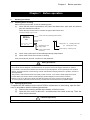
Safety precautions
Before installing, operating, maintaining and inspecting the inverter, carefully read this instruction
manual and all other appendices, and handle it correctly. Before using it, get acquainted with the details
of the devices, safety information and all safety instructions before use.
In this instruction manual, the safety instructions are classified into two ranks, WARNING and
CAUTION.
!
WARNING
!
CAUTION
Indicates a hazardous situation which will result in death or serious injury if the
inverter is handled improperly.
Indicates a hazardous situation which may result in moderate or minor injury or
only in properly damage if the inverter is handled improperly. However, such a
situation may lead to serious accidents depending on circumstances.
These signal words indicate important instructions. Follow the instructions
without fail.
CAUTION (Installation)
!
Install the inverter on a metallic or nonflammable surface.
Otherwise, it may cause a fire.
Do not place flammable materials near the inverter.
Doing so may cause a fire.
Do not carry the inverter by the front cover.
The inverter may drop and cause personal injury.
Install the inverter on a surface that withstands its weight.
Otherwise, it may drop and cause personal injury.
Do not install or operate the inverter if it is damaged or have any of its parts missing.
Operating the inverter in such a state may cause personal injury.
!
WARNING (Wiring)
Before wiring, make sure that the input power is off.
Failure to do so may cause an electric shock or a fire.
Connect the earth wire surely.
Failure to do so may cause an electric shock or a fire.
The inverter shall be wired by electric engineering technicians.
Wiring by unauthorized persons may cause an electric shock or a fire.
Wire the inverter after installing the main body.
Failure to do so may cause an electric shock or a fire.
!
CAUTION (Wiring)
Do not connect AC power to the output terminals (U, V and W). Doing so may cause an injury or a fire.
Check that the rated voltage of the product is identical with the voltage of AC power.
If not, injury or a fire may occur.
Do not connect a resistance directly to the DC terminal 1 or between 2 and or 1 and 2.
Doing so may cause a fire.
3
READ PRIOR TO USE
WARNING (Operation)
!
Turn on the input power after fitting the front cover.
Do not remove the cover while power is on. Doing so may expose you to shock hazard.
Do not operate any switch with wet hands.
Doing so may expose you to shock hazard.
Do not touch the inverter terminal while power is on, even if the inverter is in the stopped state.
Doing so may expose you to shock hazard.
Do not touch the inverter terminal while the ED motor is running.
Doing so may expose you to shock hazard.
The stop button is effective only when the use of its function has been specified.
Separately prepare an emergency stop switch. Failure to do so may cause an injury.
If the alarm is reset with the operation signal kept input, the inverter will suddenly restart.
Reset the alarm after making sure that the operation signal is off. Failure to do so may cause personal injury.
CAUTION (Operation)
!
The radiating fin and the radiating resistance are hot. Do not touch them.
Doing so may cause a burn.
The inverter can be set to operate in a wide range of speed. Operate the inverter after sufficiently checking the
allowable range of the motor and the machine. Failure to do so may cause personal injury.
If a holding brake is necessary, separately prepare it. Failure to do so may cause personal injury.
!
WARNING (Maintenance, inspection and replacement of parts)
Before inspecting the inverter, turn off the input power, and wait for 10 minutes or more to make sure that the
motor is stopped.
Check the DC voltage between 1 and or 2 and to confirm that the voltage is 30 V or less. Failure to
do so may cause an electric shock, personal injury and a fire.
Check that the rated voltage of the product is identical with the voltage of AC power.
If not, personal injury or a fire may occur.
Unauthorized persons shall not maintain or inspect the inverter or replace its parts.
For maintenance and inspection, use insulated tools. If not, may cause an electric shock or personal injury.
!
WARNING (Other)
Never modify the inverter.
Doing so may cause an electric shock or personal injury.
General precautions
Some illustrations given in this instruction show the inverter from which the covers or safety shields have been
removed to illustrate the details. Before operating the inverter, return the covers and shields to their positions as
specified, and operate it in accordance with the manual.
These safety precautions and specifications stated in the manuals are subject to change without notice.
4
Contents
Contents
Introduction...........................................................................................................................................2
READ PRIOR TO USE ..........................................................................................................................3
Safety precautions ........................................................................................................................3
Contents ................................................................................................................................................5
Chapter 1
1.
2.
3.
Before operation ..............................................................................................................7
Handling procedures...........................................................................................................7
Connection ........................................................................................................................11
Terminal block and specifications.....................................................................................12
Chapter 2
1.
2.
3.
4.
5.
6.
7.
Operation of ED64A .......................................................................................................14
Checking before operation ...............................................................................................14
Switches and LEDs on control PCB (VFC2001-Z) ...........................................................16
Functions of console panel (SET64-Z) .............................................................................17
Auto-tuning........................................................................................................................24
Procedures for test running ..............................................................................................31
Changing inverter control mode .......................................................................................33
Operations after replacement of PCB ..............................................................................34
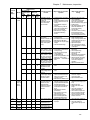
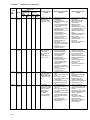
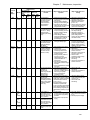
Chapter 3 Explanation of function setting items .........................................................................35
1.
List of ED64A setting items ..............................................................................................36
2.
Explanation of setting items ..............................................................................................47
Chapter 4
1.
2.
3.
4.
5.
6.
7.
8.
Selection and option......................................................................................................86
Selection guide .................................................................................................................86
Input/output device and wiring ..........................................................................................87
AC reactor (option) ...........................................................................................................89
Noise filter .........................................................................................................................90
DC reactor.........................................................................................................................91
VF61R / VF64R sine wave converter ...............................................................................91
Dynamic braking unit (DB unit) .........................................................................................91
Standard corresponding ...................................................................................................92
Chapter 5
1.
2.
3.
4.
Function-up option ........................................................................................................94
Insulation input card : ISO64 ............................................................................................94
Insulation input/output card: IO64-Z .................................................................................94
Motor temperature detection option : T/V61V ..................................................................95
Structuring network ...........................................................................................................96
Chapter 6
1.
2.
3.
4.
5.
System-up option ...........................................................................................................97
HC function .......................................................................................................................97
Sequence (PLC) function .................................................................................................97
Trace back monitor function .............................................................................................97
Trend monitor function ......................................................................................................97
Console data set function .................................................................................................97
Chapter 7 Maintenace, inspection .................................................................................................98
1.
ED64A protection display and trouble shooting ...............................................................98
5
Contents
2.
3.
4.
Chapter 8
1.
2.
3.
4.
Periodic inspection ......................................................................................................... 104
Insulation resistance test ............................................................................................... 105
Disposal ......................................................................................................................... 105
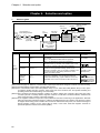
Standard specifications ............................................................................................. 106
Common specifications.................................................................................................. 106
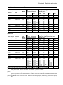
List of models ................................................................................................................. 108
List of capacities ............................................................................................................ 109
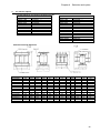
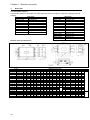
Outline dimension .......................................................................................................... 110
Chapter 9 Cautions when consulting us .................................................................................... 115
6
Chapter 1
Chapter 1
1.
Handling procedures
1-1.
Checking when receiving
Before operation
Before operation
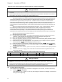
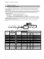
When receiving the product, check the following points.
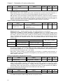
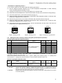
(1)
Check that the product specifications are proper and attachments, spare parts and optional
parts are delivered as ordered.
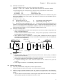
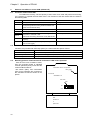
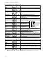
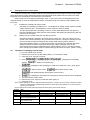
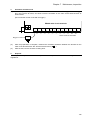
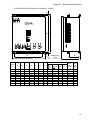
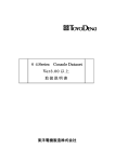
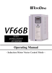
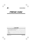
Check the logo on the cover to confirm the type of the inverter unit.
Example of marking of type on cover
Inverter series name (indicating ED64A Series)
ED64A
3722
Input 3 200 to 230 V
Model
37 22
50/60 Hz
OUTPUT 37kW 32.5A
Specification of input
supply voltage
Voltage class 22: Indicating 200V class
(44: Indicating 400V class)
Output capacity Indicating 37 kW
Inverter output capacity
and current
(2)
Check if the product has not been damaged during transportation.
(3)
Check if the screws are not loose or missing.
If any nonconformity is found, contact us or the distributor.
!
Safety precautions
Carefully read the instruction manual prior to use, and use the inverter correctly.
Our inverters are not designed or manufactured for the purpose of use in life-support machines or systems.
If you intend to use the product stated in this document for special purposes, such as passenger cars, medical
devices, aerospace devices, nuclear energy controls and submarine relaying machines or systems, consult our
sales department.
This product is manufactured under strict quality control. However, if it is used in critical equipment in which
inverter failure may result in death or serial damage, provide safeguard to avoid serious accidents.
ED64A is only for our ED motor. Please note that this inverter can not be used to except for ED motor.
To use this product, electrical work is necessary. The electrical work must be done by qualified expert.
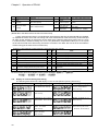
1-2.
Opening the front cover
To operate the DIP switches on the control PCB for maintenance or auto-tuning, open the front
cover in accordance with the following procedures.
(1) Remove the mounting screws at the bottom of the front cover.
(2) Open the front cover to about 45, and disconnect the hooks at the top. Then, the
cover can be removed.
!
CAUTION (Operation)
When opening the cover right after operation, wait until the CHG lamp on the main circuit PCB goes out.
7
Chapter 1
Before operation
WARNING(Cautions when replacing part)
!
Do not disassemble the inverter needlessly.
After disassembling the inverter, check that the units are correctly assembled.
Incorrect assembly may cause a fire.
If the flat cable is not inserted correctly, the control circuit may malfunction. Carefully insert the cable.
Tighten the screws securely.
1-3.
Installation location
The conditions in the installation location affect the life and reliability of the inverter.
using it in the following places. Use it under the conditions specified in the catalog.
(1)
(2)
(3)
(4)
(5)
Avoid
If the inverter is installed in a highly humid or dusty place, or in a place exposed to water or
oil, the circuit insulation will be deteriorated, and the life of the parts will be shortened.
If the working ambient temperature is too high, the life of the capacitor and cooling fan motor
will be shortened.
In a place with corrosive gas, connector contact failure, breaking of electric wires and
damage of parts may be caused.
In a place with heavy vibration, connector contact failure, breaking of electric wires and
damage of parts may be caused.
If the inverter is used at an ambient temperature of 0C or less, use a heater to increase the
temperature to more than 0C at the start of the inverter. After the inverter starts, it generates
heat by itself to more than 0C and will operate normally.
!
CAUTION (Installation)
Install the inverter on a metallic or nonflammable surface. Otherwise, it may cause a fire.
Do not place flammable materials near the inverter. Doing so may cause a fire.
Do not carry the inverter by the front cover. The inverter may drop and cause personal injury.
Install the inverter on a surface that withstands its weight. Otherwise, it may drop and cause personal injury.
Do not install or operate the inverter if it is damaged or any of its parts is missing.
Operating the inverter in such a state may cause personal injury.
1-4.
Installing the unit
To use ED64A inverter installed in a control panel, follow the state below.
!
WARNING(Installation procedure)
Improper installation may cause an electric shock or a fire.
(1)
Installation direction
Install ED64A inverter vertically with the logo “ED64A” up. If installed horizontally, it will not
be ventilated sufficiently and will be overheated. Enough consideration must be given to the
routes of suction and exhaust of air.
The cooling fan in the unit sucks air from the bottom and exhausts air to the top. Keep a
sufficient space above the unit so that ventilation is not prevented by wiring ducts, etc.
(2)
When installing the inverter with the fin out of the rear of the control panel
ED64A-3722, 3744 or less can be installed on a control panel with the cooling fin out from
the rear of the control panel.
ED64A-4522, 4544 or more are also able to be installed on a control panel with the fin out
from the control panel, but it cannot isolate air between the inside and outside of the
panel.
Consult us for the heat release values of parts other than the fin.
8
Chapter 1
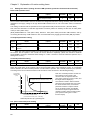
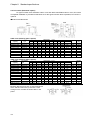
(3)
Before operation
Example of inverter loss
The loss of ED64A inverter is 2.5 to 5% of the motor load capacity.
Example:
37 kW 5% = 1850 W
When the motor load is 37 kW, the loss is 1850 W.
The percentages of loss corresponding to various inverter capacities are shown below.
11 to 37 kW: 5%
45 to 55 kW: 4%
75 to 90 kW: 3%
110 to 315 kW: 2.5%
When the heat generated by ED64A inverter is forcibly exhausted to the outside of the panel
by the fan installed on the control panel, the amount of exhaust can be calculated by the
following expression.
Q = q / { · C ·(To - Ta) }
Q:
:
3
Exhaust flow rate (m /s)
3
Density (1.057 to 1.251 kg/m )
q:
Heat release value of ED64A(kW)
C:
Specific heat (1.0 kJ/kg · C)
To: Exhaust fan outlet temperature (C) Ta: Control panel suction port temperature (C)
When the control panel ambient temperature is 40C, to keep the exhaust temperature within
50C, since the difference in temperature between suction air and exhaust is 10C, an
3
exhaust capacity of about 0.1 m /s is required to exhaust a loss of 1 kW.
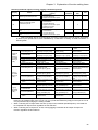
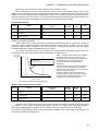
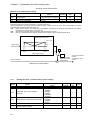
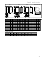
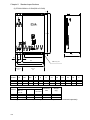
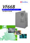
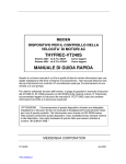
(4)
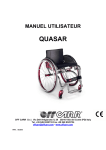
Securing of cooling space
When installing ED64A inverter main unit and DCL (DC reactor), keep cooling spaces as
shown in the following figure.
If there are heat sources around the inverter, arrange them appropriately so that the heat
does not affect the cooling of the unit.
When ED64A inverter is installed in a control panel, ventilate the panel to keep the
temperature in the panel within 50C. (If the ambient temperature is high, the reliability of
the inverter will be degraded.)
DCL
Inverter unit
30 cm or more
40 cm or more
Exhaust
30 cm or more
10 cm or more
(5)
1-5.
30 cm or more
10 cm or more
20 cm or more
30 cm or more
30 cm or more
Suction air
Cautions
The DC reactor (DCL) can become hot (may become over 100C). Keep a sufficient
distance from other devices.
Surely exhaust the heat generated by the inverter and DCL to the outside of the panel.
Prevent the exhaust from the inverter to circulate in the panel.
If a dynamic braking unit is used, install the resistor on the outside of the panel as
possible.
Avoid using the inverter in a considerably coarse environment.
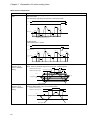
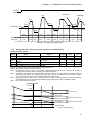
Cautions when wiring
(1)
Input the predetermined voltage to the inverter input terminal.
If 400V is input to a 200V class inverter, the inverter will be damaged.
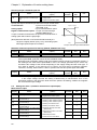
(2)
IGBT is used as inverter elements, and the inverter is operated at a high frequency.
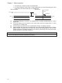
Therefore, it generates much noise. When wiring the inverter, pay attention to the following
points.
Lay the main circuit wires and the control signal wires apart from each other. If they are
laid in parallel, lay them at a distance of 30 cm or more.
9
Chapter 1
Before operation
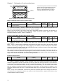
If the wires are crossed, lay them in perpendicular.
To prevent influence of the noise on other equipments, we recommend laying the main
circuit wires in a steel conduit pipe or a metallic pipe.
When laid in parallel
When crossed
Control signal
wires
Control signal
wires
At right angle
30 cm or more
Main circuit
wires
(3)
(4)
(5)
(6)
Main circuit
wires
To prevent interference by noise, use shielded wires or twisted shielded wires for control
signal wires.
To set the speed from the outside of the control panel, house the signal wires in a steel
conduit pipe or a metallic pipe.
As for the main circuit wire size, see “Input/output of wiring” of Chapter4 section2.
When shielded wires are used for output wiring or the wiring length exceeds 300 m, and the
ED64A inverter is operated by a DC brake, the inverter may be damaged or may not work
owing to resonance of leakage capacitor of the inverter output wiring to the ground and input
power inductance. In this case, consult us.
Earth-leakage circuit breaker
ED64A inverter uses IGBT as main circuit elements. Large leakage current is caused by high carrier frequency.
Use an earth-leakage circuit breaker especially for the inverter.
10
Chapter 1
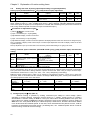
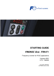
2.
Before operation
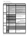
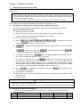
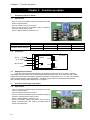
Connection
MCCB-F
86F
49F
FM
49B
Damping
resistor
VFDB2002
CN
CN
4 400Vclass:CN4,
CN Jumper
5
DBR
CN 200Vclass:CN5,
7
N
1 4 8 9
CN
7
8 8
Dynamic braking unit
(Option)
52MAX
P
PR
49B
DCL
DBR
(Note 5)
200
~
(Note 8)
400
~MCCB
230V
50/60Hz
460V
52M
+1
Noise filter
(Option)
+2
(Note 7)
52M
B
SET64-Z
R
U
S
V
T
W
MR
Noise filter
(Option)
EDM
(Note 4)
MT
TB2
CN2
PS
(Note 1)
P12
+15V
PS
ST-F
Reverse
run(START-F)
ST-R
7P-0.5SQ
(Note
Forward
jogging(JOG-F)
run(START-R)
JOG-F
Reverse
JOG-R
Emergency
jogging(JOG-R)
EMG
Reset(RESE
stop(EMG.STOP)
RESET
VFC2001-Z
PGB
3)GND
Z/U
V
z
W
―――――
GND
GND
CO-SPEV-SB(A)
PGA
Forward
T)
At ED64P mode (Mode 2)
TB2
(Note 3)
52MA
1
CN7
PG
2
3
86A
A
B
C
D
F
G
H
J
K
L
M
T
S
R
N
MS3106B-20-29
MS3057-12A
S
Inverter operation
TB1
Inverter operation contact
A
B
C
D
F
G
H
J
K
L
M
T
S
R
N
Inverter protection
4
5
Inverter protection contact
TB1
TB2
CN1
1
Rotational speed changer
10kΩ2W
(Note 1)
Multifunction input
and
Sequence input
Tachometer
Shield wire
F
0-10
(Note
4-20
A
3)GND
GND(Note 3)
N
Analog output
P
PS
MO1
PS
MO2
Multifunction output
and
PS
MO3
Sequence output
M-IN-1
MI1
MO4
DC24V 20mA Max
M-IN-2
MI2
M-IN-3
MI3
COM
(Note 3)
COM
M-IN-4
MI4
M-IN-5
MI5
M-IN-6
MI6
VFC64TB-Z
GND
GND
(Note 3)
(Note 1) Control input terminal (ST-F to RESET) and multi-function input terminal are able to do GND common input (sink
input). In this case, detach the jumper pin of the VFC2001-Z-control PCB from [CN_SO] and attach to [CN_SI]. These are
set to PS common input [source input] at the point of shipment.
(Note 2) PG is only for ED64P (with UVWAB-PG) mode, ED64V (with ABZ-PG) mode, the drawing above shows connection of
ED64P mode. When using ED64V mode, see the separate drawing given.
(Note 3) Never earth the GND and COM terminals of the control circuit.
(Note 4) The AC power terminals (MR and MT) for control circuit are provided on inverters of model 1122 and1144 or over.
(Normally, it is unnecessary to connect the terminal to power source. It will be connected only when action like protection
display is necessity without main circuit power.)
(Note 5) On 200V class inverters of model 1122 or lower and 400V class inverters of model 1544 or lower, the terminals 1 and
2 are short-circuited (when DCL is not used).
(Note 6) When the thermal relay of the brake resistance (DBR) functions, disconnect the inverter input power.
(Note 7) Install the main circuit contactor (52M) according to your conditions of use. ED motor generates voltage from the motor
itself when the motor is rotating while the inverter is stopped, so for your safety, we recommend installing contactor to the
output side. In this case, output side contactor will open/close from the 52M relay of the inverter.
(Note 8) When installing the main circuit contactor (52M) on the inverter input side, wait at least 10 minutes from reapplying power.
11
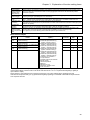
Chapter 1
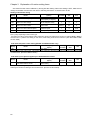
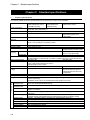
3.
Before operation
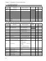
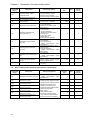
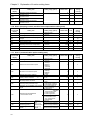
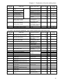
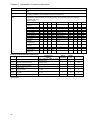
Terminal block and specifications
Terminal
No.
Device
VFC2001-Z
terminal block
TB 2
VFC2001-Z
terminal block
TB1
VFC64TB-Z
terminal block
TB1
Description
R·S·T
AC input
Connect to AC power.
U·V·W
Inverter output
Connect to ED motor.
1
For connection of DCL on +side
On inverters of model ED64A-1122 and model ED64A1544 or less without DCL, 1 and 2 are short-circuited.
2
For connection of DCL on -side and
dynamic brake resistor (thermal relay)
connecter. Or for +side input of sine
wave converter use.
B
For dynamic brake resistor (thermal
relay) connecter
For connection of DB unit. Or for –side
input of sine wave converter use.
Main circuit
Control circuit
Use
Dynamic brake resistor, thermal relay connecting terminal
+Terminal when using sine wave converter.
Collector terminal for built-in dynamic braking transistor
of ED64A-1122 and ED64A-1544 or less.
Connecting terminal between N terminal of the dynamic
braking unit (DB unit)
-Terminal when using sine wave converter.
Earth
Connect to the earth. When a noise filter (NF) is used,
connect to the earth terminal of NF.
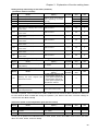
MR, MT
Control circuit power input (AC)
Provided to capacity of types ED64A-1122, ED64A1144 or more. (Can be operated without connecting. Use
these terminals to do protection indication when the main
circuit input is closed.)
PS
External signal power supply (+15v)
ST-F
Forward running signal
ST-R
Reverse running signal
JOG-F
Forward jogging signal
JOG-R
Reverse jogging signal
EMG
Emergency stop signal
RESET
Reset signal
GND
External signal power supply (0v)
P12
Power source for PG(+12v)
GND
Power source for PG(0v)
PGA
A-phase signal for PG
PGB
B-phase signal for PG
Z/U
U-phase signal for PG (Z-phase signal
at ED64V)
V
V-phase signal for PG
W
W-phase signal for PG
1,2
Contact output of running
3,4,5
Contact output of the protective
indication.
1
Power source for speed setting (+10V)
Use 10kΩ dial for speed command
0-10
Speed command voltage input
Input impedance 150kΩ
GND
Speed setting power source (0V)
Never earth this terminal
4-20
4-20mA speed command input
Input resistance 250Ω
PS
External signal power supply (+15V)
Max. output current (18mA)
GND
External signal power supply (0V)
Never earth this terminal
Input terminal (input current 3mA) for inverter control
signal and multi-functional input.
Or for input terminal of sequence function.
Connect to PG (A,B,U,V,W phase (ED64p mode) / A,B,Z
phase mode (ED64V mode))
Recommendable cable : Twist pair shield wire
CO-SPEV-SB (A) 7p-0.5SQ
(Products of Hitachi Cable Co.)
(Note 1) For connecting to the PG of ED motor, option of
straight plug (MS3106B-20-29S) and cable
clamp (MS30570-12A) (products of JAE) are
necessary.
Operate when inverter is running (52MA :contact 1A,
AC230V 0.5A)
Operate when protective operation of the inverter. (86A:
contact 1C, AC230V 0.5A)
[Close] between 4 to 3, [Open] between 4 to 5 during
protective operation
MI1
MI2
MI3
MI4
MI5
MI6
12
For input signal for multi-function input
and sequence function
Max. input voltage DC24V
Max. input current 3mA
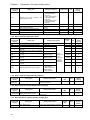
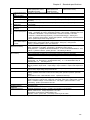
Chapter 1
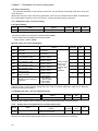
Terminal
No.
Device
Use
Before operation
Description
P
Connect P terminal to external power source (DC)
MO1
Terminals MO1 to MO4 are open collector output
Max. voltage DC24V / Max. current 20mA
MO2
MO3
For output signal for multi-function
output and sequence function
MO4
COM terminal is emitter common terminal of open
collector output.
COM
(Recommendable relay for multi-function output :
OMRON G7T-112-DC24V)
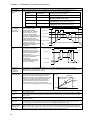
F
Output waveform
1ms
VFC64TB-Z
10V
Terminal block
TB2
For output frequency meter,
tachometer or divide frequency of PG
output. (Measure by DC voltmeter or
digital counter)
1/(6・f)
f : Frequency conversion value of rotation speed
DC voltage is DC3.6V / 60 Hz ( at top ≦120Hz)
1/2 or 1/4 when selecting PG output.
Divide frequency of PG pulse output ( Duty 1:1)
Max output current 5mA
(For more detail see Chapter 3 setting item G-09)
A
For analog output
Output voltage 0~±10V
GND
For 0V signal of terminal F,A
Never earth 0V terminal of F,A terminals
Max. output current 1mA
13
Chapter 2
Operation of ED64A
Chapter 2
1.
Checking before operation
1-1.
Control mode
Operation of ED64A
ED64A inverter has the following three modes.
(1)
With PG which has 5 signals (A, B, U, V and W phase) for speed/magnetic pole position
sensor. (ED64P mode)
(2)
With PG which has 3 signals (A, B and Z phase) for speed sensor. (ED64V mode)
(3)
Without speed sensor. (ED64S mode)
Conforming to the specification of the ED motor, select and use the most suitable control
mode. The selected control mode can be checked on the console display when power is turned on
or by the setting item S-01. Also, our ED motor uses A, B, U, V and W phase PG for speed/position
sensor. So, usually “ED64P mode” for with sensor and “ED64S mode” for without sensor is used.
“ED64V mode” is for particular use.
Note) Normally control mode is set to the one indicated at ordering when shipping. If you want to
change control mode, look section 6 “Changing inverter control mode” of Chapter2.
1-2.
Auto-tuning
Sense ED motor has permanent magnet built-in, electrical constant of the motor and
magnetic pole position (d-axis position) are necessary. ED64A is provided with an auto-tuning
function to measure these data and automatically set them in the parameters. Perform auto-tuning
before starting ED64A operation. (As for the auto-tuning procedures, see 4 “Auto-tuning” in Chapter
2.)
!
Safety precautions
・
Perform “auto- tuning” surely before operating, even when in case of changing combination of ED64A and
ED motor. Magnetic pole position (d-axis) will change according to the mounting position of PG, even with ED
motor of same type.
・
Perform “auto-tuning” surely before restarting, after PG of ED motor is exchanged. In case of having difficulty
in separating load machine from the motor, perform “d-axis measurement auto-tuning”.
・
If the magnetic pole position parameter of inverter and ED motor is corresponding, it may rotate in
unexpected direction. Please be careful.
1-3.
Changing rotation direction
ED motor runs in CW direction (clockwise when viewed from anti-transmission side) with
normal running command. To run in CCW direction (counterclockwise when viewed from antitransmission side) with normal running command, switch the motor wires connected to the phase V
and W. At ED64P and ED64V mode, additional to the signals V, W of PG, signals A and B also
need to be exchanged.
Because magnet (d-axis) position viewed from inverter change when rotation direction is
changed, A-30 (d-axis position) must be set again. Normally perform d-axis measurement autotuning described in section 4 “Auto-tuning” in Chapter 2. In case of having difficulty in performing
auto-tuning, calculate A-30 setting at the point of rotation direction change by the following
expression and set. (There is no necessity resetting A-30 at ED64S mode)
ED64P mode:
A-30 setting =[A-07 (PG pulse count) setting] / [A-06 (motor pole count) setting]×4 - [setting of
A-30 before change]
Add [A-07 (PG pulse count) setting] / [A-06 (motor pole count) setting]×8 if the value became
negative.
ED64V mode:
A-30 setting=[A-07 (PG pulse count) setting] / [A-06 (motor pole count) setting]×8 - [setting of
A-30 before change]
14
Chapter 2
Operation of ED64A
(Replace A-06 to L-05, A-07 to L-06 and A-30 to L-21 when using the 2nd motor)
1-4.
Replacing control PCB VFC2001-Z to spare parts
To make the new PCB applicable to the presently used inverter, it is necessary to set the
inverter capacity, motor rating (shown on the nameplate) and auto-tuning data and adjust the gains
at the analog circuit points, such as the center block DC voltage detecting point. (See section 7
“Operation when replacing PCB” of Chapter 2.)
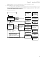
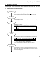
1-5.
Operations and outline
Confirmation of control mode, capacity
and voltage
Auto-tuning
operation
See 4 in Chapter 2.
Replacement of
VFC2001-Z
(control PCB)
See 6 in Chapter 2.
Power-ON
Turning on DIP switch
SW1-7
Power-on
Example of display
Display of ED64A control
mode, capacity and voltage
ED64S mode
250 kW 440V class
As for the operations on SET64, see Section 3 in
Chapter 2.
Monitor
(MONI)/operation
(OPR) mode
Press the FNC
key.
Press the
MONI.OPR key
Press the
STOP.RESET
switch.
Function (FNC) mode
Setting of motor
ratings
Power-OFF
Basic setting items
Power-ON
Inverter capacity
setting
Adjustment of voltage
detection gain
Expanded function
setting items
Turning on DIP switch
SW1-6
Occurrence of
failure
Occurrence of
failure
Power-OFF
Power-ON
Protective operation display mode
Turning off DIP switch
SW1-7
Display of protective operation
Display of data traced back one point
Start of auto-tuning
Copy of set data of
previous PCB
15
Chapter 2
Operation of ED64A
2.
Switches and LEDs on control PCB (VFC2001-Z)
2-1.
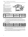
Functions of DIP switch SW1
To initialize the memory, set the capacity of the inverter to be used and perform auto-tuning,
it is necessary to operate the DIP switch SW1. The functions of the DIP switch SW1 are listed in
the following table.
DIP switch
OFF
Setting data cannot be written.
Setting data can be written.
SW1-2
Clear the data on failures and protective operations
in the past (protection history, data traced back one
point and traced-back data).
Normal
SW1-3
Not used
Normal
SW1-4
Changing control mode (ED64P, ED64V, ED64S)
Normal
SW1-5
DC mode auto-tuning or d-axis auto-tuning when
both SW1-5 and SW1-6 ON.
Full mode auto-tuning when SW1-5:OFF,SW1-6:ON
Normal operation
SW1-7
Initialization of set data and setting of inverter
capacity
Normal operation
SW1-8
Monitor mode for adjustment by us (Normally, do not
turn on this toggle.)
Normal
SW1-6
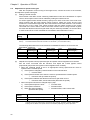
2-2.
ON
SW1-1
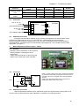
About confirm LED of CPU operation
VFC2001-Z is provided with LED lamp (LED1) to confirm state and power of CPU.
State of LED1
2-3.
Power/operation state of CPU
Flash about every 1 second
CPU in normal operation
Continuously on
Writing flash memory (HC / Sequence function),or CPU in abnormal operation.
Continuously off
CPU power off, or CPU in abnormal operation
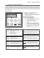
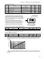
Mounting position of DIP switch and confirmation LED of CPU operation
Take off front cover of ED64A inverter,
open the mounting board of standard
console (SET64-Z) and you will find the
control PCB VFC2001-Z.
DIP switch (SW1) and confirmation
LED of CPU operation are mounted on
this VFC2001-Z PCB as shown on the
picture.
Confirmation LED for CPU operation
LED1 (green)
Control PCB
VFC2001-Z
DIP switch
SW 1
ON
OFF 1
PCB
VFC64TB-Z
or
Option PCB
16
8
Chapter 2
3.
Operation of ED64A
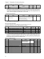
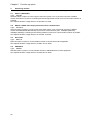
Functions of console panel (SET64-Z)
ED64A is standard provided with a console panel (SET64-Z) with a 5-digit LED indicator, eight
operation key buttons, unit LEDs and status indicating LEDs. With the console, you can operate the
inverter, read and write various functions setting data, monitor the operation status, display the details of
operations of protective devices, trace the data one point back and read the protective operation history
data. In addition, the console panel is used to initialize the inverter memory, set the inverter capacity and
start the auto-tuning.
Panel front face
Display of characters and numbers
r/min
Operation monitor and display of function code (number),
selected function and set data, protective operation and
protective operation history
Hz
A
V
FNC
REV
RUN
DIR
MRH
JOG
MONI
OPR
FNC
SET
LED display: 7-segment 5-digit display
FOR
Display of unit (LED display)
Display of status (LED display)
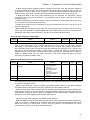
FNC:
On when the FUNCTION mode (function setting
mode) has been selected.
DIR:
On when any of the START and JOG keys on the
console panel has been selected
REV:
On when REV (reverse rotation) has been
selected.
START
REV
JOG
STOP
RESET
MRH: On when MRH has been selected. (MRH function
is used to accelerate or decelerate during the
operation by ↑,↓keys or from external connect)
RUN:
On while the inverter is running (flashing while the
inverter is decelerating to stop or the DC brake is
being applied).
JOG:
On while the inverter is jogging (also RUN is on).
Operation keys
SET
< In FUNC (function setting) mode >
< In FUNC (function setting) mode >
To enter the selected setting item number
To increment the number at the current digit by one
when the setting item number is selected or data is
set
< In MONI · OPR (monitor · operation) mode >
To write the set data
< In MONI · OPR (monitor · operation) mode >
To switch the monitor item
< Upon protective operation >
To read data traced one point back
The console has been set by speed command
setting site to accelerate with this key, at MRH mode
starts,
< In FUNC (function setting) mode >
MONI
OPR
FNC
To decrement the number at the current digit by one
when the setting item number is selected or data is
set
< In MONI · OPR (monitor · operation) mode >
Switching between MONI · OPR mode and FUNC mode
< In FUNC (function setting) mode >
To switch to the MONI · OPR mode
< In MONI · OPR (monitor · operation) mode >
To switch to the FUNC mode
The console has been set by speed command
setting site to decelerate with this key, at MRH mode
< In FUNC (function setting) mode >
< In MONI · OPR (monitor · operation) mode >
FOR
REV
To switch the normal rotation and reverse rotation
commands when START or JOG on the console
panel is effective (“REV” LED is turned on when the
reverse rotation command is selected)
JOG
< In MONI · OPR (monitor · operation) mode >
START
To run the inverter when the console has been
selected as the operation command setting site
To shift the selected digit one place to the right.
< In MONI · OPR (monitor · operation) mode >
STOP
RESET
To operate the inverter when the console has been
selected as the jogging command setting site
To stop the inverter when it has been started by the
START key on the console panel.
To reset the protective device under operation
17
Chapter 2
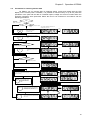
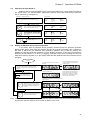
3-1.
Operation of ED64A
Procedures for reading and writing function setting data
For ED64A, fundamental setting items and functional setting items are prepared. The
fundamental setting items include setting items necessary for individual operation of the inverter.
The functional setting items are classified according to operation type into the areas A to S. The
data of the fundamental setting items and functional setting items are read and written in
accordance with the following procedures.
(The list of the functional setting items is given in Chapter 3.)
Start
MONI
OPR
FNC
Press the MONI · OPR/FUNC key
to switch the mode to the FUNC
(function setting) mode (LED-FNC
is turned on).
Expanded setting item
Do you want to set a basic
setting item?
Basic setting item
Select the item to be set with
the and keys.
Select “Func” with the and
keys.
SET
Move to the expanded setting
item area with the SET key.
If you press the SET key while “Fund” is displayed,
“Func” will be displayed, and the display will return to
the basic setting item area.
Select an expanded setting
item area from A to S with the
and keys.
Shift the highlight to the right
with the key, and set the
item number with the and
keys.
JOG
In the case of numeric data
SET
In the case of selection of option
Enter the function setting item
with the SET key.
The currently set data is displayed.
(The digit to be set flashes.)
Only data reading
Do you want to write
the data?
Correcting and writing of data
Select an option with the and keys.
Shift the highlight to the right
with the key, and set the
data with the and keys.
JOG
Data cannot be written in the
following cases.
To set a negative value, set “-” at the leftmost
digit. (The character at the leftmost digit
changes to “0” “1” … “9” “- (minus)”
“0.”)
SET
MONI
OPR
FNC
18
(When the data is out of the setting range)
Enter the set data with the SET
key to write it in the inverter.
(When the data is lower than the setting range
lower limit)
[Press the MONI · OPR/FUNC
key to return the mode to the
MONI · OPR (monitor ·
operation) mode.
(Rewriting is prohibited when writing is prohibited
or during operation.)
Chapter 2
3-2.
Operation of ED64A
Procedures for selecting monitor data
On ED64A, you can monitor data on rotational speed, current and voltage with the LED
display on the console panel. In addition, it is possible to read the history of up to five protective
operations in the past and the data on rotational speed, voltage and current recorded when the
protective operations were performed. Select the item to be monitored in accordance with the
following procedures.
Start
When FNC
(LED) is off
(MONI · OPR mode)
Check FNC
(LED).
When FNC (LED) is on (FNC
mode)
The currently selected monitor item is
displayed for 1 second.
The monitor data is displayed.
After
1 second
Press the MONI · OPR/FNC
key to set the inverter to the
MONI · OPR (monitor ·
operation) mode.
MONI
OPR
FNC
Press the SET key to display
the currently selected monitor
item.
SET
Every pressing the SET key switches the item.
(Protective operation history)
SET key operation
When the SET key is held
down for 1 sec
SET
Press the SET key once, and
the monitor item will be
switched to the next monitor
item.
Protective operation
history
Protective operation history?
Not protective operation
history
Normal monitor display
The data on the selected item is displayed.
Protective operation history item display
After
1 second
Up to five protective operations in the past are displayed
successively every 1 second. (The first numbers show the order
in which the protective devices operated. “1” is the earliest
operation number.)
After
1 second
When there are no protective operation
data
After
1 second
Press the SET key (for less
than 3 seconds), and the
display will return to the
monitor item selection
mode.
SET
Display of protective operation history data
Display of protective operation data item
SET
Press the SET key for 3 seconds or
more while the protective operation
whose data must be read is displayed.
(Six data items and data are displayed
successively every 1 second.)
Data upon protective operation
After
1 second
After 1 second
After 1 second
SET
Press the SET key, and the display will
return to the protective operation history
item mode.
After
1 second
19
Chapter 2
Operation of ED64A
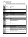
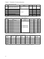
(List of selectable monitor display items)
Monitored data
Displayed
code
Motor rotational
speed
Rotational speed
set value
Units
Remarks
r/min
Display motor speed. (Calculation speed at ED64S mode)
r/min
Display rotational speed set value before acceleration/
deceleration control.
Output current
A
Display effective value of output current.
Torque command
%
Display torque command to be input to the torque controller after
limit processing.
DC voltage
V
Display voltage on the DC block.
Output voltage
V
Effective value of voltage between output wires.
Output frequency
Hz
Display output frequency.
Overload counter
%
Display overload (OL) or over-torque. Protective operation when
the value reaches 100%.
Display line speed, with ratio of setting value (n-00) at top
rotational speed.
m/min
Line speed
Motor temperature
℃
Able to display only when option unit T/61V is mounted.
Input terminal
check1
Input terminal
check2
Input terminal
check3
Output terminal
check1
Output terminal
check2
Main unit program
version
―
Display terminal state of
JOG-R,JOG-F,ST-R,ST-F
Display terminal state of
MI2,MI1,RESET,EMG
Display terminal state of
MI6,MI5,MI4,MI3
Display operational state of
86A and 52MA relays
Display output state of
MO4,MO3,MO2,MO1
―
Display version of the main unit. (ex: ED64-02-A1---H02A1)
Sequence version
―
Super-block version
―
Monitor for analog
gain adjustment
Special monitor for
adjustment
Protective operation
history display
―
Display date of the sequence ladder
(Months display:
execution. (ex: 2007-09-28---H7928)
Oct..---A, Nov.---B,
Display date of the Super-block
Dec.---C)
execution. (ex: 2007-10-02---H7A02)
Display detected value of voltage input during the adjustment of
analog input.
―
―
―
―
ST-F,EMG,MI3,52MA,MO1
ST-R,RESET,MI4,86A,MO2
JOG-F,M11,MI5,MO3
JOG-R,M12,MI6,MO4
Non-use
0:OFF/1:ON
―
(Special monitor for adjustment for us)
―
Readout history of five protective operations in the past and of the
data when the operated.
(List of data obtained upon execution of protective operations)
Monitor data
Rotational speed
command value
Motor rotational
speed
Display code
Unit
Remarks
r/min
Value after acceleration/deceleration control is displayed.
(Note that value differs from the one shown on the monitor)
r/min
Motor speed (calculation speed at ED64S mode)
Output current
Note)
A
Display max. current of 3 phase (absolute). (Note that value differs
from the one shown on the monitor. In case of sine wave,
approximate effective value can be obtained by dividing by 1.41)
Output voltage
V
Effective value of voltage between output wires
DC voltage
V
Voltage on DC block
Torque command
%
Torque command to be input to the torque controller after limit
processing is displayed.
Note)
20
Because the values are sampled at every calculation cycle and the current just before the execution protective operation is
displayed as the output current, if the current increases quickly owing to output short-circuiting, etc., the correct current
value at the occurrence of protective operation may not be displayed.
Chapter 2
3-3.
Operation of ED64A
Operation through SET64-Z
ED64A is able to running operate by the console panel (SET64-Z). The operating procedures
are shown below. (To operate ED64A, parameters must be set through auto-tuning in advance.
See 4 “Auto-tuning” of Chapter 2.)
Operations of console (SET64) keys
Set b-15 to b-18 to specify the console (SET64) as the running
command or jogging selection site. (DIR-LED is turned on.)
MONI
OPR
FNC
FOR
REV
Press the MONI · OPR/FNC key to set the
inverter to the MONI · OPR (monitor · operation)
mode. (When the inverter is set to the MONI ·
OPR mode, the FNC-LED is turned off.)
[Select the normal/reverse rotation command
with the FOR/REV key. (When REV-LED is
on, the motor will rotate in the reverse direction.
When the LED is off, the motor will rotate in the
normal direction.)
JOG
START
3-4.
Press the START key, and the motor
will start. Press the JOG key, and
the motor will jog.
Display of LEDs
FNC
REV
RUN
DIR
MRH
JOG
FNC
REV
RUN
DIR
MRH
JOG
FNC
REV
RUN
DIR
MRH
JOG
FNC
REV
RUN
DIR
MRH
JOG
Display on SET64-Z upon protective operation
In any mode, when a protective device operates, SET64-Z enters the protective operation
display mode. When some protective devices operate, the protective operations are numbered in
the order in which they are detected. Each protective operation can be reset by pressing the
RESET key while the protective operation is on the display. (However, it cannot be reset while the
protection is kept effective or a running or jogging command is kept input.) Pressing the SET key
while the protective operation is on the display reads the data obtained when the protective device
operated.
Occurrence of protective
operation
When some protective devices operate, the
protective operations are numbered and
displayed in order.
The protective operation that has occurred is
displayed.
After
1 sec
The protective operation is displayed.
When some protective devices operate, the protective
operations are numbered in the order in which they are
detected.
The protective operation can be reset by
turning on RESET on the terminal block. If
only a power failure has occurred and the
relay 86A has not operated, the protective
operation will be automatically reset when
the running command is turned off.
Display in monitor mode
If the protective operation
is reset by the RESET key,
the display will return to
the monitor display mode.
STOP
RESET
Display of data obtained upon protective operation (one
point traced back)
Data obtained upon protective operation
Display of protective operation data item
SET
Press the SET key while a protective
operation is on the display, and the data
obtained upon occurrence of the protective
operation is displayed. (Six data items and
their data are displayed successively every
1 second.)
(Protective operation history)
After
1 sec
After 1 sec
After 1 sec
SET
Press the SET key while the data upon
occurrence of a protective operation is on
the display, and the display will return to the
protective operation display mode.
After
1 sec
Note) If the MONI · OPR/FNC key is pressed in the protective operation display mode, the console temporarily exits
the protective operation display mode and enters the MONI or FNC mode.
21
Chapter 2
3-5.
Operation of ED64A
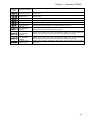
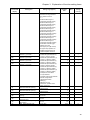
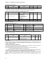
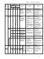
List of protective operations
A list of protective operations is given below. As for the processing upon occurrence of each
protective operation, see Chapter 7 “Maintenance.”
Protective
operation
code
Details of protective operation
Protective operation
Overcurrent
protection
IGBT(U) protection
Operates when the instantaneous value of output current is 3.6 times or more the
inverter rated value
Operates with IGBT over-current and fin overheating (less than 22kW or more than
75kW)
Operates with U phase IGBT over-current and fin overheating (30kW to 65kW)
IGBT(V) protection
Operates with V phase IGBT over-current and fin overheating (30kW to 65kW)
IGBT(W) protection
Overvoltage on DC
block
Operates with W phase IGBT over-current and fin overheating (30kW to 65kW)
Protects when the DC block voltage exceeds 400V (200V class) or 800V (400V
class).
Protects when output current effect value is kept higher than 150% of motor rated
value for a minute.
Operates when fuse of DC block blows out
Operates when motor does not start over 10 seconds after a running or jogging
command is input.
Operates when the motor speed exceed (forward or reverse) setting speed. (only at
vector control mode)
IGBT protection
Overload protection
DC fuse blowout
Starting failure
Overspeed
protection
Voltage down
(under voltage)
Overtorque
protection
Unit overheat
Protects when output torque is 150% of the rated torque for 1minute (when
over-torque protective operation is ON)
Operates when fin in the output block overheats (only over 75kw)
Memory trouble
Sum of setting data in EEPROM is not same (check when turning the power on)
Option error
Communication
time-out error
Operates when error happens to communicational option (J-00) when it is ON
Communication error occur between communicational option and master station
(time-out)
Operates when deviation of motor speed and command value (speed control input)
exceeds the setting (console setting) with speed control error detection (F-08) is ON
Operates when the motor temperature exceeds 150℃ while T/V61V option is in use
and motor overheat protection (F-12) is ON
Speed control error
Motor overheating
Parallel slave
trouble
FCL operation
Setting error 0
Setting error 1
Setting error 2
Setting error 3
PG (phase) error 1
PG (phase) error 2
PG (phase) error 3
PG (phase) error 4
PG (phase) error 5
PG (phase) error 6
22
Operates when DC voltage goes below 180V(200Vclass)/360V(400Vclass)
Operates when trouble (over-current etc.) occur to slave unit of parallel machine.
Operates when flash current limiter (FCL) continue for 10 seconds (2 seconds near
0Hz)
Operates when running/jogging or auto-tuning command is input to an improper
motor rating state.
Operates when running/jogging command is input to an improper PG pulse setting,
vector control (motor constant), or current control setting state. (Starting without
auto-tuning etc.)
Operates when running/jogging command is input to speed control-related setting
such as over-speed, MRH upper/lower limitspeed in improper state.
Operates when running/jogging command is input to analog input/output gain
related setting in improper state.
Operates when error of U, V, W signals of PG are detected at ED64P mode.
Operates when connection error of U, V, W signals of PG are detected at ED64P
mode.
Operates when reverse direction connection of phase sequence of U, V, W signals
and A, B signals of PG are detected at ED64P mode.
Operates when there is no change for the U, V, W signals of PG for rotation of more
than a period at ED64P mode, or no Z signal input for more than a rotation at
ED64V mode, after input of power source.
Operates when state that the connection of A, B signals and motor rotational
direction is reversed is detected during auto-tuning, at ED64P and ED64V mode.
Operates when there is internal phase calculation error according to the
misconnection of U, V, W signals or miss setting of d-axis position setting (A-30) at
ED64P and ED64V mode.
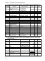
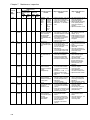
Chapter 2
Protective
operation
code
Operation of ED64A
Details of protective operation
Protective operation
Starting error
without sensor
External failure1
Operates when there is internal phase calculation error at starting of ED64S and
ED64V mode
Operates when there is a failure of phase detection at starting of ED64S and
ED64V mode
Operates when external failure 1 of multi-function input is input.
External failure2
Operates when external failure 2 of multi-function input is input.
External failure3
Operates when external failure 3 of multi-function input is input.
External failure4
Console
communication
trouble1
Console
communication
trouble2
Console
communication
trouble3
Emergency stop
contact ON
Operates when external failure 4 of multi-function input is input.
PG (phase) error 7
Display when trouble occur with communication between the console (SET64-Z)
and the main unit (communication time-out error)
Display when trouble occur with communication between the console (SET64-Z)
and the main unit (communication sum check error (detect by console))
Display when trouble occur with communication between the console (SET64-Z)
and the main unit (communication sum check error (detect by main unit))
Display when operation command is input during the input contact of emergency
stop is ON.
23
Chapter 2
4.
Operation of ED64A
Auto-tuning
ED64A inverter needs information of motor (electric constant etc.) such as motor resistance and
inductance and magnetic pole position of permanent magnet to control. ED64 is provided with an
auto-tuning function that measures these parameters necessary for operation and automatically set the
parameters. If these parameters necessary to operate the motor have not been set in ED64A, you must
perform the auto-tuning to set the parameters. Either of the following auto-tuning modes can be selected.
* Full-mode auto-tuning:
All necessary parameters are measured.
* DC-mode auto-tuning:
Only the primary resistance and dead time are measured.
* D-axis measurement auto-tuning: Measure only pole (d-axis)
Select the optimum auto-tuning mode in accordance with the following procedures.
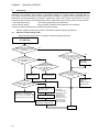
4-1.
Selection of auto-tuning mode
Select the auto-tuning mode in accordance with the following flowchart.
When operating/replacing
new ED motor
Yes
Has the full-mode auto-tuning
been done with motor to be
operated?
No
Can the motor be
disconnected from the
machine?
Has the wiring length
between the motor and the inverter been
changed considerably after the
auto-tuning?
Yes
No
No
DC-mode
auto-tuning
Is it impossible to
disconnect minor loads,
such as reduction
gears?
No
Yes
Full-mode autotuning without load
Full-mode autotuning with load
Has the motor rotation
direction been changed by changing of contact
of U, V, and W on the main circuit after
auto-tuning?
No
Are there
parameters obtained by tuning of
another motor of same
type?
No
Set the parameters A-17 to
A-33(except A-30) from the
data of other motor
DC-mode auto-tuning
d-axis measurement auto- tuning
(Unnecessary at ED64S mode)
Note) When
copying the data of
other motor, control
accuracy will
decline do to the
dispersion of the
motors. Disconnect
load machine as
much as possible,
at full-mode tuning.
Completio
n
24
Yes
d-axis autotuning
(Unnecessary at
ED64S mode)
Yes
Operation impossible
Consider how to disconnect the
motor from the machine and
perform the full-mode auto- tuning.
Yes
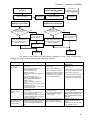
Chapter 2
When motor PG is
replaced
No
Perform the full-mode
auto-tuning in the same
manner as when a new ED
motor is operated.
d-axis auto-tuning
Completion
Replace inverter
(ED64A) to spare parts
Is there a record of
the parameters(A-17toA-33)
of previous inverter?
Auto-tuning is
unnecessary at change
of ED64P,V ED64S
When control mode is
changed (ED64S ED64V)
d-axis auto-tuning
Operation of ED64A
Completion
Replace control PCB
(VFC2001-Z) to spare parts
Is there a record of
the parameters(A-11toA-33)
of previous PCB?
Yes
Set the parameters
A-17 to A-33 from the
previous inverter.
Perform DC-mode
auto- tuning
Yes
No
Perform the full-mode
auto-tuning in the same
manner as when a new ED
motor is operated.
Set the parameters
A-11 to A-33 from the
previous inverter.
Completion
Completion
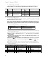
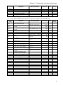
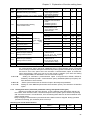
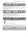
The following table shows the measurement parameters in each mode of auto-tuning,
conditions to perform, and operations during auto-tuning of ED64A.
Measurement
parameters
Condition to
perform autotuning
Motor operation
during auto-tuning
(in the case of
6-pole motor)
Full-mode auto-tuning
DC-mode auto-tuning
d-axis measurement
auto-tuning
Dead time compensation
(A-11 to 16)
Primary motor resistance (A-17)
d-axis inductance (A-18)
q-axis inductance (A-19)
Magnetic flux (A-20)
d-axis position (Magnet pole position)
(A-30)
d-axis pulse range (A-32)
d-axis pulse voltage range (A-33)
Magnetic pole decision method
selection (A-31)
Motor iron leakage conductance
(A-21)
Lq changing rate at 30 to 120% q-axis
current (A-22 to 25)
Lq changing rate at 30 to 120% d-axis
current (A-26 to 29)
Both motor rated values and PG pulse
count is set.
The ED motor to be measured must
be in a single unit state
disconnected from the load machine
(load for reduction gear is okay with
selecting “with load”).
After the motor rotates 2 times,
accelerated to about 80% of the rated
rotational speed. Normal direction
running without load. Selectable with
load.
Dead time compensation
(A-11 to 16)
Primary motor resistance (A-17)
d-axis position (Magnet pole
position) (A-30)
(When replacing the inverter
unit owning to a failure, copy the
parameters A-18 to 33 beside
the previous items by using PC
tool or console (SET64-Z))
(Parameters of A-11 to 29 and
A-31 to 33, beside the previous,
has to be set by previous)
Note) ED64A (without sensor)
mode dose not use this tuning.
(A-30 setting is unnecessary)
Both motor rated values and PG
pulse count is set.
Load machine is disconnected,
machine brake of the load
machine is off.
Both motor rated values and PG
pulse count is set.
The motor may rotate 2/3 time.
(720°at electrical degree).
Rotation direction is selectable.
Rotates up to 20°(60°at
electrical degree) at ED64P
mode.
Maximum motor axis will rotate
once at ED64V mode.
Perform full-mode automatic
measurement beforehand
and set data beside “d-axis
position”
25
Chapter 2
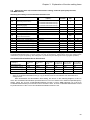
4-2.
Operation of ED64A
Preparation for auto-tuning
Before performing the auto-tuning, it is necessary to set the motor rated values (shown on the
motor nameplate) and the carrier frequency to be used in the following setting numbers. (As for the
setting procedures, see 3-1 “Procedures for reading/writing function setting data” in Chapter 2.)
NO.
Item
Setting range
No.
Item
Setting range
A-00
Max. rotational
speed
Min. rotational
speed
Motor rated
capacity
300 to 14700
A-04
40 to 150% of INV rated current
0 to max. rotational speed (A-00)
A-05
3 rank below the INV rated
capacity to INV rated capacity
140 to 230V (200Vclass)
280 to 460V (400Vclass)
A-06
Rated motor
current
Rated motor
rotational speed
Selection of
motor pole count
PG pulse count
PWM carrier
frequency
2.0 to 14.0kHz
A-01
A-02
A-03
Motor rated
voltage
A-07
A-08
67 to 100% of max. rotational speed
2 pole to 12 pole
60 to 3600 (unnecessary for ED64S)
(INV in the table refer to the rate of inverter used)
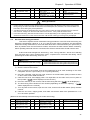
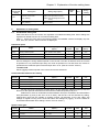
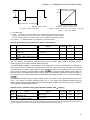
4-3.
Full-mode auto-tuning procedures
This section explains the full-mode auto-tuning procedures. Full-mode auto-tuning
measures all parameters from A-11 to A-33 automatically. Before performing the auto-tuning,
disconnect the motor from the load machine.
In case the reduction gear is not connectable owning to the motor with reduction gear etc.,
select ”full-mode auto-tuning with load”. (Only for small loads such as reduction gear. Disconnect
from load machine.) In this case, selection of rotation direction during auto-tuning is also possible.
Select the auto-tuning of the rotation direction set according to the reduction gear. (Normal
direction at normal operation)
Select auto-tuning with load at A-10 “Selection of tuning”
A-10
Item
Selecting tuning
(full-mode auto-tuning)
Setting range
0: Normal
1: Auto-tuning with load (normal run)
2: Auto-tuning with load (reverse run)
(Full-mode auto-tuning procedures)
1) Wire the motor (disconnected from the load machine) to the inverter. Wire the PG. (Wiring of PG
is unnecessary at ED64S mode.)
2) Turn on power to the inverter, and set the parameters A-00 to A-08 according to the motor
nameplate.
3) Select “0: Normal”,”1: With load (normal run)” or ”2: With load (reverse run)” to set to A-10
“Tuning selection”
4) Once turn off power, open the unit cover, and turn on the DIP switch (SW1) number 6 on the
inverter control PCB VFC2001-Z.
5) Close the unit cover, and reapply power. If an input MC is on the main circuit, turn on power to
the input MC. (“
” will be displayed on the console.)
6) Press the JOG key on the console, and the auto-tuning will start. (“
” will be displayed.)
7) The auto-tuning will finish in few minutes (depending on the motor capacity). (
” will be
displayed on the console.)
8) Turn off power to the inverter, open the unit cover, and turn off the DIP switch (SW1) number 6.
9) Close the unit cover, reapply power, and make sure that the data of the parameters A-11 to
A-33 have been updated.
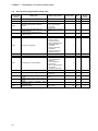
(Data to be automatically measured during full-mode auto-tuning)
No.
A-11
A-12
A-13
A-14
A-15
26
Item
Unit
No.
Dead time compensation
value (phase U, +side)
Dead time compensation
value (phase U, -side)
Dead time compensation
value (phase V, +side)
Dead time compensation
value (phase V, -side)
Dead time compensation
value (phase W, +side)
―
Item
A-19
Motor q-axis inductance
―
A-20
Motor magnetic flux
―
A-21
―
A-22
―
A-23
Motor iron loss
conductance
Lq changing rate at 30%
q-axis current
Lq changing rate at 60%
q-axis current
Unit
No.
Item
mH
A-27
Wb
A-28
mmho
A-29
%
A-30
%
A-31
Lq changing rate at 60% d-axis
current
Lq changing rate at 90% d-axis
current
Lq changing rate at 120%
d-axis current
d-axis position
(only for ED64P,V)
Selecting magnetic pole
decision mode without sensor
Unit
%
%
%
Chapter 2
No.
Item
No.
Item
―
A-24
Primary motor resistance
mΩ
A-25
Motor d-axis inductance
mH
A-26
Lq changing rate at 90%
q-axis current
Lq changing rate at 120%
q-axis current
Lq changing rate at 30%
d-axis current
A-16
Dead time compensation
value (phase W, -side)
A-17
A-18
Unit
Unit
Operation of ED64A
No.
%
A-32
%
A-33
Item
Unit
d-axis measurement pulse
width
d-axis measurement pulse
voltage amplitude
ms
%
Safety precautions
!
Perform the full-mode auto-tuning with the motor in the single unit state disconnected from the load machine.
During tuning, the motor will rotate at about 80% of the rated speed, and, therefore, can cause accidents. If it
has loads, correct tuning may not be performed.
Just after the start of the full-mode tuning, the motor does not rotate at a high speed because it is under DC
test. However, voltage is on the motor. Be careful not to touch it. It may cause an electric shock.
In the full-mode tuning, after the DC test for about 1 minute (depending on the capacity) at the start, the motor
will start. Be careful not to come close to the motor until the end of tuning (or a tuning error) is displayed.
4-4.
DC-mode auto-tuning procedures
This section explains the DC-mode auto-tuning procedures. In the DC-mode auto-tuning, the
dead time compensation values A-11 to A-17 and the motor primary resistance are automatically
measured. During measurement, motor will rotate about 2/3 in normal direction (at 6 pole motor). If
there is problem when the load machine rotates, disconnect the load machine before measuring.
Also if operating with load machine connected, take off the machine brake of load machine side.
At DC-mode auto-tuning/d-axis auto-tuning, A-32 “Tuning selection” will be item selecting
from DC-mode and d-axis measurement mode, compared from full-mode auto-tuning. When
performing DC-mode auto-tuning, set 0 to A-10.
Item
Selecting tuning
(DC-mode/d-axis mode auto- tuning)
A-10
Setting range
0: DC-mode auto-tuning
1: d-axis measurement auto-tuning with load (normal run)
2: d-axis measurement auto-tuning with load (reverse run)
(DC-mode auto-tuning procedures)
1)
Wire the motor to the inverter.
2)
Turn on power to the inverter, and set the parameters A-00 to A-08 according to the motor
nameplate. And set “0 (DC mode)” to A-10 (Tuning selection)
3)
Once turn off power, open the unit cover, and turn on the DIP switch (SW1) numbers 5 and 6
on the inverter control PCB VFC2001-Z.
4)
Close the unit cover, and reapply power. If an input MC is on the main circuit, turn on power to
the input MC. (“
” will be displayed on the console.)
5)
Press the JOG key on the console, and the auto-tuning will start. (“
6)
The auto-tuning will be finished in few minutes (depending on the motor capacity).
will be displayed on the console.)
7)
Turn off power to the inverter, open the unit cover, and turn off the DIP switch (SW1) numbers
5 and 6.
8)
Close the unit cover, reapply power, and make sure that the data of the parameters A-11 to
A-17 have been updated.
” will be displayed.)
(“
”
(Data to be automatically measured during DC-mode auto-tuning)
No.
Item
A-11
Dead time compensation
value (phase U, +side)
Dead time compensation
value (phase U, -side)
Dead time compensation
value (phase V, +side)
A-12
A-13
Unit
No.
Item
―
A-14
―
A-15
―
A-16
Dead time compensation
value (phase V, -side)
Dead time compensation
value (phase W, +side)
Dead time compensation
value (phase W, -side)
Unit
―
No.
Item
A-17
Primary motor resistance
Unit
mΩ
―
―
27
Chapter 2
Operation of ED64A
Data of A-18 to A-23 except for the data shown above must be set separately.
!
Safety precautions
In the DC-mode tuning, voltage is on the motor during DC test. It can cause an electric shock. Take care not
to touch it.
Even in the DC mode, the motor slowly rotates in normal direction. Pay attention to the machine for in case of
tuning with the load machine connected, load machine will also move.
4-5.
d-axis measurement auto-tuning procedure
This section explains the d-axis measurement auto-tuning procedures. D-axis measurement
auto-tuning measures only d-axis PG pulse of A-30. When auto-tuning, motor will rotate up to 20°
at ED64P mode (6 pole motor) and up to 360°at ED64V mode in normal or reverse direction.
(Direction is selectable at A-10) If there is problem when the load machine rotates, disconnect the
load machine before measuring. Also if operating with load machine connected, take off the
machine brake of load machine side. (Correct tuning cannot be done if the load machine does not
rotate)
At DC-mode auto-tuning/d-axis measurement auto-tuning, A-10 “Tuning selection” will be
item selecting from DC-mode and d-axis measurement mode, compared from full-mode
auto-tuning. When performing d-axis measurement auto-tuning, make A-10 to “1 (d-axis
measurement mode (normal))” or “2 (d-axis measurement mode (reverse))”. Because ED64S
(without sensor) mode does not use A-30 setting, d-axis measurement auto-tuning is not possible.
1)
2)
3)
4)
5)
6)
7)
8)
9)
(d-axis measurement auto-tuning procedures)
Wire the motor to the inverter.
Turn on power to the inverter, and confirm that parameters A-00 to A-08 of the motor rated
value etc., and previous auto-tuning value A-11 to A-33 (except for A-30) are set.
Set 1 or 2 (d-axis mode) to A-10 (auto-measuring mode)
Once turn off power, open the unit cover, and turn on the DIP switch (SW1) numbers 5 and 6
on the inverter control PCB VFC2001-Z.
Close the unit cover, and reapply power. If an input MC is on the main circuit, turn on power
to the input MC. (“
” will be displayed on the console.)
Press the JOG key on the console, and the auto-tuning will start. (“
” will be displayed.)
The auto-tuning will be finished in a minute (depending on the load machine). (“
” will be
displayed on the console.)
Turn off power to the inverter, open the unit cover, and turn off the DIP switch (SW1) numbers
5 and 6.
Close the unit cover, reapply power, and make sure that the data of the parameters A-30
have been updated.
(Data to be automatically measured during d-axis measurement auto-tuning)
No.
Item
Unit
A-30
d-axis position pulse
No.
Item
Unit
No.
Item
Unit
―
Data of A-11 to 29 and A-31 to 33 except for the data shown above has to be set beforehand.
!
Safety precautions
In the d-axis measurement tuning, voltage is on the motor. It can cause an electric shock. Take care not to
touch it.
Even in the d-axis measurement mode, the motor slowly rotates in normal direction. Pay attention to the
machine for in case of tuning with the load machine connected, load machine will also move.
4-6.
Troubles during auto-tuning
If any trouble occurs during tuning, the trouble is displayed on the console, and the inverter stops.
1)
When “
” is displayed
The setting of any of A-00 to A-08 may be improper. Review the settings, and redo the
tuning from the beginning.
28
Chapter 2
When “
code
to
2)
” and “
Operation of ED64A
” are displayed alternately. (The
part displays error
)
This indicates that a trouble occurred during tuning or the results of tuning are abnormal.
Check the inverter capacity setting, the settings of A-00 to A-08 and the wiring between the
inverter and the motor, and check that the motor is not locked by the brake and loads are not
connected to the motor (only in the full-mode). 2 digit number following Err is the error code.
See error code table below.
3)
When”
” is displayed. (
part will be
to
)
Input error from the PG. Check if there if any error to the wiring from PG, connection, PG
pulse count setting (A-07) and PG itself and then redo from the beginning. (Only for ED64P
and ED64V mode.)
4)
When another protection is displayed
This indicates that a protective device operated during auto-tuning. See “Chapter 7 Error!
The original of the reference is not found“ and remove the causes of the trouble. Then, redo
the tuning from the beginning.
(Table of error code at tuning failure)
Error code
01
Meaning of error
The motor cannot rotate during
auto-tuning
02
Data was not set at the DC test
03
Overflow occurred during calculation
of primary resistance
Overflow occurred as the result of
calculation of primary resistance
Overflow occurred at calculation of
dead time
Overflow at calculation of Lq or Lq
changing rate (30, 60, 90 or 120%)
Overflow at calculation of Ld or Ld
changing rate (30, 60, 90 or 120%)
d-axis pulse width setting or d-axis
pulse amplitude setting error
Overflow during calculation of iron
loss conductance
Motor is not accelerating
Pole direction determination cannot
be done by d-axis auto-tuning
No motor rotation by d-axis
auto-tuning
Others
1) STOP key is pressed during
auto-tuning
2) Under voltage during auto-tuning
3) Protective operation during
auto-tuning (this code is displayed
after the protective operation is reset)
04
11 to 16
20 to 24
30 to 34
40, 41
51
50
60
61
98
99
4-7.
Major check items
Is there no brake applied to the motor?
Is there no large load applied to the motor?
Is the PG connected properly?
Is the wired correct?
Is the rated current etc. set properly?
Is the adjustment of DC voltage done?
Is the matching of motor and inverter proper?
Is the setting of inverter capacity correct?
Is the matching of motor and inverter proper?
Is the rated current etc. set properly?
Is A-00~A-08 set correctly?
Is there no excessive load applied to the motor?
Is the motor not locked?
Is the PG correctly wired?
--Remove the cause of under voltage and
protective operation
Second motor auto-tuning (Only when using second motor function)
ED64A is provided with “second motor function” to operate 2 motors with 1 inverter. When
operating second motor, change all the wiring of PG and inverter-motor with contactor or relay etc.
shift to second motor by motor rate of internal inverter, memorized beforehand by multi-function
input function (see Chapter 3) .
At here, the procedure of auto-tuning of second motor is shown.
When using second motor function, turn on the L-00 second motor function selection, and set
second motor rate (shown on motor nameplate) to L-01 to L-08 of the following.
29
Chapter 2
Operation of ED64A
No.
Item
Setting range
No.
Item
Setting range
L-00
Selecting 2nd motor
use
2nd motor rated
capacity
OFF/ON
L-03
40 to 150% of INV rated current
3 rank bellow INV rated capacity to
INV rated capacity
140 to 230(200Vclass)
L-04
2nd motor rated
current
2nd motor rated
rotational speed
Selection of 2nd
motor pole count
2nd motor PG
pulse count
L-01
L-02
2nd motor rated
voltage
L-05
280 to 460(400Vclass)
L-06
67 to 100% of Max. rotational
speed
2 pole to 12 Pole
60 to 3600
(Unnecessary for
ED64S)
(Rated INV in the table refer to the rate of inverter used)
Layout “second motor select” to multi-function input terminal, and turn the terminal ON (see Chapter
3). Operate full-mode, DC-mode auto-tuning and d-axis measurement mode auto-tuning in this state just
as same as the direction of auto-tuning of the usual motor. Result of auto-tuning will be set to L-08 to
L-24 shown below, instead of setting of A-17 to A-33. (Dead time compensation value (A-11 to A-16) will
not be set at second motor auto-tuning, because it is inverter’s own data. Also use A-10 for the selection
of auto-tuning just as same as for normal motor.)
(Data to be automatically measured during second motor auto-tuning)
Unit
No.
2nd motor primary resistance
mΩ
2nd motor d-axis inductance
mΩ
2nd motor q-axis inductance
mH
2nd motor magnetic flux
mH
No.
Item
L-08
L-09
L-10
L-11
L-12
L-13
L-14
Item
2nd motor changing rate at 60% q-axis current
%
L-17
L-18
L-19
L-20
L-21
L-22
L-23
L-15
2nd motor changing rate at 90% q-axis current
%
L-24
L-16
2nd motor changing rate at 120% q-axis current
%
2nd motor iron loss conductance
%
2nd motor changing rate at 30% q-axis current
%
2nd motor changing rate at 30% d-axis current
%
2nd motor changing rate at 60% d-axis current
%
2nd motor changing rate at 90% d-axis current
%
2nd motor changing rate at 120% d-axis current
2nd motor d-axis position (ED64P, V mode only)
%
--
2nd motor pole determination mode without sensor
2nd motor d-axis measurement pulse width
2nd motor d-axis measurement pulse voltage
amplitude
At second motor auto-tuning display of the console would be ”
“
4-8.
”→”
” and “
”→”
Unit
”→”
-ms
--
”,
”
Display on console during auto-tuning
The following table shows the LED display on the console (SET64-Z) during auto-tuning.
LED display
30
Meaning of display
LED display
Meaning of display
Preparation for
Full-mode auto-tuning
Preparation for 2nd motor
d-axis measurement
auto-tuning
Preparation for DC-mode
auto-tuning
During auto-tuning
Preparation for d-axis
measurement auto-tuning
Normal termination of
auto-tuning
Preparation for second
motor full-mode
auto-tuning
Preparation for second
motor DC-mode
auto-tuning
Abnormal termination of
auto-tuning (failure)
(Display alternately)
Chapter 2
5.
Operation of ED64A
Procedures for test running
During test running, at first, test the motor in the disconnected state. After ensuring that the motor
operates normally, connect the motor to the machine, and adjust the speed control gain. This section
explains the procedures for test running using the console panel.
5-1.
Test running of motor in disconnected state
At first, test the motor in the disconnected state.
Preparation and
wiring
Connect the inverter and the power supply (R, S and T), and connect the inverter and the
motor (U, V and W). Connect earth wires to the earth terminals ( ), connect the DCL (if
necessary), and wire the inverter and the PG. (Wiring of PG is for ED64P, V mode only)
(See 2 “Connection” in Chapter 1.)
Auto-tuning
Set the maximum rotational speed (maximum frequency) and motor ratings (A-00 to A-10),
and perform the full-mode auto-tuning.
(See 4 “Auto-tuning” in Chapter 2.)
Setting of operation
site
Select the console panel (SET64-Z) as the running command and speed command operating
site. Set the items as shown below.
(Expanded setting items in area b) (The items are set as shown below before shipment.)
No.
Item
Setting
b-15
Selecting setting site in interlock mode
Set to 1 (console)
b-16
Selecting rotational speed command
setting site
Set to 0 (interlock)
b-17
Selecting speed command site
Set to 0 (interlock)
b-18
Selecting jogging command site
Set to 0 (interlock)
(See 3.1 “Procedures for reading and writing function setting data” in Chapter 2.)
Setting of speed
command and
acceleration /
deceleration time
Set an appropriate speed command and acceleration/deceleration time in the following items.
(Basic setting times)
No.
Item
Setting range
Unit
0.SrEF
Set rotational speed
-Max. rotational speed to max. rotational speed
r/min
3.Acc1
Acceleration time
0.0 to 3600.0
sec
4.Dec1
Deceleration time
0.0 to 3600.0
sec
Note) The acceleration/deceleration time is the time required to accelerate/decelerate from
0 to max. rotational speed / from max. rotational speed to 0.
(See 3.1 “Procedures for reading and writing function setting data” in Chapter 2.)
Start/stop
Press the MONI · OPR/FNC key to set the inverter to the MONI · OPR mode (FNC-LED is
turned off), and press the START key. The motor will be accelerated at the rate set in 3.Acc1
to the speed set in 0.SrEF. If the STOP key is pressed, the motor will be decelerated at the
rate set in 4.Dec1. (When 0 (free stop) has been specified in b-03, if the STOP key is pressed,
the motor will stop after free running.)
(See 3.3 “Operation through SET64-Z” in Chapter 2.)
31
Chapter 2
5-2.
Operation of ED64A
Adjustment of speed control gain
After the completion of test running of the single motor, connect the motor to the machine,
and adjust the speed control gain.
(1)
Setting of inertia moment
Since ED64A uses MFC control combining feedforward control and cancellation for speed
control, robust speed control can be realized by setting the inertia moment.
For 9.ASrJ (speed control inertia moment), specify 20 to 100% of the sum of the motor rotor
inertia moment and the load machine inertia moment. (When the motor and the load
machine are connected through belts, the inertia moment of the load machine is not included,
and the sum of the motor rotor inertia moment and the inertia moment of the pulley
connected to the motor shaft is used as the inertia moment. When a large number of gears
are used and abnormal noise from gear clash may be caused by backlash, set a lower value,
or set E-06 and E-07 to OFF to disable the cancellation and feedforward control.)
Fundamental
setting
Item
9.ASrJ
Speed control inertia moment
Setting range
Unit
0 to 65535
gm
2
2
Note 1)
9.ASrJ must be set in gm . Set the value obtained by multiplying the value determined in kgm2 by 1000.
Note 2)
The inertia moment must be set in 9.ASrJ. Do not set GD2. (1/4 of the value of GD2)
The following table shows the inertia moments of standard ED motors. As for motors not
listed below, contact us.
Type
EDM1711V
EDM1721V
EDM1911V
EDM2211V
(2)
Rotor inertia
2
moment (gm )
17
25
32
60
Type
EDM2221V
EDM2231V
EDM2721V
EDM2751V
Rotor inertia
2
moment (gm )
71
83
175
222
Type
EDM3111V
EDM3121V
EDM3131V
Rotor inertia
2
moment (gm )
313
393
470
Adjustment of speed control proportional gain and speed control integration time constant
Run the motor connected with the machine, and adjust the 7.ASrP (speed control
proportional gain) and 8.ASri (speed control integration time constant).
When the rotational speed is set to an appropriate running speed and the motor is
operated at the constant speed
1) If the speed is changed by load fluctuation on the load machine:
Increase ASrP.
2) If the speed fluctuates even when the motor is operated at the constant speed:
Decrease ASri (increase the speed).
3) If the speed oscillates and abnormal noise from gear clash occurs:
Decrease ASrP, and increase ASri (decrease the speed).
When the speed command is changed step by step
1)
2)
3)
Increase ASrP.
Decrease ASrP.
Decrease ASrP, and increase ASri
Fundamental
setting
Item
Setting range
Unit
7.ASrP
8.ASri
Speed control proportional gain
Speed control integration time constant
3 to 50
20 to 10000
ms
Note 1)
32
If the speed response is slow:
If the speed overshoots:
When the speed oscillates:
(decrease the speed).
Unlike in the case of normal PI control, when this control method is used, the apparent integration time
changes as the P gain (speed control proportional gain) changes. Therefore, normally, adjust ASrP
keeping ASri as default. If the speed cannot be controlled by adjusting only ASrP, adjust ASri.
Chapter 2
6.
Operation of ED64A
Changing inverter control mode
ED64A is installed with 3 modes: ED64P (with speed/magnetic pole position sensor) mode, ED64V
(with speed sensor) mode and ED64S (without speed/magnetic pole position sensor) mode. The mode
will be set to the specification of the ED motor of normal use.
Control mode can be changed by following 2 ways, in case when control mode different from the
requested is set or when the mode without sensor is needed owning to the failure of PG installed to the
ED motor.
(1)
Initialize the set data and change mode.
See (Memory initializing procedures) of 7-1 “Procedures for setting inverter capacity and DC
voltage detection gain.” and initialize the control mode you want to change.
This procedure suits when operating inverter in control mode different from set right now,
because initializes all the data. After the mode change, data setting and auto-tuning with the
new motor is necessary.
(2)
Change only the control mode with set data as present.
Operate the following “Operation of control change mode” of 6-1 and can change only the
control mode. When operating in this procedure, there will be no change to the data, except
for the ones that changes the range by the control mode change (note2). Result of
auto-tuning will also remain, so if the motor is same, auto-tuning is not needed. (But when
shifting to ED64P or ED64V mode after auto-tuning is done in ED64S mode, d-axis
measurement auto-tuning is needed because d-axis position is not set. Use this procedure
when changing from ED64S mode is needed owning to the failure of PG etc. (Note1, note2))
6-1
Operation of changing control mode
1) Turn OFF power of the inverter.
2)Remove the cover, turn on DIP switch (SW1)-4 on VFC2001-Z PCB.
3)Close the cover, and turn on power.
4)After
window,
is displayed in the display
flashes. Press [SET] key
is displayed. After selecting the mode to be used with ↑ and ↓ keys, press
the [SET] key.
5)
(
=without sensor mode,
=with speed sensor mode,
=with speed/magnetic pole position sensor mode )
6)
is displayed. This means the changing of control mode has been completed.
7)Turn OFF power of the inverter.
8)Remove the cover, and turn off the DIP switch (SW1)-4.
9)Close the cover.
Note 1) When shifting the mode to ED64S mode from ED64P or V mode, control accuracy of speed and toque,
response characteristics will deteriorate. Please be careful when using ED64P or V mode in need of
accuracy and response.
Note 2) Setting item written below will change the value when control mode changes.
Display
0.SrEF
A-01
A-10
E-08
E-09
G-09
Item
Setting rotational speed
Minimum rotational speed
Tuning selection
Starting speed at variable
structure proportional gain
Variable structure proportional
gain minimum ratio
6F output selection
ED64S⇔ED64V
To the initialized value
To the initialized value
To the initialized value
To the initialized value
ED64S⇔ED64P
To the initialized value
To the initialized value
To the initialized value
To the initialized value
ED64P⇔ED64V
No change
No change
To the initialized value
No change
To the initialized value
To the initialized value
No change
To the initialized value
To the initialized value
No change
33
Chapter 2
7.
Operation of ED64A
Operations after replacement of PCB
This section explains the operations to be performed after replacement of the control PCB
(VFC2001-Z).
・Induction motor drive inverter (VF64) and inverter for ED motor drive (ED64A) use same control
PCB (VFC2001-Z) but different control software is written inside. Control PCB for VF64A can not
be used to ED64A. (ED64A control PCB has soft version code ED64-XX-XX (XX-XX are number or
alphabet) on the surface of IC18)
・When ordering spare or replacement parts of control PCB, please designate “for ED64A”
When VFC2001-Z is individually delivered as a spare part, the parameters of the board are at initialized
value. Setting the parameters appropriately to the inverter are necessary in use.
7-1.
Procedures for setting inverter capacity and DC voltage detection gain
The inverter capacity and DC voltage detection gain can be set by initializing the memory.
(Memory initializing procedures)
1)
Turn OFF power to the inverter.
2)
Remove the cover, and turn on the DIP switch (SW1)-7 on the PCB VFC2001-Z.
Fit a DC voltmeter or a tester between terminal block 2 and.
3)
Close the cover, and turn on power.
4)
After “
window, “
5)
” is displayed in the display
” flashes. Press the SET key.
“
” is displayed. After selecting the mode to be used with the and keys, press
the SET key.
(“
” =without sensor mode, “
” =with speed sensor mode, “
= with speed/magnetic pole position sensor mode)
”
6)
The capacity is displayed like “
.” Set the capacity of ED64A to be used using the
and keys, and press the SET key to enter the capacity.
7)
The voltage is displayed such as “
.” Measure the current DC voltage, set the
measured DC voltage using the JOG/ key and and keys, and enter the value with the
SET key. Then, the DC voltage detection gain is calculated from the detected DC voltage
value and the set value, and the calculated gain is automatically set in S-00. (If the DC voltage
detection gain must be adjusted after initialization, adjust S-00 directly.)
8)
After “
” is displayed for several ten seconds, “
means the memory initialized.
9)
Turn off power to the inverter.
” is displayed. This
10) Remove the cover, and turn off the DIP switch (SW1)-7. Remove the DC voltmeter or tester
fitted in Step (2).
11) Close the cover.
!
Safety precautions
For measurement of DC voltage, use a DC voltmeter (or tester) that can measure voltage of 500 V or more
(200V class) or 1000 V or more (400V class).
High voltage is applied to the DC voltmeter (or tester). The voltage measurement shall be performed by electricians.
7-2.Adjusting external analog input gain
Setting items below are adjusting gain of analog input. See setting item area G of Chapter 3
before adjusting.
Display
G-00
G-01
34
Item
+ side adjusting gain of analog input
- side adjusting gain of analog input
Setting area
50.00 to 150.00
50.00 to 150.00
Initialize data
100.00
100.00
Unit
%
%
Chapter 3
Chapter 3
Explanation of function setting items
Explanation of function setting items
ED64A inverter can be operated by setting its functions on the standard console panel (SET64-Z).
The setting items for ED64A are classified into fundamental setting items and functional setting items.
The functional setting items are grouped into areas A to S according to function type as shown below to
facilitate invocation of the functions.
Classification
Area
Fundamental
setting items
Fund
Functional
setting items
A-xx
b-xx
c-xx
d-xx
Set rotational speed, jogging rotational
speed acceleration/deceleration time 1,2
speed control gain
Max. rotational speed, motor rate, motor
constant setting area
Operation mode and operation sequence
selection area
Setting area related to multi-function output
Acceleration/deceleration setting, rotation
speed jump function, MRH function
Remarks
Indispensable setting area
Set when selecting operation mode, HC
function, sequence function, operating site.
Set when using multi- function output
Set when using S-curve accel./decel., 3rd and
4th accel./decel., rotational speed jump, MRH
function
Set when using torque limit, torque command
characteristics and temperature compensation
function, cancellation and feedforword
functions off, adjust variable structure speed
control gain and current control gain.
E-xx
Setting area related to torque limit, torque
command characteristics, speed control,
vector control
F-xx
Setting area related to built-in DB
operation, protective function, trace-back
function
Set when using built-in DB, protective function
for over-speed, over-frequency, over-torque,
speed control error, trace-back in HC function
G-xx
Setting area for analog input/output
H-xx
Setting area related to program operation,
preset operation
Drooping control, machine loss
compensation setting area
Setting area for communication option
2nd motor parameters 2nd motor speed
control gain setting area
Monitor adjustment area
Super-block constant setting area
Inverter capacity, DC voltage gain
Set when selecting analog input gain
adjustment, analog input characteristics,
analog output
Set when using program operation, preset
rotational speed function
Set when using drooping control, machine loss
compensation
Set when using communication option
Set when using 2nd motor function
i-xx
J-xx
L-xx
n-xx
P-xx
S-xx
Note)
Setting item (area)
Effective when using line monitor
Set when using HC function (Super-block)
Set when adjusting Inverter capacity, DC
voltage gain
If the value of the setting items in the chart differs depending on the control mode, the effective control
mode: (ED64S), (ED64V) and (ED64P) will be written in the column. Column with no particular writing is
for all modes.
35
Chapter 3
Explanation of function setting items
1.
List of ED64A setting items
1-1.
Fundamental setting area
Standard
console LED
display
Setting item
Setting range (option)
0.SrEF
Setting rotational speed
- max. speed to max. speed
1.FJoG
Jogging speed in normal direction
Min. speed to 300
2.RJoG
Jogging speed in reverse direction
-300 to -Min. speed
3.Acc1
Acceleration time (1)
4.dEc1
Deceleration time (1)
Initialize data
(ED64S) 18
(ED64P,V) 0
Unit
Rewriting
during
running
r/min
24
r/min
-24
r/min
0.0 to 3600.0
30.0
sec
0.0 to 3600.0
30.0
sec
5.Acc2
Acceleration time (2)
0.0 to 3600.0
0.3
sec
6.dEc2
Deceleration time (2)
0.0 to 3600.0
0.3
sec
7.ASrP
Speed control proportional gain (1)
3 to 50
15
-
8.ASrI
Speed control
constant
20 to 10000
40
ms
9.ASrJ
Speed control
moment
0 to 65535
10
gm2
Unit
Rewriting
during
running
r/min
×
1-2.
integration
system
time
inertia
Area A (max. motor speed, motor rating and parameter setting area)
Standard
console LED
display
Setting item
Initialize
data
Setting range (option)
A-00
Max. rotational speed
300 to 14700
A-01
Min. rotational speed
0 to Max. rotational speed
A-02
Rated motor capacity
3 rank below rated inverter capacity
to rated inverter capacity
A-03
Rated motor voltage
(200Vclass)
140
to
(400Vclass) 280 to 460V
A-04
Rated motor current
A-05
1800
(ED64S) 12
(ED64P,V) 0
230V/
0.0
r/min
kW
0
V
40% to 150% of rated inverter current
0.0
A
Rated motor rotational speed
67% to 100% of max. rotational
speed
0
r/min
A-06
Motor pole count
2 to 12[Pole]
6
Pole
A-07
PG pulse count
60
to
3600
(cannot change at ED64S mode)
600
P/R
A-08
PWM carrier frequency
2.0 to 14.0
6.0
kHz
q-axis pulse magnetic
50 to 200 (% to the motor rated
current)
50
%
A-09
determination method current
○
×
×
×
×
×
×
×
×
×
(Full-mode auto-tuning)
0:normal,
1:with load (normal)
2:with load (reverse)
A-10
Tuning selection
0
-
0 to 400
0
-
0 to 400
0
-
0 to 400
0
-
×
0 to 400
0
-
×
0 to 400
0
-
×
(DC/d-axis
auto-tuning)
measurement
0: DC
1:d-axis measurement (normal)
2:d-axis measurement (reverse)
A-11
A-12
A-13
A-14
A-15
36
Dead time compensation
(Phase U, +side)
Dead
time
compensation
(Phase U, -side)
Dead time compensation
(Phase V, +side)
Dead time compensation
(Phase V, -side)
Dead time compensation
(Phase W, +side)
×
×
Chapter 3
Standard
console LED
display
Setting item
Dead time compensation
(Phase W, -side)
Motor primary resistance
A-16
A-17
A-18
A-19
A-20
A-21
Motor d-axis inductance
Setting range (option)
(Setting range vary depending on the
inverter capacity)
Motor q-axis inductance
0.001 to 9.999
0.0 to 300.0
A-29
Motor iron loss inductance
Lq changing rate of 30% q-axis
current
Lq changing rate of 60% q-axis
current
Lq changing rate of 90% q-axis
current
Lq changing rate of 120% q-axis
current
Lq changing rate of 30% d-axis
current
Lq changing rate of 60% d-axis
current
Lq changing rate of 90% d-axis
current
Lq changing rate of 120% d-axis
current
A-30
d-axis position
A-31
Selecting magnetic pole
determination method
A-22
A-23
A-24
A-25
A-26
A-27
A-28
A-32
d-axis measurement width
d-axis measurement pulse
amplitude
A-33
mΩ
mΩ
mH
mH
Wb
×
×
×
×
○
×
-100.0 to 100.0
0.0
%
×
-100.0 to 100.0
0.0
%
×
-100.0 to 100.0
0.0
%
×
-100.0 to 100.0
0.0
%
×
-100.0 to 100.0
0.0
%
×
-100.0 to 100.0
0.0
%
×
-100.0 to 100.0
0.0
%
×
-1
-
×
0
-
×
ms
×
-
×
Unit
Rewriting
during
running
OFF
-
×
0
-
×
ON
-
×
1
-
○
0 to 30000 (-1 refer to setting of not
yet done)
(Cannot change at ED64S mode)
0: q-axis pulse magnetic pole
determination method (1)
1: q-axis pulse magnetic pole
determination method (2)
2: d-axis pulse magnetic pole
determination method
-12.7 to 12.7
0.0
0
0: 30% 1: 50% 2: 75% 3: 100%
Setting item
Selecting use of HC
(Super-block) function
Setting area (option)
0 :OFF(non-use), 1 :ON(in use)
b-02
Selecting high-efficiency mode
b-03
Selecting stop mode
b-04
b-05
Stop detection rotational speed
DC brake operating time
0.0 to 10.0
b-06
DC brake gain
0.1 to 500.0
b-07
Selecting jogging stop mode
0 :Free stop 1 :Deceleration stop
2 :Deceleration stop with DC brake
b-11
×
%
Selecting control mode
(Speed/torque/precedence)
b-10
0
0
0
0.000
0.0
-
0.0
b-01
b-09
0
Rewriting
during
running
-100.0 to 100.0
0 :Speed control (ASR)mode
1 :Precedence of torque in -side
2 :Precedence of torque in +side
3 :Torque control (ATR) mode
4 :Contact conversion of speed/
torque control
1 :ON (high-efficiency mode on)
0 :Fee stop 1 :Deceleration stop
2 :Deceleration stop with DC brake
0 to 300
b-08
Unit
Area b (operation mode and operation sequence setting area)
Standard
console LED
display
b-00
Initialize
data
0 to 400
Motor magnetic flux
1.3
Explanation of function setting items
Stop detection speed during
0 to 300
jogging
Speed control proportional gain (2) 3 to 100
0 : Speed control proportional gain (1)
Selecting jogging proportional
1 : Speed control proportional gain (2)
gain
2 : Selecting special mode
Selecting restart after
0 :ON(use), 1 :OFF(non-use)
instantaneous under voltage
Initialize
data
30
r/min
0.0
sec
○
○
(ED64S)
40.0
(ED64P,V)
100.0
%
○
1
-
○
30
r/min
○
15
-
○
0
-
○
OFF
-
×
37
Chapter 3
Standard
console LED
display
b-12
Explanation of function setting items
Setting item
Selecting reverse rotation
prohibition mode
b-14
Regenerative stall preventive
function selection of use
Selecting use of Sequence
(PLC) function
b-15
Selecting command input site
b-16
Selecting rotational speed
command input site
b-17
Selecting running command
input site
b-18
Selecting jogging command
input site
b-19
Selecting torque command input
site
b-20
Free starting maximum rotational
speed (only ED64P, ED64V
mode)
b-21
Inverter maximum output voltage
b-13
Unit
Rewriting
during
running
0
-
×
0 :OFF(non-use), 1 :ON(use)
OFF
-
×
0 :OFF(non-use), 1 :ON(use)
OFF
-
×
1
-
×
0
-
×
0
-
×
0
-
×
1
-
×
100
%
○
100
%
○
Unit
Rewriting
during
running
0
-
0
-
1
-
3
-
4
-
7
-
13
-
Initialize
data
Setting area (option)
0 :Normal
1 :Prohibit running in reverse
direction of the command
2 :Prohibit running in reverse rotation
0 :Terminal block
1 :Consol (SET64-Z)
2: Digital communication option
(OPCN64 etc.)
0 : According to the setting of b-15
1 : Terminal block
2 : Console (SET64-Z)
3 : Digital communication option
(OPCN64 etc.)
4 :Analog input option
(ISO64,IO64-Z)
5 :BCD input option (BCD64)
0 :According to the setting b-15
1 :Terminal block
2 :Console (SET64-Z)
3 Digital communication option
(OPCN64etc.)
0 :According to the setting of b-15
1 :Terminal block
2 :Console (SET64-Z)
3 :Digital communication option
(OPCN64etc.)
0 :Terminal block
1 :Analog option (ISO64,IO64-Z)
2 :Digital communication option
(OPCN64etc.)
100 to 150 (% to the motor rated
rotational speed (A-05)) (cannot
change at ED64S mode)
80 to 200 (motor rated voltage
(% to A-03))
1-4. Area c (setting area related to multi-function input/output)
Standard
console LED
display
c-00
c-01
c-02
c-03
c-04
c-05
c-06
38
Setting item
Initialize
data
Setting range (option)
Selecting multi-function input site
0 :Terminal block
1: Digital communication
(OPCN64 etc.)
Selecting multi-function input
terminal (1) function
Selecting multi-function input
terminal (2) function
Selecting multi-function input
terminal (3) function
Selecting multi-function input
terminal (4) function
Selecting multi-function input
terminal (5) function
Selecting multi-function input
terminal (6) function
0: Selecting preset rotational speed 1
1: Selecting preset rotational speed 2
2: Selecting preset rotational speed 3
3 :Selecting accel./decel. time 1
4 :Selecting accel./decel. time 2
5 :Rotational speed up (MRH mode)
6 :Rotational speed down
(MRH mode)
7 :Hold rotational speed
8 :Prohibit S-curve accel./decel.
9 : Max. rotational speed reduction
10:Drooping control non-operation
option
Chapter 3
Standard
console LED
display
Setting item
Explanation of function setting items
Setting range (option)
Unit
Rewriting
during
running
7
-
1
-
0
-
8
-
Initialize
data
11:Selection of torque control
12:Reverse running command
13:DC brake command
c-07
c-08
c-09
c-10
Selecting multi-function output
terminal (1) function
Selecting multi-function output
terminal (2) function
Selecting multi-function output
terminal (3) function
Selecting multi-function output
terminal (4) function
c-11
Detected rotational speed (1)
c-12
Detected rotational speed (2)
c-13
Rotational speed detecting range
Detected torque command (with
polarity)
Detected torque command
(absolute value)
Overload pre-alarm operating
level setting
Max. speed reduction ratio
c-14
c-15
c-16
c-17
14: ―
15:External failure signal 1
(protective relay 86A active)
16:External failure signal 2
(protective relay 86A active)
17:External failure signal 3
(protective relay 86A active)
18:External failure signal 4
(protective relay 86A active)
19:External failure signal 1
(protective relay 86A inactive)
20:External failure signal 2
(protective relay 86A inactive)
21:External failure signal 3
(protective relay 86A inactive)
22:External failure signal 4
(protective relay 86A inactive)
23:Traceback external trigger
24:Select 2nd motor
25:Emergency stop (B contact)
26:Program step operation run
27:Selecting terminal block of
rotational speed command
0 :Program operation finish
1 :Rotational speed detection (1)
(Speed = detection speed)
2 :Rotational speed detection (1)
(Speed >= detection speed)
3 :Rotational speed detection (1)
(Speed <= detection speed)
4 :Rotational speed detection (2)
(Speed = detection speed)
5 :Rotational speed detection (2)
(Speed >= detection speed)
6 :Rotational speed detection (2)
(Speed <= detection speed)
7 :Complete of accel./decel.
8 :Torque detection
9 :Absolute value torque detection
10:Under voltage failure
11:Overload pre-alarm
12:Retrying
13:Reverse running
14:Protective operation code
15:Sum check error
-Max. rotational speed to Max.
rotational speed
-Max. rotational speed to Max.
rotational speed
0 to 600
0
0
0
-205 to 205
0
0 to 205
0
0 to 100
50
50.0 to 100.0
90.0
r/min
r/min
r/min
%
%
%
%
39
Chapter 3
1-5.
Explanation of function setting items
Area d (acceleration/deceleration setting, rotational speed jump function and MRH function)
Standard
console LED
display
Setting item
Selecting acceleration/
deceleration time at normal
running
Selecting acceleration/
deceleration time at jogging
Acceleration time (3)
Deceleration time (3)
Acceleration time (4)
Deceleration time (4)
Selecting
use
of
S-curve
acceleration/deceleration
S-curve accel. start-up time (1)
S-curve accel. completion time (1)
S-curve decel. Start-up time (1)
S-curve decel. completion time (1)
S-curve accel.start-up time (2)
S-curve accel. completion time (2)
S-curve decel. Start-up time (2)
S-curve decel. complete time (2)
Selecting speed deviation
restriction command
Max. deviation in normal
direction
Max. deviation in reverse
direction
Jump rotational speed (1)
d-00
d-01
d-02
d-03
d-04
d-05
d-06
d-07
d-08
d-09
d-10
d-11
d-12
d-13
d-14
d-15
d-16
d-17
d-18
d-19
d-20
d-21
d-22
d-23
0:
1:
2:
3:
Accel./decel. time (1)
Accel./decel. time (2)
Accel./decel. time (3)
Accel./decel. time (4)
1
-
0.0 to 3600.0
0.0 to 3600.0
0.0 to 3600.0
0.0 to 3600.0
30.0
30.0
30.0
30.0
sec
sec
sec
sec
0: OFF (non-use) 1: ON (use)
OFF
-
0.1
0.1
0.1
0.1
0.1
0.1
0.1
0.1
sec
sec
sec
sec
sec
sec
sec
sec
OFF
-
0.0 to 100.0
5.0
%
-100.0 to 0.0
-5.0
%
0.0 to 60.0
0.0 to 60.0
0.0 to 60.0
0.0 to 60.0
0.0 to 60.0
0.0 to 60.0
0.0 to 60.0
0.0 to 60.0
0: OFF (non-use) 1: ON (use)
OFF
-
300
r/min
0
r/min
r/min
0
r/min
Jump rotational speed (3)
0 to Max. rotational speed
0
r/min
Jump rotational speed (4)
0 to Max. rotational speed
0
r/min
Jump rotational speed range
0 to 300
0
r/min
Selecting use of MRH function
0 :OFF(non-use) 1:ON(use)
MRH minimum speed (d-25) to Max.
rotational speed
-Max. rotational speed to MRH
maximum speed (d-24)
Setting item
Setting range (option)
Reverse regenerative torque limit
value
(Not used)
Selecting torque command mode
(%/absolute value)
Selecting use of ASR cancellation
0 to 150 (change from 0 to
200% depending on the motor)
-150 to 0 (change from -200 to
0% depending on the motor)
-150 to 0 (change from -200 to
0% depending on the motor)
0 to 150 (change from 0 to
200% depending on the motor)
-----0: Command in %
1: Command in absolute value
0: OFF (non-use) 1: ON (use)
Selecting use of ASR feed forward
0: OFF (non-use) 1: ON (use)
E-08
Starting speed at variable structure
proportional gain
0.01 to 100.00
E-09
Variable structure proportional gain
minimum ratio
0 to 100
E-10
q-axis current control P gain
0.0 to 200.0
E-00
Normal powering torque limit value
E-01
Normal regenerative torque limit
value
E-02
Reverse powering torque limit value
40
Area E (setting area related to torque limit, torque command characteristics, speed control
and vector control)
Standard
console LED
display
E-06
E-07
-
0
MRH minimum speed
E-05
0
0 to Max. rotational speed
d-25
E-04
Rewriting
during
running
0 to Max. rotational speed
MRH maximum speed
E-03
Unit
Initialize
data
Jump rotational speed (2)
d-24
1-6
Setting range (option)
Unit
Rewriting
during
running
150
%
-150
%
-150
%
150
%
100.0
%
-
0
-
ON
-
ON
(ED64S)5.00
(ED64P,V)0.01
-
%
(ED64S)20
(ED64P,V)100
%
80.0
%
Initialize data
Chapter 3
Standard
console LED
display
E-11
E-12
E-13
E-14
E-15
1-7.
Unit
Rewriting
during
running
0.0 to 75.0
0.0 to 200.0
0.0 to 75.0
100 to 999
15.0
80.0
15.0
100
%
%
%
ms
0: OFF (non-use) 1: ON (use)
OFF
-
Setting range (option)
Area F (built-in DB operation, protective functions and trace-back setting area)
Standard
console LED
display
F-00
Initialize data
Setting item
q-axis current control I gain
d-axis current control P gain
d-axis current control I gain
Restart prohibition time
Selecting use of temperature
compensation function
Explanation of function setting items
Setting item
Built-in DB operation level
Setting range (option)
Initialize data
200V class
320.0 to 360.0
340.0
400V class
640.0 to 720.0
680.0
Unit
Rewriting
during
running
V
0 to max. rotational speed
1.5
1900
r/min
direction
- max. rotational speed 1.5 to
0
-1900
r/min
F-03
Setting of overload protection
20 to 110
100
%
F-04
FCL level setting
80 to 125
100
%
0: OFF (non-use) 1: ON (use)
ON
-
110 to 205
150
%
50 to 105
105
%
OFF
-
100
r/min
-100
r/min
0
-
F-01
F-02
F-05
F-06
F-07
F-08
Setting of over-speed in normal
direction
Setting of over-speed in reverse
Selection of over-torque protective
function
Over-torque protective operation
level setting
Over-torque protective operation
reference torque
Selecting use of speed control error
function
0: OFF (non-use) 1: ON (use)
F-09
Speed range for detection of speed
control error on normal direction
50 to 500
F-10
Speed range for detection of speed
control error on reverse direction
-500 to -50
F-11
Not used
-
F-12
Selecting motor overheat protective
operation
0: OFF (non-use) 1: ON (use)
OFF
-
0: OFF (non-use) 1: ON (use)
OFF
-
F-13
Selecting protective relay (86A)
operation during under voltage
F-14
Setting of protection retry count
0 to 5
0
F-15
Traceback pitch
1 to 100
1
ms
F-16
Traceback trigger point
1 to 99
80
-
F-17
Traceback ch1 selection
0 to 64
0
-
F-18
Traceback ch2 selection
0 to 64
0
-
F-19
Traceback ch3 selection
0 to 64
0
-
F-20
Traceback ch4 selection
0 to 64
0
-
F-21
Traceback ch5 selection
0 to 64
0
-
F-22
Traceback ch6 selection
0 to 64
0
-
F-23
Traceback ch7 selection
0 to 64
0
-
F-24
Traceback ch8 selection
0 to 64
0
-
F-25
Traceback ch9 selection
0 to 64
0
-
F-26
Traceback ch10 selection
0 to 64
0
-
F-27
Traceback ch11 selection
0 to 64
0
-
F-28
Traceback ch12 selection
0 to 64
0
-
41
Chapter 3
1-8.
Explanation of function setting items
Area G (analog input/output setting area)
Standard
console LED
display
Setting item
Setting range (option)
G-00
G-01
Analog setting adjustment gain on + side
Analog setting adjustment gain on - side
G-02
Selecting analog speed command
signals
50.00 to 150.00
50.00 to 150.00
0 :0 to ±10V (bi-pole)
1 :0 to 10V (uni-pole)
2 :4 to 20mA
3 :Pulse train
Absolute value of (G-04) to
100.0
G-05
Analog speed command maximum
rotational speed
Analog speed command minimum
rotational speed
Analog input 0 limit voltage
G-06
Analog output selection
G-07
G-08
Analog output adjustment gain
Analog output adjustment offset
G-09
Pulse/frequency output selection
G-10
Isolated analog setting adjustment gain
G-11
Selecting isolated analog input signals
G-03
G-04
G-12
G-13
G-14
G-15
42
Isolated analog setting top rotational
speed
Isolated analog setting bottom rotational
speed
Isolated
torque
command
input
adjustment gain
Isolated
torque
command
input
adjustment offset
-(G-03) to (G-03)
0.000 to 1.000
0 :Output voltage
1 :Output current
2 :Torque command
3 :Motor rotational speed
4 :Rotational speed
command
5 :Output super-block
6 :Calibration
7 :Internal monitor (For
adjustment by us)
50.0 to 150.0
-50.0 to 50.0
0 :PG output (Duty 1:1)
(Only selectable at
ED64P, V)
1 :Output frequency
(6F-output)
2 :Motor rotational speed
(6F-output)
3 :Calibration (6Foutput)
50.00 to 150.00
0 :0 to 100V
1 :4 to 2mA
Absolute value of (G-13) to
100.0
Initialize data
Unit
100.00
100.00
%
%
1
-
100.0
%
0.0
%
0.000
V
1
-
100.0
0.0
%
%
2
-
Rewriting
during
running
%
0
-
100.0
%
0.0
%
50.0 to 150.0
100.0
%
-50.0 to 50.0
0.0
%
-(G-12) to (G-12)
100.00
Chapter 3
Standard
console LED
display
Unit
Rewriting
during
running
1
-
100.0
0.0
0.0
%
%
-
100.0
-
Initialize data
Unit
Rewriting
during
running
Preset rotational speed 1
0
r/min
Preset rotational speed 2
0
r/min
Preset rotational speed 3
0
r/min
0
r/min
0
r/min
Preset rotational speed 6
0
r/min
Preset rotational speed 7
0
r/min
Preset rotational speed 8
0
r/min
0
―
Setting item
G-16
Selecting isolated analog output
G-17
G-18
G-19
Isolated analog output adjustment gain
Isolated analog output adjustment offset
Temperature compensation option
adjustment offset
Temperature compensation option
adjustment gain
G-20
Explanation of function setting items
Setting range (option)
Initialize data
0 :Output voltage
1 :Output current
2 :Torque command
3 :Motor rotational speed
4 :Rotational speed
command
5 :Output super-block
6 :Calibration
7 :Internal monitor
(For adjustment by us)
8 :Output voltage
(4-20mA output)
9 :Output current
(4-20mA output)
10:Torque command
(4-20mA output)
11:Motor rotational speed
(4-20mA output)
12:Rotational speed
command
(4-20mA output)
13:Output Super-block
(4-20mA output)
14:Calibration
(4-20mA output)
50.0 to150.0
-50.0 to 50.0
-20.0 to 20.0
50.0 to 150.0
1-9. Area H (setting area related to program operation and preset operation)
Standard
console LED
display
H-00
H-01
H-02
H-03
H-04
H-05
H-06
H-07
Setting item
Preset rotational speed 4
Preset rotational speed 5
H-08
Selecting program operation mode
H-09
H-10
H-11
H-12
H-13
H-14
H-15
H-16
H-17
Selecting program operation time unit
H-18
H-19
H-20
H-21
Setting range (option)
-Max. rotational speed to
Max. rotational speed
0 :OFF (non-use),
1 :One-time 2 :End-less
0 :sec, 1 :min, 2 :hour
○
○
○
○
○
○
○
○
×
0
―
Program operation time 1
0.0
―
Program operation time 2
0.0
―
Program operation time 3
0.0
―
Program operation time 4
0.0
―
0.0
―
Program operation time 6
0.0
―
Program operation time 7
0.0
―
Program operation time 8
Selecting program accel./decel.
operation time 1
Selecting program accel./decel.
operation time 2
Selecting program accel./decel.
operation time 3
Selecting program accel./decel.
operation time 4
0.0
0
―
―
×
○
○
○
○
○
○
○
○
×
0
―
×
0
―
×
0
―
×
Program operation time 5
0.0 to 3600.0
0 : Accel./decel. time (1)
1 : Accel./decel. time (2)
2 : Accel./decel. time (3)
3 : Accel./decel. time (4)
43
Chapter 3
Standard
console LED
display
H-22
H-23
H-24
H-25
Explanation of function setting items
Setting item
Selecting program
operation time 5
Selecting program
operation time 6
Selecting program
operation time 7
Selecting program
operation time 8
Setting range (option)
Initialize data
Unit
Rewriting
during
running
accel./decel.
0
―
×
accel./decel.
0
―
×
accel./decel.
0
―
×
accel./decel.
0
―
×
Initialize data
Unit
Rewriting
during
running
OFF
―
×
0.0
%
○
0.0 to 100.0
0.0
%
○
0.0 to 50.0
0.0
%
0.0
%
○
○
OFF
―
×
0
%
0
%
○
○
1-10. Area i (drooping control, machine loss compensation setting area)
Standard
console LED
display
Setting item
Setting range (option)
i-00
Selecting use of drooping control
i-01
Drooping start rotational speed
Rotational speed of drooping mode
change
Drooping rate
i-02
i-03
i-04
Drooping start torque
0 :OFF(non-use)
1 :On(use)
0.0 to 100.0
i-05
Selecting machine loss compensation
i-06
i-07
Machine loss offset value
0.0 to 90.0
0 :OFF(non-use)
1 :ON(use)
0 to 100
Machine loss tilt
0 to 100
1-11. Area J (communication option setting area)
Standard
console LED
display
Setting item
J-00
Selecting use of communication option
J-01
ASYC64-Z communication speed
J-02
OPCN64 communication speed
J-03
J-05
PBUS64 slave station address
OPCN64 option input OPCN64 master
station) number of frames
OPCN64 option output (master station
OPCN64) number of frames
J-06
Selecting loading BCDIN64 input
J-07
Selecting use of BCDIN64 input polarity
signal
J-08
Selecting ASYC64-Z/PBUS64
communication mode
J-09
Positioning speed 0
J-10
Positioning speed 1
J-11
Positioning accelerating
speed
J-04
44
Unit
Rewriting
during
running
OFF
-
×
4
-
×
3
-
×
2
-
×
3 to 19
14
-
×
2 to 12
6
-
×
0
-
×
0
-
×
0
-
×
100
r/min
○
100
r/min
○
0.5
sec
○
Setting range (option)
Effective
only
when using
ASYC64-Z in
positioning
mode
0 :OFF(non-use),
1 :ON(use)
0 :1200bps
1 :2400bps
2 :4800bps
3 :9600bps
4 :19200bps
5 :38400bps
0 :125kbps
1 :250kbps
2 :500kbps
3 :1Mbps
0 to 126
0 :Auto
1 :Edge trigger operation
2 :Level trigger operation
0 :Not using polarity bit
1 :Using polarity bit
(At ASYC64-Z)
0
:Standard
communication mode
1 :Positioning mode 1
2 :Positioning mode 2
(At PBUS64)
0 :PROFIDRIVE mode
1 :Toyo original mode
2 :Special mode
16 to 200
(Cannot change at ED64S)
16 to 200
(Cannot change at ED64S)
0.1 to10.0
(Cannot change at ED64S)
Initialize data
Chapter 3
Standard
console LED
display
Setting item
J-12
Positioning decelerating
speed
J-13
Creeping speed
J-14
Pulse count of creeping
movement period
J-15
Stop pulse number
J-16
Selecting emergency
stop positioning
J-17
DNET64 Output Assembly
Setting instance number
J-18
DNET64 Input Assembly
Setting instance number
J-19
J-20
Explanation of function setting items
Setting range (option)
Setting DNET64 Speed Scale
0.1 to 10.0
(Cannot change at ED64S)
2 to 16
(Cannot change at ED64S)
40 to 400
(Cannot change at ED64S)
-50 to 50
(Cannot change at ED64S)
0 :OFF(non-use),
1:ON(use)
(Cannot change at ED64S)
0 :Instance No.20
1 :Instance No.21
2 to 10:(For our original
communication mode)
0 :Instance No.70
1 :Instance No.71
2 to 15:(For out original
communication mode)
-126 to 127
Setting DNET64 Monitor Data No.
0 to 119
Initialize data
Unit
Rewriting
during
running
0.5
sec
○
2
r/min
○
40
-
○
0
-
○
OFF
-
×
0
-
×
0
-
×
3
-
0
-
×
○
1-12. Area L (second motor parameter, second motor speed control gain setting area)
Standard
console LED
display
Setting item
L-00
Selecting use of 2nd motor function
L-01
2nd motor rated capacity
L-02
2nd motor rated voltage
L-03
2nd motor rated current
L-04
2nd motor rated rotational speed
L-05
2nd motor pole
L-06
2nd motor PG pulse
L-07
2nd motor q-axis pulse magnetic
determination current
L-08
L-09
L-10
L-11
L-12
2nd motor primary resistance
Setting area (option)
0 :OFF(non-use),
1 :ON(use)
3 ranks below inverter
rated capacity to inverter
rated capacity
(200Vclass) 140 to 230V/
(400Vclass) 280 to 460V
40% to 150% of inverter
rated current
67 to 100% of Max.
rotational speed
2 to 12[Pole]
60 to 3600
(Cannot change at ED64S)
50 to 200 (% to the motor
rate current)
(Cannot change at ED64S)
Unit
Rewriting
during
running
―
×
kW
×
V
×
A
×
r/min
×
Pole
-
×
×
%
×
0
mΩ
mH
0
mH
%
×
×
×
×
○
×
%
×
%
×
%
×
%
×
%
×
%
×
%
×
-
×
Initialize data
OFF
0.00
0
0.0
0
6
600
50
0.0
2nd motor q-axis inductance
(Setting range will vary
depending on the inverter
capacity)
2nd motor magnetic flux
0.001 to 9.999
0.0 to 300.0
0.0
-100.0 to 100.0
0.0
-100.0 to 100.0
0.0
-100.0 to 100.0
0.0
-100.0 to 100.0
0.0
-100.0 to 100.0
0.0
-100.0 to 100.0
0.0
-100.0 to 100.0
0.0
L-20
2nd motor iron loss conductance
2nd motor Lq changing rate of 30%
q-axis current
2nd motor Lq changing rate of 60%
q-axis current
2nd motor Lq changing rate of 90%
q-axis current
2nd motor Lq changing rate of 120%
q-axis current
2nd motor Lq changing rate of 30%
d-axis current
2nd motor Lq changing rate of 60%
d-axis current
2nd motor Lq changing rate of 90%
d-axis current
2nd motor Lq changing rate of 120%
d-axis current
-100.0 to 100.0
0.0
L-21
2nd motor d-axis position (magnetic pole
position)
L-13
L-14
L-15
L-16
L-17
L-18
L-19
2nd motor d-axis inductance
0 to 30000 (-1 of initialized
value means unset)
(Cannot change at ED64S)
0.000
Wb
mmho
-1
45
Chapter 3
Standard
console LED
display
L-22
L-23
L-24
L-25
L-26
L-27
Explanation of function setting items
Setting item
Setting area (option)
Initialize data
Unit
Rewriting
during
running
-
×
-
×
×
0:q-axis pulse magnetic
pole determination
method (1)
1: q-axis pulse magnetic
Selecting 2nd motor magnetic pole
pole determination
determination method
method (2)
2: d-axis pulse magnetic
pole determination
method
2nd motor d-axis measurement pulse width -12.7 to 12.7
Selecting 2nd motor d-axis measurement 0:30%
1:50%
2:75%
pulse voltage amplitude
3:100%
2nd speed control proportional gain
3 to 100
15
-
2nd speed control integral constant
20 to 10000
40
ms
2nd speed control inertia moment
0 to 65535
10
gm2
0
0
-
0
○
○
○
1-13. Area n (monitor adjustment area)
Standard
console LED
display
n-00
n-01
n-02
n-03
n-04
n-05
n-06
n-07
n-08
n-09
Setting item
Line speed monitor adjustment
Adjustment monitor output (ch2) gain
Adjustment monitor output (ch1) gain
Adjustment monitor output (ch2) address
(H side)
Adjustment monitor output (ch2) address
(L side)
Adjustment monitor output (ch1) address
(H side)
Adjustment monitor output (ch1) address
(L side)
Adjustment monitor display address
(H side)
Adjustment monitor display address
(L side)
Selecting adjustment monitor display
Unit
Rewriting
during
running
0.0
1
1
-
H0000
-
H0000
-
H0000
-
H0000
-
HFFFF
-
HF900
-
2
-
Initialize
data
Setting range (option)
0.0 to 2000.0
0 to 32767
0 to 32767
H0000 to HFFFF
H0000 to HFFFF
H0000 to HFFFF
H0000 to HFFFF
H0000 to HFFFF
H0000 to HFFFF
Monitor
setting items
for our
internal test
Normally,
keep them
initialized
0 :HEX display
1 :DEC display
(Without symbols)
2 :DEC display
(With symbols)
1-14. Area o (area for adjustment by supplier)
Standard
console LED
display
o-00 to 64
Setting item
For internal adjustment by us
Setting range (option)
Initialize
data
Unit
Rewriting
during
running
For our internal adjustment. Normally
keep them initialized.
-
-
-
Initialize
data
Unit
Rewriting
during
running
-
-
○
Setting range (option)
Initialize
data
Unit
Rewriting
during
80.0 to 120.0 (adjusted before shipment)
-
%
1-15. Area P (area for setting Super-block constant)
Standard
console LED
display
P-000 to 259
Setting item
Setting Super-block constant
Setting range (option)
Look extra number “Directions for
Super-block”
1-16. Area S (inverter capacity and DC voltage gain)
Standard
console LED
display
S-00
46
Setting item
VDC detection gain
running
Chapter 3
Standard
console LED
display
Setting item
S-01
Inverter control mode
(only reading)
S-02
Inverter capacity/voltage class
(only readout)
2.
Explanation of setting items
2-1.
Fundamental setting area
Explanation of function setting items
Setting range (option)
Rewriting
during
Initialize
data
Unit
-
-
-
-
ED64S (without sensor mode)
ED64V (with speed sensor mode)
ED64P (with speed/magnetic sensor
mode)
2r222
to
18022
2R244 to 50044
running
Often-used items to run the inverter are organized in fundamental setting area. Other settings are
organized in related area A to S of functional setting area.
(Note 1) Among the units used in the following tables, the standard console can display only four
units, r/min, Hz, A and V. Other units are not displayed.
Rotational speed
Display
Setting range
(option)
Details
Setting
resolution
Initialize
data
18(ED64S)
Unit
(Note 1)
0.SrEF
Setting rotational speed
- max. speed to max. speed
1
1.FJoG
Jogging speed in normal direction
Min. speed to 300
1
24
r/min
2.rJoG
Jogging speed in reverse direction
-300 to - min. speed
1
-24
r/min
0(ED64V,P)
r/min
0.SrEF
Item for setting the running rotational speed on the console. This item is effective when the console
is specified in b-15 (command input site), the mode is specified in b-16 and when the console is
specified as the rotational speed command input site in b-16. (See the “Area b” section.)
1.FJoG/2.rJoG
Set the jogging rotational speed in the normal and reverse directions.
Acceleration/deceleration time setting
Display
Setting range
(option)
Details
Setting
resolution
Initialize
data
Unit
3.Acc1
Acceleration time (1)
0.0 to 3600.0
0.1
30.0
sec
4.dEc1
Deceleration time (1)
0.0 to 3600.0
0.1
30.0
sec
5.Acc2
Acceleration time (2)
0.0 to 3600.0
0.1
0.3
sec
6.dEc2
Deceleration time (2)
0.0 to 3600.0
0.1
0.3
sec
Set the time for the speed to increase from 0 to the maximum rotational speed (A-00) and
the time for the speed to decrease from the maximum rotational speed (A-00) to 0.
ED64A has 4 levels of acceleration and deceleration time (the acceleration and deceleration
time parameters (3) and (4) are set in d-02 to d-05), and the time can be switched by setting,
multi-function input from the outside or program running. (At shipment, 3.Acc1 and 4.dEc1 are
settings for regular running, and 5.Acc2 and 6.dEc2 are settings for jogging. As for the details of
acceleration/deceleration time settings, see the “Area d” section.)
Speed control gain
Display
Setting range
(option)
Details
Setting
resolution
Initialize
data
Unit
7.ASrP
Speed control proportional gain (1)
3 to 50
1
15
-
8.ASri
Speed control integration time
constant
20 to 10000
1
40
ms
9.ASrJ
Speed control system inertia moment
0 to 65535
1
10
gm2
47
Chapter 3
Explanation of function setting items
ED64A controls the speed by MFC control combining feed-forward control and cancellation using
disturbance torque observer.
7.ASrP
Set the speed control proportional gain.
8.ASri
Set the filter time constant corresponding to
the speed control integration gain.
9.ASrJ
Speed
command
Torque
command
+
+
Kp
+
+
Load inertia
ー
9.ASrJ
―
Proportional gain
7.ASrP
Filter
2
Set the inertia moment in gm for cancellation
of speed control and feed-forward control.
Normally, input 20 to 100% of sum of the
value obtained by converting the load inertia
moment to the motor axis and the inertia
moment of the motor itself. In case of
abnormal noise from gear lash caused by
large gear backlash or the belt vibration when
motor is connected through belt, reduce the
setting, or specify non-use of cancellation and
feed-forward in E-06 and E-07.
E-07
Js / (1+Tis)
ー
―
G (s)
Filter time
constant
8.ASri
+
E-06
Motor speed
Speed control block
Selecting high-order function
Display
Func
Details
Selecting functional area
Setting range
(option)
Setting
resolution
Initialize
data
Unit
(Press the SET key, and Fund
will be displayed. One of the
areas A to S can be selected by
using the and keys.)
-
-
-
While this item selection code is on the display, press the SET key (the code on the display will change to
Fund), and you can set the high-order function setting items (setting item areas A to S).
2-2.
Setting item area A (setting of max. motor speed, motor ratings and parameters)
This area includes the motor parameters necessary for ED64A inverter to control the motor.
Before operating ED64A, set the parameters appropriately to the motor and system to be used.
A-11 to A-33 are automatically set by performing the auto-tuning. Before starting the regular
operation, combine the inverter with the motor to be used, and perform the auto-tuning to set the
parameters A-11 to A-33.
Max. and min. motor speed
Display
A-00
A-01
Details
Max. rotational speed
Min. rotational speed
Setting range
(option)
300 to 14700
0 to Max. rotational speed (A-00)
Setting
resolution
1
1
Initialize
data
Unit
1800
r/min
18(ED64S)
0(ED64P,V)
r/min
For A-00, set the maximum speed (absolute value) at which the motor will be operated.
The inverter will control the motor using this setting as 100% (reference). Set the speed in the
range from 1 to 1.5 times the rated speed of the motor to be used. If the motor will be used only at
a speed lower than its rated speed, set the rated motor speed as the max. speed. (Do not set a
value higher than the speed equivalent to a frequency of 240 Hz (14400 for 2-pole motor, 7200 for
4-pole motor and 4800 for 6-pole motor).)
For A-01, set the minimum speed at which the motor will be operated. In the speed control
mode, even if a speed command with an absolute value lower than this value is input, the speed is
restricted to this speed. (However, when the motor is operated in the torque control mode
according to the selection of control mode in b-01, this setting is ineffective.)
48
Chapter 3
Explanation of function setting items
Setting of motor ratings
Display
Setting range
(option)
Details
Setting
resolution
Initialize
data
Unit
Note 1)
0.0
kW
1
0
V
Note 1)
0.0
A
3 rank lower than rated inverter
capacity to rated capacity
A-02
Rated motor capacity
A-03
Rated motor voltage
A-04
Rated motor current
40 to 150% of rated inverter current
A-05
Rated motor speed
67 to 100% of max. motor speed
1
0
r/min
A-06
Motor pole count
2 to 12 [pole]
-
6
Pole
140 to 230 (200V class)
280 to 460 (400V class)
Note 1) Depending on inverter type
For the items A-02 to A-07, set the rated values shown on the
motor nameplate or data sheet. These settings will be used for
operating and auto-tuning (automatic measurement of constants).
Set them before performing the auto-tuning. (If the auto-tuning is
performed before these parameters are set, a setting error (SEt0)
will occur.) Set the values given on the motor nameplate shown in
the figure or the motor data sheet.
Set the values shown
on the nameplate of
the motor to be used.
Name
plate
If the motor will be used in the constant output (power
constant) area, specify the base speed for the rated speed in
A-05. At a speed lower than the setting in A-05, the motor will be
in the torque constant control area, and at a speed higher than
the rated speed, it will be in the power constant control area
If the motor has two rated voltage or current values, set the
larger value within the speed range to be used in A-03 or A-04
Motor nameplate
Setting of PG pulse count (for ED64P and ED64V only)
Display
A-09
Setting range
(option)
Details
Motor PG pulse count
60 to 3600
Setting
resolution
Initialize
data
Unit
1
600
P/R
In A-08, specify the pulse count of the PG directly connected to the shaft of the motor to be
used. (ED64S mode cannot be set in this section.)
Setting of PWM carrier frequency
Display
A-10
Setting range
(option)
Details
PWM carrier frequency
2.0 to 14.0
Setting
resolution
Initialize
data
Unit
0.1
6.0
kHz
This setting is the modulation carrier frequency of the inverter voltage output PWM. To
synchronize torque control and PWM period, PWM carrier frequency is made to change in pitch of
2.0 kHz. The relation between the setting of A-08 and the actual PWM carrier frequency is as in the
chart below.
kHz
14.0
Actual carrier frequency
12.0
10.0
8.0
6.0
4.0
2.0
2.0
4.0
6.0
8.0
10.0
12.0
14.0
A-08 PWM carrier frequency setting (kHz)
At ED64A, PWM carrier frequency is set to 6kHz normally. Also contact us when setting 8kHz for
models of 37kW inverter capacity or 6kHz or more for models of over 37kW, for reduction of load is
necessary.
49
Chapter 3
Explanation of function setting items
q-axis pulse magnetic pole determination current
Display
Setting range
(option)
Details
q-axis magnetic pole determination
current
A-09
Setting
resolution
Initialize
data
Unit
1
50
%
50 to 200 (% to the motor rated
current)
When A-31 selecting magnetic pole determination method, is “q-axis pulse magnetic pole
determination method”, determinate the direction of the magnetic pole by running the set current at
the starting of the ED64S and ED64V mode. If ED64P mode and A-31 will not be used when they
are at “d-axis pulse magnetic pole determination method”, leave them at the initialized value. See
section “relation of magnetic pole determination” for more details.
Selecting auto-tuning mode
Display
Setting range
(option)
Details
Setting
resolution
Initialize
data
Unit
0
-
(Full mode auto-tuning)
0: Normal 1:With load (normal) 2: With load (reverse)
A-10
Tuning selection
(DC/d-axis mode auto-tuning)
0: DC mode 1:d-axis measurement (normal)
2: d-axis measurement (reverse)
A-10 is to select mode at auto-tuning. See “section 4 Auto-tuning of Chapter 2”. This setting
will not influence at normal operation.
Items to be set by auto-tuning
The following setting items (A-11 to A-33) are set by performing the auto-tuning.
(Dead time compensation values for IGBT elements in inverter)
Display
A-11
A-12
A-13
A-14
A-15
A-16
Setting range
(option)
Details
Dead time compensation value (phase U, + side)
Dead time compensation value (phase U, - side)
Dead time compensation value (phase V, + side)
Dead time compensation value (phase V, - side)
Dead time compensation value (phase W, + side)
Dead time compensation value (phase W, - side)
Setting
resolution
Default
Unit
1
1
1
1
1
1
0
0
0
0
0
0
-
0 to 400
0 to 400
0 to 400
0 to 400
0 to 400
0 to 400
In A-11 to A-16, the dead time compensation values for the IGBT elements of each phase in the
inverter are set to accurately calculate the output voltage to be used for control operation. Since each
of phases U, V and W has an element on each of the + and - sides, a dead time compensation value
is prepared for each of the 6 elements. Optimum values are set through auto-tuning. These items are
set in the full-mode auto-tuning or DC-mode auto-tuning.
(Electric constants of motor)
Display
Details
Setting range
(option)
Setting
resolution
Initialize
data
Unit
0
m
0
mH
0
mH
0.001
0.000
mb
A-17
Motor primary resistance
A-18
Motor d-axis inductance
A-19
Motor q-axis inductance
A-20
Motor magnetic flux
0.001 to 9.999
A-21
Motor iron loss conductance
0.0 to 300.0
0.1
0.0
mmho
A-22
Lq changing rate of 30% q-axis current
-100.0 to 100.0
0.1
0.0
%
A-23
Lq changing rate of 60% q-axis current
-100.0 to 100.0
0.1
0.0
%
A-24
Lq changing rate of 90% q-axis current
-100.0 to 100.0
0.1
0.0
%
A-25
Lq changing rate of 120% q-axis current
-100.0 to 100.0
0.1
0.0
%
A-26
Ld changing rate of 30% d-axis current
-100.0 to 100.0
0.1
0.0
%
A-27
Ld changing rate of 60% d-axis current
-100.0 to 100.0
0.1
0.0
%
A-28
Ld changing rate of 90% d-axis current
-100.0 to 100.0
0.1
0.0
%
Ld changing rate of 120% d-axis current
-100.0 to 100.0
0.1
0.0
%
A-29
(The setting ranges and
resolutions vary depending
on the inverter capacity.)
Electric constant of inside ED motor needed to for control calculation.
50
-
Chapter 3
Explanation of function setting items
In A-17, primary winding resistance value of 1 phase of the motor is set. But, because resistance
of the wiring between inverter and motor are also included in primary resistance, value of the sum
of inside motor and the wiring is set. Therefore, if the wiring length changes drastically after the
tuning, perform tuning again. This item is set at full mode auto-tuning or DC mode auto-tuning.
In A-18 and A-19, d-axis and q-axis inductance are set. Because the inductance change
according to the current by the saturation, set inductance near 0 current. This item is set at full
mode auto-tuning.
In A-20, interlinkage to the primary winding of built-in permanent magnet inside rotor of ED motor
is set. This item is set at full mode auto-tuning.
In A-21, value referring to the conductance of iron loss inside ED motor is set. This item is set at
full mode auto-tuning.
A-21 to A-29 are set with 30%, 60%, 90% and 120% changing rate (correction rate) of current of
d-axis and q-axis inductance. A-18 and A-19 and these setting values are used to calculate actual
inductance and perform control operation. This item is set at full mode auto-tuning.
(d-axis position (magnetic pole)setting)
Display
A-30
Details
d-axis position (magnetic pole position)
Setting range
(option)
0 to 30000
Setting
resolution
Initialize
data
Unit
1
-1
-
In A-30, angle from the reference position angle of PG and position angle of magnetic pole built-in
rotor is set in PG pulse count. Perform auto-tuning at every motor, for the value changes
depending on the mounting angle of PG, even with motor of same type. Redoing auto-tuning is
also necessary when reverse running the motor after switching the connection of U, V and W. This
item will not be set after auto-tuning in ED64S mode. -1 means the setting in undone from the
initializing value, the protective operation will be performed and the motor will stop if started in
ED64P or ED64V mode from this state. This item is set at full mode auto-tuning or d-axis
auto-tuning in ED64P or ED64V mode.
(Magnetic pole determination related setting)
Display
A-31
A-32
A-33
Details
Selecting magnetic pole determination
method
d-axis measurement pulse width
d-axis measurement pulse voltage amplitude
Setting range
(option)
0: q-axis pulse magnetic
pole determination
method (1)
1: q-axis pulse magnetic
pole determination
method (2)
2: d-axis pulse magnetic
pole determination
method
-12.7 to 12.7
0:30% 1 50% 2:75% 3:100%
Setting
resolution
Initialize
data
Unit
-
0
-
0.1
-
0.0
0
mS
-
Settings related to the magnetic pole direction determination of d-axis measurement auto-tuning
and magnetic pole determination at in ED64S mode or the first starting without sensor after turning
on the power at ED64V mode.
ED64A is provided with 2 types of magnetic pole determination method: d-axis pulse magnetic
pole determination method and q-axis pulse magnetic pole determination method.
When full mode auto-tuning is performed, the magnetic pole determination method suited to the
characteristics of the motor to be used will be set automatically to A-31. q-axis pulse magnetic pole
determination method (1) and (2) refers to the difference of the determination condition, both will
operate as q-axis pulse magnetic pole determination method.
<Setting of d-axis pulse magnetic pole determination method>
A-32 and A-33 are efficient when A-31 becomes d-axis magnetic pole determination method as a
result of auto-tuning. In A-32 pulse time width at d-axis pulse magnetic determination method is set.
When this value is at minus side, it shows that the polarity to be determined has minus
characteristics. This item is set at full mode auto-tuning.
51
Chapter 3
Explanation of function setting items
<Setting of q-axis pulse magnetic pole determination method>
A-09 setting is efficient when A-31 is at without sensor starting (starting of ED64S mode or the
first starting after turning on the power of ED64V mode) of q-axis magnetic pole determination
method (1) or (2) as a result of auto-tuning. (d-axis measurement auto-tuning will not be used)
In A-09, command value of q-axis pulse current in % to the motor rated current is set. Normally it
should be 50% of initialized value, but in case when “without sensor starting error (SLSE)”
protection operates according to the condition of load, adjust this setting drastically. If the
adjustment is too large, the shock at starting may appear big.
CAUTION (starting method of ED64S and ED64V mode)
!
Magnetic pole determination method (A-31) is changeable by hand, but there is possibility of misjudging the
magnetic pole and generate the torque reverse from the command direction. Normally do not change the
value, set at auto-tuning.
The rotor may reverse rotate few times at q-axis pulse magnetic pole determination method. Can not use with
systems that may have trouble with few reverse rotation.
In case, with systems that have trouble with few reverse rotations, A-31 becomes q-axis pulse magnetic pole
determination as a result of auto-tuning, contact us.
2-3.
Setting item area b (selecting operation mode and operation sequence)
Selecting HC (Super-block) function
Display
Details
Selecting use of HC(Super-block) function
b-00
Setting range
(option)
Setting
resolution
Initialize
data
Unit
0 :OFF(non-use), 1 :ON(use)
-
OFF
-
Turn ON when using HC (Super-block) function. Normally keep OFF
For details of Super-block function, see Super-block direction in extra number “PC tool manual”
Selecting control mode (speed control/torque control) (Vector control)
Display
b-01
Setting range
(option)
Details
Selecting control mode
0:
Speed control (ASR) mode
1:
Priority to torque command in - direction
2:
Priority to torque command in + direction
3:
Torque control (ATR) mode
4:
Speed/torque control changeover by contact
Setting
resolution
Initialize
data
Unit
-
0
-
Select control mode (speed control/torque control/priority). It is possible to combine the
setting with multi-function input to switch the mode through an external contact.
Speed
setting
Speed control
Speed
controller
Priority to - direction
Torque
controller
Priority to + direction
Torque
command
When inputting
torque command in
analog voltage, it will
be – voltage in +
side toque. See
instruction of setting
item b-19
.
Torque control
Changeover
speed/torque
b-01
Multi-function input
Selecting control mode
Setting of stop mode
52
Chapter 3
Display
b-03
Explanation of function setting items
Setting range
(option)
Details
Selecting stop mode
Setting
resolution
Initialize
data
Unit
-
1
-
0 : Free stop
1 : Deceleration stop
2 : Deceleration stop with
DC brake
b-04
Stop rotational speed
0 to 300
b-05
DC brake operation time
0.1 to 10.0
b-06
DC brake gain
0.1 to 500.0
1
30
r/m
0.1
0.0
sec
0.1
b-07
Selecting jogging stop mode,
40.0
(ED64S)
100.0
(ED64P, V)
%
0 : Free stop
1 : Deceleration stop
-
1
-
1
30
r/m
2 : Deceleration stop with
DC brake
b-08
Stop rotational speed at jogging
0 to 300
Select the operation at running/jogging command off. (When b-01 is set with other than 0, it will
always be free stop)
Free stop
Stops voltage output when
running/jogging command is off
Note)
Running/
jogging
command
Deceleration stop
After decelerating to the speed
of b-04/b-08 according to the
deceleration time, stops voltage
output.
Deceleration stop with DC brake
After decelerating to the speed of
b-04/b-08 according to the
deceleration time, put DC brake
with the time of b-05. Adjust DC
brake power by b-06.
Running/
jogging
command
Running/
jogging
command
Output
current
Output
current
b-06
Output
current
b-05
Free run
b-04/b-08
Motor speed
Motor speed
b-04/b-08
Motor speed
Note) ED motor generates voltage proportional to the rotational speed from the built-in permanent magnet
even in the free running state. In areas which the generated voltage is higher than the DC voltage of the
inverter (during operation in the power constant area etc.), even if the free stop mode has been selected,
the control is continued and voltage is kept output until the speed is reduced until the generated voltage is
lower than the DC voltage. (In case of using power constant area and disconnection of output voltage is
needed immediately after turning off power, put output MC between motor and inverter, and operate by
52MA relay of ED64A.)
Change of speed control gain during jogging
Display
Setting range
(option)
Details
b-09
Speed control proportional gain (2)
b-10
Selecting proportional gain during
jogging
3 to 100
Setting
resolution
Initialize
data
Unit
1
15
-
-
0
-
0: Speed control proportional gain (1)
1: Speed control proportional gain (2)
2: Selecting special mode
During jogging, a proportional gain (P gain) different from that during regular running can be used.
Select the proportional gain during jogging (b-10), and the gain will change to the proportional gain
specified in the fundamental setting item “7.ASrP” at the start of jogging, and the speed can be
controlled based on the proportional gain specified in b-09. (Special mode for specific use will be set
when 2 is specified at b-10. Normally do not set to 2.)
Setting of operation at restart after instantaneous power failure/under voltage
53
Chapter 3
Explanation of function setting items
Display
b-11
Setting range
(option)
Details
Selecting restart after instantaneous
under voltage
Setting
resolution
Initialize
data
Unit
-
OFF
-
0: ON (use) 1: OFF (non-use)
Select the processing to be performed after restoration of power when operation is
suspended owing to a under voltage.
OFF: Operation will not be restarted after power restoration (the inverter will be kept stopped). To
restart, it is necessary to once turn off the running (jogging) command and turn it on again.
ON: Operation will be automatically restarted after power restoration. When the inverter is operated
through contact signals or digital option command, the running command to the inverter must be
kept on. If the power does not restore with operation command to the inverter on of more than 10
seconds, and restart cannot be done, starting failure (StrF) protection will operate.)
Reverse rotation prohibition mode setting
Display
Selecting reverse rotation
prohibition mode
b-12
Setting range
(option)
Setting
resolution
Initialize
data
Unit
0: Regular
1: Prohibit rotation in reverse direction from
command
2: Prohibit reverse rotation
-
0
-
Details
Prohibit reverse rotation.
Regular (b-12 = 0): Regular operation mode. The rotation direction is not restricted.
Prohibition of rotation in reverse direction to command (b-12 = 1): Prohibits rotation of the
motor in the reverse direction from the direction indicated by the running command at the start of
the inverter. (Once the motor starts, rotating in reverse direction to the direction indicated at the
start is prohibited until the inverter stops. Even if the normal rotation command and the reverse
rotation command are switched after the start, the prohibited direction will not change till the
inverter stop.)
When the speed command is given
Speed command with + value
When torque is controlled
Speed command with - value
Normal rotation start
Running in normal direction
Limitation to + min. speed
Reverse rotation
start
Running in reverse direction
Limitation to - min. speed
Minus torque is limited to 0 on the
reverse rotation side.
Plus torque is limited to 0 on the
normal rotation side.
Prohibition of reverse rotation (b-12=2) : Prohibit reverse rotation of the motor, regardless of
the running command. (The direction which the motor rotates when the phase sequence of the
inverter output voltage is U V W is regarded as the normal direction). The speed command in
the reverse direction is limited to the + min. speed.
Note) When “prohibit rotation in reverse direction to command” or “prohibit reverse direction” is
selected, speed control characteristics may degrade by the torque limit of the reverse direction.
Select “regular” in this case.
Setting of regenerative stall preventive function
Display
Details
Selecting use of regenerative stall
preventive function
b-13
Setting range
(option)
Setting
resolution
Initialize
data
Unit
-
OFF
-
0: OFF (non-use) 1: ON (use)
When the DC voltage exceeds the [DB operation level (F-00) + 5V (10V in the case of 400V
class)], prevent tripping caused by over-voltage protective (0V) operation by limiting the torque
command (-direction at normal rotation, + direction at reverse rotation) to 0, or stop deceleration if
decelerating. When using option DB unit to operate this function, set DB operation level (F-00) of
function setting items and DB operation level of DB unit to the same level.
Selecting sequence (PLC) function
Display
b-14
Details
Selecting Sequence (PLC) function
Setting range
(option)
Setting
resolution
Initialize
data
Unit
-
OFF
-
0: OFF (non-use) 1: ON (use)
Select the use of Sequence (PLC) function provided in ED64A
For details see sequence editor usage direction in separate volume.
54
Chapter 3
Explanation of function setting items
Selecting rotational speed, running, jogging command input site
Display
Setting range
(option)
Details
b-15
Selecting command input site
b-16
Selecting rotational speed
command input site
Selecting running command input
site
Selecting jogging command input
site
b-17
b-18
Setting
resolution
Initialize
data
Unit
-
1
-
-
0
-
-
0
-
-
0
-
0: Terminal block
1: Console (SET64-Z)
2: Digital communication option
0: According to the setting of b-15
1: Terminal block
2: Console (SET64-Z)
3: Digital communication option
4: Analog input option
5: BCD input option
0: According to the setting of b-15
1: Terminal block
2: Console (SET64-Z)
3: Digital communication option
Select operating site for running/jogging command. These input sites can be set all together
by b-15. Input operate site of each command by combination of setting of b-16 to b-18 are in
following table.
Selecting command input site (b-15)
Rotational
speed /
frequency
command
(setting of
b-16)
0: Terminal block
1: Console
0: According to b-15
VFC64TB-Z PCB
terminal [0-±10] or [4-20]
[0.SrEF] setting
Speed command through
communication
1: Terminal block
VFC64TB-Z PCB
terminal [0-±10] or [4-20]
VFC64TB-Z PCB
terminal [0-±10] or [4-20]
VFC64TB-Z PCB
terminal [0-±10] or [4-20]
2: Console (SET64-Z)
3: Digital communication
option
[0.SrEF] setting
Speed command through
communication
[0.SrEF] setting
Speed command through
communication
[0.SrEF] setting
Speed command through
communication
4:Analog input option
ISO64,IO64-Z option
ISO64,IO64-Z option
ISO64,IO64-Z option
5:BCD input option
BCD64 option
BCD64 option
BCD64 option
0: According to b-15
Running
command
(setting of
b-17)
1: Terminal block
2: Console (SET64-Z)
3: Digital communication
option
0: According to b-15
Jogging
command
(setting of
b-18)
1: Terminal block
2: Console (SET64-Z)
3: Digital communication
option
VFC2001-Z PCB
Terminal [ST-F], [ST-R]
Console
[START] and [FOR/REV]
keys
Running command through
communication
Console
[START] and [FOR/REV]
keys
VFC2001-Z PCB
Terminal [ST-F], [ST-R]
Console
[START] and [FOR/REV]
keys
Running command through
communication
VFC2001-Z PCB
Terminal [JOG-F], [JOG-R]
VFC2001-Z PCB
Terminal [JOG-F], [JOG-R]
Console
[JOG], [FOR/REV] key
Jogging command through
communication
Console
[JOG], [FOR/REV] key
VFC2001-Z PCB
Terminal [JOG-F], [JOG-R]
Console
[JOG], [FOR/REV] key
Jogging command through
communication
VFC2001-Z PCB
Terminal [ST-F], [ST-R]
2: Digital communication
option
Running command through
communication
VFC2001-Z PCB
Terminal [ST-F], [ST-R]
Console
[START] and [FOR/REV]
keys
Running command through
communication
Jogging command through
communication
VFC2001-Z PCB
Terminal [JOG-F], [JOG-R]
Console
[JOG], [FOR/REV] key
When terminal block is specified for speed command, switching between terminal
block [0-±10] (voltage input of 0 to ±10 or 0 to +10 V) and terminal block [4-20] (current input of 4 to 20
mA) is performed by changing the setting of G-02.
When “selecting use of Super-block function” (b-00) is ON, rotational speed/frequency command will
be outputted from Super-block regardless of this selection.
When “selecting use of sequence” is ON, running/jogging command will be output of sequence
function regardless of this selection.
55
Chapter 3
Explanation of function setting items
Selecting torque command input site
Display
Setting range
(option)
Details
Setting
resolution
Initialize
data
Unit
-
1
-
0: Terminal block
Selecting torque command input
site
b-19
1: Analog option
2: Digital communication option
Specify the torque command input site in the torque control mode.
Terminal block
:Input from VFC64TB-Z PCB
terminal[0-±10]
Analog option
: Input of ISO64/IO64-Z option
Digital communication option:Torque command through
OPCN64,DNET64 etc.
Torque command characteristics of input from terminal block or
analog option will be like the graph right.
Torque command
+150%
10V
-10V
(Note) Because detection of VFC64TB-Z PCB terminal [0-±
10] input is slightly slower (every 1ms), use analog option
when high-speed response is needed.
Input voltage
-150%
Torque command input characteristics
Maximum rotational speed at free starting (ED64P, ED64V mode only)
Display
Max. rotational speed at free
starting
b-20
Setting range
(option)
Details
100 to 150
Setting
resolution
Initialize
data
Unit
1
100
%
Set the maximum speed for the motor under free rotation could start in % to the rated
motor speed A-05. (This item cannot be set at ED64S mode.)
Note) ED motor generates voltage under free rotation because of built-in permanent magnet. If
the rotating at the rated motor speed A-05 or more, the voltage generated by the motor may
exceed the DC voltage of the inverter depending on the supply voltage and the motor type. In
such state of starting, it may become out of control, and may lead to protective operation.
Therefore, normally, set this item to 100% to prevent free start at a speed higher than A-05.
Display
b-21
Setting range
(option)
Details
Max. output voltage of inverter
80 to 200
Setting
resolution
Initialize
data
Unit
1
100
%
Limit output voltage of the inverter. Set the % to the motor rated voltage A-03.
If the output voltage exceeds the setting of A-21 owing to electromotive force of the
permanent magnet in the ED motor while the motor speed is increasing, weaken the magnetic
flux and limit the output voltage.
2-4
Setting item area c (related to multi-function input/output)
Multi-function input
Display
Details
Setting range
(option)
0 : Terminal block
Setting
resolution
Initialize
data
Unit
-
0
-
-
0
-
-
1
-
c-00
Selecting multi-function input site
c-01
Selecting function of multi-function
input terminal (1)
0: Selecting preset rotational speed 1
Selecting function of multi-function
input terminal (2)
2: Selecting preset rotational speed 3
Selecting function of multi-function
input terminal (3)
4: Selecting accel./decel. time 2
-
3
-
5: Rotational speed up command
(MRH mode)
-
4
-
6: Rotational speed down command
(MRH mode)
-
7
-
-
13
-
c-02
c-03
c-04
c-05
c-06
56
Selecting function of multi-function
input terminal (4)
Selecting function of multi-function
input terminal (5)
Selecting function of multi-function
input terminal (6)
1 : Digital communication option
1: Selecting preset rotational speed 2
3: Selecting accel./decel. time 1
7: Rotational speed hold
8: Prohibit S-curve accel./decal.
Chapter 3
9:
Explanation of function setting items
Max. rotational speed reduction
10: Inactivation of drooping control
11: Selecting torque control
12: Reverse running command
13: DC brake command
14: 15: External failure signal 1
(Protective relay 86A active)
16: External failure signal 2
(Protective relay 86A active)
17: External failure signal 3
(Protective relay 86A active)
18: External failure signal 4
(Protective relay 86A active)
19: External failure signal 1
(Protective relay 86A inactive)
20: External failure signal 2
(Protective relay 86A inactive)
21: External failure signal 3
(Protective relay 86A inactive)
22: External failure signal 4
(Protective relay 86A inactive)
23: Traceback external trigger
24: Selecting 2nd motor
25: Emergency stop (B contact)
26: Program step operation
27: Selecting rotational speed
command terminal block
Set the input signals to the multi-function input terminals.
When 1 is specified for c-00, bit signals input from the digital communication option are selected as the
input signals to the following functions of the multi-function input. When 0 is specified for c-00,
multi-function input terminal (1) to (6) (terminal block [M11] to [M16] ) on the VFC64TB-Z PCB are set as
the input signal terminals to the functions of the multi-function input set in c-01 to c-06. (Input of functions
not selected for any terminals is regarded as OFF.)
Note) However, when use of sequence function b-14 is ON, setting above will be ignored and
multi-function input terminal (1) to (6) (terminal block [M11] to [M16]) on the VFC64TB-Z PCB will become
input terminal of sequence function. At this time each function of following multi-function input will be
controlled from output of sequence function.
Multi-function input items
Item
Preset rotational
speed setting
Explanation of function
Operation with selecting settings of preset rotational speed command 1 to7 is possible by using 3 inputs:
Selecting preset rotational speed 1 to 3
(Preset rotational speed is shared with settings of program operation. However, preset rotational speed
command 8 is for program operation only. Cannot be used in preset)
Preset
rotational
speed setting 3
Preset
rotational
speed setting 2
Preset
rotational
speed setting 1
OFF
OFF
OFF
OFF
OFF
ON
OFF
ON
OFF
OFF
ON
ON
ON
OFF
OFF
ON
OFF
ON
ON
ON
OFF
ON
ON
ON
Rotational speed command
Normal setting
(Preset not used)
H-00(Preset rotational speed
command 1)
H-01(Preset rotational speed
command 2)
H-02(Preset rotational speed
command 3)
H-03(Preset rotational speed
command 4)
H-04(Preset rotational speed
command 5)
H-05(Preset rotational speed
command 6)
H-06(Preset rotational speed
command 7)
57
Chapter 3
Explanation of function setting items
Item
Acceleration /
deceleration time
setting
Rotational speed
UP, DOWN
command
(MRH mode)
Rotational speed
hold
Prohibition of
S-curve
acceleration/
deceleration
Max. rotational
speed reduction
Explanation of function
Conversion of accel./decel. time is possible by using inputs of “Selecting accel./ decel. time” 1 to 2
(d-06 (Selecting use of S-curve accel./decel.) has to be ON to use S-curve accel./decel..)
Accel./decel. time
Accel./decel.
Accel./decel. time to be selected
setting 2
time setting 1
(Including S-curve accel./decal. )
OFF
OFF
Normal(Accel./decel. time set at d-00)
OFF
ON
ON
OFF
ON
ON
By b-15, b-16 and turning d-23
(selecting use of MRH
function) ON, selecting
terminal block for rotational
speed to make up/ down
command will be possible.
(However, rotational speed will
be limited by d-24, d-25 (MRH
upper/ lower limit) When
rotational speed is over limit,
will automatically reduce speed
without any command.
Operating backward is possible
by setting minus value for
lower limit.)
If this signal is turned on while
the inverter is accelerating/
decelerating the motor, the
inverter will stops acceleration/
deceleration and holds the
current speed.
When the signal is turned off, it
will restart accelerating/
decelerating.
(If deceleration stopping by
the stop command, the hold
function is ineffective)
Accel./decel. time (1)
(5.Acc2, 6.dEc2 or d-11 to 14)
Accel./decel. time (2)
( d-02, d-03 (No S-curve accel./decel.))
Accel./decel. time (3)
( d-04, d-05 (No S-curve accel./decel.))
Operation command
Up command
Down command
d24 MRH upper limit
d25 MRH lower limit
Motor
speed
rotational
Operation command
Speed hold
Speed setting
Motor speed
Even during S-curve acceleration/deceleration run with d-06 (selecting use of S-curve acceleration/
deceleration) on, if this signal is turned on, S-curve acceleration/deceleration will forcibly prohibited and the
motor will accelerate/decelerate normally.
When the terminal block had been selected as the
rotational speed command input site, if this signal is
turned on, the speed is decreased based on the
setting of c-17 (max. rotational speed reduction ratio)
as shown in the figure. This signal must be turned
on/off in the stopped state. Even if the signal is
switched during running, the speed mode is not
switched until the motor stops. (This function is
effective only for analog input from the terminal block)
Motor rotational
speed
G-03 analog setting
upper limit
Reduction ON
C-17
reduction
rate
10V
Rotational speed setting
Drooping control
inactivation
Selecting torque
control
Reverse running
command
DC brake
command
External failure
signal (protective
operation relay
(86A) active)
58
This signal will inactivate i-00 (selecting drooping control) even if the drooping control is ON (see setting item
i for drooping control)
When b-01 (selecting control mode) is 4 (change-over contact of speed/torque control) changeover between
speed and torque control is possible by this signal. OFF for speed control, ON for torque control. (see setting
item b area)
Turning ON this signal will shift the normal/reverse rotation of running/jogging command. (normal→reverse,
reverse→normal)
Turning ON this signal will make the DC brake to run DC current to the motor. Each can be adjusted by b-06
(DC brake gain). After the signal is OFF, and time set in b-05(DC brake time) has past, it will stop. When
running/jogging command is input at same time, running/jogging command will be prior.
Inverter protective stop is possible by inputting failure signal of periphery equipment to this signal. When
external failure signal 1 to 4 is ON, inverter will intercept output and put ON protective operation relay (86A).
[EF1] to [EF4] will be displayed on console at same time. Also trace-back will be triggered by this signal. To
release protective operation, perform protective operation reset. (see setting item F)
Chapter 3
Explanation of function setting items
Item
External failure
signal (protective
operation relay
(86A) inactive)
Trace-back
external trigger
Selecting 2nd
motor
Emergency stop
(B contact)
Explanation of function
Same as above, but protective operation relay (86A) is inactive. Also trace-back will not be triggered. In this
case, turn OFF each command of inverter of running/jogging/DC brake and it will automatically release
protective operation.
Program step
operation
When this signal is ON during program operation, it will forcibly proceed to next step even when
program time has not passed. See setting item H area for program operation.
Selecting
rotational speed
command terminal
block
When this signal is ON, regardless of settings b-15,b-16 (selecting rotational command input site), it will
forcibly make command input site to terminal block (VFC64TB-Z [0-±10] or terminal [4-20])
This signal is prior when selecting preset rotational speed is input at same time.
Normally trace-back is triggered at failure or protective operation, but triggering forcibly is possible by
inputting this signal. (see setting item F for trace-back)
Put ON L-00 (selecting use of 2nd motor) and this signal, to use each 2nd motor parameters set in setting
item L, instead of motor parameter set in setting item A. See setting item L for details of 2nd motor use.
With emergency stop signal of B contact input, stops with contact open.
(Therefore to use this function to any terminal block, contact must be closed or it will become emergency stop
and will not operate).
Multi-function output
Display
c-07
c-08
c-09
c-10
Details
Selecting function
output terminal (1)
Selecting function
output terminal (2)
Selecting function
output terminal (3)
Selecting function
output terminal (4)
of multi-function
of multi-function
of multi-function
of multi-function
Setting range
(option)
0: End program operation
1: Rotational speed detection(1)
(Speed = detection setting)
2: Rotational speed detection(1)
(Speed >= detection setting)
3: Rotational speed detection(1)
(Speed <= detection setting)
4: Rotational speed detection(2)
(Speed = detection setting)
5: Rotational speed detection(2)
(Speed >= detection setting)
6: Rotational speed detection(2)
(Speed <= detection setting)
7: Completion of accel/decel
8: Torque detection
9: Absolute value torque detection
10:Under voltage
11:Overload prealarm
12:Retrying
13:Reverse running
14:Protective operation code
15:sum check error
Setting
resolution
Initialize
data
Unit
-
7
-
-
1
-
-
0
-
-
8
-
Each multi-function output terminal (1) to (4) (terminal block [MO1] to [MO4]) on VFC64TB-Z PCB is set as
output terminal block of each function to be set at multi-function of c-07 to c-10 (terminal block [MO1] to [MO4] in
open collector output)
Note) However, when selecting use of sequence function (b-14) is ON, settings above will be ignored and
multi-function output terminal (1) to (4) (terminal block [MO1] to [MO4]) on VFC64TB-Z PCB will be output terminal
from sequence function.
59
Chapter 3
Explanation of function setting items
Multi-function output item
Items
Program operation
finish
Function explanation (”Top” in diagram refers to A-00 max. rotational speed)
Output when last step of program operation is finished.
(One-time mode)
After finish keep outputting until operation command is broken.
Program command
Program operation
finish
H03
H06
H01
H04
H07
H00
Motor rotational
speed
H05
H02
H10
H11
H12
H13
H14
H15
H16
H17
Program operation (One-Time mode)
(Endless mode)
Output 500ms after 1 rotation.
Operation command
500ms
H03
Program operation finish
H06
H01
H01
H07
H04
H00
H00
Motor rotational
speed
H05
H02
H10
H11
H12
H13
H14
H15
H16
H17
H10
H11
Program operation(Endless mode)
Rotational speed
detection (1) (2)
(speed = detection
setting)
Output ON when motor rotational speed conform setting of c-11, c-12 and range of ±c-13. For
output, 0.2% of hysteresis range is set up for max. rotational speed.
Rotational speed(1) output
Rotational speed(2) output
c-11
c-13
Hysteresis 0.2%/Top
c-12
Motor speed
Rotational speed
detection (1) (2)
(speed >= detection
setting)
Output ON when motor rotational speed gets larger than settings of c-11, c-12.
(Speed is detected with code, not in absolute value)
Rotational speed output (1)
Rotational speed output (2)
c-11
Hysteresis range 0.1%/Top
c-12
Motor speed
60
Chapter 3
Items
Rotational speed
detection (1) (2)
(Speed <= detection
setting)
Explanation of function setting items
Function explanation (”Top” in diagram refers to A-00 max. rotational speed)
Output ON when motor rotational speed / frequency gets smaller than settings of c-11, c-12.
(Speed is detected with code, not absolute value.)
Rotational speed (1) output
Rotational speed (2) output
c-11
Hysteresis range 0.1%/Top
c-12
Motor rotational speed
Completion of
acceleration /
deceleration
Output ON when rotational speed of motor reach ±0.1% of speed command value.
Speed command
Setting arrival output
Rotational speed
0.4%/Top
0.1%/Top
Rotational speed
setting
Motor rotational speed
Torque detection
Output ON when torque command gets
larger than setting of c-14.
Torque detection output
c-14 detection torque
setting
Output torque
Detecting absolute
value torque
Output ON when absolute value of torque
command gets larger than setting of c-15
Torque detection output
c-15detection torque
setting
Output torque
c-15detection torque setting×(-1)
During under voltage
Output ON when voltage of DC part is
lower than 180V (360V for 400V class)
OFF when over 200V (400V for 400V).
(However, it will be OFF when control
PCB has no power supply)
Under voltage output
Voltage DC
200V(200V class)
180V(200V class)
Overload pre-alarm
Start counting at overload state, when the counter
which overload protection or over-torque protection
operates at 100% exceeds the level set at c-16
(overload pre-alarm operation level) output is ON.
(For example, when over-current protection operates at
150% current for 60 sec. set c-16 to 50% and set
output current to 150% like shown in the diagram,
overload protection will operate at 30 sec.(50% of 60
sec.))
86A (failure) relay
OL operating time×c-16/100
OL operating time
Overload prealarm output
Rated current value
Output current
(effective value)
61
Chapter 3
Explanation of function setting items
Items
Retrying
Reverse running
Protective operation
code
Function explanation (”Top” in diagram refers to A-00 max. rotational speed)
Output ON, 10 sec. after protective operation retry. See setting item F for protective operation
retry.
ON when motor is reverse running. (To prevent chattering near 0 speed, 12r/min (ED64S mode)
or 1.8r/min (ED64P mode and ED64V mode) have hysteresis)
When failure or protection operates, output code of protection that operated by using 4
multi-function output terminal. (To use this function, all 4 terminals must have “protective
operation code” set.)
Output code list
Details
MO1
MO2
MO3
MO4
Details
MO1
MO2
MO3
MO4
Overcurrent
protection
Protection of IGBT
Protection of IGBTU
Protection of IGBTV
Protection of IGBTW
DC over-voltage
Overload protection
DC fuse blowout
Starting failure
Over-speed
protection
Voltage shortage
(under voltage)
Over-torque
protection
Unit overheat
Option error
Communication
timeout error
ON
OFF
OFF
OFF
Speed control error
ON
ON
ON
OFF
OFF
OFF
OFF
OFF
ON
OFF
ON
OFF
ON
ON
ON
ON
ON
ON
OFF
OFF
ON
ON
OFF
OFF
OFF
OFF
OFF
ON
ON
ON
ON
OFF
OFF
OFF
OFF
OFF
OFF
OFF
OFF
OFF
OFF
OFF
OFF
ON
ON
ON
ON
ON
OFF
OFF
ON
OFF
ON
ON
ON
ON
ON
OFF
ON
OFF
ON
OFF
OFF
OFF
OFF
ON
ON
OFF
OFF
OFF
ON
ON
ON
ON
OFF
OFF
OFF
ON
OFF
ON
Motor overheat
Parallel slave trouble
FCL operation
Setting error 0
Setting error 1
Setting error 2
Setting error 3
PG (phase) error
Starting error without
sensor
External failure 1
OFF
OFF
ON
ON
OFF
OFF
ON
OFF
External failure 2
ON
OFF
ON
ON
OFF
OFF
ON
ON
OFF
OFF
OFF
OFF
OFF
OFF
ON
ON
External failure 3
External failure 4
OFF
ON
ON
ON
ON
ON
ON
ON
Settings of multi-function input/output
Display
Details
c-11
Detected rotational speed (1)
c-12
Detected rotational speed (2)
c-13
Rotational speed detection range
Detection torque command
(with polarity)
Detection torque command
(absolute value)
Setting operation level of overload
pre-alarm
Max. rotational speed reduction rate
c-14
c-15
c-16
c-17
Setting range
(option)
-max. rotational speed to +max.
rotational speed
-max. rotational speed to +max.
rotational speed
0 to 600
Setting
resolution
Initialize
data
Unit
1
0
r/min
1
0
r/min
1
0
r/min
-205 to 205
1
0
%
0 to 205
1
0
%
0 to 100
1
50
%
0.1
90.0
%
50.0 to 100.0
Setting data to be used for each multi-function input/output. For details see items of multi-function
input/output.
62
Chapter 3
Explanation of function setting items
2-5 Setting item area d (acceleration/deceleration setting, rotational speed jump function,
and MRH function)
Selecting and setting of acceleration/deceleration time
Display
Setting range
(option)
Details
Setting
resolution
Initialize
data
Unit
-
0
-
-
1
-
d-00
Selecting acceleration/deceleration
time during normal running
0: Acceleration/deceleration time (1)
d-01
Selecting acceleration/deceleration
time during jogging
2: Acceleration/deceleration time (3)
d-02
Acceleration time (3)
0.0 to 3600.0
0.1
30.0
sec
d-03
Deceleration time (3)
0.0 to 3600.0
0.1
30.0
sec
d-04
Acceleration time (4)
0.0 to 3600.0
0.1
30.0
sec
d-05
Deceleration time (4)
0.0 to 3600.0
0.1
30.0
sec
d-06
Selecting use of S-curve
acceleration/deceleration
0: OFF (non-use) 1: ON (use)
-
OFF
-
d-07
S-curve accel. start-up time (1)
0.0 to 60.0
0.1
0.1
sec
d-08
S-curve accel. complete time (1)
0.0 to 60.0
0.1
0.1
sec
d-09
S-curve decel. start-up time (1)
0.0 to 60.0
0.1
0.1
sec
d-10
S-curve decel. complete time (1)
0.0 to 60.0
0.1
0.1
sec
d-11
S-curve accel. start-up time (2)
0.0 to 60.0
0.1
0.1
sec
d-12
S-curve accel. complete time (2)
0.0 to 60.0
0.1
0.1
sec
d-13
S-curve decel. start-up time (2)
0.0 to 60.0
0.1
0.1
sec
d-14
S-curve decel. complete time (2)
0.0 to 60.0
0.1
0.1
Sec
1: Acceleration/deceleration time (2)
3: Acceleration/deceleration time (4)
Select the acceleration/deceleration time settings for regular running and jogging in d-00 and d-01. Setting of
acceleration/deceleration time of normal running can also be changed by multi-function input. This setting will be
invalid when program is operating. See setting item c (multi-function) and setting item area H (program operation)
Acceleration/deceleration time to be selected
Settings in d-00 and d-01
or settings by
multi-function input
Acceleration
time
Deceleration
time
S-curve accel.
start-up
S-curve accel.
complete time
S-curve decel.
start-up time
S-curve decel.
complete time
0:Accel./decel. time (1)
3.Acc1
4.dEc1
d-07
d-08
d-09
d-10
1:Accel./decel. time (2)
5.Acc2
6.dEc2
d-11
d-12
d-13
d-14
2:Accel./decel. time (3)
d-02
d-03
0.0
0.0
0.0
0.0
3:Accel./decel. time (4)
d-04
d-05
0.0
0.0
0.0
0.0
*
*
3.Acc1, 4.dEc1, 5.Acc2 and 6.dEc2 are fundamental setting items.
When the acceleration/deceleration time (3) or (4) is selected, all S-curve acceleration and deceleration time
settings are 0.0.
Each acceleration and deceleration time setting, like shown in the following diagram, is time in
which the acceleration/deceleration speed and time for S-curve of 0⇔the max. rotational speed/frequency
setting. When the S-curve acceleration/deceleration function is used, d-06 (selecting use of S-curve
acceleration/deceleration) must be set to ON. If the item is OFF, S-curve acceleration/deceleration cannot
be performed even if the S-curve acceleration/deceleration times are set.
63
Chapter 3
Explanation of function setting items
S-curve accel.
complete time
S-curve decel.start-up tame
Max. rotational speed(A-00)
S-curve
decel.
complete time
S-curve accel start-up time
Acceleration time
Deceleration time
Time chart of acceleration and deceleration
(S-curve acceleration and deceleration)
Speed deviation limiting function during acceleration and deceleration
Display
Setting range
(option)
Details
d-15
Selecting speed deviation limiting
command
d-16
d-17
Max. deviation in normal direction
Max. deviation in reverse direction
0: OFF
1: ON
0.0 to 100
-100.0 to 0.0
Setting
resolution
Initialize
data
Unit
-
OFF
-
0.1
0.1
5.0
-5.0
%
%
When d-15 is set to ON, the motor speed and the acceleration/deceleration control output are
limited according to the deviations set in d-16 (normal direction) and d-17 (reverse direction). When load
is suddenly reduced by speed reduction owing to torque restriction during speed control operation, this
function prevents rapid acceleration caused by sudden change in load and supply voltage and restores
the speed at a gradient set in the acceleration/deceleration time. (Note that setting of an excessively low
deviation restricts the acceleration and deceleration.)
Rotational speed command jump function
Display
d-18
d-19
d-20
d-21
d-22
Setting range
(option)
Details
Setting
resolution
Initialize
data
Unit
Jump rotational speed (1)
0 to max. rotational speed
1
0
r/min
Jump rotational speed (2)
0 to max. rotational speed
1
0
r/min
Jump rotational speed (3)
0 to max. rotational speed
1
0
r/min
Jump rotational speed (4)
0 to max. rotational speed
1
0
r/min
Jump rotational speed range
0 to 300
1
0
r/min
This function makes rotational speed command jump to avoid resonance point speed of load
machine. At jumping point, make speed command to jump like hysteresis shown in the next diagram.
Because rotational speed command to input acceleration/deceleration control is jumping, it will pass
inside jump range gradient of acceleration/deceleration time setting during acceleration/deceleration
64
Chapter 3
Explanation of function setting items
Rotational speed command
Rotational speed command
d18 to
d21
d18 to
d21
d22
d18 to
d21
d22
d18 to
d21
d22
d18 to
d21
d22
d22
d18 to
d21
Setting voltage (terminal block)
([0 to ±10]-[GND])
d22
Setting voltage (terminal block)
([0 to ±10]-[GND])
Rotational speed / frequency command jump function
When jumping point overlaps
MRH (acceleration/deceleration by contact) mode
Display
Setting range
(option)
Details
d-23
Selecting use of MRH function
d-24
MRH max. speed
d-25
MRH min. speed
Setting
resolution
Initialize
data
Unit
-
OFF
-
1
300
r/min
1
0
r/min
0 :OFF(non-use), :ON(use)
MRH lower limit speed (d-25) to
(max. rotational speed)
(-max. rotational speed) to MRH
upper limit speed (d-24)
Acceleration/deceleration control by contact is possible, when d-23 is ON (MRH mode). At this time,
by settings of b-15 and b-16, operation command input site is selectable. Up/down command of speed is
possible by console keys↑and↓, when input site of multi-function input contact is terminal block.
Rotational speed will accelerate/decelerate UP with command input of d-24 (MRH upper limit
speed) and DOWN with command input of d-25 (MRH lower limit speed). When there is no UP/DOWN
signal, or both signal input, speed will be preserved. However, when speed is not between setting of d-24
and d-25, accelerate/decelerate automatically to d-24 or d-25.
Reverse running can be done by inputting minus value to d-25 (MRH lower limit speed).
Start
Start
Speed UP
Speed DOWN
d24 MRH upper limit
speed
d25 MRH lower limit
speed
Motor speed
Speed UP
Speed DOWN
d24 MRH
limit speed
upper
Motor speed
(min. speed)
d25 MRH lower limit speed
When MRH lower limit speed is plus setting
When MRH lower limit speed is minus setting
(Note) When signal of preset “selecting rotational speed” and “selecting rotational speed command input
site” is input during MRH mode, command of “selecting rotational speed” will be prior.
65
Chapter 3
2-6
Explanation of function setting items
Setting item area E (setting related to torque limit, torque command characteristics and
speed control)
Torque limiter
Display
E-00
Setting range
(option)
Normal powering torque limit value
Normal regenerative torque limit
value
Reverse powering torque limit value
Reverse regenerative torque limit
value
E-01
E-02
E-03
Setting
resolution
Initialize
data
Unit
0 to 150 (Note)
1
150
%
-150 to 0 (Note)
1
-150
%
-150 to 0 (Note)
1
-150
%
0 to 150 (Note)
1
150
%
Details
The torques in the normal and reverse directions on the powering and regenerative sides can be
set. When a torque command exceeds any of these settings, the torque is limited to the setting.
(Note) The maximum (minimum) value of the setting range varies to up to 200 (down to -200) depending on the rated
motor current. When using a motor identical to the inverter capacity to the used, normally set the limit to up to 150%
(down to -150%).
Torque command mode selection
Display
Setting range
(option)
Details
Selecting torque command mode in
constant output area
E-05
0: Command in %
1: Command in absolute value
Setting
resolution
Initialize
data
Unit
-
0
-
Select the torque command characteristics in the constant output area.
%
Constant torque area
Output
torque
Torque limit
Constant output area
%
Constant torque area
Output
torque
Torque limit
100% torque command
100% torque command
50% torque command
50% torque command
A-05 (rated motor speed)
Speed
Constant output area
A-05 (rated motor speed)
Even if the torque command is uniform, the output torque lowers
in reverse proportion to the speed in the constant output area to
keep the output uniform.
Speed
Even in the constant output area, the output torque is uniform if
the command is uniform. (The torque limit lowers to keep the
constant output.)
Speed control (ASR) selection
Display
E-06
E-07
Details
Selecting use of ASR cancellation
Selecting use of ASR feedforward
Setting range
(option)
0: OFF (non-use) 1: ON (use)
0: OFF (non-use) 1: ON (use)
Setting
resolution
Initialize
data
Unit
-
ON
ON
-
ED64A establishes robust speed control (MFC control) by combining cancellation using
disturbance observer and feedforward. These cancellation and feedforward functions can be individually
turned off. (If both of them are turned off, the speed control is identical with the conventional PI control.)
(See the explanation of speed control gain in the fundamental setting item section.)
66
Chapter 3
Explanation of function setting items
Adjusting variable structure proportional gain
Display
E-08
E-09
Setting range
(option)
Details
Speed at start of change in variable
structure proportional gain
Variable structure proportional gain
min. ratio
Setting
resolution
0.01 to 100.00
0.01
0 to 100
1
Adjust the variable structure proportional gain that
changes the proportional gain according to the
deviation between speed command and motor speed.
Initialize data
Unit
(ED64S) 5.00
(ED64P,V) 0.01
(ED64S) 20
(ED64P,V)100
%
%
Proportional gain
Proportional gain
setting
E-09
E-08
Speed deviation
(absolute value)
Variable structure proportional gain
Adjustment of current control gains (Common)
Display
E-10
E-11
E-12
E-13
Setting range
(option)
Details
Setting
resolution
Initialize
data
Unit
q-axis current control p gain
0.0 to 200.0
0.1
80.0
-
q-axis current control I gain
0.0 to 75.5
0.1
15.0
-
d-axis current control P gain
0.0 to 200.0
0.1
80.0
-
d-axis current control I gain
0.0 to 75.5
0.1
15.0
-
Setting
resolution
Initialize
data
Unit
1
100
ms
Setting
resolution
Initialize
data
Unit
-
OFF
-
These parameters are current control gains. Normally, leave them as initialized.
Setting restart prohibition time
Display
E-14
Setting range
(option)
Details
restart prohibition time
100 to 999
Set the shortest time of restarting from inverter stop. Normally, leave them as initialized.
Motor temperature compensation (use of T/V61V option)
Display
E-15
Details
Selecting motor temperature
compensation optional function
Setting range
(option)
0: OFF (non-use) 1: ON (use)
Resistance value of stator coils of ED motor and magnetic flux of permanent magnet vary
depending on the temperature. ED64A is provided with temperature identification function to calculate
and compensate these variations, but identification calculation before operation or during low speed
running cannot be done. Therefore, shortage of torque at starting may happen. Turn ON this item when
mounting temperature sensor to compensate by detected temperature for improving torque at starting.
Note) To use this function, the T/V61V option and motor temperature sensor are necessary. When these devices are
not provided, set this item to OFF. As for the T/V61V option, see “Motor temperature detection option, T/V61V” in
Chapter 5.
67
Chapter 3
2-7
Explanation of function setting items
Setting item area F (setting of built-in DB operation, protective function and trace-back)
Built-in DB operation level
Display
F-00
Setting range
(option)
Setting
resolution
Initialize
data
Unit
320 to 360 (200 V class)
1
340
V
640 to 720 (400 V class)
2
680
V
Details
Built-in DB operation level
F-00 is for setting operation level of built-in DB transistor. When the DC voltage exceeds this setting,
turns on built-in DB transistor and turns off when the voltage falls below the setting. Normally, leave the level as
initialized. If the supply voltage is so high that the DB transistor turns on not in the brake mode, increase the
setting.
This setting is interlock with the operation level of regenerative stall preventive function. (See item b-13).
Also, when this transistor is used with regenerative converter (VF61R or VF64R), set this item to 360V (200V
class) or 720V (400V class).
(Note) ED64A-2R222 to 1122 (200V class), 2R244 to 1544 (400V class) has built-in DB transistor, and by
connecting thermal relay or DB resistor to main circuit terminal block [+2]-[B], dynamic brake (DB) is possible.
Overspeed protection setting
Display
Setting range
(option)
Details
Setting
resolution
Initialize
data
Unit
F-01
Overspeed setting in normal
direction
0 to max. rotational speed (A-00)
1.5
1
1900
r/min
F-02
Overspeed setting in reverse
direction
- max. rotational speed (A-00) 1.5
to 0
1
-1900
r/min
When the motor speed exceeds any of these settings, the over-speed protective function operates to trip
the inverter. Set the speeds in the normal and reverse directions separately. (When the maximum rotational
speed (A-00) is changed, reexamine these settings. If a value 1.5 times or more the maximum speed is set, a
setting error occurs.)
Overload protection setting
Display
F-03
Setting range
(option)
Details
Overload protection setting
20 to 110
Setting
resolution
Initialize
data
Unit
1
100
%
Set the reference current value for overload protection as a ratio to the rated motor current (A-04).
When the actual value of the inverter output current exceeds 105% of this reference current, an overloaded
state is detected, and the overload protection counter starts to operate. The overload protection (OL) operates
according to the curve on which it works for 60 seconds at 150% as shown in the following drawing.
OL protection
operating time
(sec)
OL operating time =
2700/ (output current (% to reference current) - 105)
400
Note: The overload protection counter can
be monitored on the console. (The
counter’s value is compared with the
over-torque protection counter’s value, and
the larger value is displayed.)
The overload counter’s value increases
with time in the overload state, and, when
the value reaches 100%, the overload
protection functions to trip the inverter.
200
60
105
150
Actual value of output current
(% to reference current (A-04 F-03/100))
%
An OL pre-alarm function is available.
The function outputs a signal when the
overload counter’s value exceeds a given
point. (See the setting item c: Multifunction output)
Overload protection (OL) operating time
FCL (fast current limit) level setting
Display
F-04
68
Setting range
(option)
Details
FCL level setting
80 to 125
Setting
resolution
Initialize
data
Unit
1
100
%
Chapter 3
Explanation of function setting items
Set the FCL (fast current limit) value. Normally, set the value to 100%.
When instantaneous current of 2.86 times the inverter rated current value detects to any of the
phases, the FCL function once turns off the output of all phases to protect the inverter. (After the current
reduces, the inverter output will be automatically turned on.) If the output is turned on and off by this FCL
function continuously for 10 seconds or more (for the shortest time of 2 seconds at an output frequency of
10 Hz or less), the protective operation for continuous FCL function trips the inverter.
Overtorque protection
Display
Setting range
(option)
Details
F-05
Selecting over-torque protective
function
0: OFF (non-use) 1: ON (use)
F-06
Over-torque protective operation
level setting
110 to 205
F-07
Over-torque protective operation
reference torque
50 to 105
Setting
resolution
Initialized
data
Unit
-
ON
-
1
150
%
1
105
%
Set the over-torque protection parameters. F-05 is an item to determine whether to enable or
disable the protective operation.
When F-05 is set to ON, if the torque command exceeds the reference torque set in F-07, an
over-torque state is detected, and the over-torque protection counter starts to operate. The over-torque
protection (OT) operates according to the curve on which it works for 60 seconds when the torque
command reaches the setting of F-06 as shown in the figure.
The torque command used in this protection can compensate by subtracting machine loss from
actual torque command. (See machine loss compensation in setting item i.)
OT protection
operating time
(sec)
OT operating time =
60 ([F-06] - [F-07])/(torque command - [F-07])
400
200
60
F-07
F-06
%
Note: As stated in the section of the overload
protection, the over-torque counter can be
monitored on the console. (The counter’s value
is compared with the overload protection
counter’s value, and the larger value is
displayed.)
The over-torque counter’s value increases with
time in the over-torque state, and, when the
value reaches 100%, the over-torque protection
functions to trip the inverter.
An OT pre-alarm function is available. The
function outputs a signal when the over-torque
counter’s value exceeds a given point. (See
setting item c: multi-function output.)
Torque command
Over-torque protection (OT) operating time
Speed control error protection setting
Display
Setting range
(option)
Details
F-08
Selecting use of speed control error
function
0: OFF (non-use) 1: ON (use)
F-09
Speed control error detection range
on normal side
50 to 500
F-10
Speed control error detection range
on reverse side
-500 to -50
Setting
resolution
Initialize
data
Unit
-
OFF
-
1
100
r/min
1
-100
r/min
F-08 is a parameter to determine whether to enable or disable the speed control error protection.
When the use of the speed control error protective function has been specified, if the motor speed
in response to the speed command (SPD_REF) exceeds the range from SPD_REF+[F-10] to
SPD_REF+[F-09] ([F-10] is a negative value), a speed control error occurs, and the inverter trips.
This function works when a trouble occurs in the speed controller or PG or the speed drops owing to the
load torque exceeding the torque limit.
69
Chapter 3
Motor
speed
Explanation of function setting items
Speed control error
protective operation
F-09
Speed
command
The reference speed command is the selected
speed command in the speed control mode
(b-01 = 0) or the speed command input
from [0-±10] terminal block (or [4-20]) of
VFC64TB terminal block in other modes.
F-10
Speed control error
protective operation
Range of operation of speed control error protective function
Motor overheat protection (use of T/V61V option)
Display
F-12
Setting range
(option)
Details
Selection of motor overheat
protective operation
0: OFF (non-use) 1: ON (use)
Setting
resolution
Initialize
data
Unit
-
OFF
-
Determine whether to enable or disable the motor overheat protection. When this function is set to
ON, if the motor temperature exceeds 150C, the inverter is tripped.
Note) To use this function, the T/V61V option and a temperature sensor in the motor are necessary. If
these devices are not provided, set this parameter to OFF. As for the T/V61V option, see 3 “Motor
temperature detection option, T/V61V” in Chapter 5.
Protective relay (86A) operation during under voltage
Display
F-13
Setting range
(option)
Details
Selecting operation of protective
relay (86A) during under voltage
0: OFF (non-use) 1: ON (use)
Setting
resolution
Initialize
data
Unit
-
OFF
-
Select the operation of the protective relay (86A) to be performed when the inverter detects an
under voltage.
OFF: Even if an under voltage is detected, the protective relay does not function, and the under voltage
status is reset only by turning off the running (jogging or DC brake) command after power restoration.
When b-11 (selecting restart function after instantaneous stop) is ON, the inverter will be automatically
reset and restarted after power restoration.
ON: When an under voltage is detected, the protective relay functions to trip the inverter. In this case, it
is necessary to reset the protective relay through the reset terminal or reset key in the same manner as
when other protective operations are made. Even if b-11 (selecting restart function after instantaneous
stop) is set to ON, the inverter will not be automatically restarted.
Protective retry function
Display
F-14
Setting range
(option)
Details
Setting of protection retry count
0 to 5
Setting
resolution
Initialize
data
Unit
1
0
-
When a protective operation occurs, automatic reset of the protective operation and automatic
restart are repeated the number of times set in F-14. The automatic reset is performed 1 second after the
occurrence of the protective operation, and then the automatic restart is made. If the protective operation
recurs within 10 seconds after restart, the retry counter is incremented by 1. If the counter’s value is less
than the setting of F-14, the protective operation is reset again, and the inverter is restarted. If the
protective operation does not recur in 10 seconds after restart, retry is successful, and the retry counter is
cleared.
Note) A retry can be made after occurrence of protective operation against over-voltage, fuse blowout,
over-speed, under voltage (when 86A is on), option error and external failure. Against other troubles, retry
is not allowed for reasons of safety.
70
Chapter 3
Explanation of function setting items
Trace-back function setting
Display
Setting range
(option)
Details
Setting
resolution
Initialize
data
Unit
F-15
Trace-back pitch
1 to 100
1
1
ms
F-16
Trace-back trigger point
1 to 99
1
80
-
F-17
Selection of trace-back ch1
0 to 64
1
0
-
F-18
Selection of trace-back ch2
0 to 64
1
0
-
F-19
Selection of trace-back ch3
0 to 64
1
0
-
F-20
Selection of trace-back ch4
0 to 64
1
0
-
F-21
Selection of trace-back ch5
0 to 64
1
0
-
F-22
Selection of trace-back ch6
0 to 64
1
0
-
F-23
Selection of trace-back ch7
0 to 64
1
0
-
F-24
Selection of trace-back ch8
0 to 64
1
0
-
F-25
Selection of trace-back ch9
0 to 64
1
0
-
F-26
Selection of trace-back ch10
0 to 64
1
0
-
F-27
Selection of trace-back ch11
0 to 64
1
0
-
F-28
Selection of trace-back ch12
0 to 64
1
0
-
ED64A incorporates a trace-back function to store, read and analyze control data on current and
voltage upon occurrence of protective operation to promptly recover the motor. By initializing, the
trace-back function stores data on current and voltage. In addition, the function can assign the data
output from each Super-block, when using HC function.
F-15:
Set the trace-back interval.
F-16:
Set the trace-back trigger point.
F-17 to F-28:
Determine which data to be
traced back on each channel,
data in the inverter or other
variables.
Traced back
data
Note) The trace-back pitch and trace-back point
must be set before sampling data to be traced
back upon occurrence of protective operation.
Trigger point
0
F-16
100
Setting of trace-back point
Setting in
F-17 to F-28
0
Recorded data
Dimension
1 to 64
Recorded data
Dimension
ch1
U-phase current
V-phase current
(3536 / Inv. rated current
value)
Output RAM of
Super-block (1 to 64)
20000/100%
ch2
ch3
W-phase current
ch4
DC voltage
10/1V (200V class)
ch5
Output voltage
5/1V (400V class)
(Settings of F-17 to F-28
will be as selection of
output RAM.)
ch6
Motor speed
20000 / max. speed
ch7
Speed command (after
acceleration/deceleration
command)
ch8
Torque command
ch9
(Data for our test running)
ch10
(Data for our test running)
ch11
(Data for our test running)
ch12
(Data for our test running)
5000/100%
Note) Traced back data can be read on a personal computer using the PC tool software (optional).
See “trace-back monitor usage direction” in “PC tool manual [I]”
71
Chapter 3
2-8.
Explanation of function setting items
Setting item area G (analog input/output setting and gain adjustment)
Analog input (VFC64TB-Z PCB [0-±10], [4-20] terminal input) adjustment
Display
G-00
G-01
Setting range
(option)
Setting
resolution
Initialize
data
Unit
50.00 to 150.00
0.01
100.00
%
50.00 to 150.00
0.01
100.00
%
Details
Analog setting adjustment gain on
+side
Analog setting adjustment gain
on -side
Adjustment gain of analog input of VFC64TB-Z PCB [0-±10] and [4-20] terminal. Gain of G-00,
when voltage is input in + side, or G-01 when input in –side is efficient. Normally adjustment is already
done at the point of shipment, but readjustment is needed after initializing PCB. (This item is efficient to
both, using rotational speed command or torque command as input.)
<Procedures of adjustment of gain>
1) Select [
] of console monitor
2) Input +10V between [0-±10] and [GND]
3) Adjust G-00 to display 10.000 in the monitor
4) Input -10V between [0-±10] and [GND]
5) Adjust G-01 to display 10.000 in the monitor (Monitor will display absolute value even when minus voltage is input)
Note 1) Adjusting to display 5.000 at 20mA input of 4-20mA input adjustment and make to display 10.000 at 150 kHz
of pulse train input
Note 2) Adjustment 4) to 5) of minus side is not necessary if minus side setting is not going to be used.
Analog rotational speed command (VFC64TB-Z PCB [0-10], [4-20] terminal input) characteristic
setting
Display
G-02
G-03
G-04
Details
Selecting analog speed command
characteristics
Analog speed command upper limit
Analog
speed
command
characteristics
Setting range
(option)
Setting
resolution
Initialize
data
Unit
0: 0 to ±10V(bi-polarity)
1: 0 to 10V(uni-polarity)
2: 4 to 20mA
3: Pulse train (0 to 150kHz)
Absolute value of (G-04) to 100.0
-
1
-
0.1
100.0
%
-(G-03) to (G-03)
0.1
0.0
%
Note ) Set G-03, G-04 with % to the max. rotational speed (A-00)
Set the characteristics when using [0-±10] and [4-20] terminal blocks as rotational speed command of VFC64TB-Z
PCB. (See items b-15, b-16 for setting selection of speed command site. When using as torque command input,
characteristics will become 0 to±10V (-10V: 150%, +10V: -150%) disregarding of the setting)
G-02 sets speed command input to either one of voltage input (bi-polarity/uni-polarity), current input or pulse train
input. SW1, SW2 on VFC64TB-Z are also needed to be changed. G-02 setting, SW1, 2 setting and terminal block to
input setting signal are written in the chart below.
Setting input to
Voltage input
Voltage input
Current input
be used
(0-±10V)
(0-+10V)
(4-20mA)
G-02setting
0
1
2
VFC64TB-Z-SW1
OFF
OFF
OFF
VFC64TB-Z-SW2
OFF
OFF
OFF
Input terminal
[0-±10] terminal block
[0-±10] terminal block
[4-20] terminal block
block
Followings are description of speed command characteristics to the selected setting input.
Pulse train input
(0-150kHz)
3
ON
ON
[0-±10] terminal block
1) Voltage input (0 to±10V) (G02 =0)
Reverse running is possible by making command input voltage to minus voltage. (When
operating in reverse direction command, reverse running in + voltage, normal running in -voltage.)
Characteristic is became setting of G-03 at +10V input, minus value of setting G-03 at -10V input, and
minus value over setting of G-04 will be limited. (Therefore if using to the maximum of minus, setting of
G-04 has to be -100%) When A-01 (min. rotational speed) is other than 0, absolute value will be limited
not to be less than this rotational speed. In this case, when characteristics line passes near 0V, it will be
hysteresis characteristics like shown below. (At starting time, min. rotational speed will be normal at
normal running, reverse at reverse running.)
72
Chapter 3
Explanation of function setting items
Speed command
Speed command
G-03
A-01
-10V
0
Input voltage
+10V
Input voltage
A-01×(-1)
G-04
G-03×(-1)
1-1) When selecting voltage input (0 to ±10V)
1-2) Min. rotational speed hysteresis
characteristics near 0V (A-01)
2) Voltage input (0 to+10V) (G02=2)
Characteristic become setting of G-04 at 0V input, and setting of G-03 at 10V, effective only at
plus voltage and will be limited to G-04 (When minus value is set to G-04, it will be limited to 0) When
A-01 (min. rotational speed) is other than 0, absolute value will be limited not to be less than this
rotational speed. For speed command, there is only normal running. For reverse running, use reverse
running command.
Speed command
Speed command
G-03
G-03
G-04
0V
0V
10V
10V
G-04
Input voltage
Input voltage
2-1) When selecting 0 to +10V (G04>=0)
2-2) When selecting 0 to +10V (G04<0)
3) Current input (4 to 20mA) (G02=2)
Characteristic become setting of G-04 at 0V input, and setting of G-03 at 10V, effective only at
plus side current and will be limited to G-04 (When minus value is set to G-04, it will be limited to 0)
When A-01 (min. rotational speed) is other than 0, absolute value will be limited not to be less than this
rotational speed. For speed command, there is only normal running. For reverse running, use reverse
running command.
Speed command
Speed
G-03
command
G-03
G-04
4mA
4m
A
20m
A
Input current
20m
G-04
Input A
current
3-1) When selecting 4 to 20mA (G04>=0)
3-2) When selecting 4 to 20mA (G04<0)
4) Pulse train input (G0=3)
To use pulse train, turn ON, SW1,2 on VFC64TB-Z-PCB and input duty 1:1 pulse signal at
1-15V in terminal between [0-±10]-[GND]. Setting characteristic is as same as voltage input (0 to+10V).
Read (0 to+10V) as 0-150kHz.
73
Chapter 3
Explanation of function setting items
Analog input 0 limit function
Display
Setting range
(option)
Details
Setting
resolution
Initialize
data
Unit
G-05
Analog input 0 limit voltage
0 to 1.000
0.001
0
V
Function to make the command forcibly to 0, when absolute value of command input voltage inputted to
VFC64TB-Z [0-±10] goes below this setting. Use when voltage does not become perfectly 0 caused by drift etc. of
analog circuit, even when set to 0. (Effective to both speed command and torque command use.)
Setting related to analog output (VFC64-Z PCB [A] terminal block)
Display
G-06
Details
Selecting analog output
Setting range
(option)
0: Output voltage
1: Output current
2: Torque command
3: Motor rotational speed
4: Rotational speed command
5: Super-block output
6: Calibration
7: Internal monitor (for our testing)
50.0 to 150.0
-50.0 to 50.0
Setting
resolution
Initialize
data
Unit
-
1
-
Analog output adjustment gain
0.1
100.0
%
G-07
Analog output adjustment offset
0.1
0.0
%
G-08
Setting for data selecting, offset adjustment, and gain adjustment of analog output from between [A]-[GND] terminal
block on VFC64TB-Z PCB
Analog output selected at G-06
0
1
2
3
Selecting item
Output voltage
Output voltage
7.5V/200V (200V class)
7.5V/400V (400V class)
4
5V/ Inverter rated current
5
Super-block output
5V/100%
10V/ max. rotational speed
(A-00)
6
Calibration
Output 5V
7
(For our adjustment)
-----------
Output current
effective value
Torque command
Motor rotational
speed
Selecting item
Rotational speed
command (After
accel./decel. control)
Output voltage
10V / max. rotational speed
(A-00)
5V/ 20000 (100%) (Note)
Note ) When Super-block output is selected, value output by HC (Super-block) function to variable AnOutSb will be
outputted at rate of 5V / 20000.
Selecting rotational counter (VFC64TB-Z PCB [f] terminal block) output
Display
Details
Setting range
(option)
0: PG output (Duty1:1)(ED64P,V only)
1: G-09
Selecting pulse/frequency output
2: Motor rotational speed (6F output)
3: Calibration (6F output)
Select the signal to output to between [f]-[GND] terminal block on VFC64TB-Z PCB
Setting
resolution
Initialize
data
Unit
-
2
-
0: PG output
Frequency divide waveform of PG (B-phase) and output as signal of (0-10V). Selecting from 1/2 or 1/4
frequency dividing is possible by SW3 on VFC64TB-Z PCB. (SW3: OFF: 1/2, ON: 1/4) (Note: Not
selectable with ED64S mode)
2: Motor rotational speed, 3: Calibration
When these are selected, frequency signal (6F signal) 6 times the frequency conversion value will be
output from [f]-[GND] terminal block as shown in the figures below.
In case of selecting motor rotational speed, frequency conversion value F will be calculated as:
F = (Motor rotational speed) / 60×(Motor pole count) / 2 (Hz)
For calibration, frequency conversion value of max. rotational speed (A-00) will be outputted. Make
pulse count to 1/6 frequency dividing, when using digital type frequency/ rotation counter.
In case of using DC voltmeter, make it as average of 6F signal output, and adjust to the rate of the
diagram “frequency-voltage characteristic”. (However, when frequency conversion value of max.
rotational speed, or max. frequency exceed 120 Hz, it will be 1/2 of rate, exceeding 240Hz will be 1/4 of
rate.)
74
Chapter 3
Explanation of function setting items
3.6V
Voltage
10V
T1
T2
(Maximum output:5mA)
6F signal output waveform
Frequency (conversion value) 60Hz
Frequency-voltage characteristic
(When frequency conversion value of max. rotational
speed is lower than 120Hz)
T1, T2 above are:
T1=1ms
(Frequency conversion value of max. rotational speed is lower than 120Hz)
=0.5ms (Frequency conversion value of max. rotational speed is lower than 240Hz)
=0.5ms (When frequency conversion value of max. rotational speed exceed 240Hz)
T2=1/ (6×F)
F: Output frequency or frequency conversion value
Isolated speed analog input adjustment (ISO64, IO64-Z option)
Display
G-10
G-11
G-12
G-13
Setting range
(option)
Details
Isolated analog setting adjustment
gain
Selecting isolated analog input
characteristic
Isolated analog setting upper limit
speed
Isolated analog setting lower limit
speed
Setting
resolution
Initialize
data
Unit
50.00 to 150.00
0.01
100.00
%
0:0 to +10V
1:4 to 20mA
-
0
-
Absolute value of (G-13) to 100.0
0.1
100.0
%
-(G-12) to (G-12)
0.1
0.0
%
Note) G-12, G-13 is set by % to max. rotational speed (A-00)
Set the input to use between terminal blocks [1]-[3] of ISO64 option PCB or between terminal
blocks [1]-[2] of IO64-Z option PCB as speed command.
See items G-00 to G-04, for characteristics of the setting are as same as analog input of VFC2001-ZPCB. However minus voltage input and pulse train input can not be used. Also this setting is for speed
command input. For SW1 of IO64-Z-PCB, or IO64-Z-PCB, turn OFF when inputting at 0 to +10V, turn ON
when using at 4-20mA. (Just after setting of G-10,
of console monitor displays input voltage of
terminal block [1] of ISO64 option PCB, or IO64-Z option PCB. Because resolution of input calculation is
low, compared to [0-±10] terminal input of VFC64TB-Z PCB, ripple of about ±0.01 occurs at display of
.)
Note) Between terminal [1]-[2] of IO64-Z option PCB is connected to both speed command input (0 to
+10V / 4 to 20mA) and torque command input (-10 to +10). When using between terminal [1]-[2] of
IO64-Z option PCB as speed command input adjust to G-11 to G-13, when using as torque command
input adjust the following G-14 to G-15.
Isolated torque command analog input adjustment (ISO64, IO64-Z option)
Display
Details
Setting range
(option)
Setting
resolution
Initialize
data
Unit
Isolated torque command input
50.0 to 150.0
0.1
100.0
%
adjustment gain
Isolated torque command input
G-15
-50.0 to 50.0
0.1
0.0
%
offset adjustment quantity
Adjust gain and offset when using between terminal blocks [4]-[3] of ISO64 option PCB or between terminal
blocks [1]-[2] of IO64-Z option PCB as torque command. Because this input can get data faster than other analog
input by 12 bit A/D converter, use to isolate torque witch needs high-speed response.
G-14
75
Chapter 3
Explanation of function setting items
G-14: Adjustment gain for input. Effective to both plus and minus side.
G-15: Offset adjustment. Adjust to make torque command to 0 at 0V
input.
Torque command
+150%
(Just after setting of G-14,
of console monitor displays input
of voltage to this between terminal blocks [4]-[3] of ISO64 option PCB.)
10V
-10V
Input voltage
-150%
Torque command input characteristics
Isolated analog output adjustment (IO64-Z option)
Display
G-16
G-17
G-18
Details
Selecting isolated analog output
Isolated analog output adjustment
gain
Isolated
analog
output
offset
adjustment quantity
Setting range
(option)
0 : Output voltage
1 : Output current
2 : Torque command
3 : Motor speed
4 : Rotational speed command
5 : Super-block output
6 : Calibration
7 : Internal monitor (for our testing)
8 : Output voltage (4-20mA)
9 : Output current (4-20mA)
10:Torque command (4-20mA)
11:Motor speed (4-20mA)
12:Rotational speed command (4-20mA)
13:Super-block output(4-20mA)
14:Calibration(4-20mA)
Setting
resolution
Initialize
data
Unit
-
1
-
50.0 to 150.0
0.1
100.0
%
-50.0 to 50.0
0.1
0.0
%
Adjustment for offset, gain and setting of analog output between terminal blocks [3]-[4] of IO64-Z option PCB.
To select analog signal to output see the following table.
Output voltage
Output current
Torque command
Motor speed
Rotational speed command
Super-block output
Calibration
±10V output
IO64-Z-SW2=3
G-16
Output voltage rate
setting
7.5V/200V (200Vclass)
0
7.5V/400V (400Vclass)
1
5V/ Inverter rated current
2
5V/100%
3
10V/ max. rotational speed (A-00)
4
10V/ max. rotational speed (A-00)
5
5V/20000(100%)
6
Outputs 5V
4-20mA output
IO64-Z-SW2=1
G-16
Output current rate
setting
16mA/200V (200V class)
8
16mA/400V (400V class)
9
12mA/ Inverter rated current
10
12mA/100%
11
20mA/ max. rotational speed (A-00)
12
20mA/ max. rotational speed(A-00)
13
12mA/20000(100%)
14
Outputs 12mA
Note1) When selecting 4-20mA output, data will be outputted in absolute value since output turns to
uni-polarity on + side.
Note2) When Super-block output is selected, value output to variable IsoOutSb by HC (Super-block)
function will be outputted with rate of 5V/20000 or 12mA/20000.
Motor temperature detection adjustment (T/V61V option)
Display
G-19
G-20
Details
Temperature compensation option
adjustment offset
Temperature compensation option
adjustment gain
Setting range
(option)
Setting
resolution
Initialize
data
Unit
-20.0 to 20.0
0.1
0.0
%
50.0 to 150.0
0.1
100.0
%
Adjust the offset and gain of the motor temperature compensation option (T/V61V).
76
Chapter 3
Explanation of function setting items
< Procedures for adjusting T/V61V >
To use T/V61V, adjust it in accordance with the following procedures.
(1) Set the setting item E-15 “selecting use of motor temperature compensation” or F-12 “selecting
motor overheat protective operation” to ON.
(2) Change the monitor item to the motor temperature in the monitor mode.
(3) Disconnect the wires between the T/V61V terminal block and the motor, and short-circuit [2] and [3].
(4) Insert the jumper block on the T/V61V PCB into JP2 (Fig. A).
(5) Adjust the setting item G-19 “Temperature compensation option adjustment offset” so that the motor
temperature displayed on the monitor is 0.
(6) Remove the jumper block on the T/V61V PCB from JP2, and insert it into JP1 (Fig. B).
(7) Adjust the setting item G-20 “Temperature compensation option adjustment gain” so that the motor
temperature displayed on the monitor is 130.5.
(8) Disconnect [2] and [3] on the terminal block, wire the terminal block and the motor, and return the
jumper block to its original position (Fig. C).
JP2
JP2
JP2
JP1
JP1
JP1
Fig. A Inserting into JP2
Fig. B Inserting into JP1
Fig. C Returning to original position
2-9.
Setting item area H (setting related to program operation/preset operation)
Preset/program operation speed command
Display
H-00
H-01
H-02
H-03
H-04
H-05
H-06
H-07
Details
Preset rotational speed 1
Preset rotational speed 2
Preset rotational speed 3
Preset rotational speed 4
Preset rotational speed 5
Preset rotational speed 6
Preset rotational speed 7
Preset rotational speed 8
Setting range
(option)
-max. rotational speed to
max. rotational speed
Setting
resolution
Initialize
data
Unit
1
1
1
1
1
1
1
1
0
0
0
0
0
0
0
0
r/min
r/min
r/min
r/min
r/min
r/min
r/min
r/min
Setting for preset operation function selected by multi-function input signal or rotational speed command
of program operation function. See setting area c (multi-function input/output) for selecting preset
operation by multi-function input signal
Note) Preset operation function can only select 7 speeds, “(H-00) preset rotational speed 1” to ”(H-06) preset
rotational speed 7”. “(H-07) preset rotational speed 8” is only for program operation function use.
Selection of program operation mode
Display
H-08
Details
Selecting program operation mode
0: OFF
1: One-time
2: End-less
Setting range
(option)
0:OFF
1:One-Time
2:End-less
Setting
resolution
Initialize
data
Unit
-
0
-
Does not perform program operation. (Normal operation)
Perform each program operations, “(H-00) preset rotational speed 1” to” (H-07) preset rotational
speed 8” one time and automatically stop. (If operation command is inputted over 10 seconds
after automatic stop, starting failure will occur and inverter will stop)
Repeat program operation until operation command is turned OFF. (Until [STOP] key is pressed
at console operation)
77
Chapter 3
Explanation of function setting items
Setting program operation time
Display
H-09
Setting range
(option)
Details
Selecting program operation time
unit
0: sec.
1: min.
2: hour
Setting
resolution
Initialize
data
Unit
-
0
-
H-10
0.1
0.0
Program operation time 1
H-11
0.1
0.0
Program operation time 2
H-12
0.1
0.0
Program operation time 3
H-13
0.1
0.0
Program operation time 4
0.0 to 3600.0
H-14
0.1
0.0
Program operation time 5
H-15
0.1
0.0
Program operation time 6
H-16
0.1
0.0
Program operation time 7
H-17
0.1
0.0
Program operation time 8
H-09:
Set time unit to settings H-10 to H-17
H-10 to 17: Set the operation time of each steps of program operation. (Set 0.0 for time of steps not used)
-
Selecting acceleration / deceleration time of program operation
Display
Setting range
(option)
Details
Setting
resolution
Initialize
data
Unit
Selecting program operation
0
accel./decel. time 1
Selecting program operation
H-19
0
accel./decel. time2
Selecting program operation
H-20
0
accel./decel. time 3
Selecting program operation
0: Accel./decel. time (1)
H-21
0
accel./decel. time 4
1: Accel./decel. time (2)
2: Accel./decel. time (3)
Selecting program operation
H-22
0
3: Accel./decel. time (4)
accel./decel. time 5
Selecting program operation
H-23
0
accel./decel. time 6
Selecting program operation
H-24
0
accel./decel. time 7
Selecting program operation
H-25
0
accel./decel. time 8
Selecting acceleration / deceleration time setting of each step will be done at H-18 to H-25, regardless of settings
of d-00, d-01 or multi-function input (selecting acceleration /deceleration time) during program operation
H-18
Each time of acceleration/deceleration time to be selected
Selection of
H-18~25
Acceleration
time
Deceleration
time
S-curve
rise time
S-curve
acceleration
arrival time
d-08
S-curve fall
time
3.Acc1
4.dEc1
d-09
0: Accel./decel.
d-07
time (1)
5.Acc2
6.dEc2
d-12
d-13
1: Accel./decel.
d-11
time (2)
d-02
d-03
2: Accel./decel.
0.0
0.0
0.0
time(3)
d-04
d-05
3: Accel./decel.
0.0
0.0
0.0
time(4)
・3. Acc1, 4.dEc1, 5.Acc2, 6.dEc2 are fundamental setting items.
・When acceleration time 3, 4 are selected, all of S-curve acceleration / deceleration will be 0.0.
78
S-curve
deceleration
arrival time
d-10
d-14
0.0
0.0
Chapter 3
Explanation of function setting items
Operation
command
One-time
H-03
End-less
H-01
H-01
H-04
H-00
H-00
H-07
Rotational speed
H-05
H-02
Selecting accel./
decel. time
H-10
H-11
H-12
H-13
H-14
H-15
H-16
H-17
H-10
H-11
H-18
H-19
H-20
H-21
H-22
H-23
H-24
H-25
H-18
H-19
Example of program operation pattern
2-10.
Setting item area i (drooping control, machine loss compensation)
Setting drooping control
Display
Setting range
(option)
Details
Setting
resolution
Initialize
data
Unit
i-00
i-01
Selecting use of drooping control
0 :OFF(non-use),1 :ON(use)
OFF
Drooping start rotational speed
0.0 to 100.0
0.1
0.0
%
Drooping ratio changeover rotational
i-02
0.0 to 100.0
0.1
0.0
%
speed
i-03
Drooping ratio
0.0 to 50.0
0.1
0.0
%
i-04
Drooping start torque
0.0 to 90.0
0.1
0.0
%
Note ) i-01 and i-02 are set by % to max. rotational speed.
Settings for each drooping control used to balance torque of 2 motors.
i-00:
Select active / inactive of drooping control
i-01:
Start drooping control at i-01 or over. (When rotational speed becomes lower than this, as a result of
drooping control, it will be limited according to this rotational speed.)
i-02:
Set drooping value based on rotational speed command when its over i-02. i-02 will be the boundary for
drooping control method. (For drooping the whole range at ratio to rotational speed command, set i-02=
0.0 %. For drooping at ratio of max. rotational speed, set i-02=100.0% )
i-03:
Set drooping value at rated torque command, based on ratio of drooping amount to boundary rotational
speed (rotational speed command when rotational speed is i-02 or over, setting of i-02 when lower).
i-04:
Does not droop below this torque.
Rotational speed
回転速度
Spd4
Spd4×i-03/100
Spd3
i-02/100×A-00
i-02/100×A-00×i-03/100
Spd2
i-01/100×A-00
2
i-02/100×A-00×i-03/100
Spd1
-100%
0%
Output torque
i-04
100%
A-00:Max. rotational speed
79
Chapter 3
Explanation of function setting items
Drooping control characteristics
Machine loss compensation setting
Display
Setting range
(option)
Details
Setting
resolution
Initialize
data
Unit
Selecting
machine
loss
0 :OFF(non-use), 1 :ON(use)
OFF
compensation
i-06
Machine loss offset value
0 to 100
1
0
%
i-07
Machine loss inclination
0 to 100
1
0
%
Torque command with machine loss compensation (machine loss value subtracted) can be used instead of torque
command used at over-torque protection, or drooping control etc.
Note) Compensation for torque command input at torque control will not be done. Also compensation for torque
command monitor display will not be done too.
i-05:
Select active / inactive of machine loss compensation. (Overtorque or drooping control will be done without
machine loss compensation, when inactive.)
i-06:
Set machine loss offset value at 0 speed, with rated torque as 100%.
i-07:
Set motor speed proportion value of machine loss at torque of max. rotational speed value.
i-05
Machine loss torque (%)
回転速度
i-07+i-06
Motor speed
i-06
-A-00
0
0
A-00
ON
OFF
Motor speed (r/min)
i-05
Torque command
after machine loss
+ compensation
Torque command
Overtoque protective
function
To drooping control
function
Machine loss compensation
2-11.
Display
Setting item area J (communication option setting)
J-00
Selecting use of communication option
J-01
ASYC64-Z option communication
baud-rate
J-02
OPCN64 option communication baudrate
J-03
PBUS64 option slave station address
OPCN64 option input OPCN64 master
station) number of frames
J-04
80
Setting range
(option)
Setting
resolution
Initialize
data
Unit
0 :OFF(non-use), 1 :ON(use)
0 :1200bps
1 :2400bps
2 :4800bps
3 :9600bps
4 :19200bps
5 :38400bps
0 :125kbps
1 :250kbps
2 :500kbps
3 :1Mbps
0 to 126
-
OFF
-
-
4
-
-
3
-
1
2
-
3 to 19
1
14
-
Details
Chapter 3
J-05
OPCN64 option output (master station
OPCN64) number of frames
J-06
BCDIN64 selecting input loading
J-07
BCDIN64 selecting use of input polarity
signal
J-08
ASYC64-Z/PBUS64 selecting
communication mode
J-09
J-10
Positioning mode 0
Positioning mode 1
Positioning acceleration
time
Positioning deceleration
time
Creeping speed
Pulse count of creeping
movement period
Stop pulse number
Selecting positioning
emergency stop
J-11
J-12
J-13
J-14
J-15
J-16
J-17
J-18
DNET64 Input Assembly
Setting instance number
J-19
J-20
DNET64 Speed Scale setting
DNET64 Monitor Data No. setting
J-00:
2 to 12
Positioning
mode efficient
by
using
ASYC64-Z
DNET64 Output Assembly
Setting instance number
Explanation of function setting items
1
6
-
-
0
-
-
0
-
-
0
-
1
1
100
100
r/min
r/min
0.1 to 10.0
0.1
0.5
sec
0.1 to 10.0
0.1
0.5
sec
2 to 16
1
2
r/min
40 to 400
1
40
-
-50 to 50
1
0
-
0:OFF,1:ON
-
OFF
-
-
0
-
-
0
-
-
3
0
-
0 :Auto
1: Edge trigger operation
2: Level trigger operation
0: Non-use of polarity bit
1: Use polarity bit
(At ASYC64-Z)
0: Standard communication
mode
1: Positioning mode 1
2: Positioning mode 2
(At PBUS64)
0: PROFIDRIVE mode
1: Toyo exclusive mode
2: Special mode
16 to 200
16 to 200
0: Instance No.20
1: Instance No.21
2 to 10: (For our original
communication mode)
0: Instance No.70
1: Instance No.71
2 to 15: (For out original
communication mode)
-126 to 127
0 to 119
Determine whether to use the communication option. When this setting is OFF,
the communication option cannot be established even if communication option is specified
as the running command and speed command input sites (speed command will be 0). When
this item is set to ON, option errors are checked. If communication option is turned ON,
when disconnected, option error will occur and inverter is tripped. (Turn OFF this setting
when using BCDIN64, for BCDIN64 is not communication option)
J-01 to 08:
Setting for ASYC64-Z (communication option of asynchronous RS485, RS422-A,
RS232C), OPCN64 (OCPN-1 communication option), BCDIN64 (BCD input option) use.
See directions of each function.
J-09 to 16:
Set the special mode used in ASYC64-Z option. Normally keep initialized.
J-17 to 20:
Setting for when DNET64 (DeviceNet communication option). See directions of DNET64
option.
2-12.
Setting item area L (2nd motor parameter setting, 2nd speed control gain)
ED64A is provided with 2nd motor function, to use 2 different motor alternately changing by
the contact, witch has rated value, constant and speed control system gain in advance. By turning
ON “2nd motor function” of multi-function, each of following items data can be used instead of each
data of normal motor.
Note) Changing of multi-function input should be done while inverter is stopped. During operation
(includes DC braking, pre-excitation) does not accept.
Selecting use of 2nd motor function
Display
L-00
Details
Selecting use of 2nd motor
Setting range
(option)
Setting
resolution
Initialize
data
Unit
0 :OFF(non-use), 1 :ON(use)
-
OFF
-
81
Chapter 3
Explanation of function setting items
2nd motor function will be efficient by turning ON this setting. When the setting is OFF, data will not
change to the data of 2nd motor even when “selecting 2nd motor” of multi-function is ON.
Setting of 2nd motor rating
Display
Details
L-01
2nd motor rated capacity
L-02
2nd motor rated voltage
L-03
2nd motor rated current
L-04
2nd motor rated rotational speed
L-05
2nd motor pole
Setting range
(option)
3 ranks below inverter
rated capacity to capacity
140 to 230(200V class)
280 to 460(400V class)
40 to 150% of inverter
rated current
67 to 100% of max.
rotational speed
2 to 12 [Pole]
Setting
resolution
Initialize
data
Unit
Note 1)
0.0
kW
1
0
V
Note 1)
0.0
A
1
0
r/min
-
4
Pole
Note 1) Vary depending on the inverter type
Set 2nd motor rating. These settings will be replaced at the time of selecting 2nd motor from settings A-02 to A-06 of
normal motor. To perform auto-tuning of 2nd motor, these setting must be set in advance. (See items A-02 to A-06
for each detail)
2nd motor PG pulse count setting (ED64P and ED64V mode only)
Display
Details
Setting range
(option)
Setting
resolution
Initialize
data
Unit
L-06
60 to 3600
1
600
P/R
2nd motor PG pulse count
Set PG pulse count of 2nd motor. This setting will be replaced at the time of selecting 2nd motor from settings A-07
of normal motor. (See items A-07 for detail.)
2nd motor q-axis pulse magnetic pole determination current
Display
Details
Setting range
(option)
Setting
resolution
Initialize
data
Unit
2nd motor q-axis pulse magnetic 50 to 200 (% to the motor
1
50
%
rated current)
pole determination current
Set q-axis pulse magnetic pole determination current of 2nd motor. This setting will be replaced at the time of
selecting 2nd motor from setting A-09 of normal motor. (See item A-09 for detail)
L-07
82
Chapter 3
Explanation of function setting items
Setting item by auto-tuning of 2nd motor (Common)
(2nd motor electric constant)
Display
Setting range
(option)
Setting
resolution
(Setting range and resolution
differs depending on inverter
capacity)
-
Details
L-08
L-09
L-10
L-11
L-12
2nd motor primary resistance
2nd motor q-axis inductance
2nd motor d-axis inductance
2nd motor magnetic flux
2nd motor iron loss conductance
L-13
Initialize
data
Unit
m
mH
mH
Wb
mmho
0.001 to 9.999
0.0 to 300.0
0.001
0.1
0
0
0
0.0
0.0
2nd motor Lq changing rate of 30%
q-axis current
-100.0 to 100.0
0.1
0.0
%
L-14
2nd motor Lq changing rate of 60%
q-axis current
-100.0 to 100.0
0.1
0.0
%
L-15
2nd motor Lq changing rate of 90%
q-axis current
-100.0 to 100.0
0.1
0.0
%
L-16
2nd motor Lq changing rate of 120%
q-axis current
-100.0 to 100.0
0.1
0.0
%
L-17
2nd motor Lq changing rate of 30%
d-axis current
-100.0 to 100.0
0.1
0.0
%
L-18
2nd motor Lq changing rate of 60%
d-axis current
-100.0 to 100.0
0.1
0.0
%
L-19
2nd motor Lq changing rate of 90%
d-axis current
-100.0 to 100.0
0.1
0.0
%
L-20
2nd motor Lq changing rate of 120%
d-axis current
-100.0 to 100.0
0.1
0.0
%
Setting
resolution
Initialize
data
Unit
1
-1
-
(d-axis position (magnetic pole position) setting)
Display
L-21
Setting range
(option)
Details
2nd motor d-axis position (magnetic
pole position)
0 to 30000
(Settings related to magnetic pole determination)
Details
Setting range
(option)
Setting
resolution
Initialize
data
Unit
L-22
Selecting 2nd motor magnetic
determination method
0:q-axis pulse magnetic pole
determination method (1)
1: q-axis pulse magnetic pole
determination method (2)
2: d-axis pulse magnetic pole
determination method
-
0
-
L-23
2nd motor d-axis measurement pulse
width
-12.7 to 12.7
0.1
0.0
ms
L-24
Selecting 2nd motor d-axis measurement
pulse voltage amplitude
0:30% 1:50% 2:75% 3:100%
-
0
-
Display
pole
Settings L-08 to L-24 are setting item for auto-tuning of 2nd motor. When auto-tuning with 2nd motor
selected is operated, values measured in L-08 to L-24 will be set instead of A-17 to A-33. The values will
be set instead of A-17 to A-33 also during the operation. (For detail of the items, see each settings of
normal motor and A-17 to A-33)
(2nd motor speed control adjustment gain) (Vector control)
Display
L-18
L-19
L-20
Setting range
(option)
Details
2nd speed control proportional gain
2nd speed control integrated time
constant
2nd speed control inertia moment
3 to 100
10 to 10000
0 to 65535
Setting
resolution
Initialize
data
Unit
1
1
15
40
ms
1
10
gm
2
2nd motor uses speed control gain different from normal motor. When 2nd motor is selected, speed
control gain is replaced to fundamental items 7.ASrP, 8.ASri, 9.ASrJ and L-25 to L-27 is used. (See each
items of 7.ASrP, 8.ASri, 9.ASrJ for detail)
83
Chapter 3
Explanation of function setting items
2nd motor auto-tuning
For operation instruction of auto-tuning of 2nd motor, see “2nd motor auto-tuning (Only when using 2nd
motor function)”
(Note) With only 2nd motor auto-tuning performed, motor will not operate because A-11 to A-16 (dead
time compensation value) is not set yet. Perform “normal motor auto-tuning” in advance.
2-13 Setting item area n (monitor setting)
Line speed setting
Display
Setting range
(option)
Details
Line speed monitor adjustment
n-00
0.0 to 2000.0
Setting
resolution
Initialize
data
Unit
0.1
0.0
-
Adjust the gain displayed on the console “line speed” monitor.
Set the line speed at the maximum rotational speed (A-00).
The line speed monitor displays the following speed:
Motor speed (n-00) / (A-00)
Monitor setting for internal adjustment
Display
n-01
n-02
n-03
n-04
n-05
n-06
n-07
n-08
n-09
Setting range
(option)
Setting
resolution
Initialize
data
Unit
1
1
-
1
1
-
1
HFFFF
-
1
H0000
-
1
HFFFF
-
1
H0000
-
1
HFFFF
-
H0000 to HFFFF
1
HF900
-
0 :HEX display
1 :DEC display
(without signal)
2 :DEC display
(with signal)
1
2
-
Details
Output monitor for adjustment
(ch2) gain
Output monitor for adjustment
(ch1) gain
Output monitor for adjustment
(ch2) address (H side)
Output monitor for adjustment
(ch2) address (L side)
Output monitor for adjustment
(ch1) address (H side)
Output monitor for adjustment
(ch1) address (L side)
Monitor display for adjustment
address (H side)
Monitor display for adjustment
address (L side)
Selecting monitor display for
adjustment
0 to 32767
0 to 32767
H0000 to HFFFF
H0000 to HFFFF
H0000 to HFFFF
H0000 to HFFFF
H0000 to HFFFF
Monitor setting
items for our
internal test.
Normally keep
them
initialized.
Function to confirm data of inside inverter with display of analog or console by setting internal
address of CPU. (These monitor setting items are used for internal adjustment made by us. Normally,
keep these settings as initialize.)
2-14 Setting item area o (for our adjustment area)
Display
Setting range
(option)
Details
o-00 to 65 For our internal adjustment
-------
Setting
resolution
Initialize
data
Unit
-
-
-
“Setting item area o” is for our internal adjustment or special purposes and cannot be changed. Keep
initialized (at the status of time of delivery). (Normally writing will become error even did so.)
2-15.
Setting item P area (Super-block constant setting area)
Display
Details
Setting range
(option)
Setting
resolution
Initialize
data
Unit
P-000
to 259
Setting Super-block constant
See each directions for Super-block
inside “PC tool manual ”
-
-
-
“Setting item area P” is constant setting area for Super-block function. See Super-block function
directions for detail. (When Super-block function is not used, this function is not necessary)
84
Chapter 3
Explanation of function setting items
2-16. Setting item S area (inverter capacity, DC detection gain)
VDC detection gain
Display
S-00
Setting range
(option)
Details
VDC detection gain
80.0 to 120.0
Setting
resolution
Initialize
data
Unit
0.1
-
%
Detection adjustment gain for DC voltage detected by ED64A. Adjust gain when display of console
monitor “Vdc” and voltage between main circuit terminal block +2 to – is different.
Note) At the time of memory initializing, by inputting voltage between +2 to -, Vdc detection gain is
calculated backward and set. Use this as usual.
When main circuit PCB (GAC2006-**, GAC2001 etc.) are replaced, there may be difference between
display of “Vdc” and actual voltage between +2 to -, use this setting when VDC detection gain adjustment
without initializing is wanted.
Inverter control mode
Display
S-01
Setting range
(option)
Details
Inverter control mode (reading
only)
ED64P,ED64V,ED64s
Setting
resolution
Initialize
data
Unit
-
-
-
By reading this setting, inverter mode set can be confirmed.
ED64P : Control mode with speed/magnetic pole position sensor (A, B, U, and W phase PG)
ED64V : Control mode with speed sensor (A, B, and Z phase PG)
ED64S : Control mode without speed/magnetic pole position sensor
Note) This setting is a readout-only item, and cannot be written. (Constantly writing inhabited) See 6
“Change of inverter control mode” in Chapter 2 when changing control mode.
Inverter capacity and voltage class
Display
S-02
Setting range
(option)
Details
Inverter capacity and voltage class
1122 to 18022
1144 to 100044
Setting
resolution
Initialize
data
Unit
-
-
-
Reading this setting indicates the set inverter capacity and voltage class.
37 4 4
Voltage class (22: 200V class, 44: 400V class)
Nominal capacity (kW) (“r” indicates a decimal point.)
Note) This setting is a read-only item and cannot be written (constantly write inhibited). To change the
inverter capacity and voltage class set on the PCB VFC2001-Z when replacing a part with the spare part,
it is necessary to initialize the memory.
!
CAUTION
If the inverter capacity and voltage class set on the PCB VFC2001-Z is not identical with the capacity and voltage
class of the inverter provided with the PCB, the inverter cannot be controlled correctly, thereby causing accidents.
Take care when changing the setting. (See 6 “Operations after replacement of PCB” in Chapter 2.)
85
Chapter 4
Selection and option
Chapter 4
1.
Selection and option
Selection guide
(Note 3)
DC reactor
Power
source
Circuit breaker or
Earth leakage breaker
AC
Reactor
Sine wave
converter
VF61R
(VF64R)
Transformer
Electro-magnetic
Noise
contactor
filter
(Input side)
(Note 4)
Electro-magnetic
contactor
Resistor
(Note 3) dynamic
brake unit
Thermal relay
Zero-phrase reactor
ED64A
Inverter
Electromagnetic
contactor
AC motor
Filter condenser
(Δcontact)
Name
AC reactor
Peripheral
device
Type
AL□□□
Noise filter
NF3□□□
FN3□□□
DC reactor
DCL□□□
Sine wave
converter
VF61R□□□
(VF64R□□□)
Dynamic
brake unit
Resistor
Thermal
relay
VFDB□□□□
R□□□
TH-□□□
Application
Apply for the case of input power factor improvement and
suppression of distorted wave form.
Apply for reduction of electro-magnetic noise generated
form inverter
NF3□□□ is noise filter for attenuation of high band.
FN3□□□ is noise filter to comply with CE marking.
Apply for case of improvement of input power factor.
Standard accessory of ED64A-1522, ED64A-2244 or over
and option for inverter of less than these capacities.
Apply drastic improvement of power factor and improvement
of power source regeneration braking, power source
harmonic is necessary. ACL for converter is needed to use
sine wave converter. See catalog, directions for each
capacity of VF61R (VF64R).
Apply when braking of inverter is necessary.
At the time of application, use with dynamic brake unit,
resistor and thermal relay. (Types of ED64A-1122 or less,
and ED64A-1544 or less has dynamic brake unit built-in.)
Remarks
For input side
connection
For input side
connection
Connect between
1 to
2
Apply for inverter input
side
(VF64R is under
development)
Connect between
2 to
Connect resistor and
thermal relay between
B to 2 to types with
dynamic brake built-in.
(Note1) See next page for selection of circuit breaker, input/output side electro-magnetic contactor, and size of wiring.
(Note2) Use earth leakage circuit breaker complied with harmonic.
(Note3) DCL is standard for 200V class 15kw (ED64A-1522) or over, 400V class 22kw (ED64A-2244) or over, option
for capacity smaller than this. However, when using sine wave converter, DCL and dynamic breaking unit
(including resistor and thermal relay) are unnecessary.
(Note4) Filter condenser and electro-magnetic contactor to make it efficient are necessary when using sine wave
converter (VF61R or VF64R). Electro-magnetic contactor to make filter condenser efficient, should be ON
when using sine wave converter, OFF when stopping.
(Note5) As for magnetic contactors of input and output, select and use them conforming to the applications. Because
ED motor has built-in permanent magnet, voltage is generated during motor rotation, even when the inverter
is stopped. When using power constant area or motor is rotated from other power, we recommend usage of
electro-magnetic contactor for the output side for safety. In this case, make the magnetic contactor to
operate at operation contact of the inverter (52MA)
86
Chapter 4
2.
Selection and option
Input/output device and wiring
200V class
Motor output
(Note 2)
Inverter
type
Input
MCCB
(Note5)
11.0kW
ED64A-1122
75A
15.0kW
ED64A-1522
75A
18.5kW
22.0kW
ED64A-2222
100A
30.0kW
ED64A-3022
150A
37.0kW
ED64A-3722
175A
45.0kW
ED64A-4522
200A
55.0kW
ED64A-5522
250A
65.0kW
75.0kW
ED64A-7522
250A
90.0kW
ED64A-9022
400A
Motor output
(Note 2)
Inverter
type
Input
MCCB
(Note5)
11.0kW
ED64A-1144
40A
15.0kW
ED64A-1544
50A
18.5kW
22.0kw
ED64A-2244
50A
30.0kW
ED64A-2244
75A
37.0kW
ED64A-3744
100A
45.0kW
ED64A-4544
100A
55.0kW
ED64A-5544
125A
ED64A-7544
175A
ED64A-11044
250A
ED64A-16044
350A
200.0kW
ED64A-20044
500A
250.0kW
ED64A-25044
600A
315.0kW
ED64A-31544
700A
375.0kW (Note 4)
ED64A-31544
800A
MC (Note 6) (Top tier:
current bottom tier:
apparatus examples)
Output
Input side
side
Wiring size (mm²) (Note 7)
(Top tier: Inside panel bottom tier:
Outside panel)
Input
Output
DC input Earth
side
side
/DCL
wire
64A or more
S-N65
61A or more
S-N65
89A or more
S-N95
120A or more
S-N125
147A or more
S-N150
180A or more
S-N180
219A or more
S-N220
296A or more
S-N300
355A or more
S-N400
8.0
14
8.0
14
14
22
22
38
38
38
38
60
60
80
80
150
150
150
41A or more
S-N50
56A or more
S-N65
81A or more
S-N95
114A or more
S-N125
137A or more
S-N150
162A or more
S-N180
217a or more
S-N220
217A or more
S-N300
330A or more
S-N400
5.5
14
8.0
14
14
22
22
38
38
38
38
60
60
80
80
100
100
150
8.0
8.0
14
14
22
38
38
38
60
60
60
80
80
100
100
150
150
200
5.5
5.5
5.5
14
14
22
22
22
38
400V class
65.0kW
75.0kw
90.0kW
110.0kw
132.0kW
160.0kw
MC (Note 6) (Top tier:
current bottom tier:
apparatus examples)
Output
Input side
side
Wiring size (mm²) (Note 7)
(Upper tier: Inside panel Lower tier:
Outside panel)
Input
Output
DC input Earth
side
side
/DCL
wire
32A or more
S-N35
44A or more
S-N50
44A or more
S-N50
60a or more
S-N65
75A or more
S-N80
89A or more
S-N95
109A or more
S-N125
147A or more
S-N150
216A or more
S-N220
311A or more
S-N400
388A or more
S-N400
480A or more
S-N600
604A or more
S-N600
21A or more
S-N25
28A or more
S-N35
41A or more
S-N50
57A or more
S-N65
69A or more
S-N80
81A or more
S-N95
108A or more
S-N125
143A or more
S-N150
203A or more
S-N220
284A or more
S-N300
361A or more
S-N400
455A or more
S-N600
596A or more
S-N600
720A or more
S-N800
600A or more
S-N600
3.5
3.5
5.5
3.5
5.5
3.5
8.0
8.0
14
14
14
22
22
22
38
38
60
80
80
100
150
200
150
250
250
150×2P
150×2P
150×2P
3.5
3.5
3.5
3.5
5.5
5.5
8.0
8.0
14
14
14
14
22
22
38
38
60
60
80
100
150
200
150
250
250
150×2P
250
150×2P
3.5
3.5
5.5
5.5
8.0
8.0
14
14
14
22
22
38
38
38
38
60
80
100
150
150
150
250
250
150×2P
150×2P
150×2P
150×2P
150×2P
3.5
3.5
5.5
5.5
5.5
14
14
14
22
22
38
38
50
50
(Note1) In this table, 200V class of input voltage is set to AC 200V, 400V class is set to AC400V.
(Note2) Calculate with the combination of motor and the inverter in applicable capacity in standard or semi-standard
-1
-1
-1
EDM (base speed: 1200 min , 1500min and 1800min ) of 375kw or lower.
(Note3)
-1
-1
(Note4) 375kW motor shows only in case of constant torque area of motor of base speed: 1500min and 1800min
only. For the case of more rotational speed or constant output area, applicable inverter will be ED64A-40044
(parallel specification).
(Note5) Input MCCB shows rated current value. Determine the breaking capacity of MCCB by power source capacity
etc.
87
Chapter 4
Selection and option
(Note6) Input/output MC is application example of necessary current capacity (upper tier) and Mitsubishi Elec. Co.
(lower tier) products.
(Note7) Arrange wiring between ED64A and motor to make voltage drop to 2% or less. Wiring size are: inside panel
2
2
size (wiring length of 3m by KIV of 5.5mm or less and MLFC for 8mm or more), Outside panel (wiring length
of 30m by CV (CV-3 conductor cable))
(Note8) For clipping terminal, use R type standardized by Japan Industrial standard. (JIS C2805)
88
Chapter 4
3.
Selection and option
AC reactor (option)
Use table below for AC reactor of inverter input side.
Inverter type
ED64A-1122
ED64A-1522
ED64A-2222
ED64A-3022
ED64A-3722
ED64A-4522
ED64A-5522
ED64A-7522
ED64A-9022
200V class
AC reactor type
AL70A97L
AL70A97L
AL105A64L
AL140A49L
AL173A39L
AL209A32L
AL253A27L
AL341A20L
AL416A17L
Inverter type
ED64A-1144
ED64A-1544
ED64A-2244
ED64A-3044
ED64A-3744
ED64A-4544
ED64A-5544
ED64A-7544
ED64A-11044
ED64A-16044
ED64A-20044
ED64A-25044
ED64A-31544
400V class
AC reactor type
AL37A180L
AL55A122L
AL55A122L
AL7097L
AL84A80L
AL105A64L
AL140A49L
AL173A39L
AL253A27L
AL341A20L
AL503A14L
AL585A11L
AL850A8L
External form and dimension
AL type
AL37A180L
AL55A122L
AL70A97L
AL84A80L
AL105A64L
AL140A49L
AL173A39L
AL209A32L
AL253A27L
AL341A20L
AL416A17L
AL503A14L
AL585A11L
AL850A8L
W
170
170
170
170
190
190
190
220
250
220
280
300
300
350
H
110
110
110
110
140
150
150
180
200
180
235
265
255
335
D
125
135
135
135
155
155
170
175
198
200
240
228
280
342
A
100
100
100
100
100
100
100
115
160
150
150
150
180
250
B
85
95
95
95
105
105
110
115
138
140
160
170
150
172
C
40
40
40
40
50
50
60
60
60
60
70
70
130
170
E
70
70
75
75
75
75
80
90
100
90
120
130
112
122
F
7
7
7
7
7
7
7
7
7
7
10
10
10
15
G
M6
M8
M8
M8
M10
M8
M10
M10
M12
M12
M12
M16
M12
M12
I
40
40
35
100
Fig.
A
A
A
A
A
A
A
A
A
A
A
A
A
B
weight
3.9
4.2
4.9
5.4
7.5
9.0
10
14
19
15
28
32
45
75
89
Chapter 4
4.
Selection and option
Noise filter
4-1. Noise filter (option)
Use the table below for noise filter of inverter input side. See next page for noise filter complying with CE
marking.
Inverter type
ED64A-1122
ED64A-1522
ED64A-2222
ED64A-3022
ED64A-3722
ED64A-4522
ED64A-5522
ED64A-7522
ED64A-9022
200V class
Noise filter type
NF3060A-CD
NF3060A-CD
NF3100A-CD
NF3150A-CD
NF3150A-CD
NF3200A-CD
NF3250A-CD
NF3400A-CD
NF3400A-CD
400V class
Noise filter type
NF3030C-CD
NF3040C-CD
NF3050C-CD
NF3080C-CD
NF3080C-CD
NF3100C-CD
NF3150C-CD
NF3200C-CD
NF3250C-CD
NF3400C-CD
NF3500C-CD
NF3600C-CD
NF31000C-CD
Inverter type
ED64A-1144
ED64A-1544
ED64A-2244
ED64A-3044
ED64A-3744
ED64A-4544
ED64A-5544
ED64A-7544
ED64A-11044
ED64A-16044
ED64A-20044
ED64A-25044
ED64A-31544
External form and dimension
Type
200V class
NF3010A-CD
NF3015A-CD
NF3020A-CD
NF3030A-CD
NF3040A-CD
NF3050A-CD
NF3060A-CD
NF3080A-CD
NF3100A-CD
NF3150A-CD
NF3200A-CD
NF3250A-CD
NF3400A-CD
-
90
400V class
NF3005C-CD
NF3010C-CD
NF3015C-CD
NF3020C-CD
NF3030C-CD
NF3040C-CD
NF3050C-CD
NF3060C-CD
NF3080C-CD
NF3100C-CD
NF3150C-CD
NF3200C-CD
NF3250C-CD
NF3400C-CD
NF3500C-CD
NF3600C-CD
NF31000C-CD
Dimension (unit: mm)
A
147
167
167
167
175
215
215
255
255
310
420
435
475
475
450
485
595
595
645
B
140
160
160
160
160
200
200
230
230
280
370
370
410
410
340
375
445
445
445
C
125
145
145
145
145
185
185
215
215
260
350
390
390
390
310
345
415
415
415
D
110
130
130
130
130
170
170
200
200
240
330
330
370
370
280
315
385
385
385
E
95
110
110
110
110
120
120
140
140
200
210
210
230
230
220
220
240
240
300
F1
70
80
80
80
80
90
90
110
110
150
170
170
190
190
180
180
200
200
270
F2
60
60
70
70
80
80
80
80
90
G
50
60
60
60
60
70
70
80
80
120
120
120
140
140
146
146
160
160
180
H
50
70
70
70
70
70
70
80
80
100
155
155
180
180
170
170
170
170
190
J
25
35
35
35
35
35
35
40
40
55
95
95
100
100
85
85
85
85
98
K
10
15
15
15
15
15
15
15
15
20
20
20
25
25
18
18
18
18
20
L
M4
M4
M4
M4
M4
M6
M10
M12
-
M
M5
M5
M5
M5
M5
M8
M6
M6
M6
M6
-
N
φ5.5
φ5.5
φ5.5
φ5.5
φ5.5
φ5.5
φ5.5
φ6.5
φ6.5
φ6.5
φ6.5
φ6.5
φ6.5
φ6.5
-
P
R2.25×6
R2.75×7
R2.75×7
R2.75×7
R2.75×7
R2.75×7
R2.75×7
R2.75×8
R2.75×8
R2.75×8
R3.25×8
R3.25×8
R3.25×8
R3.25×8
80
80
95
95
120
Q
45
45
60
60
75
R
4.5
4.5
5
7
8
S
4
4
Fig
4.5
B
6
8
A
Chapter 4
5.
Selection and option
DC reactor
DC reactor is separately supplied as option for ED64A-1122 or less of 200V class and ED64A-1544
or less of 400V class. ED64A-1522 or more of 200V class and ED64A-2244 or more of 400V class are
separately supplied as standard equipment. See 4 of Chapter 8 for external dimension.
6.
VF61R / VF64R sine wave converter
Sine wave converter able of power regeneration can be used when regenerating energy of
brake-torque to the power, improvement of input power factor, and distortion factor. We provides VF61R
or VF64R (under development) as sine wave converter unit series. For detail, see separate booklet
“Usage direction of VF61R sine wave converter”, or contact us.
7.
Dynamic braking unit (DB unit)
When brake-torque without using sine wave converter is needed, dynamic braking unit (DB unit)
can be used to process the regenerated energy. For ED64, unit with capacity of 200V class of 11kw or
less (ED64A-1122) and 400V class of 15kw or less (ED64A-1544) has built-in transistor for dynamic
braking, and by adding resistance and thermal protective relay externally, dynamic braking is possible.
For types with capacity more than these, use dynamic braking unit (DB unit). For detail, see separate
booklet of DB unit, “Usage direction”
91
Chapter 4
Selection and option
8.
Standard corresponding
8-1.
Compatible to European standard
This inverter’s CE marking agree to low-voltage command and EMC command of Europe. Building
in our inverter alone to the machine devise, does not mean suiting of the whole machine to the EMC
(Electro-Magnetic Compatibility) command. To make the whole machine suite with CE marking, set as
below and display.
Connect noise filter (European standard compatibles) to inverter input side, use inverter and noise filter
inside metal control cabinet. Inverter and noise filter must be earthed. Noise filter does not need to be the
one recommended in the chart below, if performance (attenuation characteristic) is same or more,
application is possible.
EMC standards suit to PDS (Power Drive System) below.
EMI (Emission)
: Normative Standard EN61800-3 A11:2000
EMS (Immunity)
: Normative Standard EN61800-3 A11:2000
To fit EMS (Emission) by standard EN55011 (emission related to industrial apparatus), except for
input side noise filter, insert zero-phase reactor (core) to output side inverter unit in common mode (pass
through bundled 3-phase 3 wires), put control cabinet-motor to metallic conduit etc. and wire as short as
possible. (Separate input/output wiring)
Note: Allocate zero-phase reactor near output terminal, and wind the number of turn (T) in the table
below.
Dynamic
brake unit
Resistor
DC
Reactor
Transfomaer
Breaker or
Leakage
breaker
Commonmode
Reactor
Electromagnetic
contactor
Thermal-relay
Noise
fillter
ED64A
Inverter
Noise cut core
AC
Commonmotor
mode
ElectroReactor magnetic
contactor
M
PG
Encoder
Condenser
CE corresponding noise filter (option)
EN55011
EN61800-3
EN55011
Inverter
Model
ED64A-1122
ED64A-1522
ED64A-2222
ED64A-3022
ED64A-3722
ED64A-4522
ED64A-5522
ED64A-7522
ED64A-9022
Input Noise Filter
type
FN3258-75-52
FN3258-75-52
FN3258-100-35
FN3258-130-35
FN3258-180-40
FN3359-250-28
FN3359-250-28
FN3359-400-99
FN3359-400-99
EN61800-3
Inverter
Model
ED64A-1144
ED64A-1544
ED64A-2244
ED64A-3044
ED64A-3744
ED64A-4544
ED64A-5544
ED64A-7544
ED64A-11044
ED64A-16044
ED64A-20044
ED64A-25044
ED64A-31544
ED64A-40044
ED64A-50044
ED64A-60044
ED64A-75044
92
Input Noise Filter
type
FN3258-30-47
FN3258-42-47
FN3258-55-52
FN3258-75-52
FN3258-100-35
FN3258-100-35
FN3258-130-35
FN3258-180-40
FN3359-320-99
FN3359-400-99
FN3359-600-99
FN3359-600-99
FN3359-1000-99
FN3359-600-99 x
2pcs
FN3359-600-99 x
2pcs
FN3359-600-99 x
3pcs
FN3359-600-99 x
3pcs
Input
Input Y CommonCondenser mode
Reactor
Output Common-mode
Reactor
0.3μF
0.3μF
0.3μF
0.3μF
Right to
Right to
Right to
Right to
RC5060 x 3T
RC5060 x 3T
RC5060 x 2pcs x 3T
RC5060 x 2pcs x 3T
RC5060 x 2pcs x 3T
F6045G x 1T
F6045G x 1T
F140100 x 2T
F140100 x 2T
F140100 x 2pcs x 1T
F140100 x 3pcs x 1T
F140100 x 3pcs x 1T
F140100 x 5pcs x 1T
0.3μF
Right to
F140100 x 6pcs x 1T
0.3μF
Right to
F140100 x 6pcs x 1T
0.3μF
Right to
F140100 x 9pcs x 1T
0.3μF
Right to
F140100 x 9pcs x 1T
Chapter 4
Fig.3
Common mode reactor
E
D
A
D
E
A
D
E
A
A
G
E
Fig.2
E
Fig.1
Selection and option
F
E
I
I
H
F
I
H
L
D
B
M
K
L
B
B
B
K
F
K
N
L
C
I
G
F
G
J
G
M
C
Type
Fig
FN3258-7-45
FN3258-16-45
FN3258-30-47
FN3258-42-47
FN3258-55-52
FN3258-75-52
FN3258-100-35
FN3258-130-35
FN3258-180-40
FN3359-250-28
FN3359-320-99
FN3359-400-99
FN3359-600-99
FN3258-1000-99
C
N
C
A
B
C
D
E
F
G
H
I
J
K
L
M
N
weight(kg) Remark
1
190
70
40
160
180
20
4.5
-
-
-
AWG12
M5
-
-
0.5
1
1
250
270
70
85
45
50
220
240
235
255
25
30
5.4
5.4
-
-
-
AWG12
AWG8
M5
M5
-
-
0.8
1.2
1
1
310
250
85
90
50
85
280
220
295
235
30
60
5.4
5.4
-
-
-
AWG8
AWG4
M6
M6
-
-
1.4
1.8
1
1
270
270
135
150
80
90
240
240
255
255
60
65
6.5
6.5
-
-
-
AWG4
AWG1/0
M6
M10
-
-
3.2
4.3
1
1
270
380
150
170
90
120
240
350
255
365
65
102
6.5
6.5
-
-
-
AWG1/0
AWG4/0
M10
M10
-
-
4.5
6.0
2
3
365
380
125
115
230
260
300
300
120
120
205
235
12
12
85
35
55
60
32
40
M10
φ10.5
M10
M12
62.5
20
35
20
7.0
10.5
3
3
380
380
115
135
260
260
300
300
120
120
235
235
12
12
35
35
60
60
40
40
φ10.5
φ10.5
M12
M12
20
20
20
20
10.5
11.0
3
450
170
280
350
145
255
12
64
60
50
φ14
M12
25
25
18.0
Common mode reactor
RC5060
F6045GB
F140100PB
A
67
78
162
B
115
95
181
C
19
26
42
D
95
80
160
E
5x10
M5
7x14
F
φ5
M5
7x14
G
38
39.5
95
weight(g)
200
195
1610
remark
93
Chapter 5
Function-up option
Chapter 5
1.
Insulation input card : ISO64
1-1.
Specification
Function-up option
・Can be used as insulated speed command input and
torque command input.
・Can be used as input of HC function
・Can be used as input of feedback signal of pressure
control and wind value control.
(Note 1) Select ISO64 or IO64-Z to use.
Function
Insulation analog input (1)
Insulation analog input (2)
1-2.
Type of input
Input resistance
Input terminal
remark
-10V to 0V to +10V
0V to +10V
4 to 20mA
69kΩ
150kΩ
250Ω
4-3(0V)
1-3(0V)
2-3(0V)
―
SW1-OFF
SW1-ON
Connection
0V to +10V
1
4 to 20mA
2
-10V to 0V to
+10V
1-3.
ISO64
VFC2001CN2
Z
CN3
3
4
CN1
CN6
Adjustment procedures
Input gain of terminal block between [1]-[3] (between [2]-[3] when using 4-20mA), selecting,
adjustment of characteristics can be performed by setting items G-10 to G-13. Also input gain, offset
adjustment of terminal block between [4]-[3] are possible by setting items G-14, 15. See 2-8 “Insulation
speed command analog input adjustment”, ”Insulation torque command analog input adjustment”,
and ”Insulation analog output adjustment” of Chapter 3.
2.
Insulation input/output card: IO64-Z
1-3.
Specification
・Can be used as insulated speed command input and
torque command input.
・Can be used as input of HC function
・Can be used as input/output signal of feedback signal of
pressure control and wind value control.
(Note 1) Select ISO64 or IO64-Z to use.
(Note 2) Insulation analog input will be 0V to +10V at
speed command input, and -10V to 0V when used at
torque command input
94
Chapter 5
Type of input /
output
Function
Insulation analog
input
Insulation analog
output
2-2.
-10V to 0V to +10V
(Note)
4 to 20mA
-10V to 0V to +10V
4 to 20mA
Input
resistance
Load
resistance
Input / output
terminal
Remark
150kΩ
―
1-2(0V)
SW1-OFF
250Ω
―
1-2
SW1-ON
―
10kΩ以上
3-4(0V)
SW2=#3
―
500Ω以下
3-4(0V)
SW2=#1
(Note) Minus voltage input is only for torque command input.
Connection
-10V to 0V to
+10V
1
(Or 4-20mA) input 0V
-10 to 0V to
+10V
(Or 4-20mA) output 0V
2-3.
Function-up option
IO64-Z
VFC2001CN2
2
Zz―Z―
CN3
3
CN1
4
CN6
Adjustment procedure
Input gain of terminal block between [1]-[2], selecting and adjustment of characteristics can be
performed by setting items G-10 to G-13. Also input gain, offset adjustment of terminal block
between [3]-[4] are possible by setting items G-16 to 18. See 2-8 “Insulation speed command analog
input adjustment”, ”Insulation torque command analog input adjustment”, and ”Insulation analog output
adjustment” of Chapter 3.
3.
Motor temperature detection option : T/V61V
3-1.
Function
・ Displaying motor temperature on the monitor of
ED64A possible by detecting the motor
temperature.
・ “Motor overheat protection” to protectively trip
ED64A can be used when motor overheats.
3-2.
Connection
U V W
T3
Motor
T2
3
T/V61V
2
(Note 1) Incase of fitting T/V61 option, temperature detector
(3-wire thermometer resistor equivalent to PT100) must be
mounted to the motor. Designate motor with temperature
element.
(Note 2) Use twist shield cable wire for connection of
temperature detector and T/V61 option.
PT100
T1
3-3.
1
0V
Adjustment procedure
Offset of temperature detection input, adjustment of gain can be performed by setting items G-19
to G-20. See 2-8 ”Motor detection option adjustment” of Chapter 3 for setting procedure.
95
Chapter 5
4.
Function-up option
Structuring network
ED64A inverter can structure network with upper class computer by using options below.
4-1.
OPCN-1 (JEMA-NET)
Type: OPCN64
OPCN64 option is option to connect upper class CPU system, PLC or personal computer to ED64A
inverter with OPCN-1 protocol. Controlling and monitoring ED64A inverter from communication network is
possible.
See separate booklet “Usage direction of OPCN64” for detail.
4-2.
RS232C / RS485 start-stop synchronous serial communication
Type: ASYC64-Z
ASYC64 option is option to connect upper class CPU system, PLC or personal computer to ED64A
inverter with RS232C/RS485 start/stop synchronous communication (max. 19200bps (RS232C)/
38400bps (RS485)). Controlling and monitoring ED64A inverter from communication network is possible.
See separate booklet “Usage direction of ASYC64” for detail.
4-3.
Device Net
Type: DNET 64
DNET 64 option is option to connect ED64A inverter to Device Net as slave apparatus.
See separate booklet “Usage direction of DNET 64” for detail.
4-4.
PROFIBUS
Type: PBUS64
PBUS64 option is option to connect ED64A inverter to PROFIBUS-DP as slave apparatus.
See separate booklet “Usage direction of PBUS 64” for detail.
96
Chapter 6
Chapter 6
System-up option
System-up option
We prepared following system-up option using personal computer as the function to pursue the
easiness in use of ED64A inverter. In order to use theses options, special technologies to structure the
system is required. Also, PC tools (special editor etc.) (sold separately) to use on personal computer is
needed. Therefor consult us in case of handling the said option.
1.
HC function
HC function consists of:
1) Numerical value calculation part, called “Super-block”
2) Function to link mutual input/output between plural “Super-block”
3) Processing part to link the discretional data of input/output of “Super-block”
Link, about 30 kinds of “Super-block” prepared in ED64A advance in any way by using Super-block editor
(sold separately) operated by personal computer, the most suitable motor drive system to the application
can be structured.
For detail, see “Instruction manual for HC function” of separate booklet.
2.
Sequence (PLC) function
This is function to edit sequence built in ED64A ladder circuit by sequence editor (sold separately)
operated from personal computer, and control by replacing to normal sequence.
This function is able to structure the most suitable sequence to the application inside ED64A, and external
PLC and part of relay circuit which was necessary can be omission.
For detail, see “Instruction manual for sequence editor” of separate booklet.
3.
Trace back monitor function
Function to memorize the operation status of ED64A during protective operation and information of
each phase current, voltage and another data measure for 16ch, inside inverter. By this function, cause
analysis of inverter or system error, and release in short time will be possible. Trace back monitor function
is a function to display memory data of trace-back by using “Trace back monitor tool soft” (sold
separately) on the personal computer screen.
For detail, see “Usage manual for trace-back monitor” of separate booklet.
4.
Trend monitor function
This is function to display internal data on real time, such as internal sequence signal (operation
command, protective operation signal etc.), effective value of current, voltage and others of inside ED64A.
Besides normal internal data, display of each output data of Super-block built-in by using HC function
above is possible. Debug of circuit built-in by HC function is also possible other than checking system
operation status. To use this function, “Trend monitor tool soft” (sold separately) to operate on personal
computer is needed.
For detail, see “Usage manual for trend back monitor” inside “PC tool manual [Ⅰ]” of separate booklet.
5.
Console data set function
This is function to read and write settings of ED64A console by personal computer at one place. Also,
copying of setting data between inverter is possible. To use this function, “Console data set soft” (sold
separately) to operate on personal computer is needed.
For detail, see “Usage manual for console data set” inside “PC tool manual [Ⅰ]” of separate booklet.
97
Chapter 7
Maintenace, inspection
Chapter 7
1.
Maintenace, inspection
ED64A protection display and trouble shooting
When abnormalities occure during operation, check LED display of console (SET64-Z) and protective
display LED of each PCB. Study the cause by the trouble shooting of the following, and take appropriate
measures.
Console
LED
display
Fu
Model
1122
to 9022,
1144 to
31544
15022
to 18022,
40044to
75044
Protection display LED on PCB
(75kW or more)
In single unit /
In parallel
parallel master
slave unit
unit
PRIM
GAC
PRIS GAC
61
2001
61
2001
-
FU
-
-
-
-
-
FU
-
oL
All
models
-
-
-
-
FcL
All
models
-
-
-
-
oc
All
models
-
-
-
-
oH
7522 to
18022,
7544 to
100044
-
OH
-
-
98
Protective operation
contents
Major causes of protective
operation
Major check points and
remedy
Blowout of fuse in main
circuit DC blocks inside
unit.
* Connection of power supply
to inverter output
* IGBT(IPM) was damaged
* Ground fault or short-circuit
of the output wiring cable
* Dynamic brake circuit
damaged
* Check input/output wiring
* Check conduction of
IGBT(IPM)
* Replace damaged part or fuse
* Replace the unit
Fuse blowout in main
circuit DC block in
master unit
Fuse blowout in main
circuit DC block in slave
unit
Operates when 150%
* Load capacity is considerably
of the motor rated
high
current detect for 1 min. * Selected inverter and motor
or equally at inverter
capacity are improper
output.
* Overload protection setting is
improper
* Wrong combination of inverter
and motor
* Motor rated current setting
value (A-04) is improper
Operates when 290%
* Ground fault or short-circuit
of the inverter rated
of the output wiring cable
current detect for
* Load capacity is considerably
several seconds at
high
inverter output.
* Current control gain is
improper
* Setting value of operation
Immediately operates
level is improper
when about 350% of the * Wrong combination of inverter
motor rated current
and motor
detect at inverter output * Ground fault or short-circuit of
the output wiring cable
* Auto-tuning unperformed,
setting value of auto-tuning is
improper
* Wrong combination of inverter
and motor
* Speed detection failure
(ED64P,V mode)
Overheating of heat
* Trouble at cooling fan motor
sink for IGBT module
* Ambient temperature is high
in unit, or input
* Cooling space for unit is not
rectification diode
enough
module
* Unit installed in improper
direction
* DCL is not connected
* Carrier frequency was set
higher than the initial value
* Malfunction of cooling fin
temperature sensor
* Use of overload pre-alarm
function (C-16)
* Reduce the load, reexamine
inverter/motor capacities.
* Reexamine the overload
protection (F-03)
* Correct the combination of
inverter and motor.
* Set a new setting value of
motor rated current setting
* Check output wiring
* Reduce the load, reexamine
inverter/motor capacities.
* Adjust current control gain
(E10 to 13)
* Reexamine FCL level (F-04)
* Correct the combination of
inverter and motor
* Check output wiring
* Perform full mode auto- tuning
* Correct the combination of
inverter and motor
* Check PG wiring route,
separate from main circuit
wiring
* Replace the cooling fan
* Check installation
environment, temperature
rise in the control board
* Secure sufficient cooling
space
* Install properly
* Connect DCL
* Set carrier frequency (A-08)
below the initial data, or
reduce load capacity
* Conduction check of cooling
fin temperature sensor
(non-conduction is normal
when fin temperature is low)
Chapter 7
Console
LED
display
Model
oV
All
models
iGbt
1122
to 2222,
1144
to 2244
Protection display LED on PCB
(75kW or more)
In single unit /
In parallel
parallel master
slave unit
unit
PRIM
GAC
PRIS GAC
61
2001
61
2001
-
-
-
-
-
-
Protective operation
contents
Major causes of protective
operation
Intermediate DC part
over-voltage
protection of unit
(master unit for
parallel model)
(operates when
DC voltage is 400V
(200V class) / 800V
(400V class))
* Ground fault or short-circuit
of output wiring
* Deceleration time is too short
* Built-in DB operating voltage
setting is improper
* Malfunction of DB option
* Abnormal rise of input supply
voltage
* The load inertia is high
Protection of IPM
module in unit
(IGBT element
over-current, IGBT
gate supply voltage
drop, over heating of
fin for IPM module or
input rectification
diode module)
*
*
*
*
*
*
*
*
*
*
7522 to
18022,
7544 to
75044
40044
to
75044
iGt1
iGt2
3022
to 5522
3044
to 5544
-
OCU
-
-
-
OCV
-
-
-
OCW
-
-
-
UV-G
-
-
FCLOC
-
-
-
Maintenace, inspection
* Check output wiring
* Make deceleration time
longer, use regenerative stall
preventive function (b-13), or
connect DB option
* Adjust built-in DB operating
voltage (F-00)
* Replace DB option
* Check input supply voltage
* Use regenerative converter
or DB option
IGBT(IPM) was damaged
* Conduction check of
Ground fault or short-circuit
IGBT(IPM)
of output wiring
* Check output wiring
Trouble at cooling fan motor
* Replace cooling fan motor
Ambient temperature is high
* Check installation
Cooling space for unit is not
environment, temperature
enough
rise in the control board
Unit installed in improper
* Secure sufficient cooling
direction
space
DCL not connected to model * Install properly
provided with DCL as
* Connect DCL
standard
* Set carrier frequency (A-08)
Carrier frequency was set
below the initial data, or
higher than the initial value
reduce load capacity
Continuously operated in low * Reduce capacity according
frequency (10Hz or less)
to the capacity reduction
Malfunction of GAC2006-**
curve at low-frequency
PCB
operation
* Replace GAC2006-** PCB
IGBT(IPM) was damaged
* Conduction check of
Ground fault or short-circuit
IGBT(IPM)
of output wiring
* Check output wiring
Auto-tuning was improper
* Perform full mode
Load capacity is considerably
auto-tuning
high
* Reduce the load, reexamine
Continuously operated in low
inverter/motor capacities
frequency (10Hz or less)
* Reduce capacity according
Malfunction of GAC2001 PCB
to the capacity reduction
curve at low-frequency
operation
* Replace GAC2001 PCB
Malfunction of GAC2001 PCB * Replace GAC2001 PCB
Protection of U-phase
IGBT module in unit
from over-current or
output over-current
Protection of V- phase
IGBT module in unit
from over-current or
output over-current
Protection of W-phase
IGBT module in unit
from over-current or
output over-current
IGBT gate supply
voltage error (detects
N side U-phase)
Operates when
current of 290% of the
inverter rated current
flows for about 2
seconds to master or
slave unit output
*
*
Protective
operation
for Uphase IPM
in unit
* U, V, W phase IGBT (IPM)
was damaged.
* Ground fault or short-circuit
of output wiring
* Trouble at cooling fan motor
* Ambient temperature is high
* Cooling space for unit is not
enough
* Unit installed in improper
direction
* DCL is not connected
(IGBT
element
overcurrent,
IGBT gate
Protective supply
operation voltage
drop, over
for Vphase IPM heating of
fin for IPM
in unit
module or
*
*
*
*
*
Major check points and
remedy
* Ground fault or short-circuit
of output wiring
* Load capacity is
considerably high
* Current control gain is
improper
* Setting value of FCL
operation level is improper
* Speed detection failure
(control with sensor)
* Check output wiring
* Make accel. / decel. time
longer
* Reduce the load, reexamine
inverter/motor capacities
* Adjust current control gain
(E10 to 13)
* Reexamine FCL level (F-04)
* Check PG wiring route,
separate from main circuit
wiring
* Conduction check of
IGBT(IPM)
* Check output wiring
* Replace cooling fan motor
* Check installation
environment, temperature
rise in the control board
* Secure sufficient cooling
space
* Install properly
* Connect DCL
99
Chapter 7
Console
LED
display
Model
Maintenace, inspection
Protection display LED on PCB
(75kW or more)
In single unit /
In parallel
parallel master
slave unit
unit
PRIM
GAC
PRIS GAC
61
2001
61
2001
iGt3
Protective operation
contents
Protective
operation
for Wphase
IPM in
unit
input
rectificati
on diode
module,
trouble at
fan motor
for
ventilation in
unit)
Operates in case of
operation impossibility
when 10 seconds
have passed after
running/jogging
command have been
input
StrF
All
models
-
-
-
-
oPEr
All
models
-
-
-
-
Malfunction or
connecting failure of
communication option
PCB
cS2
All
models
-
-
-
-
EEPROM sum check
error of VFC2001-Z
PCB
ccEr1
All
models
-
-
-
-
Communication time
out error between
VFC2001-Z PCB and
console
panel(SET64-Z)
ccEr2
All
models
-
-
-
-
Communication time
out error between
VFC2001-Z PCB and
console panel
ccEr3
All
models
-
-
-
-
Error in
communication data
received on
VFC2001-Z PCB
tS
All
models
-
-
-
-
Communication time
out error between
communication option
PCB and
communication
master station
100
Major causes of protective
operation
Major check points and
remedy
* Carrier frequency was set
higher than the initial value
* Continuously operated in low
frequency (10Hz or less)
* Malfunction of GAC2006-**
PCB
* Set carrier frequency (A-08)
below the initial data, or
reduce load capacity
* Reduce capacity according
to the capacity reduction
curve at low-frequency
operation
* Replace GAC2006-** PCB
* Running/jogging command
was input for 10 seconds or
more after detection of under
voltage (power failure)
* Running/jogging command
was input for 10 seconds or
more during input of
emergency stop signal
* Selecting use of
communication option PCB
(J-00) was ON, when
communication option PCB
was not connected
* Malfunction of
communication option PCB
* Communication option PCB
was not connected securely
* Mount VFC2001-Z PCB
which was not initialized
* Writing error to EEPROM
owning to excessive noise
* Defective of EEPROM parts
* Turn ON “selecting re-start
after instantaneous under
voltage ” (b-11)
* Make sequence to turn off
running/jogging command
during input of emergency
stop signal
* Console panel (SET64-Z)
connection cable is broken
or connector is not inserted
properly
* VFC2001-Z PCB is in
program re-writing mode
* Malfunction of VFC2001-Z
PCB
* Excessive noise entered
extension cable connecting
console panel (SET64-Z)
* Malfunction
ofVFC2001-ZPCB
* Console panel (SET64-Z)
connection cable is broken
or connector is not inserted
properly
* 2units was connected to the
connecter for console panel
(SET64-Z) at same time.
* Malfunction of
communication master
station
* Connection cable between
communication option PCB
and communication master
station is broken or
connector is not inserted
properly
* Turn OFF selecting use of
communication option PCB
(J-00)
* Replace communication
option PCB
* Check the connection of
communication option PCB
and insertion of the
connector
* Initialize VFC2001-Z PCB
* Take measures against
noise on wiring from
VFC2001-Z PCB
* Replace VFC2001-Z PCB
(Once it becomes cS2,
releasing is not possible
unless VFC2001-Z is
initialized)
* Check the insertion of the
connector, replace
connecting cable
* Check that SW 3, 4 on
VFC2001-Z PCB are OFF
* Replace VFC2001-Z PCB
* Take measures against
noise on extension cable
connecting console panel
(SET64-Z)
* Replace VFC2001-Z PCB
* Check the insertion of the
connector, replace
connecting cable
* Connect only 1 unit to the
connector for console
panel (SET64-Z)
* Check the operation of
communication master
station
* Check the insertion of the
connector, replace
connecting cable
Chapter 7
Console
LED
display
SLF
Model
40044
to
75044
Protection display LED on PCB
(75kW or more)
In single unit /
In parallel
parallel master
slave unit
unit
PRIM
GAC
PRIS GAC
61
2001
61
2001
OH
-
-
-
Protective operation
contents
Major causes of protective
operation
Overheating of heat
sink for IGBT modules
in slave unit
Overheating of heat
sink for slave side
input converter
* Trouble at slave unit cooling
fan motor
* Ambient temperature is high
* Cooling space for unit is not
enough
* Unit installed in improper
direction
* Carrier frequency was set
higher than the initial value
* DCL is not connected
* Malfunction of cooling fin
temperature detecting
sensor
-
-
-
OV-S
Intermediate DC part
over-voltage
protection of slave unit
(operates when DC
voltage is 400V (200V
class) / 800V (400V
class))
* Ground fault or short-circuit
of output wiring
* Deceleration time is too short
* Malfunction of DB option
* Abnormal rise of input supply
voltage
* The load inertia is high
-
-
-
OCU
-
-
-
OCV
-
-
-
OCW
* IGBT(IPM) was damaged
* Ground fault or short-circuit
of output wiring
* Auto-tuning was improper
* Load capacity is
considerably high
* Continuously operated in low
frequency (10Hz or less)
* Malfunction
ofVFC2001-Z
PCB
-
-
-
UVG
-
-
-
OV-S
PSCF
-
-
-
Protection of U- phase
IGBT module in slave
unit from over-current
or output over-current
Protection of V- phase
IGBT module in slave
unit from over-current
or output over-current
Protection of W- phase
IGBT module in slave
unit from over-current
or output over-current
IGBT gate supply
voltage error in slave
unit (detects N side
U-phase)
GAC2001 control
supply voltage error in
slave unit
PRIM61, PRIS61
control supply voltage
reduction or supply
line disconnection
SPdE
All
models
(Only at
vector
control)
-
-
-
-
Operates when speed
command value and
deviation of motor
rotational speed
exceed from range of
speed control error
detection
EF1
All
models
All
models
All
models
All
models
-
-
-
-
-
-
-
-
-
-
-
-
-
-
-
-
Input of external failure 1
of multi-function input
Input of external failure 2
of multi-function input
Input of external failure 3
of multi-function input
Input of external failure 4
of multi-function input
EF2
EF3
EF4
Maintenace, inspection
* Malfunction of GAC2001
PCB
Major check points and
remedy
* Replace cooling fan motor
* Check installation
environment, temperature
rise in the control board
* Secure sufficient cooling space
* Install properly
* Set carrier frequency (A-08)
below the initial data, or
reduce load capacity
* Connect DCL
* Conduction check of cooling
fin temperature sensor
(non-conduction is normal
when fin temperature is low)
* Check output wiring
* Make deceleration time
longer, use regenerative stall
preventive function (b-13), or
connect DB option
* Replace DB option
* Check input supply voltage
* Use regenerative converter
or DB option
* Conduction check of
IGBT(IPM)
* Check output wiring
* Perform full mode
auto-tuning
* Reduce the load, reexamine
inverter/motor capacities
* Reduce capacity according
to the capacity reduction
curve at low-frequency
operation
* Replace GAC2001 PCB
* Replace GAC2001 PCB
* Malfunction of GAC2001
PCB
* Replace GAC2001 PCB
* Connection cable between
master unit and slave unit is
broken or connector is not
inserted properly
* Malfunction of PRIM61 PCB
* Setting value of speed
detection range is improper
* Torque was limited because
the load was too large
* Torque was limited because
accel./decel. time was too
short
* Malfunction of external
speed setter
* Disconnection of PG line,
malfunction of PG
* Miss-connecting of PG
* Miss-connecting between
inverter output and motor
* External failure was input
* Settings of multi-function is
improper
* Check the insertion of the
connector, replace
connecting cable
* Replace PRIM61 PCB
* Set proper speed range for
detection speed range (F-09
to10)
* Reduce the load
* Make accel./decel. time
longer
* Check the operation of
external speed setter
* Check PG line, replace PG
* Check connection between
PG and VFC2001-Z PCB
* Check connection between
inverter and motor
* Check the input condition of
external failure signal
* Check the settings of
multi-function input (C-00 to
06)
101
Chapter 7
Console
LED
display
Model
Maintenace, inspection
Protection display LED on PCB
(75kW or more)
In single unit /
In parallel
parallel master
slave unit
unit
PRIM
GAC
PRIS GAC
61
2001
61
2001
-
-
-
-
Protective operation
contents
Major causes of protective
operation
Major check points and
remedy
Operates when motor
rotational speed
exceed over-speed
setting (F-00, F-02)
* Malfunction of external
speed setter
* Overshoot by poor
adjustment of speed control
system gain
* Load is smaller than torque
command value at torque
control mode
* Setting value of over-speed
setting is improper
* Malfunction due to the noise
of speed detection
* Setting value of PG pulse
count is improper
* Setting of d-axis position is
improper. Or d-axis
measurement auto-tuning
unperformed after PG
replacement.
* Auto-tuning unperformed,
setting value of auto-tuning is
improper
* Wrong combination of
inverter and motor
* Malfunction of external
torque command setter
* Setting value related to
over-torque protective
function is improper
* Load capacity is
considerably high
* Setting of d-axis position is
improper. Or d-axis
measurement auto-tuning
unperformed after PG
replacement.
* Auto-tuning unperformed,
setting value of auto-tuning is
improper
* Wrong combination of
inverter and motor
* Trouble at motor cooling fan
motor
* Motor ambient temperature
is high
* Disconnection of motor
temperature detection wiring,
noise invasion
* Poor adjustment of motor
temperature detection gain
etc.
* Inverter capacity setting
value is inappropriate to the
main unit
* Motor rating value setting
and carrier frequency setting
is improper
* Though the use of 2nd motor
is selected, setting of 2nd
motor rating value has not
been set
* Auto-tuning was not
performed after changing
carrier frequency
* Check operation of external
speed setter.
* Re-adjust speed control
system gain (7.ASRP,
8.ASri, 9.ASrj)
* Reexamine torque
command value
* Reexamine setting value of
over-speed setting (F-01, 02)
* Check PG wiring route,
separate from main circuit
wiring
* Reexamine setting value of
PG pulse count (A-07)
* Perform d-axis
measurement auto-tuning.
* Perform full mode
auto-tuning.
* Correct the combination of
inverter and motor
oS
All
models
ot
All
models
-
-
-
-
Start counting when
torque command
exceed 105%,
operates when it
reaches
corresponding to
150% for 1 min.
inoH
All
models
-
-
-
-
With motor
temperature detective
option is mounted,
operates when motor
temperature exceed
150 ℃
SEt0
All
models
-
-
-
-
With status of
improper motor rating
value setting or carrier
frequency setting,
operates when
running/jogging
command or
auto-tuning starting
command is input
102
* Check operation of external
torque command setter
* Reexamine settings related
to over-torque protection
function (F-05 to 07)
* Reduce the load, reexamine
inverter/motor capacities
* Perform d-axis
measurement auto-tuning.
* Perform full mode
auto-tuning.
* Correct the combination of
inverter and motor
* Check motor cooling fan
motor
* Check the motor installation
environment
* Check motor temperature
detection wiring, take
measures against noise
* Re-adjust motor temperature
detection gain(G-19,20)
* Redo from initializing
memory, and set the inverter
capacity appropriately to the
main unit
* Set the motor rating (A-02 to
06), carrier frequency (A-08)
correctly and perform
auto-tuning
* Set 2nd motor rating
correctly (L-01 to 05), and
perform auto-tuning
* Always perform auto-tuning
after changing carrier
frequency(A-08)
Chapter 7
Console
LED
display
Model
Protection display LED on PCB
(75kW or more)
In single unit /
In parallel
parallel master
slave unit
unit
PRIM
GAC
PRIS GAC
61
2001
61
2001
-
-
-
-
Protective operation
contents
SEt1
All
models
SEt2
All
models
-
-
-
-
Running/jogging
command was input to
state when setting
related to speed
exceeding the setting
range
SEt3
All
models
-
-
-
-
PEr1 to
PEr6
All
models
-
-
-
-
Running/jogging
command was input to
state with abnormal
analog input/output
gain setting
Operates when
connection between
PG and VFC2001-Z
PCB was incorrect
(ED64P,V mode)
PEr7
All
models
-
-
-
-
SLSE
All
models
-
-
-
-
uV
200V
class
All
models
-
-
-
-
400V
class
All
models
-
-
-
-
All
models
-
-
-
-
EnGon
Running/jogging
command was input to
state with improper
PG pulse setting,
vector control and
setting related to
current control
Error occurred during
calculation of
magnetic pole
positioning calculation
without sensor
(ED64S mode)
Operates when
magnetic pole
determination failure
and starting at without
position sensor failed
(At ED64S, ED64V
mode only).
When voltage of
intermediate DC block
of the unit becomes
lower than about 180V
during operation
When voltage of
intermediate DC block
of the unit becomes
lower than about 360V
during operation
Display only when
emergency stop input
is ON
Maintenace, inspection
Major causes of protective
operation
* Setting value of PG pulse
count is improper (Only control
with sensor)
* Improper setting related to
setting of current control gain
* Auto-tuning has not been
performed. Or auto-tuning was
not performed correctly
* Absolute value of over-speed/
over-torque settings (F-01,
F-02) is exceeding 1.5 times
the max. rotational speed/
frequency (A-00)
* Other settings related to
rotational speed/frequency are
exceeding max. rotational
speed/frequency (A-00)
* Improper settings related to
analog input/output gain
* Disconnection of PG wiring
* Trouble at PG
* Misconnection between
inverter output and motor
* Setting value of PG pulse
count is improper
* Setting of d-axis position is
improper. Or d-axis
measurement auto-tuning
unperformed after PG
replacement.
* Auto-tuning unperformed,
setting value of auto-tuning is
improper
* Wrong combination of inverter
and motor
* Auto-tuning unperformed
after motor replacement of
the motor. Or setting value of
auto-tuning is improper
* Wrong combination of
inverter and motor
* Setting value of q-axis pulse
magnetic pole current (A-09) is
small (when selecting magnetic
pole determination method
(A-31) is 0 or 1)
* Improper settings of d-axis
measurement pulse width
(A-32) and d-axis measurement
pulse voltage amplitude (A-31)
(when selecting magnetic pole
determination method (A-31) is
2)
*Under voltage
(instantaneous power failure)
of input power supply during
operation
*Open-phase of input power
supply
(Not protection display)
Major check points and
remedy
* Reexamine setting value of
PG pulse count (A-09)
* Reexamine setting of gain
related to current control
(E-12 to 14)
* Perform auto-tuning (perform
for the 2nd motor when use
of 2nd motor is selected)
* Reexamine setting value of
(F-01, F-02) over-speed/
over-torque settings
* Reexamine settings of
rotational speed/frequency
(when setting value is
correct, redo from initializing
VFC2001-Z PCB)
* Reexamine settings related
to analog input/output gain
(G-00 to 20) (when setting
value is correct, redo from
initializing VFC2001-Z PCB)
* Check the PG line
* Replace PG
* Check connection between
inverter and motor
* Reexamine setting value of
PG pulse count (A-07)
* Perform d-axis
measurement auto-tuning.
* Perform full mode
auto-tuning.
* Correct the combination of
inverter and motor
* Perform full mode
auto-tuning
* Correct the combination of
inverter and motor
* Adjust the setting value of
q-axis pulse magnetic pole
current (A-09)
* Perform full mode
auto-tuning
*Turn ON “Selecting restart
after instantaneous failure”
(b-11)
*Check input power supply
―
103
Chapter 7
2.
Maintenace, inspection
Periodic inspection
To keep the device in the best condition and fulfill its full function, inspect periodically at least
every six months to check its details passed over in regular operation monitoring.
The device shall be maintained by persons having knowledge of electrical safety.
!
CAUTION (inspection)
Never open the cover while input power is on.
Doing so may cause an electric shock.
Before inspecting, turn off power to the inverter, and make sure that the CHG checking LED on the main
circuit PCB is off.
Open the inverter cover, and you will find the LED.
Failure to do so may cause an electric shock.
Failure to do so may cause personal injury.
The heat sink may be hot depending on working conditions.
Take care when handling. It may cause a burn.
!
WARNING (maintenance, inspection and replacement of parts)
Before inspecting, turn off input power, and wait for 10 minutes or more.
Check the voltage between 2 and to confirm that the voltage is 30 V or less.
Failure to do so may cause an electric shock.
Unauthorized persons shall not maintain or inspect the device or replace its parts.
[Before performing the work, remove metallic accessories (watch, ring, etc.).]
Failure to do so may cause an electric shock or personal injury.
Periodic inspection table
Item to be inspected
Details of inspection
Appearance of unit
Check for dirt and dust in the vent hole and heat sink, and clean them.
Cooling fan
If dirt and dust have adhered to the cooling fan, clean the fan.
standard fan service life (about 30,000 hour).
Inside of unit
Check the PCBs and other electronic components to confirm whether dirt and dust are not on them.
Terminal blocks and
terminal screws
Check that the terminal blocks and mounting screws are not loose, and retighten them.
Connectors
Check that the connectors and terminals of the control PCB are not loose.
Wiring
Check that the insulating coating of wires is not cracked or deformed.
Electrolytic capacitor
If the electrolyte leaks or the capacitor has discolored, replace the capacitor. On condition that the
device is operated for 12 hours a day at an average ambient temperature of 35C or less, the
standard lifetime of the capacitor is 5 years.
!
Replace the fan according to the
CAUTION (capacitor)
When a spare inverter that has been stored for 3 years or more is used, before starting operation, age the
electrolytic capacitor in the inverter. To age it, remove the inverter output line, and apply the rated AC input
voltage to the inverter for about 8 hours.
If the inverter is used without aging of the capacitor, the capacitor may be damaged, thereby causing a
hazardous situation.
104
Chapter 7
Maintenace, inspection
3.
Insulation resistance test
(1)
Clean the parts, and perform insulation resistance test with a 500V-DC megger. For the megger
test, once remove all wires, and short-circuit the terminals on the main circuit terminal block as
shown below.
(Do not test the control circuit with a megger.)
ED64A main circuit terminals
B
2
1
R
S
T
U
V
W
MR
MT
Short-circuit the terminals.
Megger for 500 V DC Megger
(2)
After the preparation is complete, measure the insulation resistance between the terminal on the
main circuit terminal block TB1 and the earth terminal (
).
(3)
After the test, remove all short-circuiting lines.
4.
Disposal
Replacement parts and maintenance parts shall be disposed of in accordance with governmental
regulations.
105
Chapter 8
Standard specifications
Chapter 8
1.
Standard specifications
Common specifications
The following table shows the specifications for the motor drive control units of ED64A.
Performance / function
Power source rating
Power source fluctuation
Control method
Maximum rotational speed /
frequency
Carrier frequency
Inverter efficiency
Overload capacity
Speed control range
Speed
accuracy
Digital input
Analog input
Speed control method
Speed control response
Torque control accuracy
Torque control response
Constant output range (PC
range)
Zero speed control
Starting torque
Torque limit
Control performance
Acceleration /
deceleration time
S-curve acceleration /
deceleration time
Program operation
Rotation direction
Dynamic braking (DB)
Drooping control
2nd motor operation
Stop mode
DC braking
Jogging operation
Jump function
106
ED64P mode
ED64V mode
(With speed/position sensor
(With speed sensor
(UVWAB-PG) mode)
(ABZ-PG) mode)
200V class: 200 to 230V,50/60Hz
400V class: 400 to 460V,50/60Hz
Voltage: ±10% frequency: ±5%
High frequency space vector control system
ED64S mode
(Without sensor mode)
Without speed/position sensor
High frequency space vector
control system
Until 245Hz or equivalent.
Select from 2, 4, 6, 8, 10, 12, or 14kHz(6.0kHz normal value)
6kHz or over and reduction of capacity is needed
Types of 5522, 5544 or over: 8kHz or over and reduction of capacity is needed
95% or over (rated output)
150% current for 1 min.
1: 1000
1: 100
(Output frequency of 0.9Hz or over)
±0.01%
±0.01% (1:10 speed range)
±0.1% (1:100 speed range)
±0.02%
±0.02%
MFC control (P control+feed forward control +cancellation control)
(Individual ON/OFF for feed forward, cancellation is possible. Same as PI control with both OFF)
400 rad/s (-3db)
200 rad/s (-3db)
±5% or less (torque command: 0 to 100%)
±8% or less (torque command: over 100% )
(output frequency 10Hz or more)
2 krad/s (-3rb)
2 krad/s (-3rb)
1:1.33 (Note1)
1:1.33 (Note1)
But, free-run start from speed of
voltage saturation area will not be
compensated
Possible
Unable
150 % or over
Each 0 to 150 % setting range for: Normal powering, normal regenerating, reverse powering,
reverse regenerating.
(Possible to set up to 200 % by increasing the inverter capacity to the motor)
0.1 to 3600.0 sec. (Possible to changeover 4 kinds of settings from the terminal block, 2 of them
are S-curve acceleration/deceleration time)
0.0 to 60.0 sec. (Possible to changeover 2 kinds of settings from the terminal block)
Possible to set up to 8 points (time unit: possible to changeover between hours, minutes, seconds.
Range: 0.0 to 3600.0)
Normal, reverse running possible(possible to select inhabitance of running opposite from the
command)
200V class: 1122、400V class:1544 or less are built in with dynamic braking circuit (other
capacities are with option) (brake resistor and thermal relay are option of external mounting)
Possible (with setting functions of drooping rate, drooping starting torque, etc.)
Possible to operate 2 motors alternately
Possible to select deceleration stop / DC brake after deceleration stop / free stop
At deceleration stop: 0.0 to 10.0 sec.
Min. rotational speed to 300r/min
Possible to set 4 kinds of speed jump
Chapter 8
Performance / function
Control terminal block
input
Speed command
Operation signal
Speed detection signal
ED64P mode
ED64V mode
(With speed/position sensor
(With speed sensor
(UVWAB-PG) mode)
(ABZ-PG) mode)
Possible to change between sink mode / source mode
Standard specifications
ED64S mode
(Without sensor mode)
Terminal block: DC 0 to 10V or ±10V or 4 to 20 mA input non-isolated.
Normal run・reverse run・normal jog run・reverse jog run・emergency stop・reset
Speed detector(PG) (standard 600P/R DC12V A-phase, B-phase and U-phase, V-phase,
W-phase)
PMW pulse of 6 times the synchronous frequency of rotational speed output (analog meter
connectable)
DC10V output voltage: output current / motor rotational speed / speed command etc.
Operate by drive or protective function all in one.
Input / output signal
Output for rotation
speed meter
Analog voltage output
Contact output
(2 points)
Multi-function input
・Preset rotational speed time(7 kinds)・selecting acceleration/deceleration speed time (4
(contact input:6 points) kinds) ・acceleration by contact・deceleration operation・hold of speed・inhabitation of S-curve
acceleration / deceleration・droop control inactive・reverse run command・DC brake
command・external failure signal (4 kinds)・trace-back external trigger・selecting 2nd
motor・emergency stop B contact・program step operation・selecting speed command terminal
block・speed / torque control change over etc.
Multi-function output
・Rotational speed detection(2 points)・complete of acce/decel.・torque detection (2: with polarity,
(open collector output : absolute value)・during under voltage・load pre-alarm・during retry・during reverse
4 points)
running・protective operation code・sum check error
HC function
Possible to control by combining Super-block: add/subtract・multiplication・comparator・primary
(Super-block function)
delay・dead band・PI amplifier・feed forward・cancellation (modern control)
diode preference ・simplified acceleration/deceleration・S-curve acceleration/deceleration・data
selector・hysteresis nonlinear・pattern generator・1 bit selecting of data etc.
Sequence function
Make sequence of run/stop or multi-function input/output confirming to the application
(PLC function)
Input :terminal block 10contacts (by communication, input from upper CPU is possible
Output: 4 open collectors 2contact outputs (1a・1c) (by communication, output from upper CPU is
possible)
Kinds of internal relay: master control relay 1 control relay IN 128 control relay OUT 128
Internal relay 30 latch relay 10 ON differentiation relay 10 O FF differentiation relay 10
ON delay timer 10 OFF delay timer 10
Trace back function
Possible to memorize digital 12ch+status of operation/protection×100 points for past 2 times
Memory contents: output current・output voltage・torque command・output of each Super-block
etc.
1 point trace-back function
Memorize data of past 5 times of protective operation history and 6 points of protective operation:
output current, output voltage, torque command etc.
Console panel
Indicator: 7 segment, 5 digit LED display
Display: operation status / data monitor / function setting data / protective operation / protection
history
Unit indication: 4 LED status indication: 6 LED operation: 8 touch keys
Protective function
・Output over-current・output overload (electric thermal)・DC part over-voltage・fin overheat・IGBT
power source error・memory error・earth fault・over-speed・option error・starting failure・external
failure・insufficient voltage・communication error・over-torque・speed control error・motor
overheating・position / speed detector error etc.
Safety indication
LED is on during charging
Protective structure
IP00 (open type)
(JEM1030)
Ambient environment
Operating temperature: 0 to 50℃ Humidity: 20 to 90%RH (no condensation)
Altitude: 1000m or less storage temperature: -20 to 60℃
Atmosphere: no harmful gas, metallic particle or oil
Vibration: 5.9m/S2 (0.6G or less 10 to 55Hz) conforming to JIS C0040
Note 1) Constant output range is controllable up to 1: 1.5 by using with reduction of motor capacity.
107
Chapter 8
2.
Standard specifications
List of models
Capacity range of ED64A
・200V class: 2.2 to 90 kW
400V class: 2.2 to 500 kW
・Refer to Ed motor to ED64A models.
200V class (190V motor rated voltage)
ED motor capacity
Inverter type
11.0kW
ED64A-1122
15.0kW
ED64A-1522
18.5kW
ED64A-2222
22.0kW
ED64A-2222
30.0kW
ED64A-3022
37.0kW
ED64A-3722
45.0kW
ED64A-4522
55.0kW
ED64A-5522
65.0kW
ED64A-7522
75.0kW
ED64A-7522
90.0kW
ED64A-9022
400V class (380V motor rated voltage)
ED motor capacity
Inverter type
11.0kW
ED64A-1144
15.0kW
ED64A-1544
18.5kW
ED64A-2244
22.0kW
ED64A-2244
30.0kW
ED64A-3044
37.0kW
ED64A-3744
45.0kW
ED64A-4544
55.0kW
ED64A-5544
65.0kW
ED64A-7544
75.0kW
ED64A-7544
90.0kW
ED64A-11044
110.0kW
ED64A-11044
132.0kW
ED64A-16044
160.0kW
ED64A-16044
200.0kW
ED64A-20044
250.0kW
ED64A-25044
315.0kW
ED64A-31544
375.0kW(only in constant
ED64A-31544
torque area)
375.0kW
★ED64A-40044
400.0kW
★ED64A-40044
500.0kW
★ED64A-50044
750.0kW
★★ED64A-75044
(Note1) Types with ★ mark indicates the use of two inverter units connected in parallel.
In the same way, ★★ mark indicates use of three.
(Note2) This list shows standard combinations. Consult us for there maybe a case different from the list
above, depending on the motor.
108
Chapter 8
3.
List of capacities
3-1.
Motor rated voltage of 200V
Type
ED64A-*****
Applicable motor
capacity (kW) *1
Rated output current
Max. output voltage
Input voltage
Input power factor
*3
Input capacity (kVA)
*5
DC reactor
(DCL****)
Cooling method
3-2.
2R222
3R722
5R522
Standard specifications
7R522
1122
1522
2222
3022
3722
4522
11
15
22
30
37
5522
7522
9022
2.2
3.7
5.5
7.5
45
55
75
90
10.0
17.0
24.0
32.5
46.0
62.5
87.0
121
146
185
200 to 230V(corresponding to input voltage)*2
3 phase 3 wire 200 to 230V±10% 50/60Hz±5%
222
280
340
about 0.7 (about 0.9)*4
4.7
8.0
11.3
15.8
about 0.9
22.2
Option
21.3
30.9
41.4
51.0
62.3
76.1
103
124
1522
2222
3022
3722
4522
5522
7522
9022
Forced air cooling
Motor rated voltage of 400V
Type
ED64A-*****
Applicable motor
capacity (kW) *1
Rated output current
Max. output voltage
Input voltage
Input power factor
*3
Input capacity (kVA)
*5
DC reactor
(DCL****)
Cooling method
2R244
3R744
2.2
3.7
5.5
9.2
Type
ED64A-*****
Applicable motor
capacity (kW) *1
Rated output current
Max. output voltage
16044
20044
25044
31544
40044
50044
75044
160.0
200.0
250.0
375.0
400.0
500.0
750.0
300
370
460
Input voltage
Input power factor *3
Input capacity (kVA)
*5
DC reactor
(DCL****)
Cooling method
5R544
7R544
1144
1544
2244
3044
3744
4544
5544
7544
11044
5.5
7.5
11.0
18.5
22.0
30.0
37.0
45.0
55.0
75.0
110.0
13.0
17.0
24.0
32.5
46.0
62.5
75.5
92.5
380 to 460V(corresponding to input voltage)*2
3 phase 3 wire 400 to 460V±10% 50/60Hz±5%
111
146
210
about 0.7(about 0.9)*4
4.7
7.9
11.3
15.5
about 0.9
22.4
30.2
Option
30.3
41.9
51.7
61.8
75.5
103
149
2244
3044
3744
4544
5544
7544
11044
Forced air cooling
600
740
920
1380
400 to 460V(corresponding to input voltage)*2
3 phase 3 wire 400 to 460V±10%
about 0.9
215
269
333
499
532
16044
20044
25044
31544
20044
×2
661
50/60Hz±5%
994
25044
2504
4X3
×2
Forced air cooling
(*1)
(*2)
(*3)
(*4)
(*5)
Shows in capacity of ED motor. (However, 375.0kW motor driven by 31544 is for constant torque area only.)
Voltage higher than AC input voltage cannot be output.
The value at the rated output is shown. However, they vary depending on the power supply impedance.
Inside ( ) is the value obtained when the optional DC reactor is connected.
The values at the rated output of the applicable motors are shown (the values vary depending on the power
source impedance).
(*6) Each ED64A-40044 and ED64A-50044 is unit parallel models of 2 units, ED64A-20044 and ED64A-25044.
109
Chapter 8
Standard specifications
4.
Outline dimension
4-1.
Main body
C
B
H
C
(1) ED64A-1122 to 3722,1144 to 3744(11 to 37kW)
A
W
4-Mounting
hole
ED64
A
W
H
D
A
B
C
E
1122
1522
2222
3022
3722
1144
1544
2244
3044
3744
250
250
303
320
430
250
250
303
320
430
410
410
460
460
575
410
410
460
460
575
245
245
245
265
270
245
245
245
265
270
190
190
240
260
360
190
190
240
260
360
395
395
445
445
555
395
395
445
445
555
7.5
7.5
7.5
7.5
10
7.5
7.5
7.5
7.5
10
135
135
135
150
168
135
135
135
150
168
110
-,
+ 2,
+1
M6
M6
M8
M8
M10
M6
M6
M6
M8
M8
Terminal block
B
R,S,T, MR,
U,V,W, MS,
MT
M6 M6
M4
M6 M6
M4
M8 M8
M4
M8
M4
M8
M4
M6 M6
M4
M6 M6
M4
M6 M8
M4
M8
M4
M8
M4
E
D
Control
Mounting
hole
Wei
ght
(kg)
M3
M3
M3
M3
M3
M3
M3
M3
M3
M3
M6
M6
M6
M6
M8
M6
M6
M6
M6
M8
17
17
20
27
16
16
21
25
Chapter 8
Standard specifications
C
B
H
C
(2) ED64A-4522 to 9022,4544 to 16044(45 to 160kW)
A
W
ED64
A
W
H
D
A
B
C
E
4522
5522
7522
9022
4544
5544
7544
11044
16044
500
500
500
620
500
500
500
620
500
600
600
720
770
600
600
720
770
1000
300
300
350
350
300
300
350
350
350
410
410
410
530
410
410
410
530
410
575
575
695
745
575
575
695
745
975
12.5
12.5
12.5
12.5
12.5
12.5
12.5
12.5
12.5
170
170
205
205
170
170
205
205
205
E
4-Mounting
hole
Terminal block
-,
R,S,T, MR,
+ 2,
U,V,W, MS,
+1
MT
M9
M8
M4
M6
M6
M4
M10 M10
M4
M10 M10
M4
M9
M8
M4
M6
M6
M4
M8
M8
M4
M8
M8
M4
M10 M8
M4
D
Control
Mounting
hole
M3
M3
M3
M3
M3
M3
M3
M3
M3
M6
M6
M6
M6
M8
M6
M6
M6
M6
Wei
ght
(kg)
75
91
61
79
99
111
Chapter 8
Standard specifications
A1
A3
A2
H
C
B
C
(3) ED64A-20044 to 31544(200 to 315kW)
D
A4
W2
W1
8-Mounting hole
A
W
Converter
part
Inverter
part
ED64A
W
W1
W2
H
D
A
A1
A2
A3
A4
B
C
20044
25044
31544
685
685
860
525
525
660
160
160
200
1000
1000
1130
380
380
499
(602.5)
(602.5)
(740.5)
445
445
520
70
70
100
45
45
49.5
45
45
50.5
975
975
1100
12.5
12.5
15
ED64A
20044
25044
31544
Terminal block
- ,+ 2,+ 1,
MR,MT
Control
R,S,T,
Terminal
U,V,W
M12
M4
M3
M12
M4
M3
M12
M4
M3
Mounting
hole
Weight
(kg)
M10
M10
M10
187
194
275
For the types of 200kW or over,inverter part and converter part can be mounted separately.
112
Chapter 8
Standard specifications
(3)Mounting method of outside intallation of cooling fin
Mounting leg
(Note 1) In case of using cooling fin installed
outside, see ”◎ Panel cut dimensions of cooling
fin of outside installation” (inquire use for 45 to
160kW) and "◎ Mounting method of outside
installation of cooling fin” of left.
Mounting board
A
G
F
M
K
J
B
N
L
◎ Panel cut dimensions of cooling fin of outside installation(11 t0 37kW)
ED64A
1122
1522
2222
3022
3722
1144
1544
2244
3044
3744
F
244
244
294
314
424
244
244
294
314
424
G
211
211
264
284
379
211
211
264
284
379
A
190
190
240
260
360
190
190
240
260
360
B
395
395
445
445
555
395
395
445
445
555
J
385
385
435
435
545
385
385
435
435
545
K
375
375
425
425
525
375
375
425
425
525
L
10
10
10
10
10
10
10
10
10
10
M
5
5
5
5
10
5
5
5
5
10
N
5
5
5
5
10
5
5
5
5
10
4-Screw hole
or
Mounting hole
Color
Inverter main body: Munsell 5B2/6 (dark blue)
Console: DIC727(wine red)
113
Chapter 8
Standard specifications
4-2. DC reactor (Standard / option)
For types of 200V class of ED64A-1522 or over and 400V class ED64A-2244 or over, DC reactor
of separate installation is provided as standard. As for the types less than these capacities, DC reactor is
optional.
●External and dimension
200V class (hatching part is option)
Inverter
capacity
ED64A-1122
ED64A-1522
ED64A-2222
ED64A-3022
ED64A-3722
ED64A-4522
ED64A-5522
ED64A-7522
ED64A-9022
DC reactor
type
DCL1122
DCL1522
DCL2222
DCL3022
DCL3722
DCL4522
DCL5522
DCL7522
DCL9022
A
60
60
60
90
90
110
120
110
135
B
110
110
110
120
120
125
145
125
135
C
40
40
40
70
70
90
100
90
115
Dimension (mm)
D
E
G
H
90
48 181 225
90
48 169 206
90
50 189 233
100
75 180 221
100
77 189 233
105
81 176 220
125 107 189 243
105
92 213 267
115 111 223 287
N
40
L Terminal
110
M6
110
M8
110
M10
110
M10
110
M10
110
M12
110
M12
120
M12
120
M12
C
80
80
40
40
70
70
90
90
115
125
125
135
135
D
75
75
100
100
100
100
105
105
115
125
125
135
135
Dimension(mm)
E
G
H
150
150
48
210 254
48
185 225
75
205 249
75
191 235
92
195 245
92
216 263
117 219 283
124 260 334
130 256 330
141 293 377
142 320 404
N
40
40
40
40
40
L
110
110
110
110
110
120
120
130
130
140
210
Type
B
B
B
B
B
B
B
B
B
Weight
(kg)
5.0
5.0
6.0
10
10
11
15
16
20
400V class (hatching part is option)
Inverter
capacity
ED64A-1144
ED64A-1544
ED64A-2244
ED64A-3044
ED64A-3744
ED64A-4544
ED64A-5544
ED64A-7544
ED64A-11044
ED64A-16044
ED64A-20044
ED64A-25044
ED64A-31544
DC reactor
type
DCL1544
DCL1544
DCL2244
DCL3044
DCL3744
DCL4544
DCL5544
DCL7544
DCL11044
DCL16044
DCL20044
DCL25044
DCL31544
A
106
106
60
60
90
90
110
110
135
145
145
155
155
B
100
100
120
120
120
120
125
125
135
145
145
155
155
Caution at installation
Because DCL becomes hot, do not install device
which will be influenced by heat near it. Also
arrange not to circulate the heat of DCL in the
panel.
114
Terminal
M6
M6
M6
M6
M8
M10
M10
M10
M12
M12
M12
M16
M16
Type
A
A
B
B
B
B
B
B
B
B
B
B
B
Weight
(kg)
4.0
4.0
7
7
10
10
14
16
24
28
35
40
45
Chapter 9
Chapter 9
Cautions when consulting us
Cautions when consulting us
When making an order for replacement parts or asking technical questions, give the distributor or
our office the following information.
1)
Inverter type, capacity (kW) and input voltage (V)
2)
Motor type, capacity (kW), rated rotational speed (min ), rated motor voltage and motor pole count
3)
Serial number and software version number (Check the label IC18 on the control PCB
VFC2001-Z.)
4)
Details of failure and circumstances under which the failure occurred
5)
Working conditions, load conditions, ambient conditions, date of purchase and operating
circumstances
6)
Agent name and name of department in charge of marketing
-1
Request to distributors
When delivering your product incorporating this inverter, ensure the end user receives this manual.
When the adjustment values of this inverter are changed from the defaults, ensure the end user knows the
changes.
115
http://www.toyodenki.co.jp/
HEAD OFFICE: Tokyo Tatemono Yaesu Bldg, 1-4-16 Yaesu, Chuo-ku,
Tokyo, Japan
ZIP CODE 103-0028
TEL: +81-3-5202-8132 - 6
FAX: +81-3-5202-8150
In addition, the contents of this the "operation manual" may be changed without a preliminary announcement by specification
change of a product etc. Please understand that it may differ from the contents of the "operation manual" enclosed by the
model of purchase, and the contents of the "operation manual" posted on our homepage.
Please have a look from our homepage about the newest "operation manual."
Contents of this manual are subject to change without notice.
TIM027[B]_20141030