1
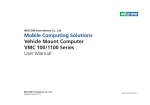
NEXCOM International Co., Ltd.
Mobile Computing Solutions
Vehicle Mount Computer
VMC 1000
User Manual
NEXCOM International Co., Ltd.
Published March 2014
www.nexcom.com
Contents
Contents
Preface
Lateral Side .............................................................................................9
I/O Connectors ........................................................................................0
GPS Connector ...................................................................................10
Multi-Connector..................................................................................11
DC Power Connector ..........................................................................12
DC Power Cable Connector ................................................................12
SIM CARD Connector .........................................................................13
USB Connector ...................................................................................13
Mic in Jack ..........................................................................................14
Line-out Jack .......................................................................................14
Copyright .............................................................................................. iv
Disclaimer .............................................................................................. iv
Acknowledgements ............................................................................... iv
Regulatory Compliance Statements ........................................................ iv
Declaration of Conformity....................................................................... iv
RoHS Compliance.................................................................................... v
Warranty and RMA................................................................................. vi
Safety Information .................................................................................vii
Installation Recommendations.................................................................vii
Safety Precautions..................................................................................viii
Technical Support and Assistance............................................................ ix
Conventions Used in this Manual............................................................ ix
Global Service Contact Information.......................................................... x
Package Contents...................................................................................xii
Ordering Information.............................................................................xiii
Chapter 2: Jumpers And Connectors
Before You Begin...................................................................................15
Precautions............................................................................................15
Jumper..................................................................................................16
Locations of the Jumpers and Connectors..............................................17
Panel Connector ...................................................................................18
Touch Screen Connector .......................................................................19
Button & Sensor & LED Connector ........................................................19
Speaker Connector ...............................................................................20
8051 Download Connector ...................................................................20
RTC Control Connector .........................................................................21
RTC Battery Connector .........................................................................21
Backlight Connector(power) ..................................................................22
Backlight Connector(data) .....................................................................22
Chapter 1: Product Introduction
Overview.................................................................................................1
Key Features............................................................................................1
Hardware Specifications...........................................................................3
Getting to Know VTC 1000.....................................................................7
Front Panel..............................................................................................7
Rear Panel................................................................................................8
Copyright © 2011 NEXCOM International Co., Ltd. All rights reserved
ii
VMC 1000 User Manual
Contents
CCD Conector ......................................................................................23
PORT 80 Connector ..............................................................................23
MINI PCIE Connector ............................................................................24
GAL Download Connector ....................................................................27
Input Voltage Control Switch ................................................................27
POWER_IN Connector ...........................................................................28
Chapter 3: System Setup
Installing a WLAN module or WWAN module.........................................29
Appendix A: I/O Address Function
I/O Address Function..............................................................................31
Appendix B: Vehicle Power Management Setup
Vehicle Power Management Setup.........................................................37
Appendix C: Power Consumption
Power Consumption..............................................................................44
Appendix D: SMS Wake-up setting
SMS Wake-up setting............................................................................45
Appendix E: RTC Wake-up setting
RTC Wake-up setting.............................................................................51
Copyright © 2011 NEXCOM International Co., Ltd. All rights reserved
iii
VMC 1000 User Manual
Preface
Preface
Copyright
Regulatory Compliance Statements
This publication, including all photographs, illustrations and software, is
protected under international copyright laws, with all rights reserved. No
part of this manual may be reproduced, copied, translated or transmitted
in any form or by any means without the prior written consent from
NEXCOM International Co., Ltd.
This section provides the FCC compliance statement for Class A devices and
describes how to keep the system CE compliant.
Declaration of Conformity
FCC
Disclaimer
This equipment has been tested and verified to comply with the limits for
a Class A digital device, pursuant to Part 15 of FCC Rules. These limits are
designed to provide reasonable protection against harmful interference when
the equipment is operated in a commercial environment. This equipment
generates, uses, and can radiate radio frequency energy and, if not installed
and used in accordance with the instructions, may cause harmful interference
to radio communications. Operation of this equipment in a residential area
(domestic environment) is likely to cause harmful interference, in which
case the user will be required to correct the interference (take adequate
measures) at their own expense.
The information in this document is subject to change without prior notice
and does not represent commitment from NEXCOM International Co., Ltd.
However, users may update their knowledge of any product in use by
constantly checking its manual posted on our website: http://www.nexcom.
com. NEXCOM shall not be liable for direct, indirect, special, incidental, or
consequential damages arising out of the use of any product, nor for any
infringements upon the rights of third parties, which may result from such
use. Any implied warranties of merchantability or fitness for any particular
purpose is also disclaimed.
CE
Acknowledgements
The product(s) described in this manual complies with all applicable European Union (CE) directives if it has a CE marking. For computer systems to
remain CE compliant, only CE-compliant parts may be used. Maintaining CE
compliance also requires proper cable and cabling techniques.
VMC 1000 is a trademark of NEXCOM International Co., Ltd. All other product
names mentioned herein are registered trademarks of their respective owners.
Copyright © 2011 NEXCOM International Co., Ltd. All rights reserved
iv
VMC 1000 User Manual
Preface
RoHS Compliance
How to recognize NEXCOM RoHS Products?
NEXCOM RoHS Environmental Policy and Status Update
For existing products where there are non-RoHS and RoHS versions, the suffix “(LF)” will be added to the compliant product name.
NEXCOM is a global citizen for building the digital
infrastructure. We are committed to providing green
products and services, which are compliant with European Union RoHS (Restriction on Use of Hazardous
Substance in Electronic Equipment) directive 2002/95/
EU, to be your trusted green partner and to protect
our environment.
All new product models launched after January 2006 will be RoHS compliant. They will use the usual NEXCOM naming convention.
RoHS restricts the use of Lead (Pb) < 0.1% or 1,000ppm, Mercury (Hg)
< 0.1% or 1,000ppm, Cadmium (Cd) < 0.01% or 100ppm, Hexavalent
Chromium (Cr6+) < 0.1% or 1,000ppm, Polybrominated biphenyls (PBB) <
0.1% or 1,000ppm, and Polybrominated diphenyl Ethers (PBDE) < 0.1% or
1,000ppm.
In order to meet the RoHS compliant directives, NEXCOM has established an
engineering and manufacturing task force in to implement the introduction
of green products. The task force will ensure that we follow the standard
NEXCOM development procedure and that all the new RoHS components
and new manufacturing processes maintain the highest industry quality levels for which NEXCOM are renowned.
The model selection criteria will be based on market demand. Vendors and
suppliers will ensure that all designed components will be RoHS compliant.
Copyright © 2011 NEXCOM International Co., Ltd. All rights reserved
v
VMC 1000 User Manual
Preface
Warranty and RMA
NEXCOM Warranty Period
making sure it is durable enough to be resistant against further damage and deterioration during transportation. In case of damages occurred
during transportation, the repair is treated as “Out of Warranty.”
NEXCOM manufactures products that are new or equivalent to new in accordance with industry standard. NEXCOM warrants that products will be
free from defect in material and workmanship for 2 years, beginning on the
date of invoice by NEXCOM. HCP series products (Blade Server) which are
manufactured by NEXCOM are covered by a three year warranty period.
?? Any products returned by NEXCOM to other locations besides the customers’ site will bear an extra charge and will be billed to the customer.
Repair Service Charges for Out-of-Warranty Products
NEXCOM Return Merchandise Authorization (RMA)
NEXCOM will charge for out-of-warranty products in two categories, one is
basic diagnostic fee and another is component (product) fee.
?? Customers shall enclose the “NEXCOM RMA Service Form” with the returned packages.
System Level
?? Component fee: NEXCOM will only charge for main components such as
SMD chip, BGA chip, etc. Passive components will be repaired for free,
ex: resistor, capacitor.
?? Customers must collect all the information about the problems encountered and note anything abnormal or, print out any on-screen messages,
and describe the problems on the “NEXCOM RMA Service Form” for the
RMA number apply process.
?? Items will be replaced with NEXCOM products if the original one cannot
be repaired. Ex: motherboard, power supply, etc.
?? Customers can send back the faulty products with or without accessories
(manuals, cable, etc.) and any components from the card, such as CPU
and RAM. If the components were suspected as part of the problems,
please note clearly which components are included. Otherwise, NEXCOM
is not responsible for the devices/parts.
?? Replace with 3rd party products if needed.
?? If RMA goods can not be repaired, NEXCOM will return it to the customer
without any charge.
?? Customers are responsible for the safe packaging of defective products,
Copyright © 2011 NEXCOM International Co., Ltd. All rights reserved
vi
VMC 1000 User Manual
Preface
Board Level
▪▪ When replacing parts, ensure that your service technician uses parts spec-
?? Component fee: NEXCOM will only charge for main components, such
as SMD chip, BGA chip, etc. Passive components will be repaired for free,
ex: resistors, capacitors.
▪▪ Avoid using the system near water, in direct sunlight, or near a heating
ified by the manufacturer.
device.
load of the system unit does not solely rely for support from the
rackmounts located on the sides. Firm support from the bottom is highly
necessary in order to provide balance stability.
▪▪ The
If RMA goods can not be repaired, NEXCOM will return it to the customer
without any charge.
The computer is provided with a battery-powered real-time clock circuit.
There is a danger of explosion if battery is incorrectly replaced. Replace only
with the same or equivalent type recommended by the manufacturer. Discard used batteries according to the manufacturer’s instructions.
Warnings
Read and adhere to all warnings, cautions, and notices in this guide and
the documentation supplied with the chassis, power supply, and accessory
modules. If the instructions for the chassis and power supply are inconsistent
with these instructions or the instructions for accessory modules, contact
the supplier to find out how you can ensure that your computer meets
safety and regulatory requirements.
Installation Recommendations
Ensure you have a stable, clean working environment. Dust and dirt can get
into components and cause a malfunction. Use containers to keep small
components separated.
Cautions
Electrostatic discharge (ESD) can damage system components. Do the described procedures only at an ESD workstation. If no such station is available, you can provide some ESD protection by wearing an antistatic wrist
strap and attaching it to a metal part of the computer chassis.
Adequate lighting and proper tools can prevent you from accidentally damaging the internal components. Most of the procedures that follow require
only a few simple tools, including the following:
Safety Information
Before installing and using the device, note the following precautions:
•
•
•
•
▪▪ Read all instructions carefully.
▪▪ Do not place the unit on an unstable surface, cart, or stand.
▪▪ Follow all warnings and cautions in this manual.
Using your fingers can disconnect most of the connections. It is recommended that you do not use needlenose pliers to disconnect connections as
these can damage the soft metal or plastic parts of the connectors.
Copyright © 2011 NEXCOM International Co., Ltd. All rights reserved
vii
A Philips screwdriver
A flat-tipped screwdriver
A grounding strap
An anti-static pad
VMC 1000 User Manual
Preface
Safety Precautions
12. If the equipment is not used for a long time, disconnect it from the
power source to avoid damage by transient overvoltage.
1.
2. Keep this User Manual for later reference.
13. Never pour any liquid into an opening. This may cause fire or electrical
shock.
3. Disconnect this equipment from any AC outlet before cleaning. Use a
damp cloth. Do not use liquid or spray detergents for cleaning.
14. Never open the equipment. For safety reasons, the equipment should
be opened only by qualified service personnel.
4. For plug-in equipment, the power outlet socket must be located near
the equipment and must be easily accessible.
15. If one of the following situations arises, get the equipment checked by
service personnel:
5. Keep this equipment away from humidity.
a. The power cord or plug is damaged.
6. Put this equipment on a stable surface during installation. Dropping it
or letting it fall may cause damage.
b. Liquid has penetrated into the equipment.
c. The equipment has been exposed to moisture.
7.
d. The equipment does not work well, or you cannot get it to work
according to the user’s manual.
e. The equipment has been dropped and damaged.
f. The equipment has obvious signs of breakage.
Read these safety instructions carefully.
Do not leave this equipment in either an unconditioned environment
o
or in a above 40 C storage temperature as this may damage the equipment.
8. The openings on the enclosure are for air convection to protect the
equipment from overheating. DO NOT COVER THE OPENINGS.
16. Do not place heavy objects on the equipment.
9. Make sure the voltage of the power source is correct before connecting the equipment to the power outlet.
17. The unit uses a three-wire ground cable which is equipped with a third
pin to ground the unit and prevent electric shock. Do not defeat the
purpose of this pin. If your outlet does not support this kind of plug,
contact your electrician to replace your obsolete outlet.
10. Place the power cord in a way so that people will not step on it. Do
not place anything on top of the power cord. Use a power cord that
has been approved for use with the product and that it matches the
voltage and current marked on the product’s electrical range label. The
voltage and current rating of the cord must be greater than the voltage and current rating marked on the product.
18. CAUTION: DANGER OF EXPLOSION IF BATTERY IS INCORRECTLY REPLACED. REPLACE ONLY WITH THE SAME OR EQUIVALENT TYPE RECOMMENDED BY THE MANUFACTURER. DISCARD USED BATTERIES
ACCORDING TO THE MANUFACTURER’S INSTRUCTIONS.
11. All cautions and warnings on the equipment should be noted.
Copyright © 2011 NEXCOM International Co., Ltd. All rights reserved
19. The computer is provided with CD drives that comply with the appropriate safety standards including IEC 60825.
viii
VMC 1000 User Manual
Preface
Technical Support and Assistance
Conventions Used in this Manual
1. For the most updated information of NEXCOM products, visit NEXCOM’s
website at www.nexcom.com.
Warning: Information about certain situations, which if not observed, can cause personal injury. This will prevent injury to yourself when performing a task.
2. For technical issues that require contacting our technical support team or
sales representative, please have the following information ready before
calling:
Caution: Information to avoid damaging components or losing
data.
– Product name and serial number
– Detailed information of the peripheral devices
– Detailed information of the installed software (operating system,
version, application software, etc.)
– A complete description of the problem
– The exact wordings of the error messages
Note: Provides additional information to complete a task easily.
Battery - Safety Measures
Warning!
Caution
1. Handling the unit: carry the unit with both hands and handle it with
care.
• Risk of explosion if battery is replaced by an incorrect type.
• Dispose of used batteries according to the instructions.
2. Maintenance: to keep the unit clean, use only approved cleaning products or clean with a dry cloth.
Safety Warning
This equipment is intended for installation in a Restricted Access
Location only.
3. CompactFlash: Turn off the unit’s power before inserting or removing a
CompactFlash storage card.
Resetting the Date and Time
Note: Remember to reset the date and time upon receiving the
product. You can set them in the AMI BIOS. Refer to chapter 4 for
more information.
Copyright © 2011 NEXCOM International Co., Ltd. All rights reserved
ix
VMC 1000 User Manual
Preface
Global Service Contact Information
Headquarters
Japan
NEXCOM Japan
15F, No. 920, Chung-Cheng Rd.,
ZhongHe District, New Taipei City, 23586,
Taiwan, R.O.C.
Tel: +886-2-8226-7786
Fax: +886-2-8226-7782
www.nexcom.com
9F, Tamachi Hara Bldg., 4-11-5, Shiba Minato-ku,
Tokyo, 108-0014, Japan
Tel: +81-3-5419-7830
Fax: +81-3-5419-7832
Email: [email protected]
www.nexcom-jp.com
America
China
NEXCOM China
NEXCOM International Co., Ltd.
USA
NEXCOM USA
2F, Block 4, Venus Plaza, Bldg. 21,
ZhongGuanCun Software Park, No. 8,
Dongbeiwang West Rd., Haidian District,
Beijing, 100193, China
Tel: +86-10-8282-6599
Fax: +86-10-8282-5955
Email: [email protected]
www.nexcom.cn
2883 Bayview Drive,
Fremont CA 94538, USA
Tel: +1-510-656-2248
Fax: +1-510-656-2158
Email: [email protected]
www.nexcom.com
Asia
Shanghai Office
Taiwan
Central Taiwan Office
Room 603/604, Huiyinmingzun Plaza Bldg., 1,
No.609, Yunlin East Rd.,
Shanghai, 200062, China
Tel: +86-21-5278-5868
Fax: +86-21-3251-6358
Email: [email protected]
www.nexcom.cn
16F, No.250, Sec. 2, Chongde Rd., Beitun Dist., Taichung City 406, R.O.C.
Tel: +886-4-2249-1179
Fax: +886-4-2249-1172
Email: [email protected]
www.nexcom.com.tw
Copyright © 2011 NEXCOM International Co., Ltd. All rights reserved
x
VMC 1000 User Manual
Preface
Europe
Shenzhen Office
Room1707, North Block, Pines Bldg.,
No.7 Tairan Rd., Futian Area,
Shenzhen, 518040, China
Tel: +86-755-8332-7203
Fax: +86-755-8332-7213
Email: [email protected]
www.nexcom.cn
Italy
NEXCOM ITALIA S.r.l
Via Gaudenzio Ferrari 29,
21047 Saronno (VA), Italia
Tel: +39 02 9628 0333
Fax: +39 02 9286 9215
Email: [email protected]
www.nexcomitalia.it
Wuhan Office
1-C1804/ 1805, Mingze Liwan,
No. 519 South Luoshi Rd.,
Hongshan District, Wuhan, 430070, China
Tel: +86-27-8722-7400
Fax: +86-27-8722-7400
Email: [email protected]
www.nexcom.cn
United Kingdom
NEXCOM EUROPE
10 Vincent Avenue,
Crownhill Business Centre,
Milton Keynes, Buckinghamshire MK8 0AB,
United Kingdom
Tel: +44-1908-267121
Fax: +44-1908-262042
Email: [email protected]
www.nexcom.eu
Chengdu Office
9F, Shuxiangxie, Xuefu Garden,
No.12 Section 1, South Yihuan Rd.,
Chengdu, 610061, China
Tel: +86-28-8523-0186
Fax: +86-28-8523-0186
Email: [email protected]
www.nexcom.cn
Copyright © 2011 NEXCOM International Co., Ltd. All rights reserved
xi
VMC 1000 User Manual
Preface
Package Contents
Before continuing, verify that the VMC 1000 package that you received is complete. Your VMC 1000 package should have all the items listed in the
following table.
Item
P/N
Name
Specification
Qty
1
5044440135X00
THERMAL PAD E-LIN
25x25x1mm K=5w/mk TP-1800G
4
2
5044440303X00
THERMAL PAD FOR VMC1000 E-LIN:TP1800G
25x25x2mm K=5w/mk
1
3
6023303701X00
(N)DB37 CABLE FOR VMC1000 SUNJET:SL812822805
D-SUB M37P SR L=300mm
1
4
60233PW236X00
(N)POWER DOCKING CABLE FOR VMC1000
SUNJET:SL812822822
UL2464 20AWG L=130mm
1
5
60233SAM05X00
GPS ANTENNA
5M /SMA180P
1
6
602DCD0405X00
CD DRIVER
Copyright © 2011 NEXCOM International Co., Ltd. All rights reserved
1
xii
VMC 1000 User Manual
Preface
Ordering Information
The following provides ordering information for VMC 1000.
• VMC 1000 (P/N: 10VC0100000X0)
- 7-inch All in One Vehicle Mount Computer with Touch Screen and Smart
Brightness Control and Intel® Atom™ E640 1.0Ghz processor with 1GB
DDR2, GPS module and GPS antenna
Copyright © 2011 NEXCOM International Co., Ltd. All rights reserved
xiii
VMC 1000 User Manual
Chapter 1: Product Introduction
Chapter 1: Product Introduction
Overview
VMC 1000 Front View
VMC 1000 Rear View
Key Features
• Variety wireless communication options
• Wide Range DC input from 6~36V
• Compliant with IP54
• Certified by CE/ FCC/ e13 Mark
• 7” WVGA TFT LCD with LED backlight
• Compact and fanless design
• Built-in Intel® Atom™ E640 1.0GHz processor
• Wake on RTC /SMS
• GPS receiver on board
Copyright © 2011 NEXCOM International Co., Ltd. All rights reserved
1
VMC 1000 User Manual
Chapter 1: Product Introduction
VMC 1000, a 7-inch all in one vehicle computer, is designed for the transportation
application. Adopting the latest low power consumption processor, Intel®
Atom™ E640, it integrates the high resolution LCD with the brightness of 400
nits and 4-wire resistive touch sensor.
VMC 1000 does not compromise with its space to scarify its functional
features. It provides RS-232/422/485, USB 2.0, GPIO and LAN signal via
DB37 connector to secure the cable simultaneously in the vehicle vibration.
Its mounting hole is compatible with VESA75 and can be installed in the
vehicle with limited space via RAM mount kits.
Copyright © 2011 NEXCOM International Co., Ltd. All rights reserved
2
VMC 1000 User Manual
Chapter 1: Product Introduction
Hardware Specifications
Main Chipset
I/O Interfaces - Lateral Side
• Intel EG20T
• 1 x Line-in
• 1 x Line-out
• 1 x USB
• 1 x SIM slot
• 1 x Power Button
• 1 x Reset Button
®
CPU
• Intel® Atom™ E640 1.0GHz
Memory
• On board 1GB DDR2 800MHz
Bottom Side
Expansion
• Mini PCIe socket (USB) x 1 (for 3.5G module)
• 1 x GPS module
• Mini PCIe socket (PCIe + USB + SATA) x 1 (for WLAN module)
• 1 x DB9 male connector (RS-232)
• 1 x DB37 female connector (1x LAN ; 2x USB ; 1x RS232 ; 1 x RS422/485 ;
6 x GPIO ; 1 x CAN)
• 6~36V Wide Range DC power input
• 1 x SMA connector for GPS antenna
I/O Interfaces - Front
Expandable Storage
• On Screen Display Buttons x 5 Power On/ Off Volume Control (+/-)
Brightness Control (+/-)
• Light Sensor
• 2 x LED indicators
• 2 x Built-in Speakers (1W)
• 1 x mSATA
Copyright © 2011 NEXCOM International Co., Ltd. All rights reserved
Power Management
• Selectable boot-up & shut-down voltage for low power protection
• HW design ready for 8-level delay time on/off at user’s self configuration
• Power on/off ignition, software detectable
• Supports S3/S4 suspend mode ; wake on RTC/ SMS
3
VMC 1000 User Manual
Chapter 1: Product Introduction
Hardware Specifications
Construction
• Shock (with SSD)
- Operating: MIL-STD-810F, Method 516.5, Procedure I, Trucks and
semi-trailers=20g
- Crash Hazard: MIL-STD-810F, Method 516.5, Procedure V, Ground
equipment=75g
• Plastic case with aluminum die casting heatsink
• Compliant with IP54
Certifications
Dimensions
• 185.4 mm (W) x 141.4 mm (D) x 50.42 mm (H) (7.3” x 5.57” x 1.99”)
• 1 Kg (2.20 Lb)
Environment
• CE approval
• FCC Class B
• e13 Mark
• Operating temperatures:
Ambient with air:
-20°C to 50°C
• Storage temperatures: -30°C to 80°C
Power Management
• Relative humidity: 10% to 90% (Non-condensing)
• Vibration (random): 2g@5~500 Hz
• Vibration
Operating: MIL-STD-810F, Method 514.5, Category 20, Ground
Vehicle – Highway Truck
Storage: MIL-STD-810F, Method 514.5, Category 24, Integrity Test
Copyright © 2011 NEXCOM International Co., Ltd. All rights reserved
• Power-on delay time is selectable by BIOS to disable and enable in 10sec
/ 30sec / 1min / 5min / 10 min / 15min / 30min / 1hr.
• Power-off delay time is selectable by BIOS to disable and enable in 20sec
/ 1min / 5min / 10min / 30min / 1hr / 6hr / 18hr.
• S4 suspend mode
• Ignition On/Off status detectable by SW
• Low battery status detectable by SW
• Ignition enable/disable is jumper selectable
4
VMC 1000 User Manual
Chapter 1: Product Introduction
• Shut down system automatically when the system’s internal temperature
is over 80C.
• VMC 1000 will automatically shut down 5 minutes after the duration
of low battery voltage is over 60 sec. User can detect this situation via
software.
• If the ignition is off and the system is still on after 3 minutes, VMC 1000
will shut down automatically.
• If the ignition is off, the user can detect this status via the software.
• If the ignition is turned on again and the power-off delay is in progress,
VMC 1000 will cancel the delay function and will continue to operate
normally.
• If the ignition is turned on again and the power-off delay ended, VMC 1000
will shut down completely will power-on again automatically.
• If the ignition is turned off again and power-on delay is in progress, VMC
1000 will cancel the delay and stay in power-off status.
• If the ignition is turned off again and the power-on delay ended (in BIOS
process), VMC 1000 will shut down immediately.
• If VMC 1000 is off, only below 10mA is used.
Copyright © 2011 NEXCOM International Co., Ltd. All rights reserved
5
VMC 1000 User Manual
Chapter 1: Product Introduction
Copyright © 2011 NEXCOM International Co., Ltd. All rights reserved
6
VMC 1000 User Manual
Chapter 1: Product Introduction
Getting to Know VMC 1000
Front View
6
7
5
3
2
1
4
1.Power On/Off Control
3.Volume Control
Press this button for 4 seconds -- the monitor will turn on.
Audio volume can be adjusted in 8 levels using the buttons.
2.Brightness Control
4.LED
There are two modes for Brightness Control: Manual Mode
PWR LED is turned on when VMD 1000 is powered on.
LCD brightness can be adjusted in 4 levels using the “+” or “-” buttons.
Mode LED is turned on when brightness control is in Auto Mode
Auto Mode
5.Light Sensor
The built-in light sensor will detect environmental brightness and adjust
LCD brightness automatically.
6.HSDPA Module Antenna Mounting Hole
7.WIFI Module Antenna Mounting Hole
Switching between Manual Mode and Auto Mode
To toggle between Manual Mode and Auto Mode, press and hold the “+”
or “-” buttons for 4 seconds.
Copyright © 2011 NEXCOM International Co., Ltd. All rights reserved
7
VMC 1000 User Manual
Chapter 1: Product Introduction
Rear View
4
3
2
1
1.GPS antenna mounting.
2.RS-232 Connector (DB9)
3.DB37 female connector (1x LAN ; 2x USB ; 1x RS232 ; 1 x
RS422/485 ;6 x GPIO ; 1x CAN)
4.6~36V Wide Range DC power input
Copyright © 2011 NEXCOM International Co., Ltd. All rights reserved
8
VMC 1000 User Manual
Chapter 1: Product Introduction
Getting to Know VMC 1000
Lateral Side
8
7
6
5
1.SIM slot
2.USB 2.0/1.1
3.Mic-in
4.Line-out
Another side is power button and reset button3.Volume Control
Copyright © 2011 NEXCOM International Co., Ltd. All rights reserved
9
VMC 1000 User Manual
Chapter 1: Product Introduction
Getting to Know VMC 1000
GPS Connector
RS232 Connector
Connector location: CN6
Connector size: GPS SMA Connector 5 Pin
Connector location: CN10
Connector size: Male DSUB-9 PIN
PIn
Definition
1
SP_DCD_0
2
SP_RXD_0
Pin
Definition
3
SP_TXD_0
1
RF_IN_F
4
SP_DTR_0
MH1
GND
5
CON0_GND
MH2
GND
6
SP_DSR_0
MH3
GND
7
SP_RTS_0
GND
8
SP_CTS_0
9
SP_RI_0
MH4
Copyright © 2011 NEXCOM International Co., Ltd. All rights reserved
10
VMC 1000 User Manual
Chapter 1: Product Introduction
DB37 PIN Connector
Connector location: CN9
Connector size: Female DB37 PIN Connector
Copyright © 2011 NEXCOM International Co., Ltd. All rights reserved
11
Pin
Definition
Pin
Definition
1
LAN_M0P
20
LAN_M0N
2
LAN_M1P
21
LAN_M1N
3
LAN_M2P
22
LAN_M2N
4
LAN_M3P
23
LAN_M3N
5
L_GND
24
G_OUT1
6
G_IN1
25
G_OUT2
7
G_IN2
26
G_OUT3
8
G_IN3
27
USB_VCC5
9
USB_VCC5
28
HUSB_6N_R
10
HUSB_6P_R
29
HUSB_7N_R
11
HUSB_7P_R
30
RS422_TX+
12
U_GND
31
RS422_TX-
13
RS422_RX+ / RS485_+
32
CANH
14
RS422_RX- / RS485_-
33
CANL
15
SP_RI_1
34
C_GND
16
SP_DCD_1
35
SP_RXD_1
17
SP_TXD_1
36
SP_RTS_1
18
SP_CTS_1
37
SP_DSR_1
19
SP_DTR_1
VMC 1000 User Manual
Chapter 1: Product Introduction
DC Power connector
Pin
Definition
1
V_IN 6~36V
2
IGNITION
3
GND
Copyright © 2011 NEXCOM International Co., Ltd. All rights reserved
DC Power cable connector
12
Pin color
Definition
YEL, HT
Solder together for V_IN
BLK
GND
VMC 1000 User Manual
Chapter 1: Product Introduction
SIM Card Reader Connector
USB Connector
Connector location: CN5
Connector location: USB1
Connector size: Single USB 4Pin
Pin
Definition
C1
UIM_PWR2
C2
UIM_RST2
C3
UIM_CLK2
C5
GND
C6
NC
C7
UIM_DAT2
Copyright © 2011 NEXCOM International Co., Ltd. All rights reserved
13
Pin
Definition
1
VCC
2
DATA-( USB_0N)
3
DATA+( USB_0P)
4
GND
VMC 1000 User Manual
Chapter 1: Product Introduction
Mic-in Jack
Line-out Jack
Connector location: CN7
Connector size: EAR PHONE JACK PINK
Connector location: CN8
Connector size: EAR PHONE JACK GREEN
Pin
Definition
Pin
Definition
1
FRONT_OUT_RC
1
NC
2
LINE_OUTD
2
MIC_JD
3
NC
3
NC
4
FRONT_OUT_LC
4
MIC_OUT-L
5
ACON_GND
5
ACON_GND
6
ACON_GND
6
ACON_GND
Copyright © 2011 NEXCOM International Co., Ltd. All rights reserved
14
VMC 1000 User Manual
Chapter 2: Jumpers and Connectors
Chapter 2: Jumpers and Connectors
ponents. Humid environment tend to have less static electricity than dry
environments. A grounding strap is warranted whenever danger of static
electricity exists.
This chapter describes how to set the jumpers on the motherboard. Note
that the following procedures are generic for all VTC 1000 series.
Before You Begin
Precautions
• Ensure you have a stable, clean working environment. Dust and dirt can
Computer components and electronic circuit boards can be damaged by
discharges of static electricity. Working on the computers that are still connected to a power supply can be extremely dangerous.
get into components and cause a malfunction. Use containers to keep
small components separated.
• Adequate lighting and proper tools can prevent you from accidentally
Follow the guidelines below to avoid damage to your computer or yourself:
damaging the internal components. Most of the procedures that follow
require only a few simple tools, including the following:
• Always disconnect the unit from the power outlet whenever you are
working inside the case.
• A Philips screwdriver
• A flat-tipped screwdriver
• If possible, wear a grounded wrist strap when you are working inside the
• A set of jewelers Screwdrivers
computer case. Alternatively, discharge any static electricity by touching
the bare metal chassis of the unit case, or the bare metal body of any
other grounded appliance.
• A grounding strap
• An anti-static pad
• Using your fingers can disconnect most of the connections. It is recom-
• Hold electronic circuit boards by the edges only. Do not touch the com-
mended that you do not use needle-nosed pliers to disconnect connections as these can damage the soft metal or plastic parts of the connectors.
ponents on the board unless it is necessary to do so. Don’t flex or stress
the circuit board.
• Leave all components inside the static-proof packaging that they shipped
• Before working on internal components, make sure that the power is off.
with until they are ready for installation.
Ground yourself before touching any internal components, by touching
a metal object. Static electricity can damage many of the electronic com-
Copyright © 2011 NEXCOM International Co., Ltd. All rights reserved
• Use correct screws and do not over tighten screws.
15
VMC 1000 User Manual
Chapter 2: Jumpers and Connectors
Jumper
A jumper is the simplest kind of electric switch. It consists of two metal
pins and a cap. When setting the jumpers, ensure that the jumper caps are
placed on the correct pins. When the jumper cap is placed on both pins, the
jumper is short. If you remove the jumper cap, or place the jumper cap on
just one pin, the jumper is open.
Refer to the illustrations below for examples of what the 2-pin and 3-pin
jumpers look like when they are short (on) and open (off).
Two-Pin Jumpers: Open (Left) and Short (Right)
Three-Pin Jumpers: Pins 1 and 2 Are Short
1
2
3
1
2
3
Copyright © 2011 NEXCOM International Co., Ltd. All rights reserved
16
VMC 1000 User Manual
Chapter 2: Jumpers and Connectors
Locations of the Jumpers and Connectors
The figure below is the main board which is the board used in the VMC 1000 system. It shows the locations of the jumpers and connectors.
J12
J6
SW1
SW2
J7
CN2
CN9
J8
J9
J10
CN3
CN5
J5
CN4
CN10
J3
J2
17
CN1
CN7
CN8
USB1
CN6
Copyright © 2011 NEXCOM International Co., Ltd. All rights reserved
VMC 1000 User Manual
Chapter 2: Jumpers and Connectors
Internal Connectors and Jumper Settings
Panel Connector
Connector size: 1.25mm WAFER 20P
Connector location: J7
J7
1
2
3
4
5
6
7
8
9
10
11
12
13
14
15
16
17
18
19
20
RX3+
RX3NC
FRC
GND3
RXC+
RXCGND2
RX2+
RX2MH2
GND1
RX1+
MH1
RX1GND0
RX0+
RX0LR
UD
VCC_IN1
VCC_IN2
PIN
Definition
PIN
Definition
1
RX3+
11
GND1
2
RX3-
12
RX1+
3
NC
13
RX1-
4
FRC
14
GND0
5
GND3
15
RX0+
6
RXC+
16
RX0-
7
RXC-
17
LR(default:1)
8
GND2
18
UD(default:0)
9
RX2+
19
VCC_IN1
10
RX2-
20
VCC_IN2
LCD_CON_20P
Copyright © 2011 NEXCOM International Co., Ltd. All rights reserved
18
VMC 1000 User Manual
Chapter 2: Jumpers and Connectors
Touch Screen Connector
Button & Sensor & LED Connector
Connector size: FPC_1X4P-1mm
Connector location: CN1
Connector size: 1mm Wafer 10 Pin180
Connector location: J5
MH1
MH2
O
CN1
1
2
3
4
MH1
MH2
MH1
MH2
FPC CON 1mm
1
2
3
4
1
2
3
4
5
6
7
8
9
10
WAFER-M-180-1mm
FPC_1X4P-1mm
PIN
Definition
1
TOUCH_XL
2
TOUCH_YD
3
TOUCH_XR
4
TOUCH_YU
Copyright © 2011 NEXCOM International Co., Ltd. All rights reserved
19
J5
PIN
Definition
1
LS_D
2
LS_A
3
KEY_V+
4
KEY_V-
5
KEY_BL+
6
KEY_BL-
7
BOT_M_N
8
AUTO_BL_LED
9
POWER_LED
10
GND
VMC 1000 User Manual
Chapter 2: Jumpers and Connectors
Speaker Connector
8051 Download Connector
O
O
Connector size: 1mm Wafer 2Pin 180
Connector location: J2, J6
J2
Connector size: 2.54mm PIN HEADER 5Pin 180
Connector location: JP3, JP5
WAFER-M-90-1mm
1
2
3
4
5
MH1
MH2
2
1
JP3
PIN-M-180-2.54mm
J2
JP3
JP5
PIN
Definition
PIN
Definition
PIN
Definition
1
FRONT_A_R+_R
1
+V3.3ALW
1
+V_MCU2
2
FRONT_A_R-_R
2
C2D_1
2
C2D_2
3
MRST_1
3
MRST_2
4
C2CK_1
4
C2CK_2
5
GND
5
GND
J6
PIN
Definition
1
FRONT_A_L+_R
2
FRONT_A_L-_R
Copyright © 2011 NEXCOM International Co., Ltd. All rights reserved
20
VMC 1000 User Manual
Chapter 2: Jumpers and Connectors
RTC Control Connector
RTC Battery Connector
Connector size: WAFER-M-180-1.25mm
Connector location: J4
J4
JP1
1
2
3
G2
2
1
G1
PIN-M-180-2.54mm
MH2
2
1
MH1
WAFER-M-180-1.25mm
JP1
J4
PIN
Definition
PIN
1
RTCRSTN
1
GND
2
RTC_CLR
2
VBAT1
3
RTCGND#
MH1
GND
MH2
GND
Copyright © 2011 NEXCOM International Co., Ltd. All rights reserved
21
Definition
VMC 1000 User Manual
Chapter 2: Jumpers and Connectors
Backlight Connector(power)
Backlight Connector(data)
O
O
Connector size: 1.25mm Wafer 2 Pin 90
Connector location: J10
Connector size: 1mm Wafer 2Pin 90
Connector location: J8
J8
J10
2
1
WAFER-M-90-1mm
J10
MH1
MH2
WAFER-M-90-1.25mm
MH1
MH2
2
1
J8
PIN
Definition
PIN
Definition
1
GND
1
Brightness
2
Panel_backlight
2
BK_EN
Copyright © 2011 NEXCOM International Co., Ltd. All rights reserved
22
VMC 1000 User Manual
Chapter 2: Jumpers and Connectors
CCD Conector
PORT 80 Connector
O
O
Connector size: 1mm Wafer 10 Pin 90
Connector location: J9
MH1
MH2
MH1
MH2
Connector size: 1mm Wafer 6 Pin 90
Connector location: J3
1
2
3
4
5
6
7
8
9
10
1
2
3
4
5
6
J3
WAFER-M-90-1mm
WAFER-M-90-1mm
J9
J9
J3
PIN
Definition
1
VCC3_S
PIN
Definition
2
VCC3_S
1
CCD_PWR
3
LPC_AD0
2
HUSB_9N
4
LPC_AD1
3
HUSB_9P
5
LPC_AD2
4
GND
6
LPC_AD3
5
CCD_EN_L
7
LPC_FRAME#
6
NC
8
LPC_CLK2
9
SIO_RST#
10
GND
Copyright © 2011 NEXCOM International Co., Ltd. All rights reserved
23
VMC 1000 User Manual
Chapter 2: Jumpers and Connectors
MINI PCIE Connector
MINI PCIE Connector Interface: M-Sata
Connector location: CN2
CN2
GND5
REFCLK+
REFCLKGND6
CLKREQ#
COEX2
COEX1
WAKE#
UIM_VPP
UIM_RESET
UIM_CLK
UIM_DATA
UIM_PWR
1.5V_3
GND12
3.3VSB_3
52
50
48
46
44
42
40
38
36
34
32
30
28
26
24
22
20
18
16
14
12
10
8
6
4
2
MH1
MH2
MH3
MH4
MH5
MH6
15
13
11
9
7
5
3
1
MINI PCIE CON 3.3VSB_2
REV1
GND7
REV2
Ver:1.2
1.5V_1
REV3
LED_WPAN#
REV4
GND14
LED_WLAN#
LED_WWAN#
3.3VSB_5
GND8
3.3VSB_4
USB_D+
GND13
USB_DGND0
PETp0
GND9
PETn0
SMBDAT
SMBCLK
GND2
1.5V_2
GND3
GND10
PERp0
PERn0
3.3VSB_1
GND4
PERST#
REV9/UIM_C4
W_DISABLE#
REV10/UIM_C8
GND11
MH1
MH2
MH3
MH4
MH5
MH6
51
49
47
45
43
41
39
37
35
33
31
29
27
25
23
21
19
17
PIN
Definition
PIN
Definition
8
NC
34
GND
9
GND
35
GND
10
NC
36
NC
11
NC
37
GND
12
NC
38
NC
13
NC
39
+3.3C_MINI
14
NC
40
GND
15
GND
41
+3.3C_MINI
16
NC
42
NC
17
NC
43
NC
18
GND
44
NC
PIN
Definition
PIN
Definition
19
NC
45
NC
1
NC
27
GND
20
NC
46
NC
2
+3.3C_MINI
28
D15VS
21
GND
47
NC
3
NC
29
GND
22
NC
48
D15VS
4
GND
30
NC
23
SATA_TXP1
49
NC
5
NC
31
SATA_RXN1
24
+3.3C_MINI
50
GND
6
D15VS
32
NC
25
SATA_TXN1
51
GND
7
NC
33
SATA_RXP1
26
GND
52
+3.3C_MINI
Copyright © 2011 NEXCOM International Co., Ltd. All rights reserved
24
VMC 1000 User Manual
Chapter 2: Jumpers and Connectors
MINI PCIE Connector Interface: Starnd Mini-PCI-e/ M-Sata
Connector location: CN3
PIN
Definition
PIN
Definition
PIN
Definition
PIN
Definition
1
PCIE_WAKE#
27
GND
20
MINICARD1_DIS#
46
NC
2
+3.3B_MINI
28
D15VS
21
GND
47
NC
3
NC
29
GND
22
WLAN_RESET#
48
D15VS
4
GND
30
SMB_CLK
23
mPCIE_RX_N
49
NC
5
NC
31
mPCIE_TX_N
24
+3.3B_MINI
50
GND
6
D15VS
32
SMB_DATA
25
mPCIE_RX_P
51
PRE-DEC
7
CLKREQ#
33
mPCIE_TX_P
26
GND
52
+3.3B_MINI
8
NC
34
GND
9
GND
35
GND
10
NC
36
USB_IN
11
MC_PCIE_CLK_N
37
GND
12
NC
38
USB_IP
13
MC_PCIE_CLK_P
39
+3.3B_MINI
14
NC
40
GND
15
GND
41
+3.3B_MINI
16
NC
42
NC
17
NC
43
GND
18
GND
44
LED_WLAN#
19
NC
45
NC
Copyright © 2011 NEXCOM International Co., Ltd. All rights reserved
25
VMC 1000 User Manual
Chapter 2: Jumpers and Connectors
MINI PCIE Connector Interface: USB ONLY
Connector location: CN4
PIN
Definition
PIN
Definition
PIN
Definition
PIN
Definition
1
NC
27
GND
20
3.5G_DIS#
46
NC
2
+3.3A_MINI
28
NC
21
GND
47
NC
3
NC
29
GND
22
NC
48
NC
4
GND
30
NC
23
NC
49
MINI_RXD_PCMDOUT_NC
5
NC
31
NC
24
NC
50
GND
6
NC
32
SMS_RI_3.5G
25
NC
51
MINI_TXD_PCMSY_NC
7
UMTS_GND
33
UMTS_RESET#
26
GND
52
+3.3A_MINI
8
UIM_PWR2
34
GND
9
GND
35
GND
10
UIM_DAT2
36
USB_3N
11
VCC_MSM26_DIG
37
GND
12
UIM_CLK2
38
USB_3P
13
NC
39
+3.3A_MINI
14
UIM_RST2
40
GND
15
GND
41
+3.3A_MINI
16
NC
42
3.5G_LED#
17
NC
43
GND
18
GND
44
NC
19
NC
45
NC
Copyright © 2011 NEXCOM International Co., Ltd. All rights reserved
26
VMC 1000 User Manual
Chapter 2: Jumpers and Connectors
GAL Download Connector
Input Voltage Control Switch
O
O
Connector size: 2.54mm PIN HEADER 6Pin 180
Connector location: JP2
JP2
SW3
1
2
4
3
ON
1
2
3
4
5
6
Connector size: 2x2 DIP SWITCH 180
Connector location: SW3
PIN-M-180-2.54mm
PIN
Definition
PIN
Definition
1
V3P3_G
1
POWERSW
2
GND
2
12V24V
3
TCK
3
GND
4
TDO
4
GND
5
TDI
6
TMS
Copyright © 2011 NEXCOM International Co., Ltd. All rights reserved
27
VMC 1000 User Manual
Chapter 2: Jumpers and Connectors
POWER_IN Connector
O
MH1
MH2
Connector size: 2.5mm Wafer 6 Pin 180
Connector location: J12
1
2
3
4
5
6
7
8
9
10
11
12
13
14
15
16
J12
WAFER-M-180-1.0mm
PIN
Definition
PIN
Definition
1
V_IN
9
IGNITION
2
V_IN
10
V_GND
3
V_IN
11
V_GND
4
V_IN
12
V_GND
5
V_IN
13
V_GND
6
V_IN
14
V_GND
7
V_IN
15
V_GND
8
IGNITION
16
V_GND
Copyright © 2011 NEXCOM International Co., Ltd. All rights reserved
28
VMC 1000 User Manual
Chapter 3: System Setup
Chapter 3: System Setup
Installing a WLAN module or WWAN module
CAUTION!
Prior to removing the chassis cover, make sure the unit’s power is off and disconnected from the power sources to prevent electric shock or system damage.
1. Remove these screws and put them in a safe place for later use.
2.
Remove the rear cover of the VMC1000.
The Mini PCI Express slot shown below is used to install a WLAN
module or 3.5G commu-nication module such as GPRS,
UMTS or HSDPA module.
For 3.5G module
For WLAN module
mSATA
Copyright © 2011 NEXCOM International Co., Ltd. All rights reserved
29
VMC 1000 User Manual
Chapter 3: System Setup
System Setup
3. Insert the module into the Mini PCI Express slot at a 45 degrees angle
until the gold-plated connector on the edge of the module completely
disappears inside the slot. And then attach RF cable to the module.
4. Before you install the rear cover, please check the all thermal pads are on
the heatsink.
Copyright © 2011 NEXCOM International Co., Ltd. All rights reserved
30
VMC 1000 User Manual
Appendix A: I/O Address Function
Appendix A: I/O Address Function
(*) for default setting
GPIO LED / UMTS LED / Ignition Status
I/O port : 0EE0H
Bit
Function Description
Bit 0
GPIO LED (VMC1000 UNUSED)
0: OFF (*)
1: ON
Bit 1
UMTS LED (VMC1000 UNUSED)
0: LED for Wireless (*)
1: LED for 3.5G and Wireless
Bit 2
Ignition (read only)
0: OFF
1: ON
Bit 3
Status of Car Battery
0: Car Battery is OK
1: Car Battery is Low voltage
Copyright © 2011 NEXCOM International Co., Ltd. All rights reserved
31
VMC 1000 User Manual
Appendix A: I/O Address Function
WDT
I/O port : 0EE5H
Onboard Module Disable/Enable(1)
I/O port : 0EE6H
Bit
Function Description
Bit
Bit 3
WDT Disable/Enable
0: Disable (*)
1: Enable
Bit 0
3.5G module
0: Disable
1: Enable (*)
Bit 1
WLAN module
0: Disable
1: Enable (*)
Bit 2, 1, 0: Time Setting
Function Description
Bit 2
RESERVED
Bit 2~0
Time (sec)
Bit 3
RESERVED
000
1 (*)
Bit 4
001
2
010
4
Wake on 3.5G module
0: Disable
1: Enable (*)
011
8
Bit 5
100
16
101
32
Wake on RTC module
0: Disable
1: Enable (*)
110
64
111
128
Auto clear WDT timer when reading/writing I/O port 0EE5H.
Copyright © 2011 NEXCOM International Co., Ltd. All rights reserved
32
VMC 1000 User Manual
Appendix A: I/O Address Function
Delay On Time Setting
I/O port : 0EE7H
Bit7: Power On Delay
0: DISABLE(*)
1: ENABLE
Bit6: Power Off Delay
0: DISABLE(*)
1: ENABLE
Startup and Shutdown Voltage Control
I/O port : 0EE8H
Only set by switch on motherboard(read only)
Bit5~6
Function Description
000
10 sec
001
30 sec
010
1 min
011
5 min
100
10 min
101
15 min
110
30 min
111
1 hour
Time (sec)
000
20 sec
001
1 min
010
5 min
011
10 min
100
30 min
101
1 hour
110
6 hour
111
18 hour
Copyright © 2011 NEXCOM International Co., Ltd. All rights reserved
Input Voltage
11
12V
01
24V
10
6~36V
00
6~36V
When input voltage 12V
Bit1~0
00
01
Input Voltage 12V
Startup
Shutdown
11.5V
10.5V
Startup
Shutdown
12V
Delay Off Time Setting
Bit 2~0
Bit3~2
10
11
33
11V
Startup
Shutdown
12.5V
11V
Startup
Shutdown
12.5V
11.5V
VMC 1000 User Manual
Appendix A: I/O Address Function
Setup Command
I/O port : 0EE9H
When input voltage 24V
Bit1~0
00
01
10
11
Restart the Setup Command
Enable byte
Input Voltage 24V
Startup
Shutdown
23V
21V
Startup
Shutdown
24V
22V
Startup
Shutdown
25V
22V
Startup
Shutdown
25V
23V
Copyright © 2011 NEXCOM International Co., Ltd. All rights reserved
AA
Using end byte to tell the data flow end
34
Data
End byte
(Delay time)(Startup/Shutdown voltage setting)
55
VMC 1000 User Manual
Appendix A: I/O Address Function
Onboard Module Disable/Enable(1)
I/O port : 0EEAH
Bit
Startup Time Setting
I/O port: 0EECH(clock Timer)
Bit0~7: the hour value(binary)
Function Description
Bit 0
Status of RS422/485 MODULE1
0: RS-422
1: RS-485 (*)
I/O port: 0EEDH(clock Timer)
Bit0~7: the minute value(binary)
I/O port: 0EEEH( User setting Time)
Bit0~7: the hour value(binary)
I/O port: 0EEFH( User setting Time)
Bit0~7: the minute value(binary)
GAL Download control
I/O port : 0EEBH
Restart the Setup Command
Enable byte
AA
Copyright © 2011 NEXCOM International Co., Ltd. All rights reserved
35
VMC 1000 User Manual
Appendix A: I/O Address Function
GPIO
I/O port : 0EE4H, Default Value : 0x38H
Bit
Function Description
Bit 0-2
GPO 0-2
Bit 3-5
GPI 0-2
Copyright © 2011 NEXCOM International Co., Ltd. All rights reserved
36
VMC 1000 User Manual
Appendix B: Vehicle Power Management Setup
Appendix B: Vehicle Power Management Setup
External Power Output Setting
External +12V and +5V Turn On Simultaneously
Copyright © 2011 NEXCOM International Co., Ltd. All rights reserved
External +12V and +5V Turn Off Simultaneously
37
VMC 1000 User Manual
Appendix B: Vehicle Power Management Setup
Vehicle Power Management Setup
External Power Output Setting
External +12V Turn On Only
Copyright © 2011 NEXCOM International Co., Ltd. All rights reserved
External +5V Turn On Only
38
VMC 1000 User Manual
Appendix B: Vehicle Power Management Setup
Vehicle Power Management Setup
Startup and Shutdown Voltage Setting
1.
If the input voltage setting is 12V :
set the startup voltage to 11.5V and the shutdown voltage to 10.5V.
If the input voltage setting is 12V :
set the startup voltage to 12V and the shutdown voltage to 11V.
If the input voltage setting is 12V :
set the startup voltage to 12.5V and the shutdown voltage to 11.5V.
If the input voltage setting is 12V :
set the startup voltage to 12.5V and the shutdown voltage to 11V.
Copyright © 2011 NEXCOM International Co., Ltd. All rights reserved
39
VMC 1000 User Manual
Appendix B: Vehicle Power Management Setup
Vehicle Power Management Setup
Startup and Shutdown Voltage Setting
2.
If the input voltage setting is 24V :
set the startup voltage to 23V and the shutdown voltage to 21V.
If the input voltage setting is 24V :
set the startup voltage to 24V and the shutdown voltage to 22V.
If the input voltage setting is 24V :
set the startup voltage to 25V and the shutdown voltage to 22V.
If the input voltage setting is 24V :
set the startup voltage to 25V and the shutdown voltage to 23V.
Copyright © 2011 NEXCOM International Co., Ltd. All rights reserved
40
VMC 1000 User Manual
Appendix B: Vehicle Power Management Setup
Vehicle Power Management Setup
Startup and Shutdown Voltage Setting
4.
If the input voltage setting is 6v~36V ignore the startup/shutdown setting.
Copyright © 2011 NEXCOM International Co., Ltd. All rights reserved
41
VMC 1000 User Manual
Appendix B: Vehicle Power Management Setup
Vehicle Power Management Setup
Power-on Delay Setting
Disable Power-on Delay
Enable Power-on Delay
Delay time can be set at 10sec/30sec/1min./5min./10min./15min./30min./
1hour.
Copyright © 2011 NEXCOM International Co., Ltd. All rights reserved
42
VMC 1000 User Manual
Appendix B: Vehicle Power Management Setup
Vehicle Power Management Setup
Power-on Delay Setting
Disable Power-off Delay
Enable Power-off Delay
Delay time can be set at 20sec/1min./5min./10min./30min./1hour/6hour/
18hour.
Copyright © 2011 NEXCOM International Co., Ltd. All rights reserved
43
VMC 1000 User Manual
Appendix C: Power Consumption
Appendix C: Power Consumption
Test Equipment/Tool
DUT#1: VMC1000 with 32GB mSATA
DUT#2: VMC1000 with 32GB mSATA and 3.5G WWAN module
Windows XP
Burn-in Software: Version 5.0
Test Condition
Room temperature
Power supply graduation: 12V 5A
Test Procedure:
1. Start of all function at DUT and measure power consumption.
2. Get system into suspend mode and measure power consumption.
Unit
Idle Mode
100% Burn-in Mode
S3
S4
S5
DUT#1
1.3A
1.33A
148mA
12mA
12mA
DUT#2
1.33A
1.35A
72mA
56.7mA
56.7mA
* Device: N/A
Copyright © 2011 NEXCOM International Co., Ltd. All rights reserved
44
VMC 1000 User Manual
Appendix D: SMS Wake-up setting
Appendix D: SMS Wake-up setting
Utilizing sleep mode on the Serra MC8970V 3.5G module and allowing for remote wake up via SMS. (The specification of MC8970V and AT command
reference are in the CD-ROM)
Two process to setting the SMS wake-up mode for VTC1000. Please do the following to set it up.
A. BIOS setting
(1) Press <Enter> on “BIOS Setting” of the main menu screen.
(2) Select “Module Management”
Copyright © 2011 NEXCOM International Co., Ltd. All rights reserved
(3) Change the value to “Enable” for “3.5G Module” and “Wake On 3.5G
Module”
45
VMC 1000 User Manual
Appendix D: SMS Wake-up setting
Appendix D: SMS Wake-up setting
B. Module setting
(1) Go into the System applet in the Windows Control Panel, and access
“Device Manager”
(4) After you have finished with the Setup, press <ESC> to go back to the
main menu and then press <Enter> on “Save Changes and Reset”.
(2) In the “Ports (COM & LPT)” section, you will find a port labeled “Sierra
Wireless AT Command Port (UMTS)”, followed by a COM port number
such as COM11.
Copyright © 2011 NEXCOM International Co., Ltd. All rights reserved
46
VMC 1000 User Manual
Appendix D: SMS Wake-up setting
Appendix D: SMS Wake-up setting
(3) Launch HyperTerminal. (Depending on your version of Windows and
how it was installed, you can launch the program by selecting Start ->
Programs -> Accessories -> Communications -> HyperTerminal
(4) Enter any name and select and icon in the Connection Description
windows and click “OK”.
(5) Select the COM port to which the modem is connected (use COM11 in
this sample) in the “Connect using” field, and click “OK”.
(6) Select these port settings, and click “OK”.
Copyright © 2011 NEXCOM International Co., Ltd. All rights reserved
47
VMC 1000 User Manual
Appendix D: SMS Wake-up setting
Appendix D: SMS Wake-up setting
(7) Enter the “at!entercnd=”A710”, and the response would be “OK”.
(9) After completed the AT commands, restart your computer.
(8) Enter the “at!mapuart=1”, and the response would be “OK”.
(10) Repeat the process (3) and (4).
(11) Select the COM port to which the modem is connected (use COM6)
in the “Connect using” field, and click “OK”.
(12) Select these port settings, and click “OK”
Copyright © 2011 NEXCOM International Co., Ltd. All rights reserved
48
VMC 1000 User Manual
Appendix D: SMS Wake-up setting
Appendix D: SMS Wake-up setting
(13) Enter the “at!entercnd=”A710”, and the response would be “OK”.
C. Return the default setting
(1) Lunch HyperTerminal. (Depending on your version of Windows and
(14) Enter the “at+wwkup=04” (to setup wake on SMS), and the
response would be “OK”.
how it was installed, you can launch the program by selecting Start ->
Programs -> Accessories -> Communications -> HyperTerminal
(15) Enter the “at+wwkup?”, and the response would be “+WWKUP:
04” and “OK”. (It mean the setting is completed)
(2) Select the COM port to which the modem is connected (use COM6) in
the “Connect using” field, and click “OK
Note. SMS wake-up function only works in S3, S4 or S5 mode and the ignition off.
Copyright © 2011 NEXCOM International Co., Ltd. All rights reserved
49
VMC 1000 User Manual
Appendix D: SMS Wake-up setting
Appendix D: SMS Wake-up setting
(3) Enter the “at!entercnd=”A710”, and the response would be “OK”.
(5) Restart your computer.
(4) Enter the “at!mapuart=0”, and the response would be “OK”.
Copyright © 2011 NEXCOM International Co., Ltd. All rights reserved
50
VMC 1000 User Manual
Appendix E: RTC Wake-up setting
Appendix E: RTC Wake-up setting
(1) Press <Enter> on “BIOS Setting” of the main menu screen.
(3) Change the value to “Enable” for “Wake On RTC Module”
(2) Select “Module Management”
Copyright © 2011 NEXCOM International Co., Ltd. All rights reserved
51
VMC 1000 User Manual
Appendix E: RTC Wake-up setting
Appendix E: RTC Wake-up setting
(4) You can key in the value for “User Setting Hour”(0~23) and “User Setting Minute” (0~59)
(5) After you have finished with the Setup, press <ESC> to go back to the
main menu and then press “Enter” on “Save Changes and Reset”
Note. SMS wake-up function only works in S3, S4 or S5 mode and the ignition off.
Copyright © 2011 NEXCOM International Co., Ltd. All rights reserved
52
VMC 1000 User Manual