1
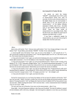
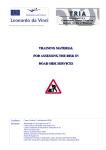
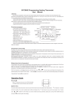
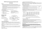
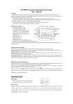
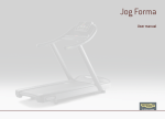
BYC01 Programmable Heating Thermostat User Manual [General Information] This thermostat is applicable to water system and electric-heated system with high power. According to the preset temperature value, thermostat will automatically start or stop the controlled object (Such as valve, heating floor, heating wall, electric heater etc). It will enable you to live in an energy-saving and comfortable living environment. This intelligent thermostat can be used either manually or automatically to meet your heating needs. The time-programmable function allows you to heat your home any time conveniently. It‟s automatic shutdown function can protect equipment from overheating, and helps you to save energy [Key Functions Description] S1 – On/Off Button (If held for more than 2 seconds) / Select Button (If held for less than 2 seconds) S2 – Down Button S3 – Up Button S4 – Switch Function Button [ Temperature control mode ] According to the sensor setting of thermostat, there are three different control modes, please enter the advance function to set. Internal control (IN): Only enable built-in sensor to temperature measurement, that the temperature control basis from the built-in temperature sensor. It is suitable for the detection of air temperature or the room temperature. External control (OUT): Only enable external sensor to temperature measurement, that the temperature control basis from the external sensor. It is suitable for the detection of the heating body temperature. Dual temperature control (ALL): Temperature control basis from the built-in temperature sensor and an external temperature sensor (over-temperature protection). It is suitable for the detection of room temperature and heating body whether over-temperature monitoring. If the external sensor is over temperature, thermostat will shuts down the heater. Operation Guide 【 Turning On 】 When “OFF” appears at the left bottom of the screen, the thermostat is being supplied with power. Press the „S1‟ button and hold for 2 seconds until the characters appear on screen 【 Turning Off 】 You can turn the thermostat off by pressing and holding the „S1‟ button until the „OFF‟ icon appears on screen. 【 Setting the time 】 Press the „S4‟ key, then the icon would flash, press „S1‟ to confirm if you are attempting to set the time You can select the day of the week, the hour and minute of the day. To do this, use the up and down „S2‟ and „S3‟ buttons, and toggle navigate between each setting using the „S4‟ button. When you are finished, press the „S1‟ button to confirm. 【 Setting temperature for times of the day 】 When you have set the time, the „Day-Phase-Setting‟ will begin. The number „1‟ will be flashing to the right of the screen, this indicates you are selecting the start time for „Phase 1‟. You can adjust the hour and minute of the start time by using „S2‟ and „S3‟, and confirming with „S4‟. It will then prompt the setting of Phase 2, which is done in the same way. You can set up to a maximum of 4 phases. If you wish not to use all 4 phases, set the time of the phase to --:--. When you have finished, the icon will flash. 【 Selecting the operating function 】 Pressing and holding the „S4‟ button will make the icon flash, continuously press „S4‟ to toggle between the settings, press „S1‟ to confirm the operating function. 【 Selecting the ‘automatic’ function 】 When the automatic function is selected, your thermostat will heat to the temperature and times you have selected in the „Day-Phase-Setting‟. You can manually increase or decrease the temperatures by using the „S2‟ and „S3‟ button. [ Selecting the ‘manual’ function ] When the manual function is selected, the settings in the „Day-Phase-Setting‟ are over-ridden. You can select the current temperature with the „S2‟ and „S3‟ buttons, which will operate continuously. [ Selecting the ‘direct heating’ function ] When the „direct heating‟ function is selected, the settings in the „Day-Phase‟ and „Manual‟ and settings are over-ridden. This will continually send power to the heating element, and should be used when heating is needed very quickly. [ Freeze protection function ] When the thermostat senses a temperature of under 5 Degrees Celsius, the thermostat will enter the heating mode until the sensed temperature reaches 8 Degrees Celsius. [ The output of thermostat ] The output of power supply. The relay contact output. [ Advanced function setting ] Warning: The advanced function setting is used to set some important parameters in the running of the system, that only for professional. Do not operate. Typically, after debugging and accurating in professionals, there is no need to set up. Enter the advanced function setting: Press the S1 to switch off the thermostat,Display will show “OFF”. Press S1 again, it will turn on. It will show “byc01”, Press Key S4 in two seconds, it will into the advanced function setting. You can press the parameters to modify settings. Select a set of content. If you do not by the or or save the data, you must go through all the functions and exit the system menu. Display AdJ Set the content Adjustment range The default value temperature correction -5℃ ~ 5℃ -2.5℃ Used to measure the error correction of the sensor, when adjusting the display correction value, 3 seconds after the display of measured correction value after the Antifreeze LtP On: Enable / OFF: Disable Low temperature protection, what is suitable for the water system OFF To prevent the pipe at low temperature was freezing. IN: Built-in Sensor or temperature control mode Sen IN:internal control, room sensor OUT: External ALL:Dual temperature control Out:external control, floor sensor IN ALL:double temperature double control, the internal room temperature sensor, external sensor overheating protecting External temperature sensor limit tOP 0.5-4℃ 1℃ 0.5-5℃ 3℃ Built-in temperature sensor hysteresis External sensor hysteresis dt1 50℃ The sensor is set to ALL, the temperature limit external sensor value Internal sensor hysteresis dt0 40-80℃ External temperature sensor hysteresis Backlighting status bL On: Always on OFF:Auto turn off after 5sec OFF Backlight lighting mode, can be set according to personal preference Status at re-power Sat OFF: off status at every time On: the same as previous, OFF Used to control the power state of the boot deF Restore factory settings Restore factory settings with the , the parameters will not modified. If you want to To restore the default settings The system menu parameters in order of appearance: AdJ ->LtP->SEn->Top->dt0->dt1->bL->Sat->dEF. The thermostat monitors display for segment LCD. There are different for the display character and practical character . [ The error and solution of common system ] 1. Fault phenomenon : There is no display Reason solution: 1、Power supply system is having problems or power is supplied incorrectly, please check if the inlet wire is normal. 2、If the connection is not right, please wired up as the wiring diagram advised on the back side. 3、Actual temperature is too low, please note the thermostat temperature range. If the temperature is lower than -5 ℃, the unit cannot normally display. 4、Power supply box and the motherboard Coupling is not connected correctly, please connect correctly. 5、Power supply box and the motherboard Coupling are opposite inserted, please mind the direction 6、Power supply box and the motherboard Coupling is broken, please don't overexert. Coupling length is 6cm, the installation must be careful. If damaged, no warranty and replacement 2. Fault phenomenon : Display rupture Reason solution: Display encounters hard objects or sudden force, no replacement and warranty 3. Fault phenomenon : Display a black screen Reason solution: If the display surface temperature is too high, please note whether there is heater nearby, if so please remove. 4. Fault phenomenon : Display ER0 or ER1 Reason solution: ER0:If built-in sensor is abnormal, please pay attention to whether the small black dot in temperature sensing window was damaged during removal ER1:The system is set in the dual temperature control (ALL) mode, or it is not connected with an external sensor, or the external sensor is abnormal. . 5. Fault phenomenon : No pen on LCD Reason solution: Please check whether the iron plate is deformation when installation. If it is deformation, please correct it. 6. Fault phenomenon : No backlight Reason solution: Please check whether backlight lamp connection is broken when removing in the panel. 7. Fault phenomenon : Backlight always bright Reason solution: 1、The ON is set in the system menu bL 2、If it is damaged, please replace it. 8. Fault phenomenon : Large deviation of measurement temperature and the actual temperature Reason solution: heater 1、The thermostat should be installed at ventilated place. It can not be installed at the place in direct sunshine or nearby the 2、Back connection screw is not locked, causing terminal serious fever 9. Fault phenomenon : Display 0 degrees Reason solution: It is normal if thermostat display 0 degrees when the actual environment is below 0 degrees. The above is some of the most common errors, if you can’t solve, please contact the local dealer! [ The Installation Method ] The thermostat should be set: about 1.4 meter height away from floor, and setting on the wall which can stand for the temperature in the room or outside. It should avoid the sun shining directly and avoid the heat appliance. The thermostat has three parts: the bottom skin, the face skin and the small box. You can open the thermostat with the screwdriver. According to the Wiring Diagram and connect the terminal and the wires of the small box. Lead to the flat able from square hole after fitting with bottom skin, then setting on the standard bottom box in the wall with M4 bolt. Connect the flat cable plug with the socket of face skin, and buckle the face skin after check over, and you can hear the sound of “CA”, it means setting successfully. No setting and remove when it with electricity. [ Product wiring diagram ] ac in:85-250v Imax 2A ac in:85-250v Imax 16A H1 WIRE DIGRAM L N [ Dimension in mm ] H3 WIRE DIGRAM N1 extra sensor 86 L L1 extra sensor LOAD 12 26 60 45 60 86 45 N ac in Relay2 To boiler SPST. ac in VALVE Relay1 Power/Lock Switch 50