1
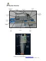
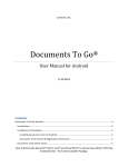
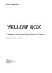
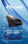
Operating Manual
Localized Electronics Cleanliness Tester
and
Residue Extractor
www.foresiteinc.com
[email protected]
(765) 457-8095
US patent #5,783,938
UK patent #2324374
China patent #ZL98107079.5
Hong Kong patent #1018313
Germany patent #19807580.4
© Foresite, Inc. 2010
Table of Contents
Table of Contents
1. CONTACTS AND CUSTOMER SUPPORT
3
2. SPECIFICATIONS & SYSTEM DESCRIPTION
2.1. Specifications
2.2. System Overview
2.3. Principles of Operation
4
4
5
6
3. INSTALLATION & PRE-OPERATION CHECKS
3.1. Shipping Contents
3.2. Unpacking & Setup
3.3. Initial System Navigation
Data Entry Touch Screen Display Options
Customer and Test Information Entry (F1) Key
Test Parameter Setup (F2) Key
Start and Stop Test (F3) Key
Data Storage (F4) Key
7
7
8
10
10
11
12
13
14
4. SYSTEM OPERATING PROCEDURES
4.1. Initial System Checkout
4.2. Standard Testing Procedure
4.3. Data Storage and Retrieval
4.4. Daily and Weekly Operational Checks
Daily Check
Weekly Check
4.5. Changing of Standard Test Parameters
4.6. System Calibration/Verification Procedures
Data Entry Touch Screen Calibration
Verification of System Current Calibration
15
15
16
20
23
23
23
24
26
26
27
5. TROUBLE SHOOTING GUIDE
28
2
Foresite, Inc. ♦ (765) 457-8095 ♦ www.foresiteinc.com
09-11-2014 – rev H
1. CONTACTS AND CUSTOMER SUPPORT
For information regarding operation, maintenance, calibration or repair of your C3,
please contact Foresite, Inc. at:
For information regarding the ordering of consumables, please go to the C3
Consumables Reorder Information at the end of this Manual.
To become fully acquainted with the operation and use of the C3, it is recommended that
personnel within your organization become active in the following ways:
•
Become a member of the C3 Users Group. Sign up at www.foresiteinc.com
or request membership via email at [email protected].
•
Receive the latest information concerning contamination issues by subscribing to
Residues News. This email newsletter contains case studies, information
concerning the C3 and information concerning other products and services
offered by Foresite, Inc. Sign up at www.foresiteinc.com or request via email at
[email protected].
•
Visit the Foresite website to receive information concerning the C3 and future
development plans. Go to www.foresiteinc.com.
3
Foresite, Inc. ♦ (765) 457-8095 ♦ www.foresiteinc.com
09-11-2014 – rev H
Contacts & Customer Support
Foresite, Inc.
1982 South Elizabeth Street
Kokomo, IN 46902
(765) 457-8095
[email protected]
www.foresiteinc.com
2. SPECIFICATIONS & SYSTEM DESCRIPTION
Specifications & System Description
2.1. Specifications
Dimensions:
28” W x 22” D x 16¼” H (71 cm x 56 cm x 41 cm)
(with arm assembly removed, the height is 13¾” H (35 cm))
Weight:
Approximately 70 pounds (32 kilograms)
Power Requirements:
100 to 240 V AC, 1 Φ
50 to 60 Hz
5.0 A @ 120 V AC
Included Components:
Micro SD data storage card
Universal USB SD card reader (for exporting data to computer)
Electrical verification cells (three cells, low, medium and high current levels)
Consumables:
Standard test cell (single use) (p/n CTC001SK)
Effective test region is 0.10 in2
Extraction solution
One (1) bag containing 1.06 quarts (1 liter)
4
Foresite, Inc. ♦ (765) 457-8095 ♦ www.foresiteinc.com
09-11-2014 – rev H
2.2. System Overview
Adjustable Arm
Assembly
Arm Locks
Test Cell
Ejector
Steam Head
Test Cell
Placement on
Sample
Unitronics
PLC
Extraction
Solution
Fluid System
Drawer
ESD Mat
Power
Switch
Storage
Drawer
Steam
inlet
Vacuum
outlet
Electrode
Wing
Sample
collection
reservoir
Seal
5
Foresite, Inc. ♦ (765) 457-8095 ♦ www.foresiteinc.com
09-11-2014 – rev H
2.3. Principles of Operation
The information gathered when using the C3 is intended to provide
a measure of the cleanliness of a localized region of a circuit board.
In addition, the C3 extracts a sample of the effluent from that
localized region that can be used in further ionic analysis (such as
ion chromatography).
The C3, in conjunction with the extraction solution, has been
designed to achieve effective ionic residue removal using a heated
delivery system that consists of 3 stages:
1. Heat the extraction solution and deliver to the extraction site
2. Soak to allow solubilization of ionic species
3. Aspirate the solution into a collection cell
This process cycle is repeated nine (9) times to allow effective
removal of the surface contaminating residues from a region of
about 0.1 in2. The extracted ionic residues are then collected for
subsequent analysis. The nine cycles should produce a volume of effluent that will fill
the cell reservoir to a level where the meniscus of the liquid falls between the solder
mask regions of the test cell (see arrow in figure below)
Simple “Clean” / “Dirty” analysis is performed using the C3 on-board
measurement system. If more detailed analysis of residues is required,
the extracted solution can be analyzed using more sophisticated
techniques such as ion chromatography.
The C3 on-board measurement system uses a sacrificial circuit board
electrode, immersed in the extracted solution, to measure the electrical
conductivity of the solution. By applying a known bias (10 volts) across
the electrode terminals, a leakage current between the traces can be
measured.
Using the results from both SIR (surface insulation resistance) and ion chromatography
testing, a leakage current of 250 µA has been established to identify when a current
leakage event has occurred.
The design of the C3 assumes that the more corrosive or conductive the extracted
residue, the quicker a current leakage event occurs. The less corrosive or conductive
the residue, the longer it will take to reach a 250 µA event.
The C3 system measures the time taken to reach a 250 µA current leakage event.
Extensive testing has shown that C3 timing results that achieve the 250 µA event in less
than 120 seconds correlate to residues that exceed the ionic contamination limits set
forth by Foresite, Inc. Such results are identified as unacceptable and that region of the
circuit board is considered “Dirty”. Timing events that take longer than 120 seconds to
achieve a 250 µA current leakage event correlate to acceptable residue levels and that
region of the board is considered “Clean”.
6
Foresite, Inc. ♦ (765) 457-8095 ♦ www.foresiteinc.com
09-11-2014 – rev H
3. INSTALLATION & PRE-OPERATION CHECKS
3.1. Shipping Contents
C3 system with integrated Unitronics PLC model V350
Detached movable arm
Micro SD storage card (2 GB) - containing operating system software
Micro SD storage card to USB adapter
Electrical verification cells (high, medium and low current levels)
Dust cover cell
Roll of Kapton tape
Power cord
Operating Manual
Allen wrenches (5/64” for steam head; 3/32” for access panels)
Standard test cells (one box, 100 per box)
Extraction vials - 2 mL (one box, 100 per box)
Caps for vials (one bag, 100 per bag)
Extraction solution (1 liter)
PDA stylus
7
Foresite, Inc. ♦ (765) 457-8095 ♦ www.foresiteinc.com
09-11-2014 – rev H
Installation & Pre-operation Checks
•
•
•
•
•
•
•
•
•
•
•
•
•
•
•
3.2. Unpacking & Setup
1. Remove all components from the shipping container.
2. Remove the wing nut and washer from the stationary post.
3. Insure the white spacer washer is centered on post. Place
the movable arm on stationary post as shown. Place
metal washer on arm and screw the wing nut down to
secure the arm to the post. Adjust the tightness of screw
to control the ease of arm motion.
4. Connect the electrical, vacuum and water supply
lines behind the test arm base.
• The electrical connection for the test head is a
keyed barrel connector. Rotate the connector
until the keyed position is found. Insert to full
depth and rotate locking barrel.
• The vacuum connection is made with a push
and click motion. When the fitting is fully
seated, the retention clip will snap into place.
• Thread the extraction solution tubing assembly
into the base fitting. Twist the fitting until finger
tight.
5. Attach the power cable to the connector on the back panel
of the cabinet.
8
Foresite, Inc. ♦ (765) 457-8095 ♦ www.foresiteinc.com
09-11-2014 – rev H
6. Remove the shipping cap from the extraction solution
bag and replace it with the system one-way valve cap.
(It is necessary to remove the solution feed line from the
system cap first.) Burp any air bubbles that are trapped
in the solution bag by holding the bag upright and
squeezing out the trapped air. The one-way valve will
keep air from re-entering the bag.
7. Replace the system feed line by hand tightening
the fitting to the one-way valve. Lay the solution
bag on the side in the fluid system drawer as
shown.
8. Plug the power cable into a 100 - 240 V power outlet. Turn the unit on
using the power switch located on the left side of the cabinet. The unit
should be operational at this point.
9. Upon power up, two temporary
screens appear. First, the Unitronics
black and white boot screen
appears, this is followed by a
Foresite/C3 boot screen showing the
progress of the operating system
boot process. Upon completion of
these boot screens, the system
opens to the Test Homepage Screen
as shown.
10. If this boot process does not occur
and this Test Homepage does not
appear, refer to Troubleshooting
Guide later in this document.
9
Foresite, Inc. ♦ (765) 457-8095 ♦ www.foresiteinc.com
09-11-2014 – rev H
3.3. Initial System Navigation
The C3 is operated by selecting one of five function keys on the PLC control panel.
Those function keys control the system as shown below.
The five functions keys are:
• F1 key - Customer and Test Information Entry Screen
• F2 key - Test Parameter Setup Screen
• F3 key - Starts and Stops Test Screen
• F4 key - Data Storage Screen
• ESC key – Returns to Test Homepage
Detailed descriptions of the function keys follow, starting on the next page.
Data Entry Touch Screen Display Options
Multiple data entry touch screens are available to allow custom fonts and foreign
language characters to be added to data screens. These screens are accessed using
the arrows in the upper left hand corner of the entry screen.
Standard upper case English touch screen
Lower case
Special case
Foreign upper and lower case
10
Foresite, Inc. ♦ (765) 457-8095 ♦ www.foresiteinc.com
09-11-2014 – rev H
Customer and Test Information Entry (F1) Key
Function key F1 allows entry of customer and test information into the test database.
Two screens of information are available for data entry. The left screen appears first
with detailed comments being added by accessing the comment screen. The OK
buttons move the program back to the previous page or to the Test Homepage.
To change a data entry field, tap (with your finger or the stylus) that data field and the
data entry touch screen will appear. Enter data as needed. To clear data use the CLR
button.
11
Foresite, Inc. ♦ (765) 457-8095 ♦ www.foresiteinc.com
09-11-2014 – rev H
Test Parameter Setup (F2) Key
Function key F2 allows for the inspection of and changing of the default C3 system
parameter settings. Multiple setup screens are accessed from this screen using
password control. Descriptions of those screens are discussed in the Adjustment of
Standard Testing Parameters Section of this manual.
In addition to parameter settings, calibration/verification procedures are accessed from
this screen (go to the System Calibration Procedures Section of this manual for detailed
information). The extraction solution heater may be turned on and off at this screen, as
well as determining the version of the operating system.
Return to Home Screen button moves program to the Test Homepage.
12
Foresite, Inc. ♦ (765) 457-8095 ♦ www.foresiteinc.com
09-11-2014 – rev H
Start and Stop Test (F3) Key
This function key is only used to START and STOP a C3 extraction test. From this
screen, it is possible to review the customer information data prior to starting a test.
The Save Data button saves the data to the PLC flash memory data log.
The Purge button brings up a setup screen that is used to control purging of the system.
The Next Test button indexes the test number. Note, the initial test number must be set
at the Customer and Test Information Entry Key (F1)
To start a test, press the F3 button. To stop the test, press the F3 button.
The Purge screen provides the controls necessary to test and purge the solution
extraction system. The number of purge cycles is set to one hundred and fifty (150) at
the factory. This number is user definable, if needed. Pressing the Purge (X) button will
cause the system to purge that set number of cycles. The heater on/off button provides
a second location where extraction solution heating is controlled.
13
Foresite, Inc. ♦ (765) 457-8095 ♦ www.foresiteinc.com
09-11-2014 – rev H
Data Storage (F4) Key
Function key F4 is used to access and save the data that is collected during C3 testing.
Three screens make up the major entry points where data storage is performed. Using
these screens, two types of data can be downloaded to the MicroSD card that is
installed in the PLC.
The two types of data are:
•
Data Log - this data file contains the
test parameter data, the customer
information data, time stamp and
results reported as “pass” or “fail”.
This data is stored as a binary file and
cannot be read without proprietary
software.
•
Detailed Data - this file contains every
data point (time and current) taken
during the test. This data file is stored
as a comma separated values (CSV)
file and can be read by Microsoft
Excel. Using this data file, the actual
test data plot can be reconstructed.
Data Log manipulation screen
Detailed Data (CSV) manipulation screen
14
Foresite, Inc. ♦ (765) 457-8095 ♦ www.foresiteinc.com
09-11-2014 – rev H
4. SYSTEM OPERATING PROCEDURES
4.1. Initial System Checkout
1. Insure that the steps prescribed in the Unpacking & Setup Section of this manual
have been performed and that when the unit is turned on, the Unitronics PLC is
displaying the Test Homepage screen.
3. Insert a test cell into the steam head as shown.
Raise the head and with the collection reservoir
facing the front of the head, push the test cell up in
the head using the base of the reservoir until the top
of the wings is in line with the steam head housing
(see arrow in photograph at right).
4. Standard practice suggests handling the cell only by
the wings.
5. As a standard practice, the extraction solution delivery system is purged one
hundred and fifty (150) times prior to actually placing the C3 in a production
environment. From the Test Homepage press the PURGE button to enter the
Purge Menu screen. As the number of purge cycles is set to 150 at the factory, the
system is initially setup to perform this procedure. Press the PURGE (X) button to
start the process. Collect the purged solution by placing a beaker under the steam
head.
6. As a way to insure that the system electrical calibration has not been affected during
shipping, a verification of system current calibration is to be performed prior to
actually placing the C3 system in a production environment (see the System
Calibration/Verification Procedures Section of this manual). This verification consists
of determining the actual measured current when each of the three Electrical
Verification Cells (low, medium and high) is placed in the steam head.
The resulting measured current values must fall within the limits set forth in the
verification procedure. If the values fall outside of those limits, contact Technical
Support at Foresite, Inc.
15
Foresite, Inc. ♦ (765) 457-8095 ♦ www.foresiteinc.com
09-11-2014 – rev H
System Operating Procedures
2. Verify that the extraction solution bag has a sufficient quantity of liquid and has been
“burped” to remove any trapped air bubbles. Position the bag so that any remaining
bubbles float away from the liquid outlet.
4.2. Standard Testing Procedure
After the extraction solution system conditioning (purging) and the electrical verification
testing are successfully completed, the C3 is ready to be placed in a production
environment.
Foresite recommends the use of an ESD strap when working with components or
assemblies that may have highly sensitive static areas. The C3 is equipped with a
common ground location for convenience.
The C3 can be user configured to meet any particular extracting/testing condition that is
desired. However, extensive field and laboratory experience has established a standard
set of testing conditions to be used for the vast majority of situations. Those standard
parameters are loaded into memory at the factory.
The following table lists the testing parameter sets for the Standard test cell and the
smaller 0805 test cell.
Standard C3 Extraction/Testing Parameter Sets
Parameter Name
Area of extraction (inch2)
Total Test Time (sec)
Check Current Time (sec)
Limit Current (µA)
Cycles per Test
Preheat Temperature (ºF)
Solution Heater Temperature (ºF)
Pump Control - count
Pump Control - time on (msec)
Pump Control – time off (msec)
Vacuum Time (sec)
Soak Time (sec)
Standard Test Cell
0805 Test Cell
P/N CTC001SK
P/N CTC011SK
0.10
180
120
250
9
210
255
7
300
700
2
20
0.02
180
120
250
65
210
255
1
300
700
2
2
future parameter set
Detailed instructions concerning changing the standard parameters are provided in the
Adjustment of Standard Testing Parameters Section of this manual. The changing of
these parameters is under password protection.
1. Prior to beginning testing, the system must be
allowed to warm up and stabilize. Turn on the
extraction solution heater using the Heater button in
the Test Parameter Setup screen (F2).
The red light on the steam head indicates that the
heater is turned on. The light will first blink then stay
on and finally begin to cycle once the heater is at
the desired temperature. The heater will take
several minutes to reach the set point temperature.
16
Foresite, Inc. ♦ (765) 457-8095 ♦ www.foresiteinc.com
09-11-2014 – rev H
Upon initially turning on the system, the heater temperature is set to the system
preheat temperature. At the start of the first test, the heater temperature changes to
the solution heater temperature and stays at that temperature until the system is
turned off and then restarted. Again, the heater will take several minutes to reach
the desired extraction temperature.
2. Prior to starting a test, customer information must be inputted into the system
database. This operation is accessed with the F1 function key.
3. Place the sample to be tested on the ESD mat in such a location that the area-ofinterest is within reach of the steam head.
4. Remove a test cell from the shipping rack, handling only by side wings on the cell.
Install the test cell as discussed previously. It is important that the cell be fully
seated up into the steam head.
5. Lower the steam head with the test cell to the area
to be tested. Make sure that the red seal is fully
compressed.
6. Begin the test process by pressing function key F3.
During testing the following screen is visible. A
number of key parameters are displayed during this
process.
As shown, the temperature of the extraction solution heater is displayed (Temp(F)).
As the extraction process continues, the Status data line will change based on which
phase of the extraction process is occurring. The extraction process will repeat the
specified number of cycles as shown at Cycle.
A variety of error codes may display across the bottom of the screen if the system is
not functioning properly. If an error code is displayed, go to the Trouble Shooting
Guide Section of this manual for a list of possible corrective actions.
7. As the test progresses, the measured current at each measurement interval (250
msec) is plotted. Three result conditions are possible during testing. Those
conditions are Clean, Dirty and Invalid. The two most likely outcomes are CLEAN
17
Foresite, Inc. ♦ (765) 457-8095 ♦ www.foresiteinc.com
09-11-2014 – rev H
and DIRTY. In the case of the clean event, the measured current did not exceed the
specified Limit Current (µA) within the Check Current Time (sec). In the case of the
dirty event, the specified Limit Current (µA) was exceeded in less than the Check
Current Time (sec).
The third result condition (INVALID) is most likely caused by a solution extraction
error. In this case, the volume of liquid extracted up into the collection reservoir was
not large enough to have the meniscus of the solution fall within the upper open
region of the test electrode (see photograph in Principles of Operation). If this occurs
on a clean sample, the current will be less that about 70 µA triggering an INVALID
test condition.
If this low liquid level event occurs on a highly contaminated sample, the 250 µA
event limit will probably occur and the result will report as dirty.
There are two likely reasons for a low liquid level. First, if open vias are present
within the test region, the extraction liquid will flow out the backside of the circuit
board. This is usually taken care of by applying Kapton tape to the backside of the
board sealing the vias. Alternatively, the seal on the cell may be incomplete allowing
liquid to leak out onto the top surface of the board.
8. At the completion of a test, it is necessary to save the data to the test database. If
this step is not completed, a record of that test will be lost. Press the Save Data
button to store the current test data.
Raise the steam head and push down on the ejector bar to release the test cell.
Remove the cell by pulling down on the wings of the cell.
9. In some cases, the collected sample is to be further
analyzed using ion chromatography or some other
chemical analysis test technique. In this case, snap
off the retaining cap from the top of the test cell and
transfer the sample to a clean sample bag or vial.
Care must be taken to not contaminate the vial or
the vial cap by touching the rim or cap seal with bare
hands.
18
Foresite, Inc. ♦ (765) 457-8095 ♦ www.foresiteinc.com
09-11-2014 – rev H
10. The majority of the extraction liquid is taken up into the collection reservoir during
testing leaving little liquid left on the test assembly. Therefore as a general
statement, the part under test is left to air dry with no attempt to actively force clean
or dry the tested region. If desired, the surface can be dried using a clean
AlphaWipe lint free cloth.
11. When this testing process is completed another test may be started. It is important
to index the test number (press Next Test) prior to starting the test. The test number
does not auto index!
19
Foresite, Inc. ♦ (765) 457-8095 ♦ www.foresiteinc.com
09-11-2014 – rev H
4.3. Data Storage and Retrieval
It is important to note that data storage is not automatic.
In order to keep a log of the testing that was conducted and of those results, it is
necessary to save the results of each test before starting a new test. If a new test is
started before the data is stored, the results of the previous test are purged from
memory.
Data is stored in two steps, first the data must be saved to the flash memory within the
PLC. The flash memory has capacity for two hundred (200) tests. This data file is called
the Data Log. Saving data to the flash memory is accomplished using the Save Data
button on the Test Homepage screen or the Save Data to PCL Log button on the File
Menu screen (press the F4 key).
The second operation is to transfer the data that is stored in flash memory to the
MicroSD card. This is accomplished at the Data Log manipulation screen. At the File
Menu screen (F4) press the Data Log button to access the following screen.
At this screen it is possible to view the entries in the Data Log (press the View PLC Data
Log button). Using the Next Screen and Last Screen and Up and Down buttons it is
possible to view all portions of the Data Log file. It must be remembered that this is the
data that is stored in the PLC flash memory.
Several decisions must be made prior to data being copied to the MicroSD card. First
the directory where the data is to be stored must be determined. The DT button allows
five (5) directories and subdirectories to be selected. The DT directory is the root
directory and under that four (4) subdirectories are available.
The form of those directories is:
DT (root directory)
DT/DT1 (subdirectory 1)
DT/DT2 (subdirectory 2)
DT/DT3 (subdirectory 3)
DT/DT4 (subdirectory 4)
20
Foresite, Inc. ♦ (765) 457-8095 ♦ www.foresiteinc.com
09-11-2014 – rev H
The next decision is the file name for the Data Log. That name is added by pressing the
Log File Name button and entering the name at a data entry touch screen. After the
directory and file name have been selected and entered, press the Save PLC Log File
to SD Card button. All test data that was saved in the flash memory is now transferred
and saved on the MicroSD card.
It is assumed at this point, that a new set of tests has started (new circuit board, new lot
number, new project, etc.). This will probably mean starting a new Data Log with that
most recent set of test conditions. Therefore, the existing data in the flash memory Data
Log must be deleted. Use the Clear PLC Log button to delete that previous data set.
(Notice that both the Save PLC Log File to SD Card and the Clear PLC Log buttons
must be held down for five (5) seconds to complete this action.
At this point the Data Log has been saved to the MicroSD card in a proprietary binary
data file format (the file extension is *.UDT). To be able to read, printout or archive the
Data Log, a file conversion program must be loaded onto a host PC. That executable
program is provided on a CD in a sub directory labeled Unitronics SD Suite. Double
clicking on the setup file will auto load that program suite onto the host PC.
Instructions on using this program suite are beyond the scope of this document.
Please contact Technical Support at Foresite, Inc. if assistance is needed in running this
windows-based program.
As discussed previously, there is a second data format (Detailed Data) that may be
saved after each test run. In this case, the individual data points (current and time) are
appended to the previously stored tests in a comma separated values (*.CSV) file
format. As this data is stored as CSV, Microsoft Excel is able to read the data file
directly. This data format is useful if there is a need to reconstruct the actual time vs.
test current data plot.
To save detailed data, enter the detailed data page by pressing the Detailed Data
button on the File Menu Screen (F4) page. From the following page, detailed data is
manipulated and saved. To save the detailed data press the Save Detailed Data to SD
Card button.
21
Foresite, Inc. ♦ (765) 457-8095 ♦ www.foresiteinc.com
09-11-2014 – rev H
The Detailed Data file architecture is similar to the Data Log file architecture. In this
case, the root and sub directory names are EXCEL rather than DT.
The form of those directories is:
EXCEL (root directory)
EXCEL/EXCEL1 (subdirectory 1)
EXCEL/EXCEL2 (subdirectory 2)
EXCEL/EXCEL3 (subdirectory 3)
EXCEL/EXCEL4 (subdirectory 4)
Similar comments are made concerning naming the file and when to start a new file.
When the Detailed Data file name is changed and new data is added, the CVS Detailed
Data file resets, clearing all previous data entries. Subsequent tests when saved will
append to the end of that CSV file. It is recommended that the file name of the Data Log
and the file name of the Detailed Data be the same name. In this way, it is possible to
find and compare the data between those two data files.
At the present time, the only way to gain access to the saved data files is by removing
the MicroSD card from the Unitronics PLC and using a standard USB card reader. The
location of the card slot is on the right side of the housing as shown below.
As the MicroSD card is very small and the recess is quite deep, it is suggested that the
card be placed into the PLC card slot using a pair of tweezers. Notice the card is placed
in the slot with electrical leads facing up. Once the card has been placed in the slot,
press the card fully into the slot using a finger until the card clicks in place.
Cautionary note
The MicroSD card contains the operating system, as well as the data files. Do
not attempt to format the MicroSD card, as the operating system will also be lost.
Use standard Windows protocol to manipulate, copy and move the data files from
the MicroSD card.
22
Foresite, Inc. ♦ (765) 457-8095 ♦ www.foresiteinc.com
09-11-2014 – rev H
4.4. Daily and Weekly Operational Checks
Daily Check
It is recommended that the solution extraction system be reconditioned each morning
prior to the running production tests.
1. From the Test Homepage Screen select the Purge button.
2. From the Purge Menu select the Purge(X) button and purge the system into a
beaker for 150 cycles as was done during the Initial System Checkout.
This purge operation should insure that the extraction system will provide very low
contamination extraction solution thus providing the most repeatable test results.
Weekly Check
It is further recommended that the current measurement calibration be verified weekly.
Again this test is the same test conducted during the Initial System Checkout.
Follow the procedure for Verification of System Current Calibration in the System
Calibration/Verification Procedures Section of this manual.
23
Foresite, Inc. ♦ (765) 457-8095 ♦ www.foresiteinc.com
09-11-2014 – rev H
4.5. Changing of Standard Test Parameters
It may be necessary to change the standard test parameters due to specific concerns,
modified test cells or customer requirements. From the Test Parameter Setup screen
(F2), select the Settings button. This will bring up the Enter Password screen. Tap the
center field and this will bring up a Data Entry Touch Screen. Type the password
provided at the time of purchase, then press the OK button.
The following screen allows the changing of the most commonly modified test
parameters. After entering the changes, press the OK button to accept those changes.
This will take the program back to the Test Parameter (F2) screen.
Additionally, pump parameter setting may need to be changed to accommodate other
test cell geometries. If these changes are needed, re-enter the Test Parameter Setup
screen as above. Now, press the Advanced Settings button, to bring up the Advanced
Machine Settings screen (see next page). Press the Next Screen button to bring up the
pump parameters screen (see right hand screen below). Make changes as needed then
press OK to save the settings and return to the Test Parameter (F2) screen.
24
Foresite, Inc. ♦ (765) 457-8095 ♦ www.foresiteinc.com
09-11-2014 – rev H
Cautionary Note
Under no conditions should the Gain, Integral or PWM cycle (sec) parameters ever be
changed by the end user. Changing these values will affect the calibration of the
system.
25
Foresite, Inc. ♦ (765) 457-8095 ♦ www.foresiteinc.com
09-11-2014 – rev H
4.6. System Calibration/Verification Procedures
Data Entry Touch Screen Calibration
The data entry screen may need to be calibrated to allow accurate selection (location) of
entry keys. Enter this calibration process from the Test Homepage screen by pressing
and holding down the touch screen for five (5) seconds. This will bring up an entry
screen as shown. Press the Calibrate Touchscreen pad to bring up a series of screens
with small squares at each corner. Touch the center of each square as each screen
appears. When all five (5) squares are touched, the screen calibration is completed.
Press the ESC pad to return to the Test Homepage.
26
Foresite, Inc. ♦ (765) 457-8095 ♦ www.foresiteinc.com
09-11-2014 – rev H
Verification of System Current Calibration
The accuracy of the measured sensor current can be verified using the three electrical
verification cells supplied with the C3. Those cells are matched to the serial number of
the supplied unit. The results of this verification should produce current values within the
range shown in following table.
Cell
Designation
Minimum
Current (µA)
Low
Medium
High
209
450
662
Maximum
Current (µA)
219
460
672
Insert each test verification cell into the steam head and press the Force 10V button.
The state of that button should indicate ON. When the voltage is applied, the Current at
the Electrode (µA) window should read a value between the limits in the above table.
If all three current values fall within the specified limits, the system is considered
calibrated and acceptable for production use.
When this testing is completed, insure that the Force 10V button is in the OFF state.
27
Foresite, Inc. ♦ (765) 457-8095 ♦ www.foresiteinc.com
09-11-2014 – rev H
5. TROUBLE SHOOTING GUIDE
Problem One – Amber power switch light is not lit.
1. Check that the power cord is properly connected to the power source.
2. Check that supply power is present.
3. Check the main power fuse. The main power fuse (and a back-up fuse) are
located at the back of the machine at the power receptacle. Open the access
panel as indicated below to access the fuses.
Problem Two – PLC will not boot to the Test Homepage Screen
1. The program has been lost or is corrupted. Contact Technical Support for
assistance in reloading the operating system.
Problem Three – Current reading is nearly 0 (less than 70µA) during the entire test
1. Check that the level of extracted solution in the electrode reservoir falls within
the upper open region of the cell (see arrow in Principles of Operation cell
photograph). If level is correct, contact Technical Support. If level is low,
proceed to step 2.
2. Check the amount of extraction solution in the bag of the fluid delivery
system. If level is low, replace with a new bag. If there is sufficient solution
in the bag, proceed to step 3.
3. Check to ensure extraction solution is not escaping past test cell end seal or
through test sample during the test cycle. If not leaking, proceed to step 4.
4. Ensure that the test cell is properly seated in the steam head. The wings on
the cell should be in line with the housing as shown in the Initial System
Checkout section, item 3. If properly installed, proceed to step 5.
5. If the condition is not resolved, contact Technical Support.
Problem Four – Test does not start – Heater Disabled appears in test screen
1. The heater is not enabled (turned on). Go to the Test Parameter Setup (F2)
screen and press the Heater is Off button. This should change the state of
the button to On and the button should change to green. The heater should
begin to heat the steam boiler. This will take several minutes to get to the
preheat temperature. When the F3 button is pressed, it will take another
several minutes to get to the Solution Heater Temperature. Only when that
temperature is reached will the test begin.
2. Alternatively, press the Purge button on the Test Homepage and again turn
the heater on at the Heater is OFF button. Same process applies as in step
1 above.
28
Foresite, Inc. ♦ (765) 457-8095 ♦ www.foresiteinc.com
09-11-2014 – rev H
Trouble Shooting Guide
4. If this condition is not resolved, contact Technical Support.
Problem Five – Need to know the C3 operating system software version.
1. Press function key F2, then press the C3 O.S. version button.
2. This screen will display the installed version of C3 software.
Problem Six – Getting Error message: Cannot start test because thermocouple is
not operational
1. The electrical connector is not properly seated and locked into place. Refer
to Section 3.2.4 concerning attaching the cable and hoses during setup.
Reseat the connector insuring full engagement and lock.
2. Thermocouple wire has broken somewhere within the system. Contact
Technical Support concerning this failure.
Problem Seven – Getting Error message: !! Temperature too high !! and an audible
beep
1. There is a thermocouple or logic error. Continuing to operate the system will
do damage to system. Turn system off and contact Technical Support
concerning this failure
Problem Eight – When saving the Data Log, get error message: Memory full.
Unable to save data
1. The PLC flash memory is full. Two hundred tests have been run without
saving data to MicroSD card. If data is not needed, clear the PLC log (see
Section 4.3). If data is needed, select a directory and subdirectory, name the
file and save data to PLC Log file on the MicroSD card (see Section 4.3).
Problem Nine – When performing Verification of System Current Calibration – all
values did not fall within the limits listed in the table on page 27.
1. The temperature calibration of the system is out of specification. Contact
Technical Support concerning this failure.
If any problems are encountered, other than those listed above, please contact
Technical Support at (765) 457-8095 or [email protected].
29
Foresite, Inc. ♦ (765) 457-8095 ♦ www.foresiteinc.com
09-11-2014 – rev H