1
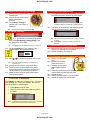
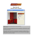
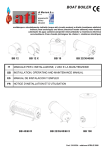
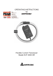
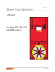
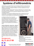
actoolsupply.com QuickGuide-Blower Door-QMG 3 Gauge Fans must be plugged into three separate circuits! Read and experiment with each step To perform automatic or multi-point tests*, refer to the FanTestic Software Manual and the DM-2 Operator’s Manual *Tests for CGSB 149, LEED, ASTM E778, ASTM 1827, EN13829, and ATTMA TS-1 may require more elaborate steps and training. This guide is 1 Setup the DM-2s 2 Set up the building 1.1 2.1 2.2 Setup the DM-2s as needed for the required testing standards QuickGuide-DM2MkII 2.3 Ensure that rechargeable batteries are fully charged (may take eight hours or more), or that spare batteries are available for each gauge. 2.4 2.5 See: 1.2 Close the outside doors and windows. Open all interior doors leading to conditioned spaces. Shut off HVAC (exhaust fans, dryers, A/C, furnaces). Turn gas hot water to pilot. Place paper over any open ashes. Close all windows Retrotec US3212 Blower Door System Retrotec US3211 Blower Door System QG320 Page 1 of 6 actoolsupply.com Gas valve to Pilot Cover ashes with paper rev-2011-10-10 actoolsupply.com 3 Unpack the fan panels 7 Install the cross braces 3.1 3.2 7.1 Slide a locking collar and retention strap onto each end of the cross braces. 7.2 Take one cross brace and slide the flat end between the door and frame. 7.3 Attach the bolts from both retention straps to the top section of the panel. Tighten the retention straps and align the cross brace and white ring so that the panel is held tightly. 3.3 Remove the 3-Fan panel from the case. Stand the panel on its side, and unfold the sections. Lock both panel sections using the butterfly latches (which are opposite the hinges). 4 Position the panel 4.1 4.2 4.3 The panel must be placed so that the fan holes are on the same side as the door hinges. The door should open in the opposite direction from the panel. Secure the door open. The panel side which displays “Retrotec” must face towards the operator. 7.4 5 Secure the fan panel 5.1 5.2 5.3 Attach a retention strap to the top corner of the frame, nearest the door hinges. Pull the anchor over the door, and in between the door and frame. Tighten the strap until the panel is tight against the door frame. 7.5 7.6 8 Install the corner brace 8.1 6 Attach the fan straps 6.1 Attach the three fan straps, one for each fan hole. Secure the white ring in place by using the locking collar to pin the ring against the door frame. Attach the second cross brace to the lower section and repeat 7.2 - 7.5. 8.2 8.3 8.4 8.5 Install the corner brace in the top corner, on the opposite side of the door frame from the hinges. Attach a retention strap to the door panel. Slide the corner brace through the white ring. Place the corner brace at a diagonal across the corner of the door frame. Tighten the retention strap. Page 2 of 6 actoolsupply.com actoolsupply.com 9 Seal any remaining gaps 11 Connect the fan umbilical 9.1 11.1 Connect each fan to one of the variable speed drives with the umbilical that is attached to the drive. 11.2 Connect the grey 230V Output cable from the drive to the 230V Input port on the fan top. 11.3 Connect the yellow and green pressure tubes to the two ports on the fan top. 9.2 Depending on the height of the doorway, a gap may be left open between the top of the panel and the door frame. Use grill mask to seal the gap. 10 Install the fans 10.1 Remove the fans from their cases. 10.2 Install each fan in the panel by seating the base of the fan into the panel. 10.3 Align the notch on the top of the fan with the gap in the fan panel. Slide the notch through the panel. 10.4 Rotate the fan slightly so that it rests securely in the fan panel. 10.5 Attach the fan strap to hold the fan in place. Variable speed drive Fan top 12 Connect DM-2 #1 to Drive 12.1 Connect the red, yellow, and green tubes from the umbilical to the DM-2. Connect the yellow Ethernet control cable to the DM-2. 12.2 Connect the yellow and green tubes (at the other end of the umbilical) to a variable speed drive unit. 12.3 For manual fan control, connect the yellow control cable to any port on the splitter box. To use FanTestic software, connect the control cable to the drive unit. Note All ports on the splitter box function in parallel. There are no designated input and output ports. optional Splitter box 12.4 The remaining long red tube goes through the small hole in the bottom of the door panel. Ensure the tube end is out of the way of the fan air flow. Note The fan speed control cables are standard Ethernet cat 5 cable. However the devices will not work if connected to the Internet or to a laptop. Page 3 of 6 actoolsupply.com actoolsupply.com 13 Connect the variable speed drives 15 Begin automatic test 13.1 Plug each drive into a 20 amp outlet (not GFCI), on an independent circuit, to avoid tripping the breaker. 15.1 If using FanTestic software, begin the test at this point. 15.2 Follow the instructions as laid out in the FanTestic User Manual, or as they appear on screen. 15.3 If conducting the test manually, continue on to step 16. Tip A stove outlet is usually on an independent circuit. 13.2 Connect each drive unit to any port on the splitter box using the control cables if manually controlling fan speed. 16 Zero gauges 16.1 Press [Auto Zero]. When “On” is displayed, the gauge will zero itself every 8 seconds. 16.2 This needs to be done on all gauges. Tip 14 Connect DM-2 #2 and #3 14.1 Connect DM-2 #2 and #3 to the remaining two variable speed drives. 14.2 Connect the yellow and green tubes between Channel A of DM-2 #2 and Drive #2. 14.3 Connect the yellow and green tubes between Channel A of DM-2 #3 and Drive #3. 14.4 If fan control will be handled through FanTestic software, connect the control cables directly to the drive units, as shown on the first page. Normally, Auto Zero should be left “On”; turn off to save battery power. 17 Set time averaging 17.1 Press [Time Avg] as needed, until “PrA” varies by less than 1Pa. Windy conditions will require a longer time averaging. 17.2 Wait for twice the time average setting before taking a reading. Tip 1s, 2s, 4s, 8s updates every 1 second(s), 10s, 20s, 1min, 2min updates every 10 seconds. 18 Measure bias pressure 18.1 Prior to each test, with the fans covered, press [Baseline] on all gauges to begin averaging the bias pressure. 18.2 Press [Enter] after about 60 seconds to capture the bias pressure reading. 18.3 After each test, press [Exit] to clear the baseline. #2 #3 Note The value displayed under “Baseline” will offset the influence of bias pressure on the pressure reading. 19 Set fan model on DM-2 19.1 Press [Device] on DM-2 #1 until “Retrotec 3000SR” is displayed. 19.2 The 3000SR fan model has two pressure tubes attached. If there is no reference port on the fan, set the Device to “Retrotec 3000”. See: DM-2 control setup for common fan control Page 4 of 6 actoolsupply.com QuickGuide-DM2MkII actoolsupply.com 20 Remove fan cover and set range 22 Set pressure automatically 20.1 Remove the fan covers from all three fans. 20.2 All three fans should be open, with all range plates removed. 20.3 Press [Range Config] on DM-2 #1 only, until “Open” is displayed. 22.1 Press [Set Pressure] [10-90] [Enter]. The DM-2 will control the fans to achieve the set pressure. See: Example: Press [Set Pressure] [50] [Enter] to instruct the DM-2 to attempt to achieve 50Pa building pressure. 22.2 The DM-2 will automatically adjust the fan speed until the desired pressure is achieved. QuickGuide-Fan-RangeConfig-2000&3000 21 Set speed manually 21.1 On DM-2 #1 (connected to the splitter box), press [Set Speed] [10-100] [Enter] to set any speed from 10 to 100%. Tip Press [Exit] or set the speed to zero to turn the fans off. Tip Tip Click once to change pressure by 5 Pa, hold to increment by 10 Pa. Press [Exit] to turn the fans off and cancel the “set pressure”. 23 Pressurization testing (optional) 21.2 Press [Jog/Hold] until “Jog” appears. This enables manual fan speed adjustment. 23.1 Remove the fans from the door and install them so that they are blowing into the building. 23.2 Repeat procedure from Step 15. 21.3 Use [] [] to adjust the fan speed up or down. 24.1 Insert a T in the yellow tube. 24.2 Connect the red and yellow ports to the T. 24.3 Increase the fan speed and compare PrA and PrB. 24.4 Disconnect tubes from yellow and red ports and connect them to green and blue ports. 24.5 Repeat the test. 24.6 Values should be within 1% of each other. 24.7 Repeat the test for the second DM-2. 24 Field gauge check recommended weekly Tip Click once to change speed by 1%, hold button to increment by 5%. 21.4 All three fans should run at the same speed. 21.5 Adjust the fans’ speed to achieve the lowest required test pressure. Check to see if the flow can be measured on Channel B of DM-2 #1. 21.6 Adjust the fans’ speed to achieve the highest required test pressure. “TOO LOW” is displayed Press [Mode], on DM-2 #1, to display “Flow”. If PrA has been reached, but “TOO LOW” appears, the fans are running too slowly to measure flow. 1. Press [Exit] to stop the fans. 2. Remove one fan and install a blanking plate in the panel. 3. Restart the fans and try again. Note The displayed flow is the flow for Fan #1 only. It is not the reading of the combined flow for all three fans. Page 5 of 6 actoolsupply.com actoolsupply.com 25 Setting up a 6-Fan system 27 Connect the fans to the splitter box 25.1 If additional airflow is required, six fans can be connected and controlled together. 25.2 Connect two three-fan panels using the Connector Plate. The fan holes should be oriented towards the middle. 27.1 Connect each fan to a variable speed drive. 27.2 Connect all six speed drives to the same splitter box. 25.3 The panels must be placed opposite the direction the doors open. 26 Securing the 6-Fan system 26.1 Secure the panels using the retention straps, by placing the anchors through the door hinge gap. 27.3 Connect DM-2 #1 to the splitter box using the umbilical. 27.4 Connect DM-2 #1 to one variable speed drive, using the yellow and green pressure tubes in the umbilical. Note The cross braces will not be usable unless the double doors have a center column. 26.2 Use a corner brace in each of the top corners to secure the top of the panels. 26.3 Use Grill Mask to cover any gaps if the panels do not completely cover the doorway. Page 6 of 6 actoolsupply.com